

Page 1
INSTRUCTIONS
EVIS EXERA DUODENOVIDEOSCOPE
OLYMPUS TJF TYPE 160VR
Refer to the endoscope’s companion manual, the “OLYMPUS TJF TYPE 160VR
REPROCESSING MANUAL” for reprocessing information.
Page 2

Page 3

Contents
Contents
Symbols......................................................................................... 1
Important Information — Please Read Before Use.................... 2
Intended use ............................................................................................ 2
Applicability of endoscopy and endoscopic treatment ............................. 2
Instruction manual..................................................................................... 3
User qualifications .................................................................................... 3
Instrument compatibility ........................................................................... 3
Reprocessing before the first use/reprocessing and storage after use..... 4
Spare equipment ...................................................................................... 4
Repair and modification ........................................................................... 4
Signal words ............................................................................................. 4
Warnings and cautions.............................................................................. 5
Examples of inappropriate handling ......................................................... 7
Chapter 1 Checking the Package Contents............................ 8
Chapter 2 Instrument Nomenclature and Specifications ...... 10
2.1 Nomenclature.................................................................................. 10
2.2 Endoscope functions....................................................................... 12
2.3 Specifications .................................................................................. 14
Chapter 3 Preparation and Inspection .................................... 17
3.1 Preparation of the equipment.......................................................... 18
3.2 Inspection of the endoscope ........................................................... 19
3.3 Preparation and inspection of accessories ..................................... 23
3.4 Attaching accessories to the endoscope ........................................ 28
3.5 Inspection and connection of ancillary equipment .......................... 37
3.6 Inspection of the endoscopic system .............................................. 39
Chapter 4 Operation ................................................................. 44
4.1 Insertion .......................................................................................... 46
4.2 Using endo-therapy accessories..................................................... 52
4.3 Withdrawal of the endoscope.......................................................... 61
4.4 Transportation of the endoscope .................................................... 62
EVIS EXERA TJF TYPE 160VR OPERATION MANUAL
i
Page 4

Contents
Chapter 5 Troubleshooting ...................................................... 63
5.1 Troubleshooting guide .................................................................... 63
5.2 Withdrawal of the endoscope with an abnormality.......................... 67
5.3 Returning the endoscope for repair................................................. 69
Appendix........................................................................................ 71
System chart ............................................................................................ 71
EMC information........................................................................................ 80
ii
EVIS EXERA TJF TYPE 160VR OPERATION MANUAL
Page 5
Symbols
Symbols
The meaning(s) of the symbol(s) shown on the package with the components,
the back cover of this instruction manual and/or this instrument are as follows:
Refer to instructions.
Endoscope
TYPE BF applied part
Manufacturer
Authorized representative in the European Community
EVIS EXERA TJF TYPE 160VR OPERATION MANUAL
1
Page 6

Important Information — Please Read Before Use
Important Information — Please Read
Before Use
Intended use
This instrument has been designed to be used with an Olympus video system
center, light source, documentation equipment, video monitor, endo-therapy
accessories (such as a biopsy forceps) and other ancillary equipment for
endoscopy and endoscopic surgery within the duodenum.
Do not use this instrument for any purpose other than its intended use.
Applicability of endoscopy and endoscopic treatment
If there is an official standard on the applicability of endoscopy and endoscopic
treatment that is defined by the hospital’s administration or other official
institutions such as academic societies on endoscopy, follow that standard.
Before starting endoscopy and endoscopic treatment, thoroughly evaluate its
properties, purposes, effects, and possible risk (their natures, extent and
probability). Perform endoscopy and endoscopic treatment only when its
potential benefits are greater than its risks.
Fully explain to the patient the potential benefits and risks of the endoscopy and
endoscopic treatment as well as any examination/treatment methods that can be
performed in its place, and perform the endoscopy and endoscopic treatment
only after obtaining the consent of the patient.
Even after starting the endoscopy and endoscopic treatment, continue to
evaluate the potential benefits and risks, and immediately stop the
endoscopy/treatment and take proper measures if the risks to the patient
become greater than the potential benefits.
2
EVIS EXERA TJF TYPE 160VR OPERATION MANUAL
Page 7
Instruction manual
This instruction manual contains essential information on using this instrument
safely and effectively. Before use, thoroughly review this manual and the
manuals of all equipment which will be used during the procedure and use the
equipment as instructed.
Note that the complete instruction manual set for this endoscope consists of this
manual and the “REPROCESSING MANUAL” whose cover lists the model of
your endoscope. It also accompanied the endoscope at shipment.
Keep this and all related instruction manuals in a safe, accessible location.
If you have any questions or comments about any information in this manual,
please contact Olympus.
User qualifications
Important Information — Please Read Before Use
The operator of this instrument must be a physician or medical personnel under
the supervision of a physician and must have received sufficient training in
clinical endoscopic technique. This manual, therefore, does not explain or
discuss clinical endoscopic procedures. For details on clinical endoscopic
procedures, the physician and operator are requested to form judgments from
their viewpoints as specialists.
Instrument compatibility
Refer to the “System chart” in the Appendix to confirm that this instrument is
compatible with the ancillary equipment being used. Using incompatible
equipment can result in patient or operator injury and/or equipment damage.
This instrument complies with EMC standard for medical electrical equipment;
edition 2 (IEC 60601-1-2: 2001). However, when connected with an instrument
that complies with EMC standard for medical electrical equipment; edition 1
(IEC 60601-1-2: 1993), the whole system complies with edition 1.
EVIS EXERA TJF TYPE 160VR OPERATION MANUAL
3
Page 8
Important Information — Please Read Before Use
Reprocessing before the first use/reprocessing and storage after use
This instrument was not cleaned, disinfected or sterilized before shipment.
Before using this instrument for the first time, reprocess it according to the
instructions given in the endoscope’s companion manual, the “REPROCESSING
MANUAL” whose cover lists the model of your endoscope. After using this
instrument, reprocess and store it according to the instructions given in the
endoscope’s companion reprocessing manual. Improper and/or incomplete
reprocessing or storage can present an infection-control risk, cause equipment
damage or reduce performance.
Spare equipment
Be sure to prepare another endoscope to avoid that the examination will be
interrupted due to equipment failure or malfunction.
Repair and modification
This instrument does not contain any user-serviceable parts. Do not
disassemble, modify or attempt to repair it; patient or operator injury and/or
equipment damage can result. This instrument is to be repaired by Olympus
technicians only.
Signal words
The following signal words are used throughout this manual:
Indicates a potentially hazardous situation which, if not
avoided, could result in death or serious injury.
Indicates a potentially hazardous situation which, if not
avoided, may result in minor or moderate injury. It may also
be used to alert against unsafe practices or potential
equipment damage.
Indicates additional helpful information.
4
EVIS EXERA TJF TYPE 160VR OPERATION MANUAL
Page 9
Warnings and cautions
Follow the warnings and cautions given below when handling this instrument.
This information is to be supplemented by the warnings and cautions given in
each chapter.
• After using this instrument, reprocess and store it according
• Do not strike, bend, hit, pull, twist, or drop the endoscope’s
Important Information — Please Read Before Use
to the instructions given in the endoscope’s companion
reprocessing manual. Using improperly or incompletely
reprocessed or stored instruments may cause patient
cross-contamination and/or infection.
distal end, insertion tube, bending section, control section,
universal cord, or endoscope connector of the endoscope
with excessive force. The endoscope may be damaged and
could cause patient injury, burns, bleeding and/or
perforations. It could also cause parts of the endoscope to fall
off inside the patient.
• Never perform angulation control forcibly or abruptly. Never
forcefully pull, twist or rotate the angulated bending section.
Patient injury, bleeding and/or perforation can result. It may
also become impossible to straighten the bending section
during an examination.
• Never insert or withdraw the endoscope’s insertion tube while
the bending section is locked in position. Patient injury can
result.
• Do not touch the light guide of the endoscope connector
immediately after removing it from the light source because it
is extremely hot. Operator or patient burns can result.
• Do not twist the insertion tube within a narrow tube. This
could cause the distal cover to come off.
• Never operate the bending section, feed air or perform
suction, insert or withdraw the endoscope’s insertion tube,
without viewing the endoscopic image. Never use
endo-therapy accessories without viewing the endoscopic
image. Patient injury can result.
• Never operate the bending section, feed air or perform
suction, insert or withdraw the endoscope’s insertion tube
while the image is frozen. Never use endo-therapy
accessories while the image is frozen. Patient injury, can
result.
EVIS EXERA TJF TYPE 160VR OPERATION MANUAL
5
Page 10
Important Information — Please Read Before Use
• Never insert or withdraw the endoscope’s insertion tube with
• Do not pull the universal cord during an examination. The
• Do not coil the insertion tube or universal cord into a diameter
• Do not touch the electrical contacts inside the electrical
• Do not apply shock to the distal end of the insertion tube,
• Do not twist or bend the bending section with your hands.
excessive force. Otherwise, patient injury could result.
endoscope connector will be pulled out from the output
socket of the light source and the endoscopic image will not
be visible.
of less than 12 cm. Equipment damage can result.
connector. CCD damage may result.
particularly the objective lens surface at the distal end.
Visual abnormalities may result.
Equipment damage may result.
• Do not squeeze the bending section forcefully. The covering
of the bending section may stretch or break and cause water
leaks.
• Turn the video system center OFF before connecting or
disconnecting the videoscope cable from the electrical
connector on the endoscope. Turn the switch ON or OFF
only when the videoscope cable is connected to both the
video system center and electrical connector on the
endoscope. Failure to do so can result in equipment damage,
including destruction of the CCD.
• The endoscope’s remote switches cannot be removed from
the control section. Pressing, pulling or twisting them with
excessive force can break the switches and/or may cause
water leaks.
• If remote switch 1 does not return to the OFF position after
being pressed strongly from the side, gently pull the switch
upwards to return it to the OFF position.
• Do not hit or bend the electrical contacts on the endoscope
connector. The connection to the light source may be
impaired and faulty contact can result.
• Do not attempt to bend the endoscope’s insertion tube with
excessive force. Otherwise, the insertion tube may be
damaged.
6
EVIS EXERA TJF TYPE 160VR OPERATION MANUAL
Page 11

Important Information — Please Read Before Use
• The endoscope contains a memory chip that stores
information about the endoscope and communicates this
information to the CV-160. Although the memory chip is
durable, damage will prevent data from being backed up on
it. When data are lost or damaged, contact Olympus.
• Electromagnetic interference may occur on this instrument
near equipment marked with the following symbol or other
portable and mobile RF (Radio Frequency) communications
equipment such as cellular phones. If electromagnetic
interference occurs, mitigation measures may be necessary,
such as reorienting or relocating this instrument, or shielding
the location.
Examples of inappropriate handling
Details on clinical endoscopic technique are the responsibility of trained
specialists. Patient safety in endoscopic examinations and endoscopic treatment
can be ensured through appropriate handling by the physician and the medical
facility. Examples of inappropriate handling are given below.
• Over-insufflating the lumen may cause patient pain and/or perforation.
• Applying prolonged suction with the distal end in contact with the
mucosal surface may cause bleeding or lesions.
• Retroflexing the endoscope within the esophagus or duodenal bulb may
cause mucosal trauma or impaction of the endoscope.
• Inserting, withdrawing and using endo-therapy accessories without a
clear endoscopic image may cause burns or perforation.
• Inserting or withdrawing the endoscope, feeding air, applying suction or
operating the bending section without a clear endoscopic image may
cause patient injury.
EVIS EXERA TJF TYPE 160VR OPERATION MANUAL
7
Page 12

Chapter 1 Checking the Package Contents
Chapter 1 Checking the Package
Contents
Match all items in the package with the components shown below. Inspect each
item for damage. If the instrument is damaged, a component is missing or you
have any questions, do not use the instrument; immediately contact Olympus.
This instrument was not disinfected or sterilized before shipment.
Before using this instrument for the first time, reprocess it according to the
instructions given in the endoscope’s companion manual, the “REPROCESSING
MANUAL” whose cover lists the model of your endoscope.
8
EVIS EXERA TJF TYPE 160VR OPERATION MANUAL
Page 13
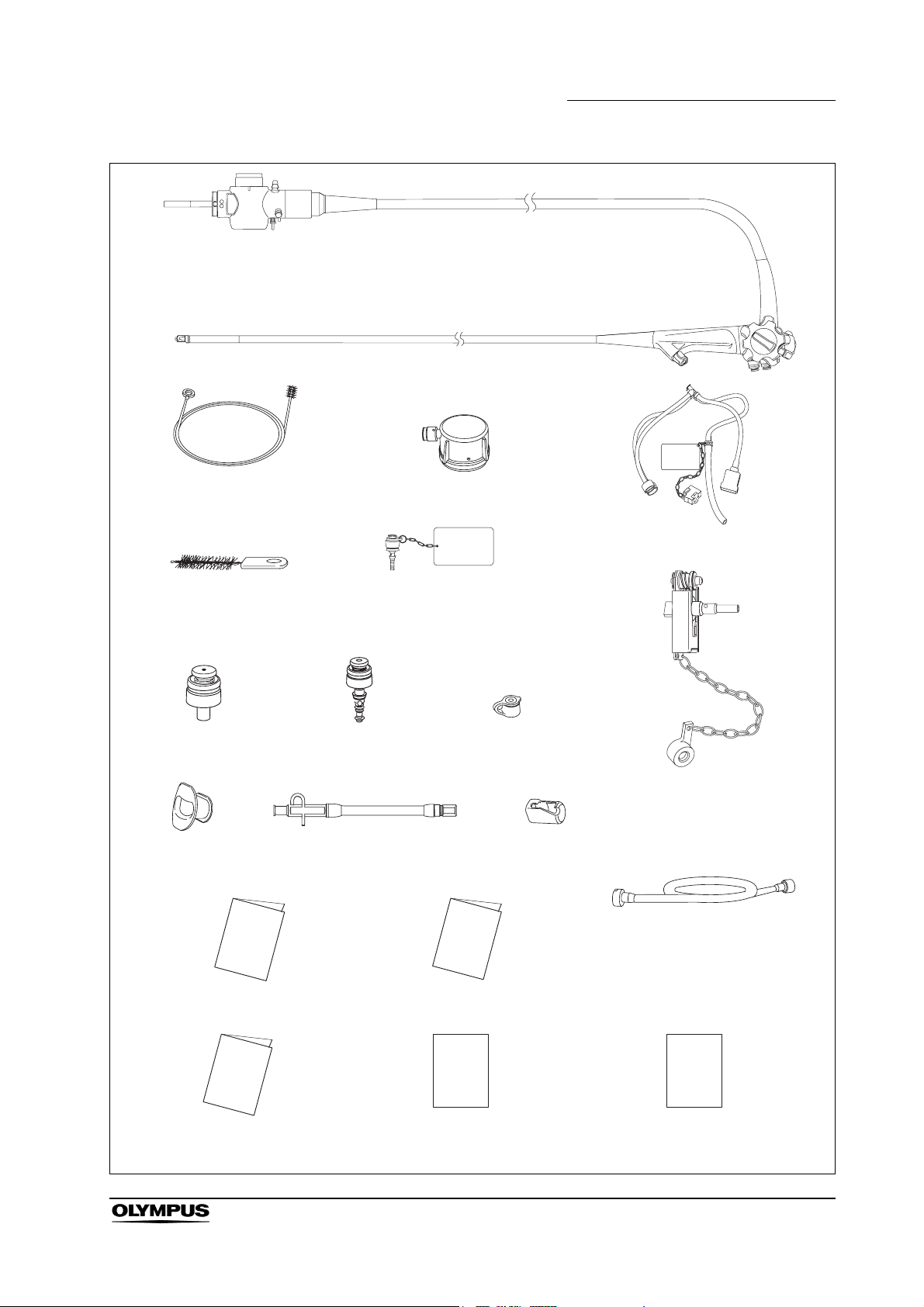
Endoscope
Chapter 1 Checking the Package Contents
Channel cleaning brush
(BW-20T)
Channel-opening cleaning
brush (MH-507)
Suction valve
(MH-443, 2 pcs)
Mouthpiece
(MB-142, 2 pcs)
Water-resistant cap (MH-553)
AW channel cleaning
adapter (MH-948)
Air/water valve
(MH-438, 2 pcs)
Washing tube
(MH-974)
Injection tube (MH-946)
Biopsy valve
(MB-358, 10 pcs)
Channel plug (MH-944)
Distal cover
(MAJ-311, 2 pcs)
Suction cleaning adapter
(MH-856)
Operation manual Reprocessing manual
Instruction manual
(Distal cover)
Instructions
(Caution for attaching
the distal cover)
EVIS EXERA TJF TYPE 160VR OPERATION MANUAL
Instructions
(Leaflet type,
fixing the guidewire)
9
Page 14
Chapter 2 Instrument Nomenclature and Specifications
Chapter 2 Instrument Nomenclature
and Specifications
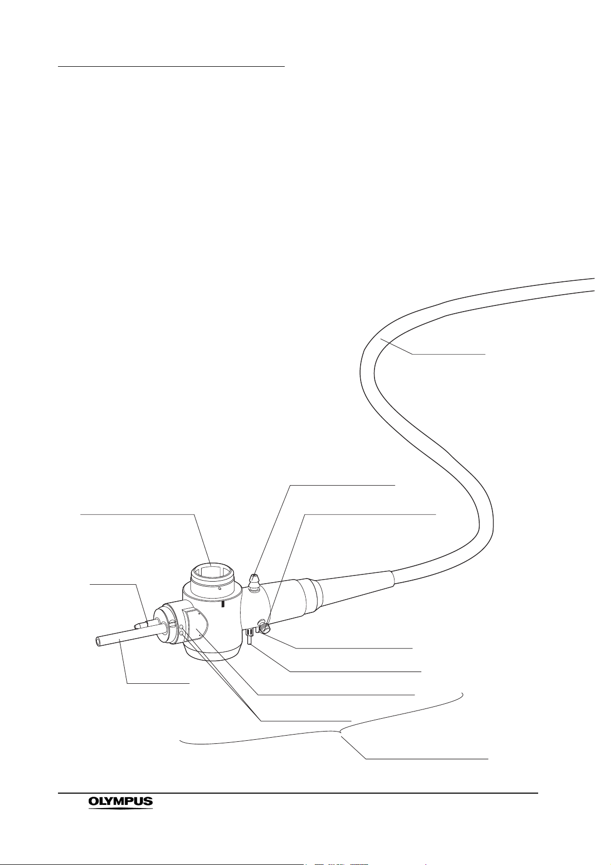
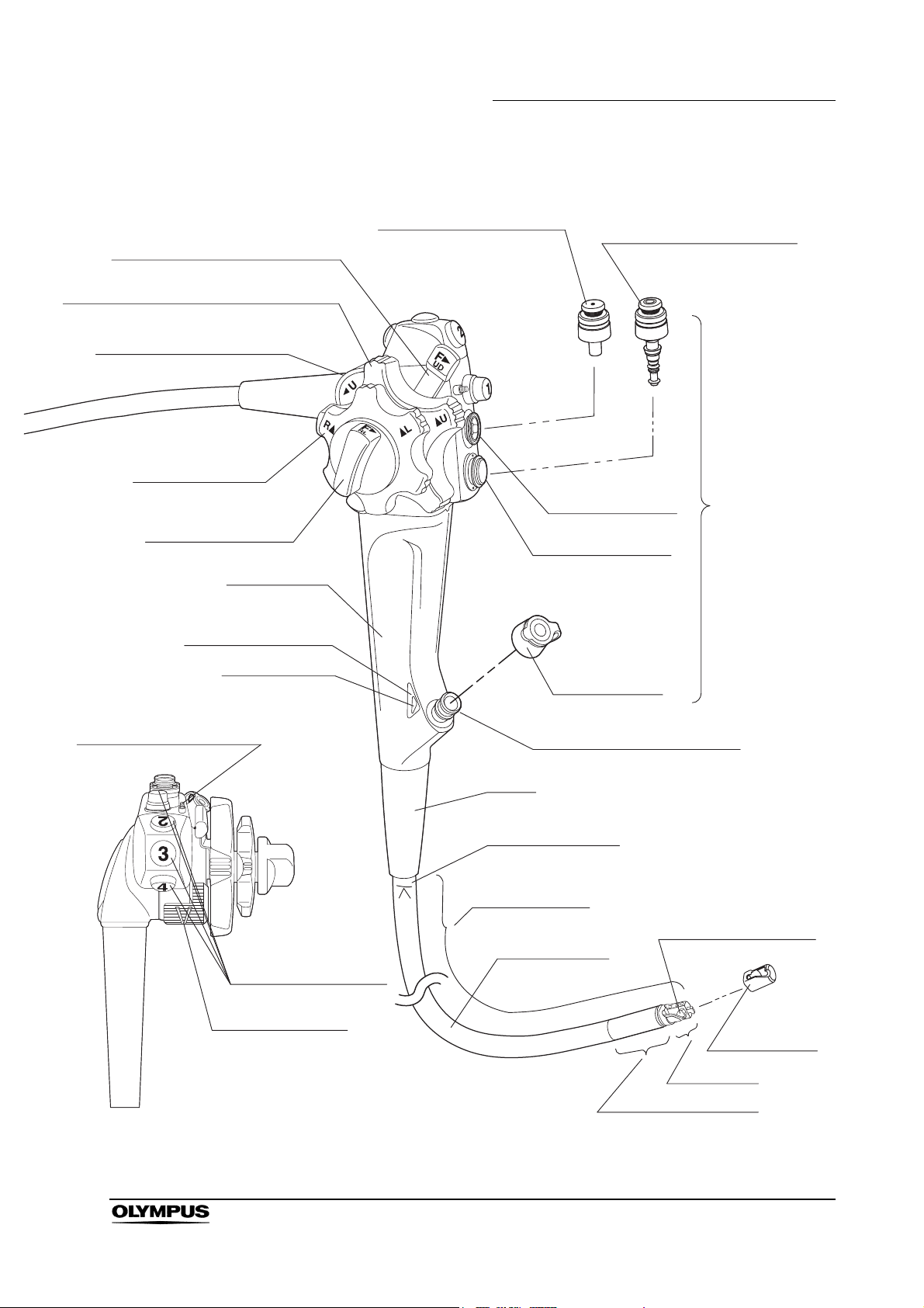
2.1 Nomenclature
Universal cord
Air pipe
1. Suction connector
2. S-cord connector mount5. Electrical connector
3. Air supply connector
3. Water supply connector
Light guide
Product name and serial number
Electrical contacts
4. Endoscope connector
10
EVIS EXERA TJF TYPE 160VR OPERATION MANUAL
Page 15
Chapter 2 Instrument Nomenclature and Specifications
7. UP/DOWN angulation lock
6. UP/DOWN angulation control knob
19. Elevator control lever
18. RIGHT/LEFT
angulation
control knob
17. RIGHT/LEFT
angulation lock
Grip section
Guidewire fixing
function color (blue)
16. Color code
8. Suction valve (MH-443)
Air/water cylinder
9. Air/water valve (MH-438)
Suction cylinder
Biopsy valve
(MB-358)
Control
section
15. Elevator channel plug
Guidewire fixing
function mark
To p v ie w
10. Instrument channel port
Boot
11. Insertion tube
limit mark
Working length
12. Forceps elevator
Insertion tube
14. Remote switches
Distal cover
(MAJ-311)
Distal end
13. Bending section
EVIS EXERA TJF TYPE 160VR OPERATION MANUAL
11
Page 16
Chapter 2 Instrument Nomenclature and Specifications
2.2 Endoscope functions
1. Suction connector
This connector connects the endoscope to the suction tube of the suction
pump.
2. S-cord connector mount
This mount connects the endoscope with the Olympus electrosurgical unit
via the S-cord. The S-cord conducts leakage current from the endoscope to
the electrosurgical unit. To connect the S-cord, refer to the instruction
manual for the electrosurgical unit.
3. Water supply connector and air supply connector
These connectors connect the endoscope to the water container via the
water container tube, to supply water to the distal end of the endoscope.
4. Endoscope connector
This connector connects the endoscope to the output socket of the light
source and transmits light from the light source to the endoscope.
5. Electrical connector
This connector connects the endoscope to the video system center via the
videoscope cable. The endoscope contains a memory chip that stores
information about the endoscope and communicates this information to the
video system center CV-160. For more details, refer to the instruction
manual of the CV-160.
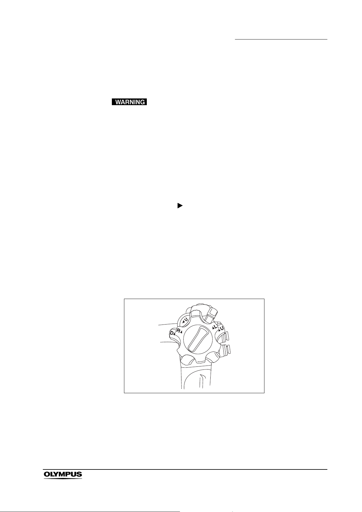
6. UP/DOWN angulation control knob
When this knob is turned in the “ U” direction, the bending section moves
UP; when the knob is turned in the “D ” direction, the bending section
moves DOWN.
7. UP/DOWN angulation lock
Moving this lock in the “F ” direction frees angulation. Moving the lock in
the opposite direction locks the bending section at any desired position.
8. Suction valve (MH-443)
This valve is depressed to activate suction. The valve is used to remove any
fluid, debris, flatus or air from the patient.
9. Air/water valve (MH-438)
The hole in this valve is covered to insufflate air and the valve is depressed
to feed water for lens washing. It also can be used to feed air to remove any
fluid or debris adhering to the objective lens.
12
10. Instrument channel port
The instrument channel port functions as:
− channel for the insertion of endo-therapy accessories
− suction channel
− fluid feed channel (from a syringe via the biopsy valve)
EVIS EXERA TJF TYPE 160VR OPERATION MANUAL
Page 17
Chapter 2 Instrument Nomenclature and Specifications
11. Insertion tube limit mark
This mark shows the maximum point to which the endoscope may be
inserted into the patient’s body.
12. Forceps elevator
The elevator moves endo-therapy accessories when the elevator control
lever is operated. In addition, the forceps elevator is used for assistance of
the fixation function of the guidewire while inserting/withdrawing the wire
guided type endo-therapy accessory.
13. Bending section
This section moves the distal end of the endoscope when the UP/DOWN
and RIGHT/LEFT angulation control knobs are operated.
14. Remote switches 1 to 4
The functions of remote switches 1 to 4 can be selected on the video system
center. When selecting the functions, also refer to the instruction manual for
the video system center.
15. Elevator channel plug
This plug is used for connection of the washing tube to clean and disinfect
the elevator channel.
16. Color code (orange)
This code is used to quickly determine the compatibility of endo-therapy
accessories. The endoscope can be used with endo-therapy accessories
that have the same color code.
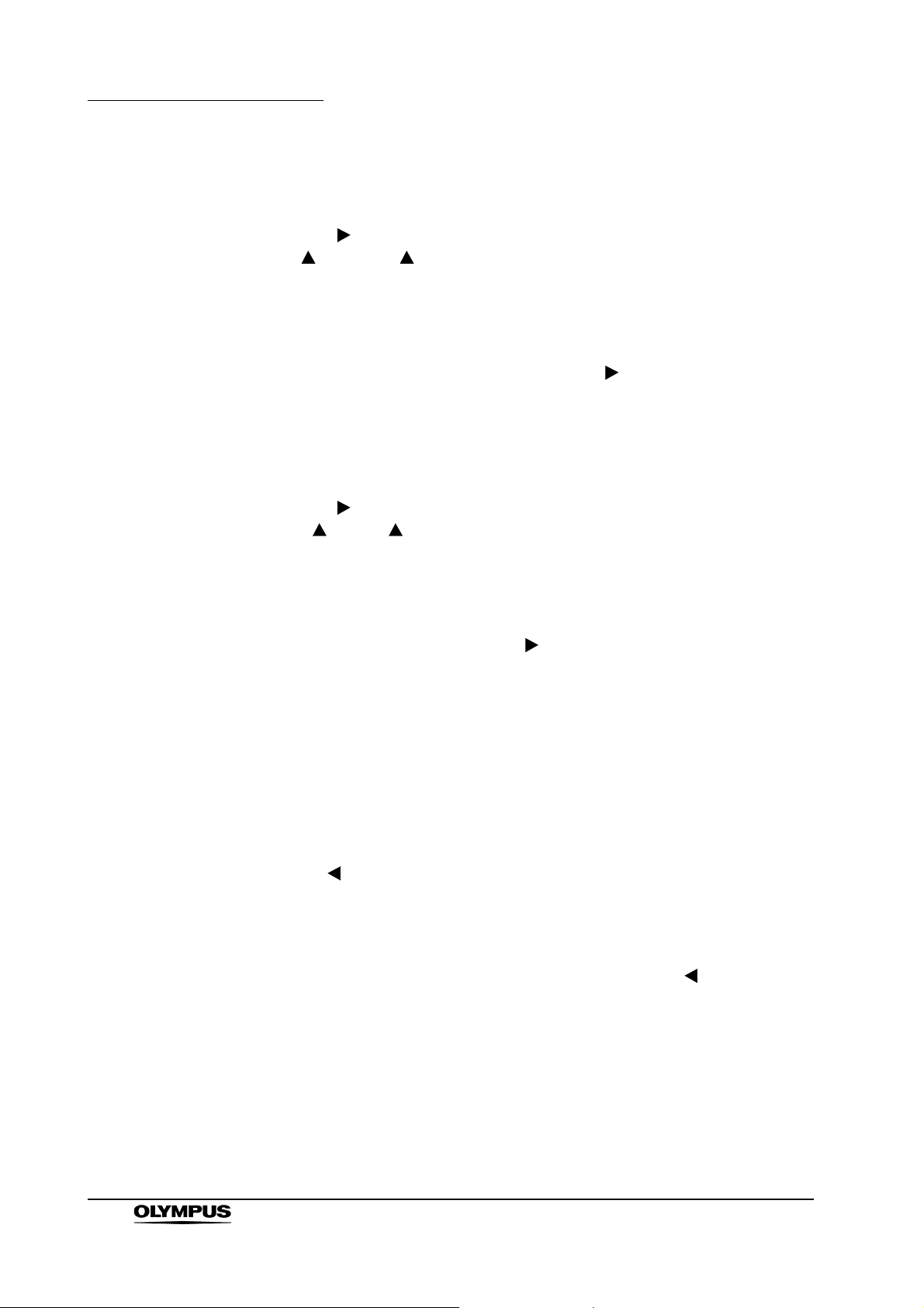
17. RIGHT/LEFT angulation lock
Turning this lock in the “F ” direction frees angulation. Turning the lock in
the opposite direction locks the bending section at any desired position.
18. RIGHT/LEFT angulation control knob
When this knob is turned in the “R ” direction, the bending section moves
RIGHT; when the knob is turned in the “ L” direction, the bending section
moves LEFT.
19. Elevator control lever
When this lever is moved in the “ U” direction, the forceps elevator is
raised. When the lever is turned in the opposite direction, the forceps
elevator is lowered.
EVIS EXERA TJF TYPE 160VR OPERATION MANUAL
13
Page 18

Chapter 2 Instrument Nomenclature and Specifications
2.3 Specifications
Environment
Operating
environment
Transportation and
storage
environment
Ambient temperature 10 – 40°C (50 – 104°F)
Relative humidity 30 – 85%
Atmospheric pressure 700 – 1060 hPa
(0.7 – 1.1 kgf/cm
(10.2 – 15.4 psia)
Ambient temperature –47 to 70°C (–52.6 to 158°F)
Relative humidity 10 – 95%
Atmospheric pressure 700 – 1060 hPa
(0.7 – 1.1 kgf/cm
(10.2 – 15.4 psia)
2
)
2
)
14
EVIS EXERA TJF TYPE 160VR OPERATION MANUAL
Page 19
Specifications
Endoscope functions
Model TJF-160VR
Optical system Field of view 100°
Insertion tube Distal end outer
Chapter 2 Instrument Nomenclature and Specifications
Direction of view Backward
Sideviewing 5°
Depth of field 5 – 60 mm
diameter
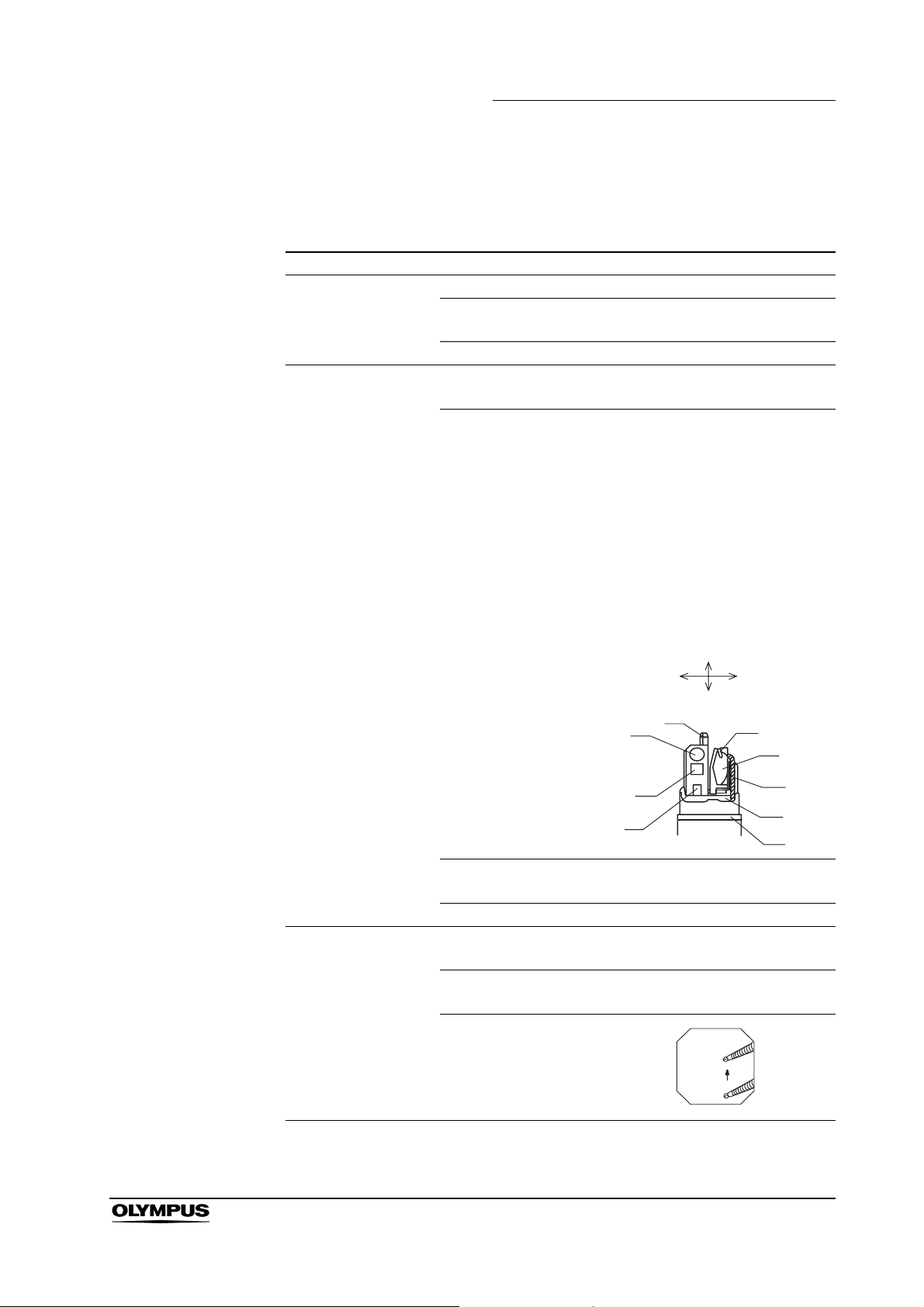
Distal end enlarged 1. Air/water nozzle
2. Objective lens
3. Light guide lens
4. Instrument channel outlet
5. Forceps elevator
6. Guidewire-locking groove
7. Elevator wire
8. Hook
9. White ring
ø13.5mm
Insertion tube outer
diameter
Working length 1240 mm
Instrument channel Channel inner
diameter
Minimum visible
distance
Direction from which
endo-therapy
accessories enter
and exit the
endoscopic image
LEFT
3.
1.
2.
UP
DOWN
8.
ø11.3mm
ø4.2mm
10 mm
RIGHT
6.
5.
7.
4.
9.
EVIS EXERA TJF TYPE 160VR OPERATION MANUAL
15
Page 20

Chapter 2 Instrument Nomenclature and Specifications
Air flow rate
Note: Standard when CLV-160 (high
air pressure) is used.
Bending section Angulation range UP 120°, DOWN 90°
RIGHT 110°, LEFT 90°
Total length 1550 mm
Medical Device
Directive
EMC Applied standard;
IEC 60601-1-2: 2001
This device complies with the
requirements of Directive 93/42/EEC
concerning medical devices.
Classification: Class ΙΙ a
This instrument complies with the
standards listed in the left column.
CISPR 11 of emission:
Group 1, Class B
This instrument complies with the
EMC standard for medical electrical
equipment; edition 2 (IEC 60601-1-2:
2001). However, when connecting to
an instrument that complies with the
EMC standard for medical electrical
equipment; edition 1 (IEC 60601-1-2:
1993), the whole system complies
with edition 1.
25 cm
3
/s
16
Year of manufacture
Degree of protection
against electric
shock
2412345
The last digit of the year of
manufacture is the second digit of the
serial number.
TYPE BF applied part
EVIS EXERA TJF TYPE 160VR OPERATION MANUAL
Page 21
Chapter 3 Preparation and Inspection
Chapter 3 Preparation and Inspection
Before each case, prepare and inspect this instrument as instructed below.
Inspect other equipment to be used with this instrument as instructed in their
respective instruction manuals. If the irregularities are suspected after
inspection, follow the instructions given in Chapter 5, “Troubleshooting”.
If this instrument malfunctions, do not use it. Return it to Olympus for repair as
described in Section 5.3, “Returning the endoscope for repair”.
• Using an endoscope that is not functioning properly may
compromise patient or operator safety and may result in
more severe equipment damage.
• This instrument was not cleaned, disinfected or sterilized
before shipment. Before using this instrument for the first
time, reprocess it according to the instructions given in the
endoscope’s companion manual, the “REPROCESSING
MANUAL” whose cover lists the model of your endoscope.
EVIS EXERA TJF TYPE 160VR OPERATION MANUAL
17
Page 22
Chapter 3 Preparation and Inspection
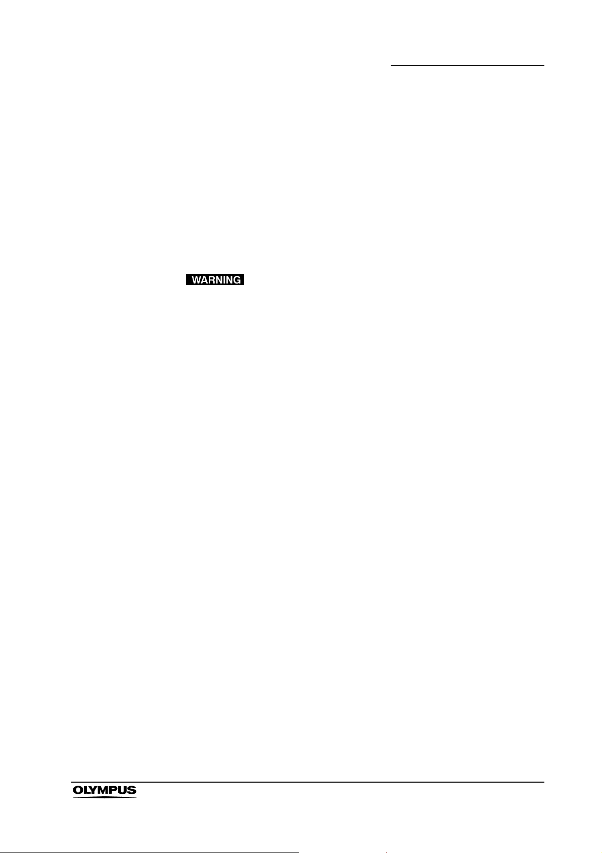
3.1 Preparation of the equipment
Prepare the equipment shown in Figure 3.1 (for compatibility, see the “System
chart” in the Appendix) and personal protective equipment, such as eye wear,
face mask, moisture-resistant clothing and chemical-resistant gloves, before
each use. Refer to the respective instruction manuals for each piece of
equipment.
Video monitor
Video system center
Light source
Water container
Suction pump
Endoscope
Endo-therapy accessories Mouthpiece Distal cover
• Paper towels • Trays • Lint-free cloths • Personal protective equipment
Figure 3.1
18
EVIS EXERA TJF TYPE 160VR OPERATION MANUAL
Page 23
3.2 Inspection of the endoscope
Clean and disinfect or sterilize the endoscope as described in the
“REPROCESSING MANUAL” whose cover lists the model of your endoscope.
Then remove the water-resistant cap from the endoscope connector.
Inspection of the endoscope
1. Inspect the control section and the endoscope connector for excessive
scratching, deformation, loose parts or other irregularities.
2. Inspect the boot and the insertion tube near the boot for bends, twists or
other irregularities.
3. Inspect the external surface of the entire insertion tube including the
bending section and the distal end for dents, bulges, swelling, scratching,
holes, sagging, transformation, bends, adhesion of foreign bodies, dropout
of parts, any protruding objects or other irregularities.
Chapter 3 Preparation and Inspection
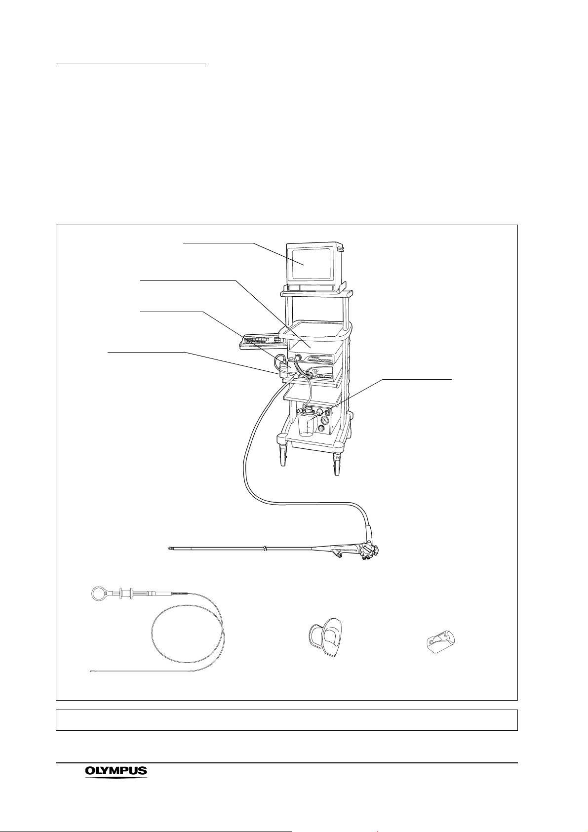
4. Holding the insertion tube gently with one hand, carefully run the fingertips
over the entire length of the insertion tube in both directions (see Figure
3.2). Confirm that no object or protrusion of metallic wire around the
insertion tube is stopping the hand. Also confirm that the insertion tube is
not abnormally rigid.
Figure 3.2
EVIS EXERA TJF TYPE 160VR OPERATION MANUAL
19
Page 24
Chapter 3 Preparation and Inspection
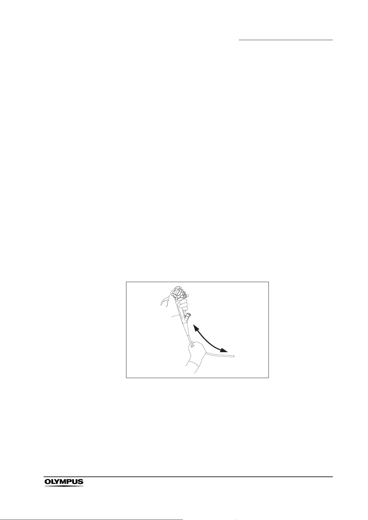
5. Using both hands, bend the insertion tube of the endoscope into a
semicircle. Then, moving your hands as shown by the arrows, confirm that
the entire insertion tube can be smoothly bent to form a semicircle and that
the insertion tube is sufficiently pliable (see Figure 3.3).
Figure 3.3
6. Gently hold the midpoint of the bending section and a point 20 cm from the
distal end. Push and pull gently to confirm that the junction between the
bending section and the insertion tube is not loose.
7. Inspect the objective lens and light guide lens at the distal end of the
endoscope’s insertion tube for scratching, cracks, stains, gaps around the
lens or other irregularities.
8. Inspect the air/water nozzle at the distal end of the endoscope’s insertion
tube for abnormal swelling, bulges, dents or other irregularities.
9. Inspect the guidewire locking groove of the forceps elevator for stain.
20
EVIS EXERA TJF TYPE 160VR OPERATION MANUAL
Page 25
Inspection of the bending mechanisms
Perform the following inspections while the bending section is straight.
If the movement of the UP/DOWN angulation lock,
RIGHT/LEFT angulation lock and their angulation control
knobs are loose and/or not smooth, or the bending section
does not angulate smoothly, the bending mechanism may be
abnormal. In this case, do not use the endoscope because it
may be impossible to straighten the bending section during
an examination.
Inspection for smooth operation
1. Confirm that both the UP/DOWN and RIGHT/LEFT angulation locks move
all the way in the “F ” direction.
Chapter 3 Preparation and Inspection
2. Turn the UP/DOWN and RIGHT/LEFT angulation control knobs slowly in
each direction until they stop, and return to their respective neutral
positions. Confirm that the bending section angulates smoothly and
correctly, and confirm that maximum angulation can be achieved and return
the bending section to its respective neutral positions.
3. When the UP/DOWN and RIGHT/LEFT angulation control knobs are turned
to their respective neutral positions as shown in Figure 3.4, confirm that the
bending section returns smoothly to an approximately straight condition.
Figure 3.4
EVIS EXERA TJF TYPE 160VR OPERATION MANUAL
21
Page 26
Chapter 3 Preparation and Inspection
Inspection of the UP/DOWN angulation mechanism
1. Move the UP/DOWN angulation lock all the way in the opposite direction of
the “F ” mark. Then turn the UP/DOWN angulation control knob in the
“ U” or the “D ” direction until it stops.
2. Confirm that the angle of the bending section is roughly stabilized when the
UP/DOWN angulation control knob is released.
3. Confirm that the bending section straightens out when the UP/DOWN
angulation lock is moved all the way in the “F ” direction and the
UP/DOWN angulation control knob is released.
Inspection of the RIGHT/LEFT angulation mechanism
1. Turn the RIGHT/LEFT angulation lock all the way in the opposite direction of
the “F ” mark. Then turn the RIGHT/LEFT angulation control knob in the
“R ” or the “ L” direction until it stops.
2. Confirm that the angle of the bending section is roughly stabilized when the
RIGHT/LEFT angulation control knob is released.
3. Confirm that the bending section straightens out when the RIGHT/LEFT
angulation lock is turned in the “F ” direction and the RIGHT/LEFT
angulation control knob is released.
Inspection of the forceps elevator mechanism
Perform the following inspections while the bending section is straight.
Inspection for smooth operation
1. Move the elevator control lever slowly all the way in the opposite direction of
the “ U” direction. Visually confirm that the portion of the elevator wire
extending from the distal end of the insertion tube is not broken or bent (see
Figure 3.5).
2. While observing the forceps elevator at the distal end of the insertion tube,
slowly move the elevator control lever all the way in the “ U” direction.
Confirm that the lever can be operated smoothly and that the forceps
elevator is raised smoothly. Also confirm that the forceps elevator remains
stationary when pushed from behind while holding the elevator control lever
stationary (see Figure 3.5).
22
EVIS EXERA TJF TYPE 160VR OPERATION MANUAL
Page 27

Chapter 3 Preparation and Inspection
3. Move the elevator control lever slowly all the way in the opposite direction of
the “ U” direction. Confirm that the lever can be operated smoothly and
that the forceps elevator is lowered smoothly (see Figure 3.5).
Elevator control
lever
Forceps elevator
Elevator wire
Figure 3.5
3.3 Preparation and inspection of accessories
Clean and disinfect or sterilize the air/water valve, suction valve, biopsy valve
and distal cover as described in the endoscope’s companion reprocessing
manual.
Inspection of the air/water and suction valves
Confirm that the top hole of the air/water valve is not blocked
(see Figure 3.6). If the hole is blocked, air is fed continuously
and patient pain, bleeding and/or perforation can result.
EVIS EXERA TJF TYPE 160VR OPERATION MANUAL
23
Page 28

Chapter 3 Preparation and Inspection
1. Confirm that the holes of the valves are not blocked (see Figures 3.6 and
3.7).
2. Confirm that the valves are not deformed or cracked (see Figures 3.6 and
3.7).
3. Check for excessive scratching or tears in the air/water valve’s seals (see
Figure 3.6).
Hole
Spring
Figure 3.6
Spring
Figure 3.7
Seals
Air/water valve (MH-438)
Suction valve (MH-443)
Skirt
Hole
Skirt
Hole
24
The air/water and suction valves are consumable items. If the
inspection of the air/water or suction valve reveals any
irregularities, use new valves.
EVIS EXERA TJF TYPE 160VR OPERATION MANUAL
Page 29

Inspection of the biopsy valve
The biopsy valve is a consumable item that should be
inspected before each use. Replace it with a new one if
irregularities are observed by following inspection. An
irregular, abnormal or damaged valve can reduce the efficacy
of the endoscope’s suction system, and may leak or spray
patient debris or fluids, posing an infection-control risk.
1. Confirm that the slit and hole on the biopsy valves have no splits, cracks,
deformation, discoloration or other damage (see Figure 3.8).
Normal Abnormal
Slit
Chapter 3 Preparation and Inspection
Discoloration
Cap
Hole
Main body
Figure 3.8
Discoloration
Splits, cracks
2. Attach the cap to the main body (see Figure 3.9).
Slit
Main bodyCap
Figure 3.9
EVIS EXERA TJF TYPE 160VR OPERATION MANUAL
25
Page 30

Chapter 3 Preparation and Inspection
Inspection of the distal cover
• The distal cover has not been sterilized prior to shipping.
Using a distal cover that has not been disinfected or sterilized
may result in patient infection.
• Should the slightest irregularity be suspected when
inspecting the distal cover, do not use it. A defective distal
cover could fall off during the examination. Continuing the
examination after the distal cover has fallen off may cause
patient injury by the exposed distal end of the endoscope.
• Only the distal cover (MAJ-311) can be used with
TJF-160VR. If the TJF-160VR is used in combination with a
wrong distal cover, it may fall off the distal end during the
examination. Continuing the examination after the distal
cover has fallen off may cause patient injury by the exposed
distal end of the endoscope.
1. Confirm that the metal insert of the distal cover is intact (see Figure 3.10).
Metal insert
Top end of the
distal cover
Bottom end of the
distal cover
Figure 3.10
Distal cover’s
opening
Distal cover’s
cap
Indication mark
2. Confirm that the distal cover’s cap has not peeled off of the metal insert.
3. Confirm that the distal cover is free from cracks, wrinkles, discoloration,
wear, pinholes or other irregularities.
26
EVIS EXERA TJF TYPE 160VR OPERATION MANUAL
Page 31

Inspection of the mouthpiece
Do not use a mouthpiece that is damaged, deformed or
reveals other irregularities. Doing so may cause patient injury
and/or equipment damage.
Placing the mouthpiece in the patient’s mouth before the
procedure prevents the patient from biting and/or damaging
the endoscope’s insertion tube.
1. Confirm that the mouthpiece is free from cracks, deformation or
discoloration (see Figure 3.11).
2. Using your fingers, check for excessive scratching or other irregularities on
all surfaces of the mouthpiece (see Figure 3.11).
Chapter 3 Preparation and Inspection
Opening
Main body
Figure 3.11
Outer flange
EVIS EXERA TJF TYPE 160VR OPERATION MANUAL
27
Page 32

Chapter 3 Preparation and Inspection
3.4 Attaching accessories to the endoscope
The air/water valve and the suction valve do not require
lubrication. Lubricants can cause swelling of the valves’
seals, which will impair valve function.
Attaching the suction valve
1. Align the two metal ridges on the underside of the suction valve with the two
holes in the suction cylinder.
2. Attach the suction valve to the suction cylinder of the endoscope (see
Figures 3.12 and 3.13). Confirm that the valve fits properly without any
bulging of the skirt. Also confirm that the valve cannot be rotated.
Two metal ridges
Figure 3.12
Skirt
Side view
Top viewBottom view
The suction valve will make a whistling noise when it is dry;
this does not indicate a malfunction.
Suction cylinder
Suction cylinder
Two holes
28
EVIS EXERA TJF TYPE 160VR OPERATION MANUAL
Page 33

Attaching the air/water valve
1. Attach the air/water valve to the air/water cylinder of the endoscope (see
Figure 3.13).
2. Confirm that the valve fits properly without any bulging of the skirt.
Air/water valve
Suction valve
Skirt
Suction cylinder
Air/water cylinder
Chapter 3 Preparation and Inspection
Figure 3.13
The air/water valve may stick at first, but it should operate
smoothly after it is depressed a few times.
EVIS EXERA TJF TYPE 160VR OPERATION MANUAL
29
Page 34

Chapter 3 Preparation and Inspection
Attaching the biopsy valve
Attach the biopsy valve to the instrument channel port of the endoscope (see
Figure 3.14). Confirm that the biopsy valve fits properly.
If a biopsy valve is not properly connected to the instrument
channel port, it can reduce the efficacy of the endoscope’s
suction system and may cause patient debris to leak or spray
from the endoscope.
Biopsy valve
Instrument
channel port
Figure 3.14
30
EVIS EXERA TJF TYPE 160VR OPERATION MANUAL
Page 35

Attaching the distal cover
• Never use the endoscope unless the distal cover is properly
attached to the distal end. If the distal cover is not attached
correctly, it may slip off or fall off the distal end during the
examination. This could result in thermal injury when the
endoscope is used with high-frequency endo-therapy
accessories. And, continuing the examination after the distal
cover has fallen off may cause patient injury by the exposed
distal end of the endoscope.
• If a distal cover with cracks or pinholes is used, it could fall off
during the examination and/or, it may cause thermal injury
because an electric current leaks from cracks or pinholes
when high-frequency cauterization treatment is performed.
Never use a distal cover with cracks or pinholes but replace it
with a new one.
Chapter 3 Preparation and Inspection
• Do not put silicone oil, olive oil, or products containing
petroleum-based lubricants (e.g.Vaseline) on the distal cover
or the distal end. Silicone oil may cause deterioration of the
distal cover. If the distal cover is damaged this way, it may
slip off or fall off during the examination. Continuing the
examination after the distal cover has fallen off may cause
patient injury by the exposed distal end of the endoscope. It
could also result in thermal injury when used in combination
with high-frequency endo-therapy accessories.
When attaching the distal cover, gently hold the bending
section as close to the distal end as possible. Forcefully
grasping other parts of the bending section can damage the
mechanism of the bending section or deform its covering.
EVIS EXERA TJF TYPE 160VR OPERATION MANUAL
31
Page 36

Chapter 3 Preparation and Inspection
1. Keep the bending section straight and move the elevator control lever to set
the forceps elevator beside the side wall area of the distal end as shown in
Figure 3.15.
White ring
Bending section
Figure 3.15
Forceps elevator
Distal end
Side wall area
Hook
2. Gently hold the covering of the bending section as close to the distal end as
possible (see Figure 3.16). Hold the top end of the distal cover with the
metal insert (see Figure 3.16). Align the indication mark on the white ring
with the indication mark on the distal cover.
Indication mark
Indication mark
32
White ring
Figure 3.16
EVIS EXERA TJF TYPE 160VR OPERATION MANUAL
Page 37

Chapter 3 Preparation and Inspection
3. Push the distal cover straight onto the distal end of the endoscope until the
bottom end of the distal cover contacts the end part of the white ring. Hold
the bending section lightly close to the distal end and press the distal cover
about 1 mm onto the distal end. When pressing the distal cover, it extends
as shown in Figure 3.17.
When pressing the distal cover, it extends.
Figure 3.17
4. While maintaining the condition obtained in Step 3. (pressing the distal
cover), turn the top end of the distal cover clockwise until it stops as shown
in Figure 3.18.
5. After turning the distal cover, pull it lightly towards the top end of the distal
cover to attach it properly to the distal end. Pulling holds the distal cover on
the distal end of the endoscope completely. If the distal cover cannot be
turned, it may not be pressed enough. Refer to Step 3. as shown above and
repeat the Step from 3. to 5.
3. Pull
2. Turn
1. Push
Figure 3.18
EVIS EXERA TJF TYPE 160VR OPERATION MANUAL
33
Page 38

Chapter 3 Preparation and Inspection
6. Confirm that there are no gaps between the distal end of the endoscope and
the distal cover at the two positions indicated by the arrows in Figure 3.19.
Figure 3.19
7. Confirm that the part of the distal cover indicated by an arrow and the optic
surface of the endoscope are aligned as shown in Figure 3.20.
White ring
Optic surface
of endoscope
Figure 3.20
34
EVIS EXERA TJF TYPE 160VR OPERATION MANUAL
Page 39

Chapter 3 Preparation and Inspection
8. Hold the bottom end of the distal cover and turn it to adjust the indication
mark to the straight position as shown in Figure 3.21.
Indication mark
Figure 3.21
9. Confirm that the bottom end of the distal cover does not spread as shown by
the arrows in Figure 3.22, and that the white ring of the distal end is not
covered by the distal cover as shown in Figure 3.22. Stroke the distal cover
with your fingers and pay attention that the distal cover is not put over the
distal end as shown in Figure 3.23. Otherwise, the distal cover may be
damaged. When Continuing the examination with the condition like
mentioning above is confirmed, the distal cover may slip off the distal end
during the examination. Replace the distal cover with a new one.
Normal Abnormal
White ring
Figure 3.22
EVIS EXERA TJF TYPE 160VR OPERATION MANUAL
35
Page 40

Chapter 3 Preparation and Inspection
Figure 3.23
10. Pull the distal cover gently and confirm that the distal cover and the distal
end of the endoscope do not separate (see Figure 3.24).
11. Twist the distal cover gently in both directions and confirm that the distal
cover and the distal end of endoscope do not separate (see Figure 3.24).
Exchange the distal cover when it is rolled up.
Pull
Twi st
Figure 3.24
12. Confirm that the distal cover is free of cracks, wrinkles or pinholes.
13. While observing the forceps elevator at the distal end of the endoscope,
move the elevator control lever slowly several times all the way in both the
“ U” direction and to the right. Confirm that the forceps elevator is not
blocked by the distal cover.
14. Confirm that the distal cover cannot be seen on the endoscopic image. Even
if the distal cover can been seen partly on the endoscopic image, it is not
attached properly to the distal end. Detach the distal cover from the distal
end. Refer to Step 1. as shown above and repeat the Step from 1. to 14.
36
EVIS EXERA TJF TYPE 160VR OPERATION MANUAL
Page 41

Chapter 3 Preparation and Inspection
3.5 Inspection and connection of ancillary equipment
Inspection of ancillary equipment
• Attach the water container to the specified receptacle on the
trolley or the light source. If the water container is attached
anywhere else, water may drip from the water container’s
water supply tube, and equipment malfunction can result.
• Take care not to spill water from the water container’s
connection adapter when detaching the connection adapter
from the endoscope. Spilled water could splash on the
equipment, and it may cause equipment malfunction.
Prepare and inspect the light source, video system center, video monitor, water
container, suction pump and endo-therapy accessories as described in their
respective instruction manuals.
Connection of the endoscope and ancillary equipment
Firmly connect the suction tube from the suction pump to the
suction connector on the endoscope connector. If the suction
tube is not attached properly, debris may drip from the tube
and can present an infection-control risk, damage and/or
reduce the performance.
EVIS EXERA TJF TYPE 160VR OPERATION MANUAL
37
Page 42

Chapter 3 Preparation and Inspection
1. If any ancillary equipment is ON, turn it OFF.
2. Insert the endoscope connector completely into the scope socket (output
socket when using the CLV-U20/U40) of the light source.
3. Connect the water container’s connection adapter to the air supply
connector and water supply connector (see Figure 3.25).
4. Confirm that the water container’s connection adapter fits properly and that
the water container’s connection adapter cannot be rotated.
(1) (2) (3) (4)
Water container’s connection adapter
Endoscope connector
Figure 3.25
5. Align the mark on the videoscope cable EXERA or the videoscope cable
100 with mark 1 on the endoscope connector and push it in until it stops
(see Figure 3.26).
Air supply connector
Water supply connector
Mark 2 (yellow)
Mark (yellow)
38
Mark 1 (yellow)
Figure 3.26
EVIS EXERA TJF TYPE 160VR OPERATION MANUAL
Page 43

Chapter 3 Preparation and Inspection
6. Turn the connector of the videoscope cable clockwise until it stops (see
Figure 3.26).
7. Confirm that the mark on the videoscope cable is aligned with mark 2 on the
endoscope connector.
8. Connect the suction tube from the suction pump to the suction connector on
the endoscope connector (see Figure 3.27).
Suction pump
Suction tube
Figure 3.27
3.6 Inspection of the endoscopic system
Inspection of the endoscopic image
Do not stare directly at the distal end of the endoscope while
the examination light is ON. Otherwise, eye injury may result.
1. Turn ON the video system center, light source and video monitor and
inspect the endoscopic image as described in their respective instruction
manuals.
2. Confirm the examination light output.
3. While observing the palm of your hand, confirm that the endoscopic image
is free from noise, blur, fog or other irregularities.
4. Angulate the endoscope and confirm that the endoscopic image is free from
momentary disappearing or other irregularities.
5. If the distal cover is visible on the endoscopic image, reattach the distal
cover correctly to the distal end.
EVIS EXERA TJF TYPE 160VR OPERATION MANUAL
39
Page 44

Chapter 3 Preparation and Inspection
Inspection of remote switch
Depress every remote control switch and confirm that the specified functions
work normally.
If the object cannot be seen clearly, wipe the objective lens
using a clean, lint-free cloth moistened with 70% ethyl or
isopropyl alcohol.
All remote control switches should be checked to work
normally even when they are not expected for use. The
endoscopic image may freeze or other irregularities may
occur during examination and may cause patient injury,
bleeding and/or perforation.
Inspection of the air feeding function
1. Set the airflow regulator on the light source to “High”, as described in the
light source’s instruction manual.
2. Immerse the distal end of the insertion tube in sterile water to a depth of
10 cm and confirm that no air bubbles are emitted when the air/water valve
is not operated.
3. Cover the hole in the air/water valve with your finger and confirm that air
bubbles are continuously emitted from the air/water nozzle.
4. Uncover the hole in the air/water valve and confirm that no air bubbles are
emitted from the air/water nozzle.
If a stream of air bubbles is emitted from the air/water nozzle
even though the air/water valve is not being operated and the
distal end of the insertion tube is 10 cm or more below the
surface of the sterile water, an irregularity in the air feeding
function may be suspected. If the endoscope is used while
air is continuously being fed, over-insufflation and patient
injury may result.
If air bubbles are emitted from the air/water nozzle, remove
and reattach the air/water valve correctly, or replace it with a
new one. If this fails to stop air bubbles from being emitted,
do not use the endoscope, as there may be a malfunction.
Contact Olympus.
40
EVIS EXERA TJF TYPE 160VR OPERATION MANUAL
Page 45

Chapter 3 Preparation and Inspection
When the distal end of the insertion tube is immersed less
than 10 cm below the surface of the sterile water, a small
amount of air bubbles may be emitted from the air/water
nozzle even when the air/water valve is not operated. This
does not indicate a malfunction.
Inspection of the objective lens cleaning function
Use sterile water only. Non-sterile water may cause patient
cross-contamination and infection.
• When the air/water valve is depressed for the first time, it
may take a few seconds before water is emitted.
• If the air/water valve returns to its original position slowly after
water feeding, remove the air/water valve and moisten the
seals with sterile water.
• During the inspection, place the distal end of the endoscope
in a beaker or other container so that the floor does not get
wet.
1. Keep the air/water valve’s hole covered with your finger and depress the
valve. Observe the endoscopic image and confirm that water flows on the
entire objective lens.
2. Release the air/water valve. Observe the endoscopic image and confirm
that the emission of water stops and that the valve returns smoothly to its
original position.
3. While observing the endoscopic image, feed air after feeding water by
covering the hole in the air/water valve with your finger. Confirm that the
emitted air removes the remaining water on the objective lens and clears the
endoscopic image.
EVIS EXERA TJF TYPE 160VR OPERATION MANUAL
41
Page 46

Chapter 3 Preparation and Inspection
Inspection of the suction function
1. Place the container of sterile water and the endoscope on the same height.
For the inspection, adjust the suction pressure to the same level as it will be
during the procedure.
• If the suction valve does not operate smoothly, detach it and
reattach it, or replace it with a new one. If the endoscope is
used while the suction valve is not working properly, it may
be impossible to stop suction, which could cause patient
injury. If the reattached or replaced suction valve fails to
operate smoothly, the endoscope may be malfunctioning;
stop using it and contact Olympus.
• If the biopsy valve leaks, replace it with a new one. A leaking
biopsy valve can reduce the efficacy of the endoscope’s
suction system, and may leak or spray patient debris or
fluids, posing an infection-control risk.
2. Immerse the distal end of the insertion tube in sterile water with the
endoscope’s instrument channel port at the same height as the water level
in the water container. Press the suction valve and confirm that water is
continuously aspirated into the suction bottle of the suction pump.
3. Release the suction valve. Confirm that suction stops and the valve returns
to its original position.
4. Depress the suction valve and aspirate water for one second. Then, release
the suction valve for one second. Repeat this several times and confirm that
no water leaks from the biopsy valve.
5. Remove the distal end of the endoscope from the water. Depress the
suction valve and aspirate air for a few seconds to remove any water from
the instrument channel.
42
EVIS EXERA TJF TYPE 160VR OPERATION MANUAL
Page 47

Chapter 3 Preparation and Inspection
Inspection of the instrument channel and forceps elevator
Keep your eyes away from the distal end when inserting
endo-therapy accessories. Extending the endo-therapy
accessory from the distal end could cause eye injury.
1. Confirm that the forceps elevator is lowered, then insert the endo-therapy
accessory through the biopsy valve. Confirm that the endo-therapy
accessory extends smoothly from the distal end, and that a foreign object
does not come out.
2. Extend the endo-therapy accessory approximately 3 cm from the distal end.
Move the elevator control lever in the “ U” direction and confirm that the
forceps elevator is raised smoothly.
3. Move the elevator control lever in the opposite direction of the “ U”
direction and confirm that the forceps elevator is lowered.
4. Confirm that the endo-therapy accessory can be withdrawn smoothly from
the biopsy valve.
EVIS EXERA TJF TYPE 160VR OPERATION MANUAL
43
Page 48

Chapter 4 Operation
Chapter 4 Operation
The operator of this instrument must be a physician or medical personnel under
the supervision of a physician and must have received sufficient training in
clinical endoscopic technique. This manual, therefore, does not explain or
discuss clinical endoscopic procedures. It only describes basic operation and
precautions related to the operation of this instrument.
• Wear personal protective equipment to guard against
dangerous chemicals and potentially infectious material
during operation. During operation, wear appropriate
personal protective equipment, such as eye wear, face mask,
moisture-resistant clothing and chemical-resistant gloves that
fit properly and are long enough so that your skin is not
exposed.
• The temperature of the distal end of the endoscope may
exceed 41°C (106°F) and reach 50°C (122°F) due to intense
endoscopic illumination. Surface temperatures over 41°C
(106°F) may cause mucosal burns. Always use the minimum
level of illumination, minimum time and suitable distance
necessary for adequate viewing. Whenever possible, avoid
close stationary viewing and do not leave the distal end of the
endoscope close to the mucous membrane for a long time.
• Whenever possible, do not leave the endoscope illuminated
before and/or after an examination. Continued illumination
will cause the distal end of the endoscope to become hot and
could cause operator and/or patient burns.
• Turn the video system center ON to operate the light source’s
automatic brightness function. When the video system center
is OFF, it cannot operate the light source’s automatic
brightness function, and the light intensity is set to the
maximum level. In this case, the distal end of the endoscope
can become hot and could cause operator and/or patient
burns.
44
EVIS EXERA TJF TYPE 160VR OPERATION MANUAL
Page 49

Chapter 4 Operation
• Never insert or withdraw the endoscope under any of the
following conditions. Otherwise, patient injury, bleeding
and/or perforation can result.
− Insertion or withdrawal while the endo-therapy accessory
extends from the distal end of the endoscope.
− Insertion or withdrawal while the bending section is locked
in position.
− Insertion or withdrawal with excessive force.
− Insertion or withdrawal while the forceps elevator is
raised.
• If any of the following phenomena occur during an
examination, immediately stop the examination and withdraw
the endoscope from the patient as described in Section 5.2,
“Withdrawal of the endoscope with an abnormality”.
− If any abnormality is suspected with the functionality of
the endoscope.
− If the endoscopic image on the video monitor disappears
or freezes unexpectedly.
− If the angulation control knob is locked.
− If the angulation control mechanism is not functioning
properly.
Continued use of the endoscope under these conditions
could result in patient injury, bleeding and/or perforation.
• If an abnormal endoscopic image/function occurs and returns
to its normal condition by itself, the endoscope may have
malfunctioned. Continuous use of such an endoscope may
cause repetition of the abnormality, and it may not return to
its normal condition. In this case, stop the examination
immediately and slowly withdraw the endoscope while
viewing the endoscopic image. Otherwise, patient injury,
bleeding and/or perforation can result.
• If the forceps elevator cannot be lowered while using an
endo-therapy accessory, stop the procedure immediately and
contact Olympus on keeping the condition.
• If the distal cover should fall off the distal end during the
examination, or seems to fall off, immediately stop the
examination, and slowly withdraw the endoscope from the
patient. Continuing the examination after the distal cover has
fallen off or seems to fall off may cause patient injury by the
exposed distal end of the endoscope.
EVIS EXERA TJF TYPE 160VR OPERATION MANUAL
45
Page 50

Chapter 4 Operation
4.1 Insertion
Set the brightness of the light source to the minimum
necessary to perform the procedure safely. If the endoscope
is used for a prolonged period at or near maximum light
intensity, vapor like smoke may be observed in the
endoscopic image. This is caused by the evaporation of
organic material (remaining blood, moisture of stool and so
on) due to heat generated by the light guide near the light
guide lens. If this vapor continues to interfere with the
examination, remove the endoscope, wipe the distal end of
the endoscope with a lint-free cloth moistened with 70% ethyl
or isopropyl alcohol, reinsert the endoscope and continue the
examination.
Holding and manipulating the endoscope
The control section of the endoscope is designed to be held in the left hand.
The air/water and suction valves can be operated using the left index finger. The
UP/DOWN angulation control knob and the elevator control lever can be
operated using the left thumb. The right hand is free to manipulate the insertion
tube and the RIGHT/LEFT angulation control knob (see Figure 4.1).
Figure 4.1
46
EVIS EXERA TJF TYPE 160VR OPERATION MANUAL
Page 51

Insertion of the endoscope
• Keep the elevator control lever moved all the way in the
opposite direction of the “ U” direction while inserting or
withdrawing the endoscope into or from the patient. If the
elevator control lever is moved all the way in the “ U”
direction and the forceps elevator is raised while inserting or
withdrawing the endoscope into or from the patient, this may
cause patient injury.
• Do not put silicone oil on the distal cover. Silicone oil may
cause deterioration of the distal cover. A deteriorated distal
cover may not be attached correctly and it may slip off or fall
off the distal end during the examination. Continuing the
examination after the distal cover has fallen off may cause
patient injury. It could also result in thermal injury when used
in combination with high-frequency endo-therapy
accessories.
Chapter 4 Operation
• To prevent the patient from accidentally biting the insertion
tube during an examination, it is strongly recommended that
a mouthpiece be placed in the patient’s mouth before
inserting the endoscope.
• Do not apply olive oil or products containing petroleum-based
lubricants (e.g. vaseline). These products may cause
stretching and deterioration of the bending section’s
covering.
• Do not allow the insertion tube to be bent within a distance of
10 cm or less from the junction of the boot. Insertion tube
damage can occur (see Figure 4.2).
> 10 cm
Figure 4.2
EVIS EXERA TJF TYPE 160VR OPERATION MANUAL
47
Page 52

Chapter 4 Operation
Angulation of the distal end
1. Move the elevator control lever in the opposite direction of the “ U”
direction until it stops.
2. If necessary, apply a medical-grade, water-soluble lubricant to the insertion
tube.
3. Place the mouthpiece between the patient’s teeth or gums, with the outer
flange on the outside of the patient’s mouth.
4. Insert the distal end of the endoscope through the opening of the
mouthpiece, then from the mouth to the pharynx, while viewing the
endoscopic image. Do not insert the insertion tube into the mouth beyond
the insertion tube limit mark.
Avoid forcible or excessive angulation, as this imposes load
on the wire controlling the bending section. This may cause
stretching or tearing of the wire and may impair the action of
the bending section.
1. Operate the angulation control knobs as necessary to guide the distal end
for insertion and observation.
2. The endoscope’s angulation locks are used to hold the angulated distal end
in position.
• When passing an endo-therapy accessory through the
instrument channel while the angulation is locked, the angle
of the distal end may change. When it is necessary to keep
the angulation stationary, hold the angulation control knobs in
place with your hand.
• When operating the UP/DOWN or RIGHT/LEFT angulation
lock, hold the angulation control knob stationary with your
finger. If this is not done, the angulation will change.
48
EVIS EXERA TJF TYPE 160VR OPERATION MANUAL
Page 53

Air/water feeding and suction
• Before using a syringe to inject liquid through the biopsy
valve, detach the valve’s cap from the main body. Then insert
the syringe straight into the valve and inject the liquid. If the
cap is not detached and/or the syringe is not inserted
straight, the biopsy valve could be damaged, which could
reduce the efficacy of the endoscope’s suction system, and
may leak or spray patient debris or fluids, posing an
infection-control risk.
• If the biopsy valve is left uncapped during the procedure,
debris or fluids could leak or spray from it, posing an
infection-control risk. When the valve is uncapped, place a
piece of sterile gauze over it to prevent leakage.
Air/water feeding
Chapter 4 Operation
• If the sterile water level in the water container is too low, then
air, not water, will be supplied. In this case, turn OFF the
airflow regulator on the light source and add sterile water till
the upper bound of the specified water level in the water
container.
• If air/water feeding does not stop, turn OFF the airflow
regulator on the light source and attach a new air/water
valve.
EVIS EXERA TJF TYPE 160VR OPERATION MANUAL
49
Page 54

Chapter 4 Operation
1. Cover the air/water valve’s hole to feed air from the air/water nozzle at the
distal end (see Figure 4.3).
2. Depress the air/water valve to feed water onto the objective lens (see Figure
4.3).
Suction valve
Air/water valve
Figure 4.3
50
EVIS EXERA TJF TYPE 160VR OPERATION MANUAL
Page 55

Suction
Chapter 4 Operation
• Avoid aspirating solid matter or thick fluids; channel or valve
clogging can occur. If the suction valve clogs and suction
cannot be stopped, disconnect the suction tube from the
suction connector on the endoscope connector. Turn the
suction pump OFF, detach the suction valve and remove
solid matter or thick fluids.
• When aspirating, maintain the suction pressure at the lowest
level necessary to perform the procedure. Excessive suction
pressure could cause aspiration of and/or injury to the
mucous membrane. In addition, patient fluids could leak or
spray from the biopsy valve, posing an infection-control risk.
• When aspirating, attach the cap to the main body of the
biopsy valve. The uncapped biopsy valve can reduce the
efficacy of the endoscope’s suction system, and may leak or
spray patient debris or fluids, posing an infection-control risk.
During the procedure, take notice that the suction bottle does
not fill completely. Aspirating fluids into a full bottle may
cause the suction pump to malfunction.
Depress the suction valve to aspirate excess fluid or other debris obscuring the
endoscopic image (see Figure 4.3).
Performing both air feeding and suction at the same time
sometimes makes it easier to remove water droplets from the
objective lens surface.
Observation of the endoscopic image
Refer to the light source’s instruction manual for instructions on how to adjust the
brightness.
EVIS EXERA TJF TYPE 160VR OPERATION MANUAL
51
Page 56

Chapter 4 Operation
4.2 Using endo-therapy accessories
For more information on combining the endoscope with particular endo-therapy
accessories, refer to the “System chart” in the Appendix and the instruction
manuals of the accessories. Refer to the accessories’ instruction manuals for
operating instructions.
• When using endo-therapy accessories, keep the distance
between the distal end of the endoscope and the mucous
membrane greater than the endoscope’s minimum visible
distance so that the endo-therapy accessory remains visible
in the endoscopic image. If the distal end of the endoscope is
placed closer than its own minimum visible distance, the
position of the accessory cannot be seen in the endoscopic
image, which could cause serious injury and/or equipment
damage. The minimum visible distance depends on the type
of endoscope being used. Refer to Section 2.3,
“Specifications”.
• When inserting or withdrawing an endo-therapy accessory,
confirm that its distal end is closed or completely retracted
into the sheath. Slowly insert or withdraw the endo-therapy
accessory straight into/from the slit of the biopsy valve.
Otherwise, the biopsy valve may be damaged and pieces of it
could fall off.
• If the insertion or withdrawal of endo-therapy accessories is
difficult, straighten the bending section as much as possible
without losing the endoscopic image. Inserting or
withdrawing endo-therapy accessories with excessive force
may damage the instrument channel or endo-therapy
accessories cause some parts to fall off and/or cause patient
injury.
• If the distal end of an endo-therapy accessory is not visible in
the endoscopic image, do not open the distal end or extend
the needle of the instrument. This could cause patient injury,
bleeding, perforation and/or equipment damage.
• Do not insert endo-therapy accessories without the forceps
elevator being raised. If they are inserted without the forceps
elevator being raised, the accessory cannot be observed in
the endoscopic image and it may cause patient injury.
52
EVIS EXERA TJF TYPE 160VR OPERATION MANUAL
Page 57

Chapter 4 Operation
• Do not insert or withdraw an endo-therapy accessory by
force when the forceps elevator is raised to its maximum
height. The instrument channel and/or the endo-therapy
accessory may be damaged and patient injury, bleeding
and/or perforation can result. If the endo-therapy accessory
cannot be inserted or withdrawn, move the elevator control
lever in the opposite direction of “ U” to lower the forceps
elevator and insert or withdraw the endo-therapy accessory.
• When using a biopsy forceps with a needle, confirm that the
needle is not bent excessively. A bent needle could protrude
from the closed cups of the biopsy forceps. Using such a
biopsy forceps could damage the instrument channel and/or
cause patient injury.
• When using an injector, be sure not to extend or retract the
needle from the catheter of the injector until the injector is
extended from the distal end of the endoscope. The needle
could damage the instrument channel if extended inside the
channel, or if the injector is inserted or withdrawn while the
needle is extended.
Insertion of endo-therapy accessories into the endoscope
• Do not insert endo-therapy accessories forcibly or abruptly.
Otherwise, the endo-therapy accessory may extend from the
distal end of the endoscope abruptly, which could cause
patient injury, bleeding and/or perforation.
• When using the endo-therapy accessory with the cap of the
biopsy valve detached, it is easier to insert the accessory.
But, as a result, it can reduce efficacy of the endoscope’s
suction system, and may leak or spray patient debris or
fluids, posing an infection-control risk. When not using the
endo-therapy accessory, attach the cap to the main body of
the biopsy valve.
• When the cap of the biopsy valve is detached, it may cause
patient debris or fluids to leak or spray from the endoscope,
posing an infection-control risk. When the valve is uncapped,
place a piece of sterile gauze over it to prevent leakage.
EVIS EXERA TJF TYPE 160VR OPERATION MANUAL
53
Page 58

Chapter 4 Operation
• Do not let the endo-therapy accessory ‘hang down’ from the
biopsy valve. Doing so can create a space between the
accessory and the valve’s slit or hole and/or damage the
valve, which can reduce the efficacy of the endoscope’s
suction system, and may leak or spray patient debris or
fluids, posing an infection-control risk.
• Hold the part which is close to the biopsy valve of the
endo-therapy accessory, and insert it straight, slowly, and
little by little to the biopsy valve. Otherwise, the endo-therapy
accessory and/or biopsy valve could be damaged. This can
reduce the efficacy of the endoscope’s suction system, and
may leak or spray patient debris or fluids, posing an
infection-control risk.
1. Select endo-therapy accessories compatible with the instrument from the
“System chart” in the Appendix. Refer to the accessories’ instruction
manuals for operating instructions.
2. Move the elevator control lever all the way in the “ U” direction.
3. Hold the UP/DOWN and RIGHT/LEFT angulation knobs stationary.
4. Confirm that the tip of the endo-therapy accessory is closed or retracted into
its sheath and insert the endo-therapy accessory slowly and straight into the
slit of the biopsy valve.
• Do not open the tip of the endo-therapy accessory or extend
the tip of the endo-therapy accessory from its sheath while
the accessory is in the instrument channel. The instrument
channel and/or the endo-therapy accessory may become
damaged.
• Hold the endo-therapy accessory close to the biopsy valve
and insert it straight into the biopsy valve using slow, short
strokes. Otherwise, the endo-therapy accessory could bend
or break.
5. Hold the endo-therapy accessory approximately 4 cm from the biopsy valve
and advance it slowly and straight into the biopsy valve using short strokes
while observing the endoscopic image. Confirm that the tip of the
endo-therapy accessory contacts the forceps elevator.
54
6. Move the elevator control lever in the opposite direction of the “ U”
direction to lower the forceps elevator. Advance the endo-therapy accessory
slightly and move the elevator control lever in the “ U” direction. Confirm
that the accessory appears in the endoscopic image.
EVIS EXERA TJF TYPE 160VR OPERATION MANUAL
Page 59

7. Manipulate the elevator control lever to adjust the height of the elevator.
Operation of endo-therapy accessories
Operate the endo-therapy accessory according to the directions given in its
instruction manual.
Withdrawal of endo-therapy accessories
• Patient debris might spray when the endo-therapy
accessories are withdrawn from the biopsy valve. Apply
gauze to the biopsy valve to prevent patient debris to spray.
• Do not withdraw the endo-therapy accessory if the tip is open
or extended from its sheath; patient injury, bleeding,
perforation and/or instrument damage may occur.
Chapter 4 Operation
1. Close the tip of the endo-therapy accessory and/or retract it into its sheath.
2. While lowering the forceps elevator gradually, slowly withdraw the
endo-therapy accessory.
Fixing the guidewire
When a wire guided type endo-therapy accessory (endo-therapy accessory
which has a lumen for a guidewire) and a guidewire are used, and only the wire
guided type endo-therapy accessories are exchanged while detaining the
guidewire in the desired position, the guidewire can be fixed at the distal end of
the endoscope supportly. In other words, this function can be used when a wire
guided type endo-therapy accessory is withdrawn from the guidewire detained in
the billiary/pancreatic duct and inserted along the guidewire detained in the
billiary/pancreatic duct. When fixing the guidewire please follow the warnings
below.
• Withdraw the endo-therapy accessory slowly and straight out
of the biopsy valve. Otherwise, the valve’s slit and/or hole
could be damaged. This can reduce the efficacy of the
endoscope’s suction system, and may leak or spray patient
debris or fluids, posing an infection-control risk.
• If the endo-therapy accessory cannot be withdrawn from the
endoscope, close the endo-therapy accessory and/or retract
it into its sheath, then carefully withdraw both the endoscope
and the endo-therapy accessory together under endoscopic
observation. Take care not to cause tissue trauma.
EVIS EXERA TJF TYPE 160VR OPERATION MANUAL
55
Page 60

Chapter 4 Operation
• Do not use a guidewire when its outer surface is damaged,
ripped or torn. Leakage current can be discharged from
damaged parts of the guidewire, which could cause burns to
the patient, operator and/or assistant, damage the
endoscope, equipment and/or endo-therapy accessory.
• Insert and withdraw a wire guided type endo-therapy
accessory slowly and carefully when the guidewire is locked
in the guidewire-locking groove at the distal end of
endoscope. If the endo-therapy accessory is withdrawn or
inserted along the guidewire with excessive force or rapidly
while the guidewire is locked, the following phenomena may
occur. Also do not move the guidewire while it is locked at the
distal end of the endoscope. Otherwise, the following
phenomena may occur.
− The guidewire comes off the guidewire-locking groove
and cannot be fixed at the distal end of the endoscope.
− The guidewire goes deep inside the patient’s body and
patient injury, bleeding and /or perforation can result.
− The outer surface of the guidewire becomes damaged,
ripped or torn, and pieces of the outer surface might fall
into the patient’s body.
− The outer surface of the guidewire is damaged, ripped or
torn, and leakage current can be discharged from
damaged parts of the guidewire, which could cause burns
to the patient, operator and/or assistant, damage the
endoscope, equipment and/or endo-therapy accessory.
• Observe the endoscopic images to confirm that the guidewire
is locked at the distal end of the endoscope when
withdrawing or inserting a wire guided type endo-therapy
accessory. If the guidewire is not locked properly, patient
injury, bleeding and/or perforation can result.
• Observe the X-ray images and slowly insert or withdraw the
wire guided type endo-therapy accessory while the guidewire
is sticking out of it. Otherwise, patient injury, bleeding and/or
perforation can result.
56
EVIS EXERA TJF TYPE 160VR OPERATION MANUAL
Page 61

Chapter 4 Operation
• Do not withdraw the endoscope if the guidewire is stuck in
the guidewire-locking groove at the distal end. Patient injury,
bleeding and/or perforation can result. In this case, insert a
wire guided type endo-therapy accessory over the guidewire
from its proximal end, while observing the endoscopic
images to confirm that the guidewire does not penetrate
patient tissue. When the endo-therapy accessory passes
through the groove, it removes the guidewire from the
groove.
• The maximum angle of the forceps elevator is slightly
increased compared with conventional duodenoendoscopes,
due to the need to fix the guidewire at the distal end.
Therefore, endo-therapy accessories can be raised higher
than with other conventional duodenoendoscopes. Closely
observe the endoscopic image when using an endo-therapy
accessory with this endoscope, particularly while performing
papillotomy. Do not manipulate the elevator control lever
and/or endo-therapy accessory without closely viewing the
endoscopic image, as patient injury, bleeding and/or
perforation can result.
• The assistant function of the fixation works most effectively
with guidewires with a diameter of ø 0.89 mm (0.035 inch).
• The assistant function of the fixation may not work effectively
in the following conditions.
− If the elevator control lever is not held stationary.
− If the proximal ends of the wire guided type endo-therapy
accessory and the guidewire are not straight.
− If the contrast media in the guidewire lumen of the
endo-therapy accessory is not washed with physiology
salt solution.
− If the wire guided type endo-therapy accessory is kinked,
deformed or damaged.
− If the combination of the guidewire and the wire guided
type endo-therapy is incorrect.
− If an attempt is made to fix more than one guidewire
simultaneously.
− If the position of the distal end of the endoscope and the
papilla is not appropriate for the assistant function of the
guidewire fixation (see NOTE on page 59).
EVIS EXERA TJF TYPE 160VR OPERATION MANUAL
57
Page 62

Chapter 4 Operation
When the assistant function of the guidewire fixation does not work effectively,
using a guidewire with a length of less than 4.5 m may make it difficult to
exchange the wire guided type endo-therapy accessories. Prepare the guidewire
with a length of 4.5 m or more.
Using a guidewire with a length of 4.5 m or more, wire guided
type endo-therapy accessories can be exchanged without
using the assistant function of the guidewire fixation.
Withdrawal of wire guided type endo-therapy accessories
1. Insert the guidewire to the proximal end of the guidewire-type endo-therapy
accessory and advance the guidewire until it reaches the desired position
while observing the endoscopic image and X-ray images.
2. When the forceps elevator is lowered, an operator and an assistant work
together to pull the end of the endo-therapy accessory into the endoscope
while observing the endoscopic image and X-ray images.
3. When only the guidewire is extended from the endoscope’s distal end,
slowly move the elevator control lever all the way in “ U” direction until it
stops.
4. The guidewire is fixed in the guidewire-locking groove on the forceps
elevator at the endoscope’s distal end (see Figure 4.4).
Figure 4.4
58
The stiff part of the guidewire is fixed at the guidewire-locking
groove more effectively.
EVIS EXERA TJF TYPE 160VR OPERATION MANUAL
Page 63

Chapter 4 Operation
5. Withdraw the endo-therapy accessory slowly while holding the elevator
control lever stationary so that the elevator and the guidewire do not move
forward to the “ U” direction. Observe the endoscopic and X-ray images
while withdrawing the accessory.
The assistant function of the guidewire fixation may not
function effectively due to the position of the distal end of the
endoscope and the papilla, because the guidewire comes off
the guidewire-locking groove of the forceps elevator by being
bent the guidewire. In this case, change the position of the
distal end (see Figure 4.5).
Papilla
(A) X-ray image when a fixation is
effective
Guidewire
Guidewire
Guidewire
Papilla
(B) X-ray image when a fixation is
not effective
Guidewire
Forceps elevator
Figure 4.5
EVIS EXERA TJF TYPE 160VR OPERATION MANUAL
Forceps elevator
59
Page 64

Chapter 4 Operation
Insertion of wire guided type endo-therapy accessories
1. Move the elevator control lever all the way in the “ U” direction slowly until
it stops while only the guidewire is extended from the endoscope’s distal
end.
2. Hold the elevator control lever stationary that it can no longer move forward
in the “ U” direction. Then insert a wire guided type endo-therapy
accessory slowly from the proximal end of the guidewire while observing the
endoscopic image and X-ray images.
3. When the tip of the wire guided type endo-therapy accessory comes in
contact with the forceps elevator, move the elevator control lever in the
opposite direction of the “ U” direction to lower the forceps elevator while
observing the endoscopic images.
4. While observing endoscopic images and X-ray images, an operator and
their assistant should work together to insert the endo-therapy accessory
carefully without moving the guidewire from the desired position.
High frequency cauterization
• If the intestines contain a flammable gas, replace it with air or
a non-flammable gas such as CO
frequency cauterization treatment. Otherwise, fire or
explosion could result.
• Not all parts of the endoscope are electrically insulated.
When applying high frequency current, there is a danger of
unintentional diathermy burns. Always wear electrically
insulating chemical-resistant gloves.
• Never emit high frequency current before confirming that the
distal end of the high frequency endo-therapy accessory is in
the endoscopic field of view. Also confirm that the electrode
section and the mucous membrane in the vicinity of the target
area are at an enough distance from the distal end of the
endoscope. If the high frequency current is emitted while the
distal end of the endo-therapy accessory is not visible or too
close to the distal end of the endoscope, patient injury,
bleeding and/or perforation as well as equipment damage
can result.
before performing high
2
60
EVIS EXERA TJF TYPE 160VR OPERATION MANUAL
Page 65

Chapter 4 Operation
• If the distal cover should fall off or slip off the distal end during
the examination, immediately stop the examination, and
slowly withdraw the endoscope from the patient. If the distal
cover falls off or slips off the distal end, do not perform high
frequency cauterization treatment. This could result in
cauterization of body cavity areas outside the endoscopic
field of view.
Prepare, inspect and connect the electrosurgical unit and electrosurgical
accessories as described in their instruction manuals.
The application of high frequency current may interfere with
the endoscopic image. This is normal and does not indicate a
malfunction.
4.3 Withdrawal of the endoscope
If blood unexpectedly adheres to the surface of the insertion
tube of the withdrawn endoscope, check the conditions of the
patient carefully.
1. Aspirate accumulated air, blood, mucus or other debris by depressing the
suction valve.
2. Turn the UP/DOWN and RIGHT/LEFT angulation locks to the “F ”
direction to release them.
3. Carefully withdraw the endoscope while observing the endoscopic image.
4. Remove the mouthpiece from the patient’s mouth.
EVIS EXERA TJF TYPE 160VR OPERATION MANUAL
61
Page 66

Chapter 4 Operation
4.4 Transportation of the endoscope
Transporting within the hospital
When carrying the endoscope by hand, loop the universal cord, hold the
endoscope connector together with the control section in one hand and hold the
distal end of the insertion tube securely, but gently without squeezing, in the
other hand (see Figure 4.6).
Figure 4.6
Transporting outside the hospital
Transport the endoscope in the carrying case.
Always clean, disinfect or sterilize the endoscope after
removing it from the carrying case. If the endoscope is not
cleaned, disinfected or sterilized, the patient might be
infected.
• The carrying case cannot be cleaned, disinfected or
sterilized. Clean and disinfect or sterilize the endoscope
before placing it in the carrying case.
• Do not attach the water-resistant cap when transporting the
endoscope, to avoid damage to the endoscope caused by
changes in air pressure.
• When putting the endoscope in the carrying case, do not
touch the forceps elevator or the elevator wire at the distal
end with your hand. This could result in damage.
62
EVIS EXERA TJF TYPE 160VR OPERATION MANUAL
Page 67

Chapter 5 Troubleshooting
If the endoscope is visibly damaged, does not function as expected or is found to
have irregularities during the inspection described in Chapter 3, “Preparation and
Inspection”, do not use the endoscope. Contact Olympus.
Some problems that appear to have irregularities may be correctable by referring
to Section 5.1, “Troubleshooting guide”. If the problem cannot be resolved by the
described remedial action, stop using the endoscope and contact Olympus.
Olympus does not repair accessory parts. If an accessory part becomes
damaged, contact Olympus to purchase a replacement.
• Never use the endoscope on a patient if an abnormality is
suspected. Damage or irregularity in the instrument may
compromise patient or user safety and may result in more
severe equipment damage.
Chapter 5 Troubleshooting
• If any parts of the endoscope fall off inside the patient body
due to equipment damage or failure, stop using the
endoscope immediately and retrieve the parts in an
appropriate way.
If any abnormality in the function of the endoscope and/or endoscopic image is
suspected during use, stop the examination immediately and carefully withdraw
the endoscope from the patient as described in Section 5.2, “Withdrawal of the
endoscope with an abnormality”.
5.1 Troubleshooting guide
The following table shows the possible causes of and countermeasures against
troubles that may occur due to equipment setting errors or deterioration of
consumables.
Troubles or failures due to other causes than those listed below should be
serviced. As repair performed by persons who are not qualified by Olympus
could cause patient or user injury and/or equipment damage, be sure to contact
Olympus for repair following the instructions given in Section 5.3, “Returning the
endoscope for repair”.
EVIS EXERA TJF TYPE 160VR OPERATION MANUAL
63
Page 68

Chapter 5 Troubleshooting
Endoscope functions
Angulation
Irregularity
description
Resistance is
encountered when
rotating angulation
control knob(s).
Possible cause Solution
The angulation lock(s) is
(are) engaged.
Air/water feeding
Irregularity
description
No air feeding. The air pump is not
No water feeding. The air pump is not
Possible cause Solution
operating.
The air/water valve is
damaged.
operating.
Rotate angulation lock(s) in the
“F ” direction.
Press the LOW, MED or HIGH
button on the light source as
described in the light source’s
instruction manual.
Replace it with a new one.
Press the LOW, MED or HIGH
button on the light source as
described in the light source’s
instruction manual.
The air/water valve is
sticky.
The air/water valve
cannot be attached.
There is no sterile water
in the water container.
The air/water valve is
damaged.
The air/water valve is
dirty.
The air/water valve is
damaged.
An incorrect air/water
valve is used.
The air/water valve is
damaged.
Add sterile water to fill the
container to the specified level.
Replace it with a new one.
Remove the air/water valve.
Reprocess the air/water valve and
then attach it again.
Replace it with a new one.
Use a correct air/water valve.
Replace it with a new one.
64
EVIS EXERA TJF TYPE 160VR OPERATION MANUAL
Page 69

Suction
Chapter 5 Troubleshooting
Irregularity
description
The suction is absent or
insufficient.
The suction valve is
sticky.
The suction valve
cannot be attached.
Liquid leaks out from
the biopsy valve.
Possible cause Solution
The biopsy valve is not
attached properly.
The biopsy valve is
damaged.
The suction pump is not
set properly.
The suction valve is
damaged.
The suction valve is
dirty.
The suction valve is
damaged.
The suction valve is
damaged.
An incorrect suction
valve is used.
The biopsy valve is
damaged.
Attach it correctly.
Replace it with a new one.
Adjust the suction pump’s setting
as described in its instruction
manual.
Replace it with a new one.
Remove the suction valve.
Reprocess the suction valve and
attach it again.
Replace it with a new one.
Replace it with a new one.
Use a correct suction valve.
Replace it with a new one.
The biopsy valve is not
attached properly.
Image quality or brightness
Irregularity
description
There is no video
image.
An image is not clear. The objective lens is
An image is excessively
dark or bright.
An image is abnormal. An incompatible video
Possible cause Solution
Not all power switches
are ON.
dirty.
The light source is not
set properly.
system center is being
used.
An incompatible light
source is being used.
Attach it correctly.
Turn ON all the power switches.
Feed water to remove mucus, etc.
Adjust the light source’s setting as
described in its instruction
manual.
Select a compatible video system
center.
Select a compatible light source.
EVIS EXERA TJF TYPE 160VR OPERATION MANUAL
65
Page 70

Chapter 5 Troubleshooting
Endo-therapy accessories
Irregularity
description
Endo-therapy accessory
does not pass through
the instrument channel
smoothly.
The elevator control
lever does not operate
smoothly.
Guidewire cannot be
fixed at all.
Possible cause Solution
An incompatible
endo-therapy accessory
is being used.
The elevator wire or the
elevator wire channel is
dirty.
Guidewire is not fixed at
its stiff part.
Guidewire with a
diameter other than
ø 0.89 mm is used.
Guidewire locking
groove is dirty.
Contrast media is
congealed in the
guidewire lumen of the
endo-therapy
accessory.
Refer to the “System chart” in the
Appendix and select a compatible
endo-therapy accessory. Confirm
that the color code on the
endo-therapy accessory matches
that on the endoscope.
Clean and disinfect or sterilize the
elevator wire channel as
described in the
“REPROCESSING MANUAL”
whose cover lists the model of
your endoscope.
Fix the guidewire at its stiff part.
Select a guidewire whose
diameter is ø 0.89 mm.
Clean and disinfect or sterilize the
guidewire locking groove as
described in the
“REPROCESSING MANUAL”
whose cover lists the model of
your endoscope.
Clean the lumen in the
endo-therapy accessory and then
insert/withdraw it.
66
EVIS EXERA TJF TYPE 160VR OPERATION MANUAL
Page 71

Distal cover
Chapter 5 Troubleshooting
Irregularity
description
The distal cover cannot
be attached.
Possible cause Solution
An improper distal cover
(not MAJ-311) is used.
Use proper distal cover
(MAJ-311).
Others
Irregularity
description
The remote switch does
not work.
Possible cause Solution
The wrong remote
switch is operated.
The remote switch
function has been set
improperly.
Operate the correct remote
switch.
Set the remote switch function
correctly as described in the video
system center’s instruction
manual.
5.2 Withdrawal of the endoscope with an abnormality
If an abnormality occurs while the endoscope is in use, take a proper measure
as described in either “When the endoscopic image appears on the monitor” or
“When the endoscopic image does not appear on the monitor or the frozen
image cannot be restored” below. After withdrawal, return the endoscope for
repair as described in Section 5.3, “Returning the endoscope for repair”.
If the endoscope or endo-therapy accessory cannot be
withdrawn from the patient smoothly, do not attempt to
forcibly withdraw it. If any irregularities are suspected,
immediately contact Olympus. Forcibly withdrawing the
endoscope or endo-therapy accessory may cause patient
injury, bleeding and/or perforation.
When the endoscopic image appears on the monitor
1. Turn OFF all equipment except the video system center, light source and
monitor.
2. When using the image magnification function of the video system center,
release the function.
EVIS EXERA TJF TYPE 160VR OPERATION MANUAL
67
Page 72

Chapter 5 Troubleshooting
When the endoscopic image does not appear on the monitor or the frozen image cannot be restored
3. When using an endo-therapy accessory, close the tip of the endo-therapy
accessory and/or retract into its sheath. Withdraw the endo-therapy
accessory slowly while lowering the forceps elevator gradually.
4. Aspirate accumulated air, blood, mucus or other debris by depressing the
suction valve.
5. Turn the UP/DOWN and RIGHT/LEFT angulation locks in the “F ”
direction to release them.
6. Carefully withdraw the endoscope while observing the endoscopic image.
7. Remove the mouthpiece from the patient’s mouth.
Turn OFF all equipment except the video system center, the light source
1.
and the monitor.
2. Turn the video system center and light source OFF and then ON again. If
the endoscopic image appears or the frozen image restored, follow the
procedure of Step 2. and below in “When the endoscopic image appears on
the monitor” on page 67.
When the endoscopic image still does not appear or the frozen image
cannot be restored, perform the following steps.
3. Turn OFF the video system center, the light source and the monitor.
4. When using an endo-therapy accessory, close the tip of the endo-therapy
accessory and/or retract into its sheath. Withdraw the endo-therapy
accessory slowly while lowering the forceps elevator gradually.
5. Turn the UP/DOWN and RIGHT/LEFT angulation locks in the “F ”
direction to release them.
6. Turn the UP/DOWN and RIGHT/LEFT angulation control knobs to their
respective neutral positions (see Figure 3.4). Release the angulation control
knobs and carefully withdraw the endoscope.
7. Remove the mouthpiece from the patient’s mouth.
68
EVIS EXERA TJF TYPE 160VR OPERATION MANUAL
Page 73

5.3 Returning the endoscope for repair
Thoroughly clean and high-level disinfect or sterilize the
endoscope before returning it for repair. Improperly
reprocessed equipment presents an infection-control risk to
each person who handles the endoscope within the hospital
or at Olympus.
Before returning the endoscope for repair, contact Olympus. With the
endoscope, include a description of the malfunction or damage and the name
and telephone number of the individual at your location who is most familiar with
the problem. Also include a repair purchase order.
When returning the endoscope for repair, follow the instructions given in
“Transporting outside the hospital” on page 62.
Chapter 5 Troubleshooting
EVIS EXERA TJF TYPE 160VR OPERATION MANUAL
69
Page 74

Chapter 5 Troubleshooting
70
EVIS EXERA TJF TYPE 160VR OPERATION MANUAL
Page 75

Appendix
System chart
Appendix
The recommended combinations of equipment and accessories that can be
used with this instrument are listed below. Some items may not be available in
some areas. New products released after the introduction of this instrument may
also be compatible for use in combination with this instrument. For further
details, contact Olympus.
If combinations of equipment other than those shown below
are used, the full responsibility is assumed by the medical
treatment facility.
EVIS EXERA TJF TYPE 160VR OPERATION MANUAL
71
Page 76

Appendix
Suction pumps
KV-4/5 SSU-2
Videoscope cable EXERA
(MAJ-843)
EVIS EXERA video system
center (CV-160)
EVIS EXERA light source
(CLV-160)
Videoscope cable 100
(MH-976)
EVIS video system center
(CV-100/140)
Mouthpiece
(MB-142)
Distal cover
(MAJ-311)
EVIS universal light source
(CLV-U20/U40)
Water container
(MH-884/MAJ-901)
72
EVIS EXERA TJF TYPE 160VR OPERATION MANUAL
Page 77

Biopsy valve (MB-358)
Appendix
Electrosurgical units
UES-20/30
PSD-20/30/60
Cleaning and disinfection equipment
Endo-therapy accessories
See next page.
Electrosurgical accessories
See next page.
Channel-opening cleaning
brush (MH-507)
Injection tube
(MH-946)
∗1
Endoscope washer
(EW-30)
Endoscope reprocessor
(OER/OER-A)
AW channel cleaning
adapter (MH-948)
∗1 These products may not be available in some areas.
∗1
Channel plug
(MH-944)
Washing tube (MH-974)
Water-resistant cap
(MH-553)
Suction cleaning adapter
(MH-856)
EVIS EXERA TJF TYPE 160VR OPERATION MANUAL
Ultrasonic cleaner
(KS-2, ENDOSONIC)
Channel cleaning
brush (BW-20T)
Maintenance
unit (MU-1)
Leakage tester
(MB-155)
73
Page 78

Appendix
Endo-therapy accessories
BIOPSY FORCEPS
Fenestrated type Rat tooth Alligator type
Endoscope
TJF-160VR FB-19N-1/26N-1 FB-39Q-1/40Q-1 FB-45Q-1 FB-46Q-1
Disposable
cytology brush
Endoscope
TJF-160VR BC-23Q/24Q FG-14P-1
DISPOSABLE GRASPING FORCEPS
Flower basket type Basket type
Rat tooth Basket type Flower basket type
GRASPING FORCEPS
FG-18Q-1/22Q-1/
23Q-1
Alligator type with
rat tooth
FG-301Q
Endoscope
TJF-160VR FG-401Q FG-402Q/403Q
GRASPING
FORCEPS
Rubber tips
(Non-latex)
Endoscope
TJF-160VR FG-20P-1 FG-44NR-1
ROTATABLE
GRASPING
FORCEPS
Rat tooth with
alligator type
HEAT PROBE
CD-11Z/21Z/110U/
120U
74
EVIS EXERA TJF TYPE 160VR OPERATION MANUAL
Page 79

Endoscope
Appendix
DISPOSABLE
MECHANICAL LITHOTRIPTOR
MECHANICAL
CANNULA
LITHOTRIPTOR
Basket type Slide type Slide type Standard type
TJF-160VR BML-1Q-1/2Q-1 BML-3Q-1/4Q-1
CANNULA
Indwelling type Metal-tip with stylet Metal-tip type Hard
Endoscope
TJF-160VR
PR-5Z-1
∗1
PR-7Q-1
CANNULA
Slitted Short tapered Long tapered With ball tip
Endoscope
PR-109Q-1/
∗1
113Q-1
313Q
/309Q∗2/
∗1, ∗2
TJF-160VR
PR-126Q-1
∗1, ∗2
326Q
∗1
/
BML-201Q/202Q/
203Q/204Q
PR-11Q-1/128Q-1
PR-110Q-1/
∗1
112 Q-1
/310Q
∗1
∗2
PR-104Q-1/
106Q-1/304Q
PR-108Q-1
PR-24Q-1
∗1, ∗2
∗1
CANNULA DISPOSABLE CANNULA
Lateral openings Metal tip Standard type Metal-tip type
Endoscope
TJF-160VR PR-130Q PR-131Q/132Q
∗1 These accessories shows the endo-therapy applicable to guidewire of
ø 0.89 mm (0.035 inch) diameter.
∗2 These accessories may not be available in some area.
EVIS EXERA TJF TYPE 160VR OPERATION MANUAL
PR-216Q/416Q
∗1, ∗2
PR-229Q
∗1
75
Page 80

Appendix
Endoscope
DISPOSABLE CANNULA
Stiff type Slitted Short tapered Long tapered
TJF-160VR PR-217Q
DISPOSABLE CANNULA DISPOSABLE
Ball tip Metal tip Spray type
Endoscope
TJF-160VR
PR-23Q
WASHING PIPE BILIARY DRAINAGE TUBE
Retro jet 7 Fr., 10 Fr., 12 Fr. 7 Fr.
PR-227Q∗1/
∗1, ∗2
427Q
PR-214Q∗1/218Q/
225Q
∗1
418Q
/414Q
∗2
∗1, ∗2
/
PR-220Q/420Q
∗2
WASHING PIPE
BENDING
CANNULA
∗1
PR-231Q/232Q
PR-233Q
∗1
PW-6P-1
7 Fr., 8.5 Fr., 10 Fr.,
12 Fr.
Endoscope
TJF-160VR PW-8Q-1
7 Fr., 8.5 Fr., 10 Fr.,
12 Fr.
Endoscope
TJF-160VR
PBD-211R∗1/211Z
∗1 These accessories shows the endo-therapy applicable to guidewire of
ø 0.89 mm (0.035 inch) diameter.
∗2 These accessories may not be available in some area.
76
EVIS EXERA TJF TYPE 160VR OPERATION MANUAL
6Z-1
∗1
/4Z-1∗1/
∗1
PBD-7Z-1
PBD-3Z-1
BILIARY DRAINAGE TUBE
10 Fr. 10 Fr. Short α type
∗1
PBD-421R∗1/421Z∗1PBD-422R∗1/422Z
∗1
PBD-210R∗1/210Z
∗1
NASAL BILIARY
DRAINAGE TUBE
(7 Fr., 5 Fr.)
∗1
PBD-20Z∗1/24Z
∗1
Page 81

Appendix
NASAL BILIARY DRAINAGE TUBE (7 Fr., 5 Fr.)
Pigtail type α type Reverse α type
Endoscope
∗1
TJF-160VR
PBD-21Z
/25Z
∗1
PBD-22Z∗1/26Z
MEASURING
DEVICE
GUIDE CATHETER
Straight type
Endoscope
TJF-160VR M1-2U MD-984
∗1 These accessories shows the endo-therapy applicable to guidewire of
ø 0.89 mm (0.035 inch) diameter.
BALLOON
CATHETER
B7-2Q∗1/2LA∗1
∗1
PBD-23Z∗1/27Z
∗1
B5-2Q/2LA
B-230Q-A/B
∗1
EVIS EXERA TJF TYPE 160VR OPERATION MANUAL
77
Page 82

Appendix
Electrosurgical accessories
ELECTROSURGICAL SNARE
Crescent Hexagonal
Endoscope
TJF-160VR SD-7P-1 SD-8P-1
PAPILLOTOMY KNIFE
Pull type Push type Push-pull type Pull type
Endoscope
TJF-160VR
KD-4Q-1/5Q-1/16Q-
1 to 26Q-1/30Q-1
KD-27Q-1
DISPOSABLE HOT
BIOPSY FORCEPS
∗2
FD-5U
KD-6Q-1/28Q-1
/29Q-1
PAPILLOTOMY
KNIFE WITH SIDE
HOLE
KD-7Q-1/8Q-1/9Q-1
Endoscope
TJF-160VR
PAPILLOTOMY
KNIFE (WIRE
DISPOSABLE PAPILLOTOMY KNIFE (WIRE GUIDED TYPE)
GUIDED TYPE)
Pull type Pull type Pull type
KD-6G10Q-1
6G19Q-1
∗1
to
∗1
KD-200Q
∗1
KD-201Q
∗1
Pull type
(clever cut)
KD-210Q
∗1 These accessories shows the endo-therapy applicable to guidewire of
ø 0.89 mm (0.035 inch) diameter.
∗2 These accessories may not be available in some area.
∗1
78
EVIS EXERA TJF TYPE 160VR OPERATION MANUAL
Page 83

DISPOSABLE
PAPILLOTOMY
KNIFE (WIRE
GUIDED TYPE)
TRIPLE LUMEN
SPHINCTEROTOME
Appendix
DISPOSABLE TRIPLE LUMEN
SPHINCTEROTOME
Pull type
(clever cut)
Endoscope
TJF-160VR
Endoscope
TJF-160VR KD-10Q-1 KD-11Q-1
KD-211Q
Needle type Flat type
Coil type Hybrid type
∗1
PRECUTTING KNIFE SINGLE USE
DISPOSABLE GUIDEWIRE
Pull type Pull type
KD-301Q∗1/321Q KD-401Q∗1/421Q KD-411Q∗1/431Q
TRIPLE LUMEN
NEEDLE KNIFE
KD-441Q
∗1
Pull type
(clever cut)
Endoscope
TJF-160VR G35-2LB/2LD G-205-3545S G-205-3545A
∗1 These accessories shows the endo-therapy applicable to guidewire of
ø 0.89 mm (0.035 inch) diameter.
EVIS EXERA TJF TYPE 160VR OPERATION MANUAL
79
Page 84

Appendix
EMC information
This model is intended for use in the electromagnetic environments specified
below. The user and the medical staff should ensure that it is used only in these
environments.
Magnetic emission compliance information and
recommended electromagnetic environments
Emission standard Compliance Guidance
RF emissions
CISPR 11
Radiated emissions
CISPR 11
Main terminal
conducted emissions
CISPR 11
Harmonic emissions
IEC 61000-3-2
Voltage
fluctuations/flicker
emissions
IEC 61000-3-3
Group 1 This instrument uses RF (Radio Frequency) energy only for its
internal function. Therefore, its RF emissions are very low and are not
likely to cause any interference in nearby electronic equipment.
Class B This instrument’s RF emissions are very low and are not likely to
cause any interference in nearby electronic equipment.
Class A This instrument’s harmonic emissions are low and are not likely to
cause any problem in the typical commercial power supply connected
to this instrument.
Complies This instrument stabilizes its own radio variability and has no affect
such as flicker in lighting apparatus.
80
EVIS EXERA TJF TYPE 160VR OPERATION MANUAL
Page 85

Appendix
Electromagnetic immunity compliance information and
recommended electromagnetic environments
Immunity test
Electrostatic
discharge (ESD)
IEC 61000-4-2
Electrical fast
transient/burst
IEC 61000-4-4
Surge
IEC 61000-4-5
Voltage dips, short
interruptions and
voltage variations
on power supply
input lines
IEC 61000-4-11
IEC 60601-1-2
test level
Contact:
±2, ±4, ±6kV
Air:
±2, ±4, ±8kV
±2kV
for power supply lines
±1kV
for input/output lines
Differential mode:
±0.5, ±1kV
Common mode:
±0.5, ±1, ±2kV
< 5% U
(> 95% dip in UT)
for 0.5 cycle
40% U
(60% dip in UT)
for 5 cycle
70% U
(30% dip in UT)
for 25 cycle
T
T
T
Compliance level Guidance
Same as left Floors should by be made of wood, concrete,
or ceramic tile that hardly produces static. If
floors are covered with synthetic material that
tends to produce static, the relative humidity
should be at least 30%.
Same as left Mains power quality should be that of a typical
commercial (original condition feeding the
facilities) or hospital environment.
Same as left Mains power quality should be that of a typical
commercial or hospital environment.
Same as left Mains power quality should be that of a typical
commercial or hospital environment. If the
user of this instrument requires continued
operation during power mains interruptions, it
is recommended that this instrument be
powered from an uninterruptible power supply
or a battery.
Power frequency
(50/60 Hz)
magnetic field
IEC 61000-4-8
< 5% U
(> 95% dip in UT)
for 5 seconds
3 A/m Same as left It is recommended to use this instrument by
T
maintaining enough distance from any
equipment that operates with high current.
UT is the AC mains power supply prior to application of the
test level.
EVIS EXERA TJF TYPE 160VR OPERATION MANUAL
81
Page 86

Appendix
Cautions and recommended electromagnetic environment
regarding portable and mobile RF communications
equipment such as cellular phones
Immunity test
Conducted RF
IEC 61000-4-6
Radiated RF
IEC 61000-4-3
IEC 60601-1-2
test level
3Vrms
(150 kHz – 80 MHz)
3V/m
(80MHz – 2.5GHz)
Compliance
level
Formula for recommended separation distance
(V
=3 according to the compliance level)
1=E1
3V (V1)
d
3V/m (E
)
1
d
• Where “P” is the maximum output power rating of the
transmitter in watts (W) according to the transmitter
manufacturer and “d” is the recommended separation
distance in meters (m).
• This instrument complies with the requirements of
IEC 60601-1-2: 2001. However, under electromagnetic
environment that exceeds its noise level, electromagnetic
interference may occur on this instrument.
3.5
------- P=
V
1
3.5
------- P=
E
1
d
7
----- - P=
E
1
Guidance
80 MHz – 800 MHz
800 MHz – 2.5 GHz
82
• Electromagnetic interference may occur on this instrument
near a high-frequency electrosurgical equipment and/or other
equipment marked with the following symbol:
EVIS EXERA TJF TYPE 160VR OPERATION MANUAL
Page 87

Rated maximum output
power of transmitter
P (W)
0.01 0.12 0.12 0.23
0.1 0.38 0.38 0.73
11.21.22.3
10 3.8 3.8 7.3
100121223
Appendix
Recommended separation distance between portable and
mobile RF communications equipment and this instrument
Separation distance according to frequency of transmitter (m)
(calculated as V
150 kHz – 80 MHz 80 MHz – 800 MHz 800 MHz – 2.5 GHz
=3 and E1=3)
1
d 1.2 P= d 1.2 P= d 2.3 P=
The guidance may not apply in some situations.
Electromagnetic propagation is affected by absorption and
reflection from structures, objects and people.
Portable and mobile RF communications equipment such as
cellular phones should be used no closer to any part of this
instrument, including cables than the recommended
separation distance calculated from the equation applicable
to the frequency of the transmitter.
EVIS EXERA TJF TYPE 160VR OPERATION MANUAL
83
Page 88

Page 89

©2004 OLYMPUS MEDICAL SYSTEMS CORP. All rights reserved.
No part of this publication may be reproduced or distributed without the
express written permission of OLYMPUS MEDICAL SYSTEMS CORP.
OLYMPUS is a registered trademark of OLYMPUS CORPORATION.
Trademarks, product names, logos, or trade names used in this
document are generally registered trademarks or trademarks of each
company.
Page 90

Manufactured by
2951 Ishikawa-cho, Hachioji-shi, Tokyo 192-8507, Japan
Fax: (042)646-2429 Telephone: (042)642-2111
Distributed by
3500 Corporate Parkway, P.O. Box 610 Center Valley, PA
Fax: (484)896-7128 Telephone: (484)896-5000
One Corporate Drive, Orangeburg, N.Y. 10962, U.S.A.
Fax: (845)398-9444 Telephone: (845)398-9400
5301 Blue Lagoon Drive, Suite 290 Miami, FL 33126-2097, U.S.A.
Fax: (305)261-4421 Telephone: (305)266-2332
(Premises/Goods delivery) Wendenstrasse 14-18, 20097 Hamburg, Germany
(Letters) Postfach 10 49 08, 20034 Hamburg, Germany Telephone: (040)237730
KeyMed House, Stock Road, Southend-on-Sea, Essex SS2 5QH, United Kingdom
Fax: (01702)465677 Telephone: (01702)616333
117071, Moscow, Malaya Kaluzhskaya 19, bld. 1, fl.2, Russia
Fax: (095)958-2277 Telephone: (095)958-2245
Room 1202, NCI Tower, A21 Jianguomenwai Avenue Chaoyang
Fax: (10)6569-3545 Telephone: (10)6569-3535
18034-0610, U.S.A.
District Beijing 100022 PRC
GE1672 11
8F, Hyundai Marines Bldg., 646-1, Yeoksam-Dong, Kangnam-Gu, Seoul 135-080 Korea
Fax: (02)6255-3499 Telephone: (02)1544-3200
491B, River Valley Road #12-01/04, Valley Point Office Tower, Singapore 248373
Fax: 6834-2438 Telephone: 6834-0010
31 Gilby Road, Mount Waverley, VIC., 3149, Australia
Fax: (03)9543-1350 Telephone: (03)9265-5400
Printed in Japan 20061222 *0000
 Loading...