

Olympus DP30BW Instructions Manual

This instruction manual is for the Olympus DP30BW Microscope Digital Camera. To ensure the
safety, obtain optimum performance and familiarize yourself fully with the use of this camera, we
recommend that you study this manual thoroughly before operating the camera.
For image operations including recording, editing and saving, please refer to the Online Help for
the DP-BSW Basic Software.
Retain this instruction manual in an easily accessible place near the work desk for future reference.
INSTRUCTIONS
DP30BW
MICROSCOPE DIGITAL CAMERA
A X 7 2 9 1
This publication is printed on 100% recycled paper

NOTE: This equipment has been tested and found to comply with the limits for a Class A digital device,
pursuant to Part 15 of the FCC Rules. These limits are designed to provide reasonable protection
against harmful interference when the equipment is operated in a commercial environment. This
equipment generates, uses, and can radiate radio frequency energy and, if not installed and used in
accordance with the instruction manual, may cause harmful interference to radio communications.
Operation of this equipment in a residential area is likely to cause harmful interference in which case
the user will be required to correct the interference at his own expense.
FCC WARNING: Changes or modifications not expressly approved by the party responsible for compliance
could void the user’s authority to operate the equipment.

...................................................................................................................................................
...........................................................................................................................
1 Installing the Boards 7
2 Installing the Camera Head 8-9
..........................................................................................................................................................................
....................................................................................................................................................
1-4
5
6
7-9
17
19-20
21-22
23-24
DP30BW
CONTENTS
IMPORTANT — Be sure to read this chapter for safe use of the equipment. —
1 SYSTEM CHART
2 NOMENCLATURE
3 HARDWARE INSTALLATION
4 SOFTWARE INSTALLATION
10-16
18
1
Installing the Device Driver 10-14
2
Installing the Application Software 15-16
25-26
27
5 IMAGE RECORDING PROCEDURE
6 DISPLAYED WINDOWS
7 EXTERNAL TRIGGERING
8 SPECIFICATIONS
9 MAINTENANCE
10 TROUBLESHOOTING GUIDE
11 SOFTWARE UNINSTALLATION
1
1. Before connecting or disconnecting the interface cable, make sure that the main switch of the PC is set to “ ” (OFF).
When connecting the interface cable, tighten firmly the lock screws on it and ensure that the connector will not slip out
before setting the main switch of the PC to “ ” (ON).
2. The cords and cables are vulnerable to bend or twist. DO not apply excessive force to them.
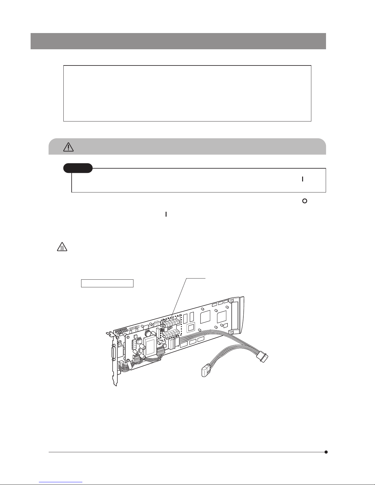
3. When handling the PCI interface board, be sure to hold it by the edge. Never touch the board surface directly, as this will
lead to malfunction.
The PC interface board area shown below becomes very hot during and immediately after use of the
camera. Be careful never to touch the area during and after use.
IMPORTANT
The DP30BW microscope digital camera is designed to be connected to a TV adapter mounted on an
Olympus UIS type optical microscope for use in quick recording of fluorescent images featuring easy
framing and focusing thanks to the high-sensitivity monochrome CCD and cooling using a Peltier device.
The DP30BW incorporates the background elimination function to record very low-fluorescence images
in high picture quality.
When the DP30BW microscope digital camera is used with a TV adapter or microscope from other
manufacturer than Olympus, the optical performance may not be manifested fully.
SAFETY PRECAUTIONS
Never connect or disconnect the interface cable while the main switch of the PC is set to “ ” (ON).
Otherwise, malfunction may result.
CAUTION
PCI interface board
Hot area
4. The camera head is as heavy as 3 kilograms. Be careful not to drop it when mounting or transporting it. Store it with the
C-mount section facing down because it tends to roll easily.
5. The camera head of the DP30BW incorporates the shutter. Since the shutter is a precision component, it should never be
touched by hand to prevent malfunction.
6. To prevent the microscope from toppling down, install the microscope on a horizontal surface. And avoid using microscope
attachments that may make the total height of the microscope above 1 meter when they are attached.
7. For the handling of the PC, please refer to the instruction manuals for your PC.

DP30BW
2
1
Conformity of the System
Restrictions
1. The recommended C-mount camera adapter is the combination U-TV1X-2 + U-CMAD3 or the U-TV0.5XC-2. (The
U-TV0.5XC should not be used because it deteriorates the image flatness.)
A TV adapter with a magnification below 0.5X cannot be used because it obscures part of the image.
2. When combination SZX + SZX-RFA (RFL) + SZX-BS + SZX-PHA is used, the DP30BW can be used only when it is
mounted on the port on the opposite side to the lamp housing.
When combination SZX + SZX-RFA (RFL) + SZX-TR30 is used, the DP30BW can be used only when a large stand or
illumination stand is used.
3. When a double-port type intermediate attachment (U-DP, U-TRU, etc.) is used, only the port coming on the optical axis can
be used.
4. When the U-TV0.5XC-2 is used together with a low-power objective (1.25X or 2X), the peripheral part of image may be
obscured unless the U-ULC-2 ultralow-magnification condenser is used.
5. When the DP30BW is connected to the rear port of the U-DPT or U-MPH, the peripheral part of the image may be
deteriorated due to the optical performance of the U-DPT or U-MPH.
6. When the U-CFU is used, it is required to set the exposure to a longer period than 1/30 sec. using the manual exposure
mode and adjust the brightness by engaging or disengaging ND filters.
7. Intermediate attachments:
When the U-TV0.5XC-2 is used, using two or more intermediate attachments* may obscure the peripheral part of the field
of view.
* Two intermediate attachments: BX51 + U-URA + U-CA or equivalent.
8. A commercially available C-mount lens can be used provided that it is designed for a 2/3 in. or larger CCD and the lens
projection from the C-mount area is less than 4.5 mm. However, Olympus does not guarantee the performance in this
case.
If a lens that does not employ a telecentric optics is used, problems due to optical adaptability such as shading may
occur.
Operating Environment
Temperature: 10 to 35°C (50 to 95°F). Humidity: 20 to 85% (without condensation).

3
Basic PC Operating Environment Recommendation
Machine PC/AT compatible - Pentium 4 type
CPU IntelR Pentium 4R, 1.3 GHz or more [Hyper-threading 2.6 GHz or higher recommended.]
Chipset IntelR i845*, i850*, i865*, i875* [i865 or after recommended]
RAM 512 MB or more [PC2700/PC3200 dual-channel DDR recommended]
HDD Free space 500 MB or more
Graphic Graphic RAM 16 MB or more
Graphic card of the AGP specification, capable of 32-bit color display of 1280 x 1024 or more
PCI bus PCI Rev. 2.1 or 2.2
OS Windows XP Professional or 2000 Professional
Drive CD-ROM (or CD-R/RW, etc.)
Main body Full-size PCI board compatible (See 2 below.)
Power supply 250 W or more (with CE marking)
1. PC model
<PC/AT compatible machine>: The PC should meet the above specifications. The recommended models are as follows:
DELL PRECISION series.
2. PCI interface board size
The PC should be a tower, middle-tower or desktop model capable of accepting a full-size PCI board. The board space
requirement is PCI Rev. 2.1 “full size x 1” + “half size x 1”.
(The slot for inserting the PCI board and a half-size space of the adjacent slot are required.)
The adjacent slot can be used to mount the trigger IO board.
3. CPU
Olympus does not guarantee operation if the PC uses a CPU other than Pentium 4 or a chipset other than an Intel
chipset.
4. PCI board installation in other slots
The PCI board can be used simultaneously with an SCSI card or LAN card.
It cannot be used simultaneously with the Video Capture card (because this occupies the PCI bus).
5. HD free space
The HD free space refers to the space that does not cause a special problem even when the system is installed or run.
The space required for saving an image file in the HDD is slightly more than 1.4 MB with a 1360 x 1024-pixel (8-bit)
non-compressed image. In consequence, the HDD should also provide a considerably large space for saving these
image files.
When recording a movie using an HDD stack, about 20 MB (at maximum) of HDD space is required per second and the
movie recording time is restricted according to the capacity remaining on the HDD.
6. Temporary movie save in the RAM
When the [Record till temporary memory is full] checkbox is checked on the DP Controller, a space of 70 MB is reserved
as the movie area in the physical memory. However, remember that about 20 MB (at maximum) of space per second
is necessary for recording a movie.
7. Graphic card
The maximum frame rate for the image (15 frames/sec.) may not be assured depending on the performance of the
graphic card used.
8. It is not permitted to install more than one set of PCI interface board (including the combination with the DP70 camera) in
a single PC. (This means that the PC cannot be used to control multiple cameras.)
9. The camera head of the DP30BW cannot be controlled using the PCI interface board for the DP70 camera.
It is neither possible to control the camera head of the DP70 using the PCI interface board for the DP30BW.
DP30BW
4
1. The camera head uses precision components. Handle it with care and avoid subjecting it to a sudden or severe impact.
2. The image displayed on the monitor may be affected when it is used near equipment generating strong electromagnetic
waves. This is not a malfunction and will not affect the actual image being recorded. To avoid interference during
operation, keep the system far from any source of electromagnetic waves.
3. When mounting the camera head on a tripod, attach it by using the DP-TRAD tripod adapter, which is separately available.
4. Do not use the camera in areas where it may be subjected to direct sunlight, high temperature and humidity, dust or
vibrations. For the operating environment conditions, see Chapter 8, “SPECIFICATIONS” on page 22.
5. Do not disassemble any part of the camera as this could result in malfunction or reduced performance.
3
Caution
If the camera system is used in a manner not specified by this manual, the safety of the user may be imperiled. In addition,
the camera may also be damaged. Always use the equipment as outlined in this instruction manual.
The following symbols are used to set off text in this instruction manual.
: Indicates that failure to follow the instructions in the warning could result in bodily harm to the
user and/or damage to equipment (including objects in the vicinity of the equipment).
# : Indicates that failure to follow the instructions could result in damage to equipment.
} : Indicates commentary (for ease of operation and maintenance).
Recorded picture data may be lost (or destroyed) in any of the following cases. Please note that
Olympus assures no liability for loss of recorded data. The user is recommended to back up the
recorded data periodically.
· Improper handling of the external storage device such as a FD, MD or HD by the user or a third
party.
· Unauthorized servicing buy the user or a third party.
· Result of disconnection of the interface cable or setting the PC main switch to “ ” (OFF) in the
middle of recording or erasure (including initialization) operation.
· General equipment failure.
2
Getting Ready
Data Storage Caution
5
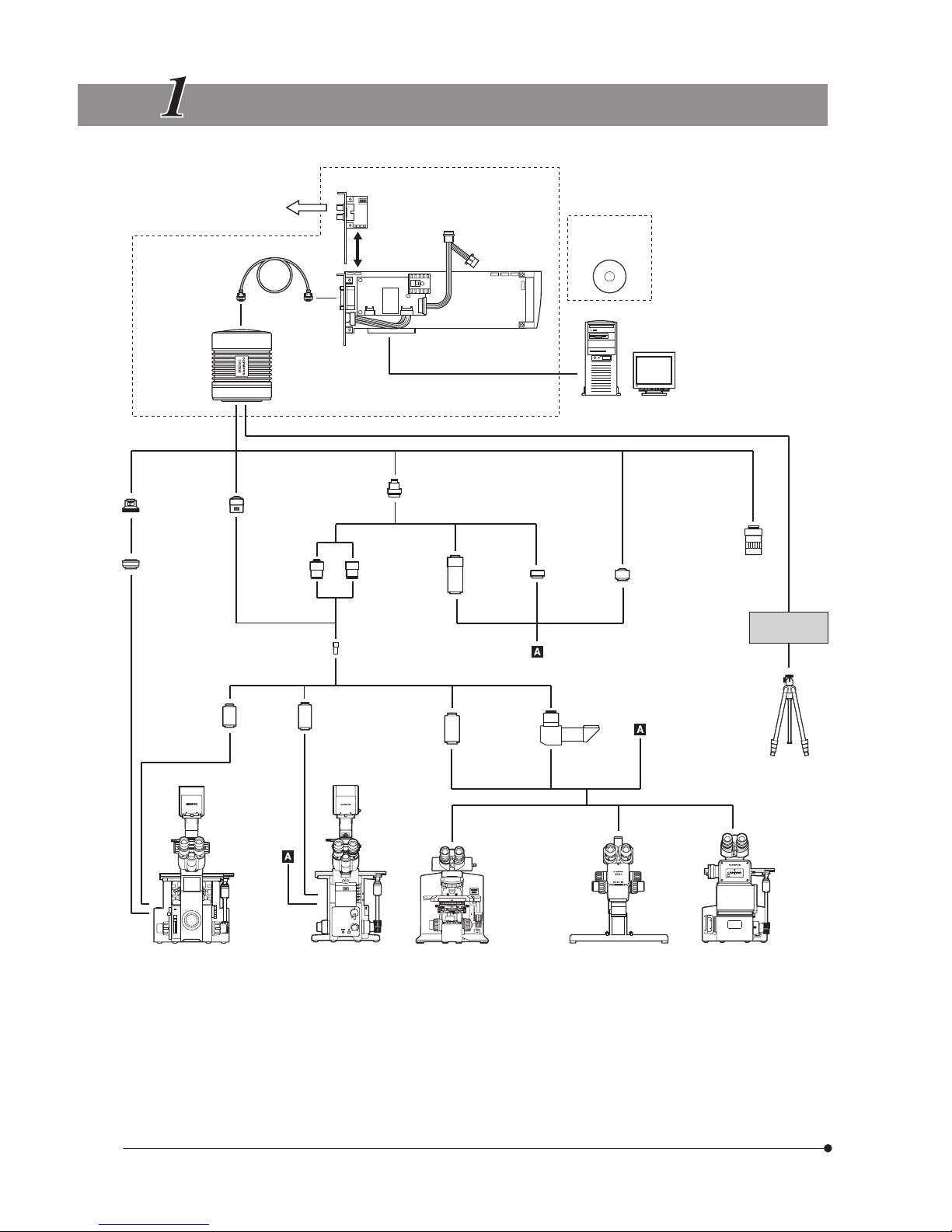
SYSTEM CHART
External shutter, etc.
(Model connected via BNC cable)
Trigger IO board
Cable
connection
ATX power supply
Microscope Digital
Camera
DP30BW
Interface cable
Camera head
PCI Interface board
Basic software
(CD-ROM)
DP-BSW
Computer
Monitor
U-CMT
C/T Mount
IX-TVAD
TV Adapter
U-PMTVC
C-Mount
TV Attachment
U-PMTV
TV
Attachment
U-PMTV1X
TV Attachment,
1X
U-CMAD3
C-Mount Camera
Adapter
U-TV0.5X
TV Adapter,
0.5X
U-TV1X-2
TV Adapter,
1X
U-TV0.5XC-2
C-Mount
TV Adapter, 0.5X
C-mount
lens
DP-TRAD
Tripod Adapter
Commercially
available tripod
IX-SPT
Straight
Photo Tube
IX2-SPT
Straight Photo
Tube for IX2
U-SPT
Straight
Photo Tube
U-DPT
Double-Port
Photo Tube
IX70/IX50
Inverted
Microscope
IX81/IX71/IX51
Inverted
Microscope
AX80/AX70
BX61/BX51/BX41
BX60/BX50/BX40
MX80/MX50/MX40
Erected
Microscope
SZX12/SZX9
Stereo
Microscope
GX71/GX51
Inverted
Metallurgical
Microscope
PE (2X˜)
Photo eyepiece

DP30BW
6
NOMENCLATURE
Camera Head
Any equipment connected to the camera head should be an Olympus-designated product or a
product in compliance with the requirements of IEC60950 or CISPR22-24. If equipment other
than these products is connected, Olympus cannot guarantee any performance of the camera.
Tripod adapter insertion slot (P. 8)
Tripod adapter mount screw
(P. 8)
Shutter
# A precision component that
should never be touched by
the user.
Connector (P. 9)
C-mount thread (P. 8)
PCI Interface Board
(PCI standard full-size board)
Connection cable connector
Connector (P. 7)
ATX power supply cable
Connect to the power supply
connector inside the PC.
Interface cable (P. 7, 9)
Trigger IO Board
External input connector
BNC type.
External output connector
BNC type.
Connection cable connector
Connection cable (P. 7)
PCI interface board <––> Trigger IO board.
Basic Software
DP-BSW (optional)
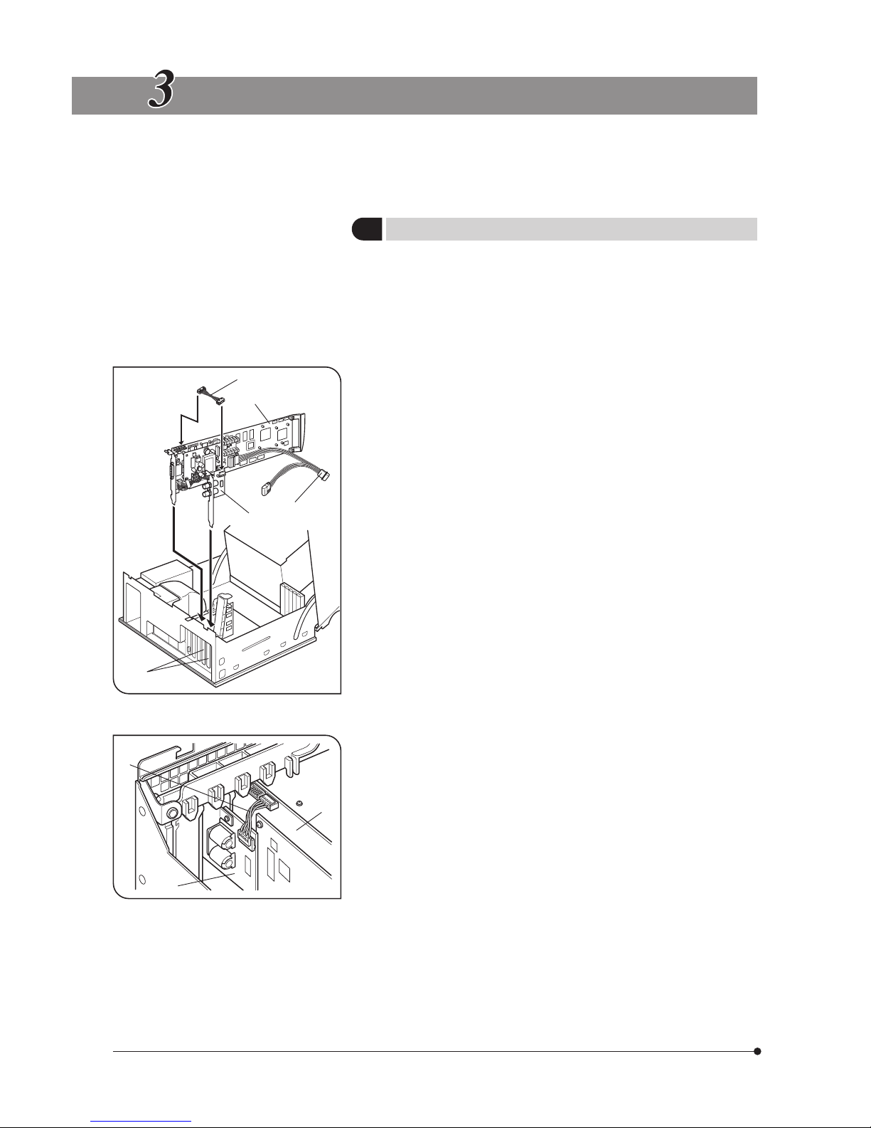
7
HARDWARE INSTALLATION
# Be sure to read the instruction manual for the PC in order not to
damage the PC and PCI interface board.
# Be sure to turn off the PC and peripherals and unplug their power
cords before installing the PCI interface board.
# To avoid damage due to static electricity, touch an unpainted metallic
surface of the PC with your hand to leak the static electricity from your
body before installation.
1. Open the cover of the PC’s main body.
2. Remove the clamping screw of the slot covers @ of an unused PCI slot
on the Motherboard and remove the two covers.
3. Insert the PCI interface board ² taking care not to touch the board
surface directly by hand.
4. Plug the ATX power supply cable connector ³ of the PCI interface board
² into an unused HDD power supply connector which is directly drawn
from the power supply inside the PC. If the PC in use does not have an
unused power supply connector, use the ATX power supply cable of the
PCI interface board ² as the branching cable.
5. Insert the Trigger IO board | into the slot to the right of the PCI interface
board ².
6. Connect boards ² and | with the connection cable ƒ.
After confirming that the board is inserted and connected securely,
attach the slot cover using the clamping screw removed above.
7. Attach the PC cover to the original position.
8. Connect the interface cable to the connector on the PCI interface board
and tighten the connector lock screws. Check that the interface cable
does not slip out.
1
Installing the Boards
(Figs. 1 & 2)
Fig. 1
Fig. 2
@
²
³
|
ƒ
²
|
ƒ
 Loading...