

Page 1
Modules described in this manual
BXFMA-F
U-FH
U-IFFH
U-BI30-2, U-TR30-2, etc.
U-LH100-3
INSTRUCTIONS
BXFMA
MOTORIZED ILLUMINATION SYSTEM
WITH MOTORIZED FOCUSING UNIT
This instruction manual is for the Olympus Motorized Illumination System with Motorized Focusing
Unit, Model BXFMA. To ensure the safety, obtain optimum performance and to familiarize yourself
fully with the use of this system, we recommend that you study this manual thoroughly before
operating the system. Retain this instruction manual in an easily accessible place near the work
desk for future reference.
This publication is printed on 100% recycled paper
A X 7 6 1 5
Page 2

Page 3
BXFMA
CONTENTS
Correct assembly and adjustments are critical for the microscope to exhibit its full performance. If you are going to
assemble the microscope yourself, please read Chapter 8, “ASSEMBLY” (pages 23 to 28) carefully.
IMPORTANT — Be sure to read this section for safe use of the equipment. —
1 SYSTEM DIAGRAM
2 NOMENCLATURE
3
REFLECTED LIGHT BRIGHTFIELD/DARKFIELD OBSERVATION PROCEDURE
4 USING THE CONTROLS
4-1 Power Supply Unit TH4 .............................................................................................................................................................. 10
4-2 Motorized Illuminator with Motorized Focusing Unit BXFMA-F ............................ 10-13
1 Selecting the Observation Light Path 2 Centering the Field Iris Diaphragm (FS)
3
Centering the Aperture Iris Diaphragm (AS)
5 Using the Filters
4-3 Observation Tube ...................................................................................................................................................................... 14-15
1 Adjusting the Interpupillary Distance 2 Adjusting the Diopter
3 Using the Eye Shades 4 Using Eyepiece Micrometer Disks
5 Selecting the Light Path of Trinocular Observation Tube
6 Adjusting the Tilt
4-4 Differences in Operating Procedures of Software BX2-BSW ............................................ 16
1-2 Setting Procedure BX2-BSW Help
4 Adjusting the Motorized Focusing Unit
1-3
4
5-7
8-9
10-16
5 TROUBLESHOOTING GUIDE
6 SPECIFICATIONS
7 OPTICAL CHARACTERISTICS <<UIS2 (UIS) Series>>
8
ASSEMBLY
—
See this section for the replacement of the light bulb. —
17- 18
19
20-22
23-28
Page 4

Page 5
IMPORTANT
The BXFMA-F motorized illuminator with motorized focusing unit can be installed in a user’s system in
combination with the BX-UCB control box as well as a PC (running the BX2-BSW software) or the
U-HSTR2, U-FH focus adjustment knob unit and U-IFFH focus adjustment knob interface.
The instructions for the BX/UCB/U-HSTR2 and software (BX2-BSW, commands) are provided in separate
instruction manuals. Please also refer to these manuals as required.
Motorized Controls
Configuration of Instruction Manuals
This motorized illuminator can manifest its functions when it is combined with other modules. The instructions
manuals for the following modules are prepared separately to the present instruction manual. Please read the
manuals according to your own system.
Manual Name Main Contents
BX-UCB/U-HSTR2
· BF (brightfield)/DF (darkfield) switching operation
· AS (aperture iris diaphragm) opening/closing operation
· Focus adjustment operation
Functions of the Control Box (incorporating the power supply)
and Hand Switch
BXFMA
BX2 Software for PC (CD-ROM)
BX2-BSW Ver. 03.01 or higher
TH4 External halogen lamp power supply
U-FWT/FWR/FWO Motorized filter wheels (Only the U-FWR can be used in this system.)
Methods of PC control of functions
# Normal operation is not available unless the specified software is used.
Precautions When Unpacking the Microscope
}To prevent deterioration in performance during transport, the illuminator is shipped with transport lock applied to the
focusing unit, observation method switch and aperture iris diaphragm (AS) mechanism, Be sure to release the transport
lock of these three modules before assembly, and engage the transport lock before the next transport of the illuminator.
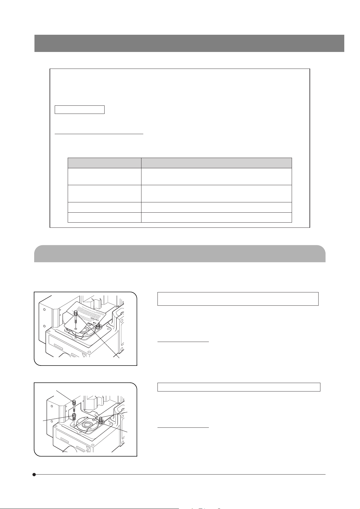
Releasing the Transport Lock of the Observation Method (BF/DF)
Switch Mechanism (Fig. 1)
Turn the lock knob 1 counterclockwise to loosen it, and remove it together
with the caution tag.
}Retain the lock knob carefully because it will be used again the next time
the equipment is transported.
To set transport lock:
1. Switch the observation method to DF (reflected light darkfield).
2. Turn the lock knob all the way clockwise.
@
³
²
Fig. 1
Fig. 2
²
³
Releasing the Transport Lock of the Focusing Unit Mechanism (Fig. 2)
1. Turn the two lock knobs 2 counterclockwise to loosen and remove them.
2. Similarly to step 1, turn the two lock screws 3 to remove them.
}Retain the lock knobs and lock screws carefully because they will be
used again the next time the equipment is transported.
To set transport lock:
1. Raise the focusing unit to the higher limit position.
2. Turn the two lock screws all the way clockwise.
3. Similarly to step 2, turn and tighten the too lock knobs.
1
Page 6
@
SAFETY PRECAUTIONS
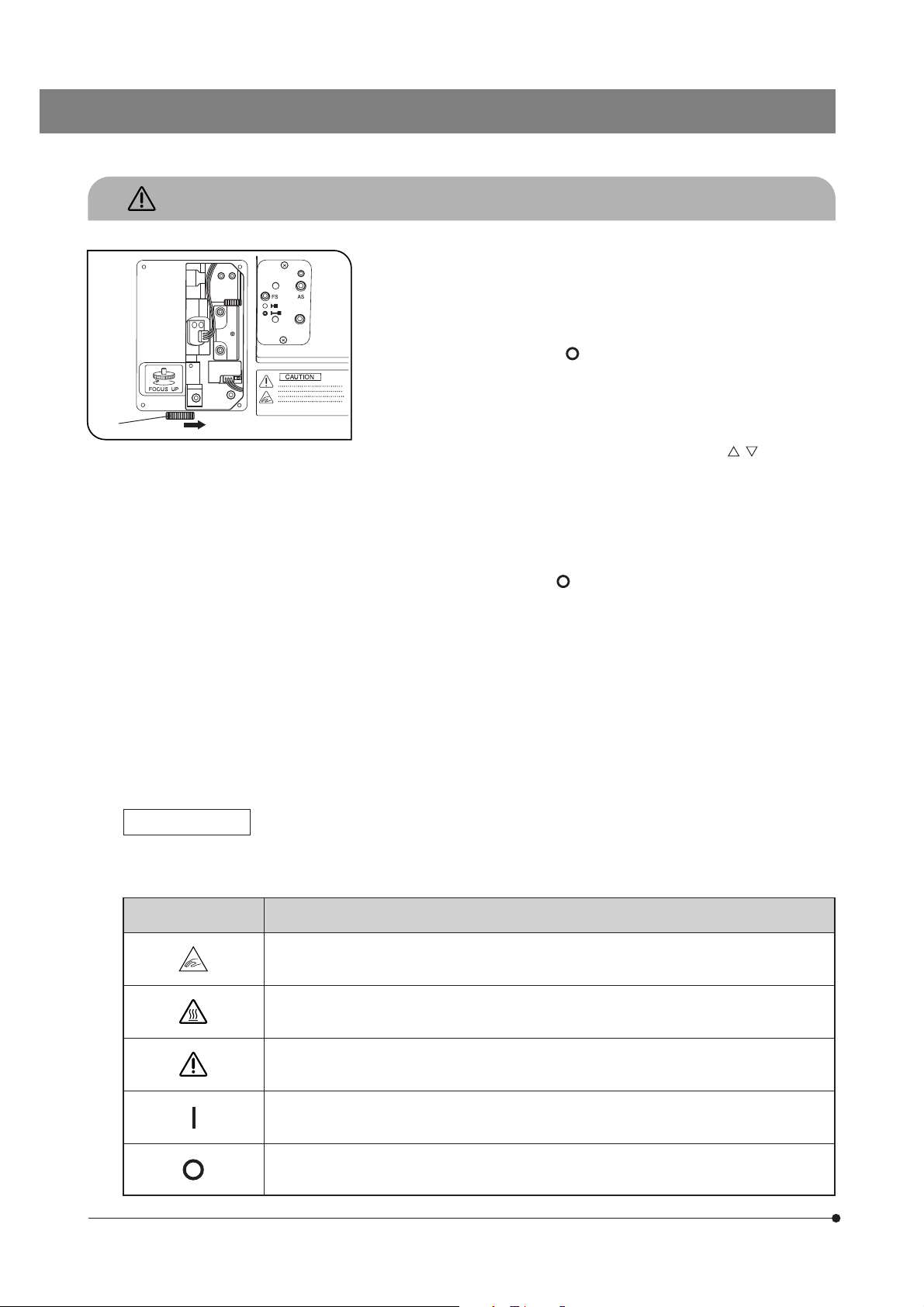
Fig. 3
1. Keep your hands apart from the revolving nosepiece during focusing
operation and while the main switch of the BX-UCB control box is set to
“ I ” (ON). If your finger is caught by the up/down movement of the revolving
nosepiece, an injury such as bone fracture my result.
Should your finger be caught by the revolving nosepiece, lower it with the
following method:
· Set the main switch to “ ” (OFF), remove the right side panel of the
illuminator using a Phillips screwdriver and turn the manual knob 1 inside
the panel in the opposite direction to the direction shown in the figure (i.e.
clockwise) to lower the revolving nosepiece. (Fig. 3)
2. Emergency stop of focus operation is possible by turning the focus
adjustment knob on the microscope frame or on the U-FH (in either
direction), or by pressing the FOCUS control button ( , , F/C or ESC),
after focus operation has been activated (except when data is being
downloaded to a PC).
When the BX-UCB control box’s main switch is set to “ I ” (ON), the focus
operates automatically (the objective raises once and then returns to the
original position) for initialization. (It takes about 20 seconds.)
If the above emergency procedure is performed during this automatic
focus operation, the microscope stops operating. Should this happen,
set the main switch to “ ” (OFF) and then “ I ” (ON) again.
3. The surface of the lamp housing on the side of the illuminator becomes
very hot. When installing the system, leave spaces of more than 10 cm
around, particularly above the lamp housing.
4. Be careful not to touch the lamp housing when centering the aperture
iris diaphragm or controlling the field iris diaphragm. You run the risk of
burn if you touch the lamp housing while the lamp is lit or immediately
after it is turned off.
5. Route the connection cables away from the lamp housing. Should a
cable comes in contact with the hot lamp housing, the cable could melt
and cause electric shock.
6. When installing the illuminator in an existing system, insert 6 bolts in the
module installation screw holes and tighten firmly.
2
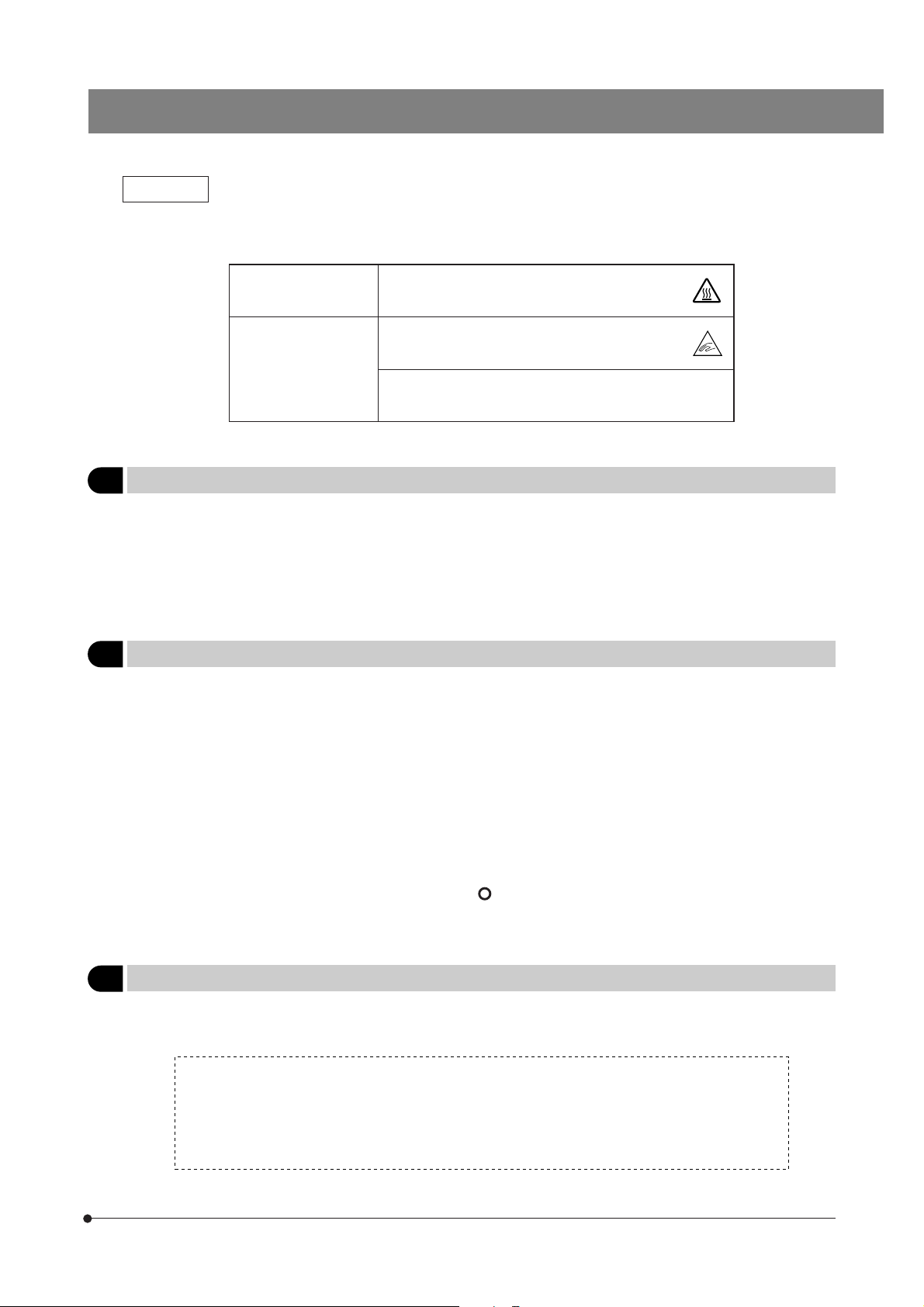
Safety Symbols
The following symbols are found on the motorized illumination system. Study the meaning of the symbols and always
use the equipment in the safest possible manner.
Symbol Explanation
Be careful not to have your finger or hand caught (between the revolving nosepiece and illuminator
or between the specimen and objective).
Indicates that the surface becomes hot, and should not be touched with bare hands.
Before use, carefully read the instruction manual. Improper use could result in personal injury to
the user and/or damage to the equipment.
Indicates that the main switch is ON.
Indicates that the main switch is OFF.
Page 7
BXFMA
Warnings
Warning engravings/sticklers are placed at parts where special precaution is required when handling and using the
system. Always heed the warnings.
Warning engraving
positions
Warning sticker
positions
Lamp housing
(U-LH100L-3, U-LH100-3)
Motorized illuminator
BXFMA-F
Active AF unit
U-AFA1M
(High Temperature
warning )
(Finger injury
warning)
(Laser warning)
1 Getting Ready
1. The illuminator is a precision instrument incorporating motorized parts. Always install it horizontally (it is inhibited to install
it on the side panel), handle it with care and avoid subjecting it to sudden or severe impact.
2. Do not use the system where it is subjected to direct sunlight, high temperature and humidity, dust or vibrations. (For
operating conditions, see Chapter 6, “SPECIFICATIONS” on page 19).
3. Only one intermediate attachment can be used, by installing the U-AFA1M active AF unit, U-CA magnification changer or
U-EPA2 eye point adjuster above the motorized illuminator.
2 Maintenance and Storage
1. To clean the lenses and other glass components, simply blow dirty away using a commercially available blower and wipe
gently using a piece of cleaning paper (or clean gauze).
If a lens is stained with fingerprints or oil smudges, wipe it gauze slightly moistened with commercially available absolute
alcohol.
!Since the absolute alcohol is highly flammable, it must be handled carefully.
Be sure to keep it away from open flames or potential sources of electrical sparks –– for example, electrical
equipment that is being switched on or off.
Also remember to always use it only in a well-ventilated room.
2. Do not attempt to use organic solvents to clean the non-optical components of the microscope system. To clean them,
use a lint-free, soft cloth slightly moistened with a diluted neutral detergent.
3. Never attempt to disassemble any part of the microscope system.
4. When not using the microscope, set the main switch to “
cover the microscope with a dust cover before storage.
5. When disposing of this product, check the regulations and rules of your local government and be sure to observe them.
” (OFF), wait until the lamp housing has cooled down, and
3 Caution
If the system is used in a manner not specified by this manual, the safety of the user may be imperiled. In addition, the
equipment may also be damaged. Always use the equipment as outlined in this instruction manual.
The following symbols are used to set off text in this instruction manual.
!: Indicates that failure to follow the instructions in the warning could result in bodily harm to the
user and/or damage to equipment (including objects in the vicinity of the equipment).
# : Indicates that failure to follow the instructions could result in damage to equipment.
} : Indicates commentary (for ease of operation and maintenance).
3
Page 8
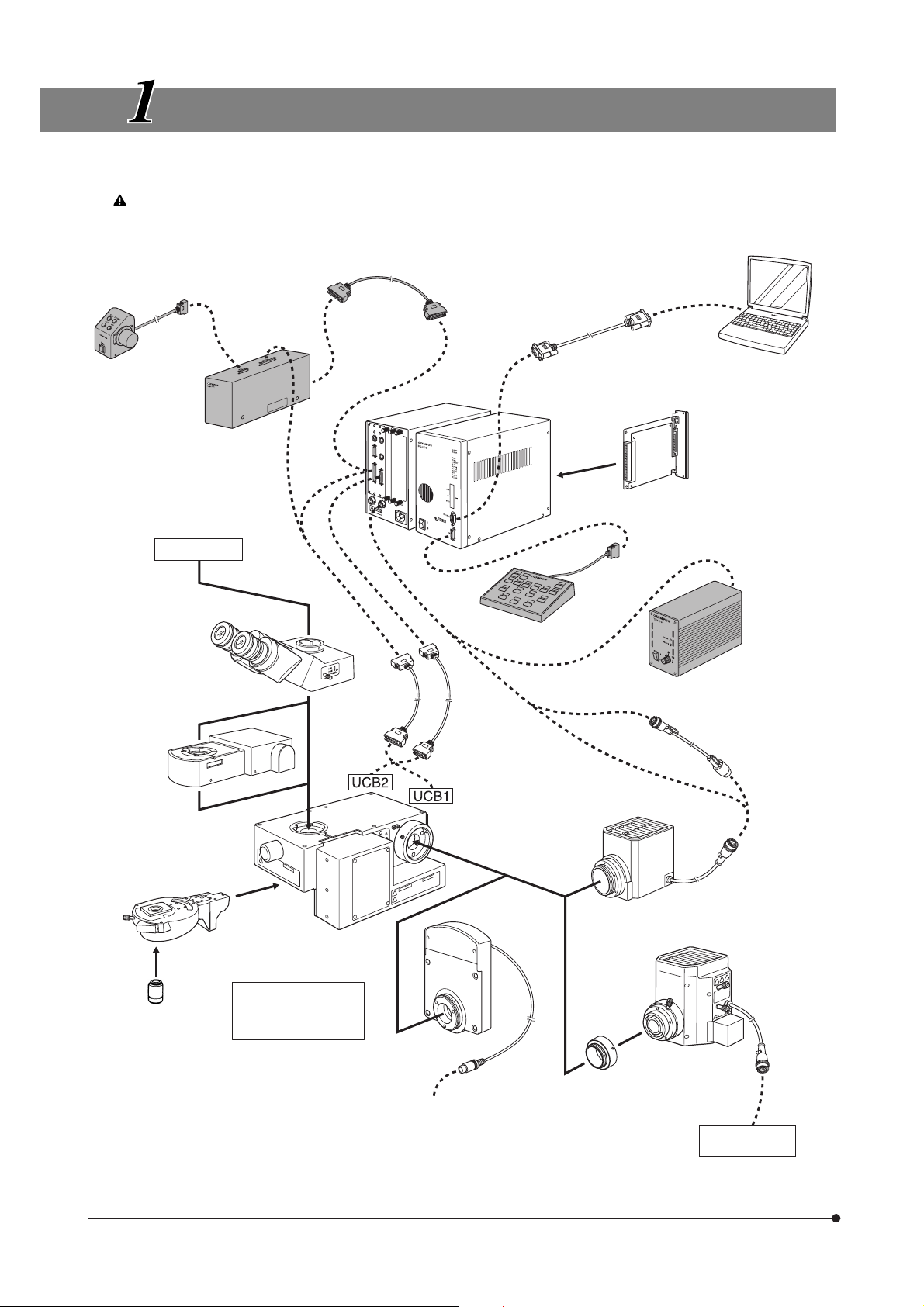
SYSTEM DIAGRAM
}The modules marked * are not required when a PC is used to control all operations from the PC.
The PC used in this system should meet the requirements by IEC60950. Be sure to use an Olympus-designated
connection cord. If a non-designated connection cord is used, Olympus cannot guarantee any performance of the
system.
Focus Adjustment
Knob Unit
*
U-FH
Focus Adjustment
Knob Interface
*
U-IFFH
TV system
Connection cable
(50-pin)
(Rear panel)
*
RS232C cable
Control Box
BX-UCB
Z-Board
U-ZPCB(T2)
AF Board
U-AFA1-CB
PC
(BX2-BSW
installed)
Observation tube
· U-BI30-2
· U-TR30-2
· U-TBI3
· U-TUL, etc.
Active AF Unit
U-AFA1M
Motorized Revolving
Nosepiece
· U-D5BDREMC
· U-D6REMC
· U-P5REMC
· U-D5BDREM
· U-D6REM
Objective
Connection
cable
(50-pin)
Motorized Illuminator
with Motorized
Focusing Unit
BXFMA-F
Surface for installation
on system:
· Bottom panel
· Left side panel
Connection
cable
(36-pin)
Filter Wheel
U-FWR
Hand Switch
U-HSTR2
*
100 W Halogen
Lamp Housing
· U-LH100-3
· U-LH100L-3
(Note)
Power Supply
Unit
*
TH4
Extension Cord
U-RMT
High-Intensity
Lamp Housing
· U-LH100HG
· U-LH100HGAPO
· U-LH50MH
· U-LH75XEAPO
4
Auxiliary ring
(provided with the
Connect to FW1, 2 or 3
()
of BX-UCB
BXFMA-F)
Special power
supply
(Note) The cable of the U-FWR filter wheel runs close to the lamp housing when the filter wheel is attached.
Position the cable so that it does not come in contact with the lamp housing.
Page 9
BXFMA
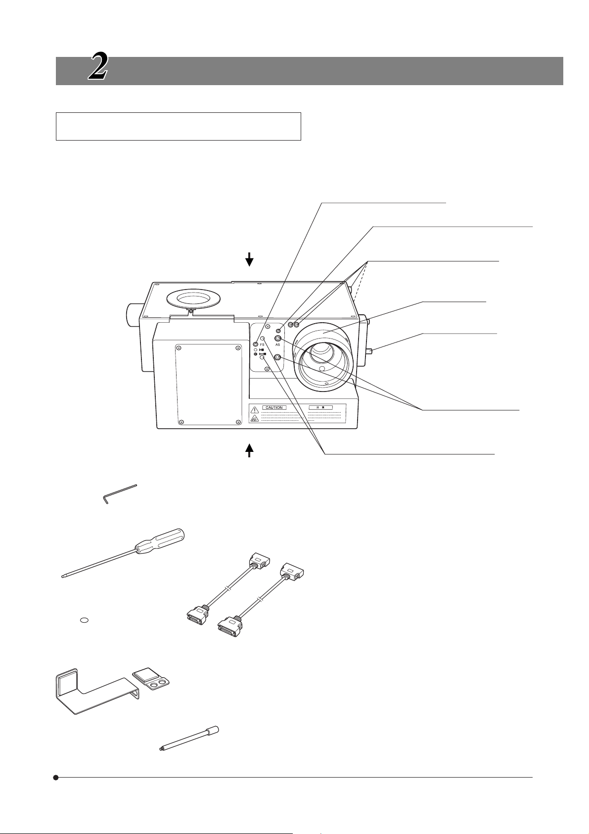
NOMENCLATURE
Motorized Illuminator with Motorized Focusing Unit
BXFMA-F
}The observation method (BF/DF) switching, aperture iris diaphragm opening/closing and focus adjustment (which can also
be controlled using the U-FH focus adjustment knob unit) can be controlled using the BX2-BSW software run on the PC.
Field iris diaphragm lever (Page 11)
Aperture iris diaphragm lock screw (Page 11)
Surface for installation on system
(Left side panel)
AF support bracket clamping screws
(x 4)
(Note 1)
Auxiliary ring
Filter slider (Page 13)
Allen wrench (1.5 mm)
Allen screwdriver (3 mm)
Seals (x 6)
Aperture iris diaphragm
centering screws (Page 11)
Field iris diaphragm centering screws (Page 10)
Surface for installation on system
(Bottom panel)
(Note 1) The auxiliary ring is for use with the high-
intensity lamp housing. When the halogen
lamp housing is used, remove the ring by
loosening the 2 clamping screws using the
Allen screwdriver.
(36-pin)
(50-pin)
Connection cable
AF support brackets
(Page 28)
Field iris diaphragm auxiliary lever
(Detachable)
5
Page 10
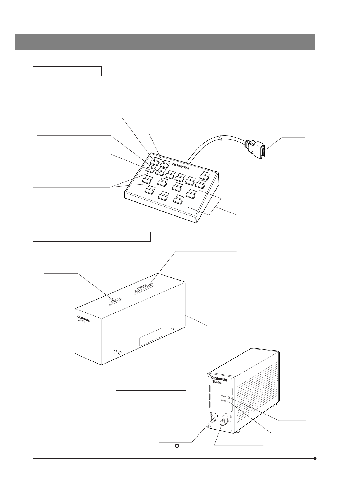
Hand Switch U-HSTR2
}The button functions shown below refer to those in the standalone operation.
The button functions can be set arbitrarily when PC control (remote control) is used.
For other operating instructions, refer to the BX-UCB/U-HSTR2 instruction manual.
BF (Brightfield) button
AS+ (Aperture iris diaphragm open)
button
AS– (Aperture iris diaphragm close)
button
Projections for blind-touch operation
Focus Adjustment Knob Interface U-IFFH
U-FH connector
DF (Darkfield) button
UCB1 (illuminator) connector
Connector
Objective buttons
6
Power Supply Unit TH4
}For details, refer to the separate
instruction manual.
Main switch
I : ON. : OFF.
BX-UCB connector
POWER LED
REMOTE LED
Light intensity control
Page 11
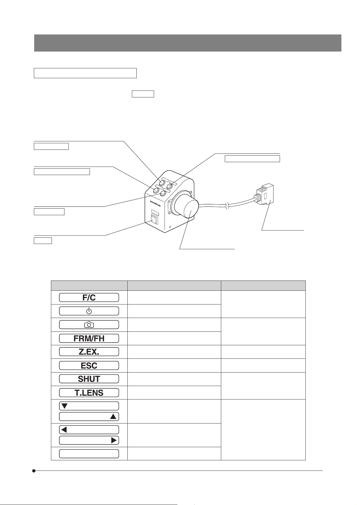
Focus Adjustment Knob Unit U-FH
The button functions shown below refer to those in the standalone operation.
The button functions indicated inside are the initial settings in the control from a PC running the BX2-BSW software.
The button functions in PC control can also be set arbitrarily. For their allocation, refer to the tutorial or help of the BX2-BSW
software (Ver. 03.01 or higher).
After deciding the button functions, attach the provided function name stickers near the buttons.
For the abbreviations and symbols, refer to the table at the bottom of this page.
Objective escape/return button (Page 12)
Lamp ON/OFF
Fine/Coarse switch button (Page 12)
Focusing motor ON/OFF
Objective Down button (Page 12)
F/C selector
Objective Up button (Page 12)
Objective escape/return
BXFMA
Transmitted/reflected light switch
button*
Option
* If the halogen bulb does not light up, press this button once.
Abbreviation or Symbol Function Remark
Fine/Coarse switching
Lamp ON/OFF
Photo voltage ON/OFF
Focus adjustment frame/U-FH
Z-focusing motor ON/OFF OFF for electrical noise reduction
Objective escape/return
Shutter IN/OUT
Condenser top lens IN/OUT
Connector
Connect to U-IFFH.
Focus adjustment knob
Not used with the BXFMA.
Not used with the BXFMA.
Up/down operation such as light intensity or objective height adjustment
Left/right operation such as mirror unit
or filter wheel movement
Write the applicable functions in the
blank areas using an oil-ink pen.
7
Page 12

REFLECTED LIGHT BRIGHTFIELD/DARKFIELD
OBSERVATION PROCEDURE
}The following flow chart pertains to the reflected light brightfield/darkfield observations.
The controls used for a system using the U-HSTR2 hand switch, U-FH focus adjustment knob unit and TH4 power supply
unit for halogen bulb together with those used for a PC-controlled system.
For details on the PC control, also refer to the tutorial or help provided with the BX2-BSW software.
(Non PC Controlled System) (PC Controlled System)
Set the main switch to “ I ” (ON).
Select BF (brightfield) or DF
(darkfield).
Select the light path (when a trinocular tube is used).
Place the specimen on the specimen table.
Engage the 10X objective in the
light path.
Bring the specimen in focus.
Adjust the brightness. 9Light intensity adjustment knob 3PC command
Adjust the interpupillary distance.
Adjust the diopter.
1BX-UCB main switch “ I ” (ON)
2TH4 main switch “ I ” (ON)
4BF/DF button (Page 10) 3PC command
5
Light path selector knob (Page 15)
6Revolving nosepiece button 3PC command
7Objective Up/Down buttons, or
8Focus adjustment knob
aBinocular sleeves (Page 14)
b
Diopter adjustment ring (Page 14)
1Main switch “ I ” (ON)
3PC “ I ” (ON)
5
Light path selector knob (Page 15)
3PC command
aBinocular sleeves (Page 14)
b
Diopter adjustment ring (Page 14)
Adjust the aperture iris and field
iris diaphragms.
}In DF observation, both should
be opened fully.
Engage the objective to be used
in the light path and bring the
specimen in focus.
Start observation.
8
cAS+/– buttons (Page 11)
dField iris diaphragm auxiliary
lever (Page 11)
6Revolving nosepiece button
7Objective Up/Down buttons or
8Focus adjustment knob
Engage the required
filters.
Adjust the brightness. 9Light intensity adjustment knob 3PC command
eFilter insertion slot (Page 13) eFilter insertion slot (Page 13)
3PC command
dField iris diaphragm auxiliary
lever (Page 11)
3PC command
3PC command
Page 13

}The modules marked * are not required when a PC is used to control all operations from the PC.
e
a
5
d
b
BXFMA
Motorized Illuminator with
Motorized Focusing Unit
BXFMA-F
Motorized Revolving
Nosepiece
Focus Adjustment
Knob Interface
U-IFFH
*
7
Focus Adjustment
Knob Unit
U-FH
2
Power
Supply Unit
TH4
*
9
Control Box
BX-UCB
4
@
c
Hand Switch
U-HSTR2
*
8
6
*
PC
3
} Make a photocopy of the observation procedure pages and post it near your microscope.
9
Page 14

USING THE CONTROLS
4-1 Power Supply Unit TH4
}Please also refer to the separate instruction manuals. Note that, when the BX-UCB control box is used to supply the lamp
power, the brightness should be controlled from the PC.
4-2 Motorized Illuminator with Motorized Focusing Unit BXFMA-F
}The following description deals with the standalone operations in the system without using a PC.
³
@
4
6
Fig. 4
Fig. 5
²
5
7
1 Selecting the Observation Light Path
Press the BF button 1 or DF button 2 of the hand switch to set the
mirrors for the desired observation system.
BF: Reflected light brightfield light path
DF: Reflected light darkfield light path
2 Centering the Field Iris Diaphragm (FS)
}Since the field iris diaphragm is usually used in the fully open condition,
the illuminator employs a method in which the auxiliary lever 4 is inserted
as required.
1. Press the BF button 1 of the hand switch to select the reflected light
brightfield light path.
2. Press the objective button 3 of the hand switch to engage the 10X
objective in the light path, place the specimen on the specimen table
and bring the specimen into approximate focus.
3. Screw the field iris diaphragm auxiliary lever 4 into the illuminator and
pull the lever to stop down the field iris diaphragm.
4. Insert the Allen screwdriver, provided with the illuminator, into each of the
two FS centering screws 5 and turn them until the field iris diaphragm
image becomes concentric with the field iris.
5. While pushing in the field iris diaphragm auxiliary lever 4, open the field
iris diaphragm until the field iris diaphragm image is inscribed with the
field of view. If their centers are deviated, center the field iris diaphragm
again.
6. Open the field iris diaphragm until the field iris diaphragm image circumscribes (becomes the same size as) the field of view.
(Figs. 4 & 5)
(Fig. 4)
10
Page 15

BXFMA
9
8
@
Field iris diaphragm image
Eyepiece field of view
Using the Field Iris Diaphragm
{In reflected light brightfield observation:
The field iris diaphragm adjusts the illuminated area in order to obtain
high-contrast images.
Adjust the field iris diaphragm auxiliary lever 4 of the illuminator according
to the objective in use so that the field iris diaphragm image circumscribes
the field of view and block penetration of excess light in the field.
{In reflected light darkfield observation:
Always open the field iris diaphragm fully by pushing in the field iris
diaphragm auxiliary lever 4 all the way.
3
Centering the Aperture Iris diaphragm (AS)
# The aperture iris diaphragm is locked by a lock screw 6 (Fig. 5) on the
illuminator. Be sure to unlock it by loosen the screw using the Allen
screwdriver (3 mm), provided with the illuminator, before proceeding
to centering.
After completing centering, be sure to lock the diaphragm again to
prevent its malfunction.
1. Press the BF button 1 of the hand switch to select the reflected light
brightfield light path.
2. Press the objective button 3 (Fig. 4) of the hand switch to engage the
10X objective in the light path, place the specimen on the specimen
table and bring the specimen into approximate focus.
}It is recommended to use a highly reflective specimen such as a mirror
to facilitate viewing the aperture iris diaphragm image.
3. Remove an eyepiece, look into the eyepiece sleeve and press the ASbutton 8 of the hand switch to stop down the aperture iris diaphragm to
about 70% opening.
4. If the center of the aperture iris diaphragm is deviated, insert the Allen
screwdriver into the two AS centering screws 7 (Fig. 5) and adjust them
to center the aperture iris diaphragm.
(Figs. 4 to 6)
Fig. 6
70%
30%
Aperture iris diaphragm image
Using the Aperture Iris Diaphragm
{In reflected light brightfield observation:
In general, optimum observation is possible by controlling the aperture
iris diaphragm to between 70% and 80% of the aperture number of the
objective.
{In reflected light darkfield observation:
Always open the field iris diaphragm fully by pushing the AS+ button 9.
}With certain specimens, images with high contrast and little flare can be
observed by stopping down the aperture iris diaphragm below the standard aperture.
11
Page 16

4 Adjusting the Motorized Focusing Unit
#Make sure that the specimen is located near the standard focusing
position (see diagram on page 25).
}Motorized focusing control is available using a PC or the U-FH focus
adjustment knob unit.
@
|
Fig. 7
Fig. 8
³
²
²
@
³
Using the U-FH Focus Adjustment Knob Unit (Fig. 7)
· F/C button 1
This button switches the objective adjustment movement caused by turning the focus adjustment knob between Fine and Coarse movements.
}For safety, the initial position that is set automatically when the main
switch of the BX-UCB control box is set to “ I ” (ON) is “F”.
Fine adjustment: 0.1 mm per turn
Coarse adjustment: 1 mm per turn
· Objective Up button 2/Down button 3
Press either button to raise or lower the objective.
# When pressing the objective Down button, take care against collision
between the objective and specimen.
· Objective escape/return button 4
Before replacing the specimen, press this button to cause the objective
escape. Pressing the button again causes the objective return to the
original position.
Objective Lower Hardware Limit Adjustment (Fig. 8)
-- Adjust the lower hardware limit using the following procedure. --
?The lower hardware limit of the objective has been set to the lower limit
of the stroke before the system left the factory.
!During adjustment, do not approach your hand to the motor drive
mechanism so that your finger does not be caught by it.
#The lower hardware limit determines the lower limit of the objec-
tive to prevent it from collide with the specimen. As a result, note
that there is a risk of collision with specimen or reaching the lower
limit before the focusing position when the specimen is not flat, the
specimen thickness is changed or the WD (Working Distance) of
the objective in use is 1 mm or less.
#Always use the procedure described below. Otherwise, it will not
be possible to avoid collision of the objective with the specimen
perfectly.
#During adjustment, do not touch any electronic part to avoid its static
destruction.
#During adjustment, do not touch the motor mechanism or electronic
part to avoid their malfunction.
1. Set the main switch of the control box to “ I ” (ON).
2. Remove the side panel of the illuminator by removing the screws using a
Phillips screwdriver.
3. Among the objectives mounted on the revolving nosepiece, engage the
one with the shortest WD in the light path.
12
Page 17

BXFMA
4. Approach the objective to the specimen until the height you want to set
as the lower hardware limit height.
5. Loosen the limit position clamping screw 1 using the provided Allen
wrench (width across flats 1.5 mm).
6. Turn the limit position adjustment knob 2 until the LED 3, which has
been OFF, turns ON.
7. Tighten the limit position clamping screw 1 using the Allen wrench (width
across flats 1.5 mm).
3
4
|
³
²
Fig. 9
Fig. 10
@
5 Using the Filters
}Filters (Up to two filters*) can be inserted in the filter slider, which can be
engaged in or disengaged from the light path using a knob 1.
* The two filters are always engaged or disengaged together.
Inserting the Filters
1. Using the Allen screwdriver, loosen and remove the screws 2 clamping
the filter slider.
2. Take out the push ring 3 from the filter slider, place the desired filter(s) 4
and hold the filter(s) with the push ring.
3. Attach the filter slider to the original position.
Applicable Filters and Their Purposes
Applicable Filter
32LBD
32IF550 Green filter for giving contrast to a monochrome image.
32ND25 Light adjustment filter.
32ND6 Light adjustment filter
32FR
Color temperature conversion filter for turning the illumination light to daylight.
For use in general observation or color photomicrography.
For use in monochrome photomicrography.
(Transmittance 25%)
(Transmittance 6%)
Frost filter obtaining regular illumination field, though the
brightness is reduced slightly.
Purpose
(Figs. 9 & 10)
13
Page 18

4-3 Observation Tube
²
Fig. 11
Fig. 12
@
1 Adjusting the Interpupillary Distance
While looking through the eyepieces, adjust for binocular vision until the
left and right fields of view coincide completely. The index dot · indicates
the interpupillary distance.
}Note your interpupillary distance so that it can be quickly duplicated.
2 Adjusting the Diopter
1. Looking through the eyepiece without the diopter adjustment ring, rotate
the focus adjustment knob to bring the specimen into focus.
2. Looking through the eyepiece with the diopter adjustment ring 1, turn it
to focus on the specimen. (Fig. 12)
(Figs. 12 & 13)
(Fig. 11)
Fig. 13
Fig.14
Using a Finder Eyepiece
1. Looking through the right eyepiece with your right eye, turn the diopter
adjustment ring 2 at the top of the eyepiece until clearly defined double
crosslines can be seen in the field of view. (Figs. 12 & 13)
2. Looking through the right eyepiece, rotate the focus adjustment knobs to
bring the specimen and double crosslines into simultaneous focus.
3. Looking through the left eyepiece with your left eye, turn the diopter adjustment ring 1 to focus on the specimen.
Using an Super Widefield Observation Tube
The operation is basically identical to the above. However, as the left
eyepiece of the super widefield tube does not have the diopter adjustment
ring, focus on the specimen by turning the top of the left eyepiece.
3 Using the Eye Shades
When Wearing Eyeglasses
Use with the eye shades in the normal, folded-down position. This will
prevent the eyeglasses from being scratched.
When Not Wearing Eyeglasses
Extend the folded eye shades in the direction of the arrow to prevent
extraneous light from entering between the eyepieces and eyeglasses.
(Fig. 14)
14
Page 19

BXFMA
Fig. 15
Fig. 16
@
²
@
4 Using Eyepiece Micrometer Disks
Eyepiece micrometer disks can be inserted into the WHN10X-H (or
WHN10X) eyepieces.
However, if the eyepiece does not have the helicoid adjustment facility
and your eyesight is poor, you may have difficulties in focusing on the
eyepiece micrometer disk. In this case, it is recommended to look into
the eyepiece through your eyeglasses.
Use 24 mm dia. x 1.5 mm thick micrometer disks.
Following Fig. 15, unscrew the micrometer mounting frame 2 from the
eyepiece and place a micrometer disk 1 into the mounting frame. Reattach the micrometer mounting frame in the original position.
5
Selecting the Light Path of Trinocular Observation Tube
Slide the light path selector knob 1 to select the desired light path.
Trinocular
Tube
U-TR30-2
U-SWTR-3
U-ETR3
U-SWETR
U-SWETTR2 Binocular 100%
Pushed in Middle position Pulled out
Binocular 100%
Binocular 100% TV, photo 100%
Light Path Selector Position
Binocular 20%
TV, photo 80%
TV, photo 100%
Binocular 20%
TV, photo 80%
(Fig. 15)
(Fig. 16)
Fig. 17
6 Adjusting the Tilt
}Adjust the height and tilt of the observation tube to obtain the most com-
fortable viewing position.
Holding the binocular section with both hands, raise or lower it to the
desired position.
# Never attempt to force the binocular section past the upper or lower
stop position. Applying excessive force could destroy the limiting
mechanism.
# The U-TBI3 cannot be used in combination with any intermediate
attachment.
(Fig. 17)
15
Page 20

4-4 Differences in Operating Procedures of Software BX2-BSW
}The BX2-BSW software has been designed for controlling the motorized operations of the BX61 microscope system.
When the illuminator is controlled from the BX2-BSW, some operations may differ from the information shown in the
operation screens, tutorial and help of the software as described below.
1-2 Setting Procedure
1-2-2 Initial setting
2. Motorized unit setting (Device Type)
· Frame Enter “BX61F” or “BX61WI”. (Any can be entered without problem.)
· Reflected light illumination BX-RLAA
· Filter wheel U-FWR (The U-FWT cannot be used.)
· Autofocusing unit U-AFA1M
· Focus adjustment knob unit U-FH
(Note)
Text “enabled when the focus adjustment knob unit is installed” should be deleted.
3. Observation method setting (Microscopy Tab)
· Check only “EPI BF” (reflected light brightfield observation) and “EPI DF” (reflected light darkfield observation).
4. Mirror unit setting (Mirror Unit Tab)
· Enter “BF” or “DF”.
6. Turret optical device and top lens setting (Condenser Tab)
· Do not register anything.
7. Filter setting (Filter Tab)
· The U-FWT cannot be used.
1-2-4 Button function allocation
1. Button selection
Main Unit Tab
· Allocation to all of buttons 1 to 8 is possible with the PC screen operation.
· Even when button functions are allocated on the main unit, standalone operation on the main unit is impossible
(because the buttons are not present).
Other caution
· The microscope illustrations in the operation screens show the BX61.
16
BX2-BSW Help
Focus adjustment range setting
· The relationship between the objective moving direction and the Near/Far Limits is identical to that of the BX61WI.
· The height values entered as the Near and Far Limits cannot exceed the lower hardware limit (which is adjustable).
Page 21

BXFMA
TROUBLESHOOTING GUIDE
Under certain conditions, performance of the system may be adversely affected by factors other than defects. If problems
occur, please review the following list and take remedial action as needed. If you cannot solve the problem after checking
the entire list, please contact your local Olympus representative for assistance.
Problem
1. Optical System
a) Bulb does not light. The power cord of BX-UCB (or TH4) is
unplugged.
The main switch of BX-UCB (or TH4) is
not on.
The transmitted light illumination is set for
reflected light observation or vice versa.
The bulb is burnt out. Replace the bulb with a new specified
b) Bulb operates, but field of view re-
mains dark.
c) Field of view is obscured or not
evenly illuminated.
d) Dirt or dust is visible in the field of
view.
e) Visibility is poor.
Image is not sharp.
Contrast is poor.
f ) One side of image is blurred.
Image appears to waver.
The aperture and field iris diaphragms
are not opened wide enough.
The light path selector lever of trinocular
tube is in an intermediate position.
The light path selector lever of trinocular
tube is in an intermediate position.
The revolving nosepiece is not correctly
mounted.
The aperture iris diaphragm is not centered.
The field iris diaphragm is stopped down
too far.
The bulb is not mounted correctly. Push the pins of halogen bulb all the
Dirt/dust on an eyepiece. Clean it thoroughly.
Dirt/dust on the specimen.
Dirt/dust on the objective top lens.
The objective and/or eyepieces in use
are other than specified.
Dirt/dust on specimen. Clean it thoroughly.
Dirt/dust on objective top lens.
The aperture iris diaphragm is set improperly.
The specimen is tilted. Place specimen correctly.
The revolving nosepiece is not correctly
mounted.
The light axis is tilted because a heavier
weight than restricted (3 kg) is applied to
the revolving nosepiece mount area.
Cause Remedy Page
Insert the power plug firmly into the
power outlet.
Set the main switch to “ I ” (ON).
Press the transmitted/reflected light
switch button once.
bulb.
Open them to the proper sizes.
Move the knob to position or .
Set the knob according to the observation method.
Attach the revolving nosepiece correctly.
Center it.
Open the field iris diaphragm until it
circumscribes the field.
way until the stop position.
Use the specified objective and eyepieces.
Set the aperture iris diaphragm properly.
Attach the revolving nosepiece correctly.
Reduce the number of modules to reduce the weight below the restriction.
–
9
7
27
11
15
15
28
11
11
27
3
20-22
3
11
–
28
–
17
Page 22

Problem
2. Electrical System
a) The bulb intermittently lights and
goes out.
b) Bulb burns out almost immediately. A wrong type of bulb is being used. Use the correct bulb type.
3. Focusing System
a) The specimen cannot be brought
into focus.
4. Observation Tube
Bulb is nearly burnt out. Replace the bulb.
A cord or connector is not properly connected.
The specimen is positioned beyond the
focusing range.
Cause Remedy Page
Check all cords and connectors to
connect them securely.
Adjust the hardware (or software) lower
limit to an optimum height.
Re-place the specimen within the
focusing range.
27
–
27
12-13
12-13
a) Field of view of one eye does not
match that of the other.
The interpupillary distance is incorrect. Adjust the interpupillary distance.
Incorrect diopter adjustment.
Different eyepieces are used on left and
right.
Your view is not accustomed to microscope observation.
Adjust the diopter.
Change one eyepiece to match the
other so that both sides are the same
type.
When looking into eyepieces, do not
stare at image from the beginning but
see the overall field of view. It is sometimes recommended to turn your eyes
away from the eyepieces, look far off
and look into the eyepieces again.
14
14
–
–
18
Page 23

SPECIFICATIONS
Motorized Illuminator with Motorized Focusing Unit BXFMA-F
Item Specification
Optical system
Illuminator · Reflected Koehler illumination
Focusing unit
· UIS2 (UIS) (Universal Infinity System) optical system
· Tube magnification: 1X (FN 26.5: Super-widefield compatible)
· Observation method switching: Motorized BF (Brightfield)/DF (Darkfield) switching
· Aperture iris diaphragm: Motorized opening/closing (diameter 0.4 to 11.1 mm), centering
possible
· Field iris diaphragm: Manual lever opening/closing, centering possible
· Filter: Manual engagement/disengagement, up to 2 filters ( 32 mm filters)
· Available observation methods: 1 Reflected light brightfield observation, 2 Reflected light
· Light sources: 100W halogen bulb (standard),
100 W mercury burner or 75 xenon bulb
· Drive system: Motorized focusing using a stepping motor and ball screw.
· Resolution: 0.01 µm
· Highest speed: 5 mm/sec. (The factory setting of the BX-UCB control box is 3 mm/sec.)
· Full stroke range: 5 mm (2 mm down and 3 mm up from the standard focusing position)
(7 mm including the escape stroke)
BXFMA
darkfield observation
Revolving nosepiece · Motorized revolving nosepiece: U-D5BDREMC, U-D6REMC, U-P5REMC, U-D5BDREM or
U-D6REM
Observation tube U-BI30-2
Widefield binocular
tube
Interpupillary adjustment range: 50 mm to 76 mm
Installation on system · Installable surfaces: 2 surfaces (left side panel, bottom panel)
· Installation method: 6 bolts
Power supply sources · Motorized controls: BX-UCB control box
· Light source: The halogen bulb is powered from the TH4 power supply unit or BX-UCB
control box.
Motorized control
Operating environment · Indoor use.
· Possible using control units (U-HSTR2 hand switch and U-FH focus adjustment knob unit)
or PC (BX2-BSW software, commands).
· Altitude: Max. 2000 m
· Ambient temperature: 10° to 35°C (50° to 95°F)
· Maximum relative humidity: 15% to 85%
· Supply voltage fluctuations: ±10%
· Pollution degree: 2 (in accordance with IEC60664)
· Installation/Overvoltage category: II (in accordance with IEC60664)
U-TR30-2
Widefield trinocular
FN 22 FN 26.5
Tube tilting angle: Fixed
U-ETR3
Widefield erect
trinocular
U-SWTR-3
Super-widefield
trinocular
19
Page 24

OPTICAL CHARACTERISTICS «UIS2 (UIS) Series»
-- The UIS series objectives that are not mentioned below can also be mounted on this microscope. --
The table below shows the optical characteristics of different eyepiece
Magnification
Objective series
and objective combinations. Objective specifications are marked on
the objective (as shown in the diagram on the right).
NOTE
Refer to the latest catalogue or consult Olympus for the updated information on the eyepieces and objectives that can be combined with
UIS marking
NA (Numerical Aperture)
Brightfield/darkfield
application
this unit.
Series
MPLN
UIS2
Plan Achromat
series
(FN22)
MPLN-BD
Brightfield/
darkfield
Plan Achromat
(FN22)
MPLFLN
Plan SemiApochromat
(FN26.5)
*1.25X:FN22
MPLFLN-BD
Brightfield/
darkfield
Plan SemiApochromat
(FN26.5)
MPLFLN-BDP
Reflected Polarized
Light Plan SemiApochromat
(FN26.5)
LMPLFLN
Long-WD Plan
Semi-Apochromat
(FN26.5)
LMPLFLN-BD
Brightfield/darkfield
long-WD Plan SemiApochromat
(FN26.5)
Optical
characteristics
Marking
MPlanN
MPlanN-BD
MPlanFLN
MPlanFLN-BD
MPlanFLN-BDP
LMPlanFLN
LMPlanFLN-BD
Cover glass thickness
—: May be used with our with-
out a cover glass.
0: Used without a cover glass.
Cover
glass
Magnifi-
cation
N.A.
5X 0.10 20.0 — 3.36 50X 98 4.4
10X 0.25 10.6 — 1.34 100X 18 2.2
20X 0.40 1.3 0 0.84 200X 6.1 1.1 — — —
50X 0.75 0.38 0 0.45 500X 1.4 0.44
100X 0.90 0.21 0 0.37 1000X 0.73 0.22
5X 0.10 12.0 — 3.36 50X 98 4.4
10X 0.25 6.5 — 1.34 100X 18 2.2
20X 0.40 1.3 0 0.84 200X 6.1 1.1 — — —
50X 0.75 0.38 0 0.45 500X 1.4 0.44
100X 0.90 0.21 0 0.37 1000X 0.73 0.22
1.25X 0.04 3.5 — 8.39 12.5X 870 17.6 — — —
2.5X 0.08 10.7 — 4.19 25X 220 8.8 25X 220 10.6
5X 0.15 20.0 — 2.24 50X 59 4.4 50X 59 5.3
10X 0.30 11.0 — 1.12 100X 15 2.2 100X 15 2.65
20X 0.45 3.1 0 0.75 200X 5.2 1.1 200X 5.2 1.33
50X 0.80 1.0 0 0.42 500X 1.3 0.44 500X 1.3 0.53
100X 0.90 1.0 0 0.37 1000X 0.73 0.22 1000X 0.73 0.27
5X 0.15 12.0 — 2.24 50X 59 4.4 50X 59 5.3
10X 0.30 6.5 — 1.12 100X 15 2.2 100X 15 2.65
20X 0.45 3.0 0 0.75 200X 5.2 1.1 200X 5.2 1.33
50X 0.80 1.0 0 0.42 500X 1.3 0.44 500X 1.3 0.53
100X 0.90 1.0 0 0.37 1000X 0.73 0.22 1000X 0.73 0.27
150X 0.90 1.0 0 0.37 1500X 0.6 0.15 1500X 0.6 0.18
5X 0.15 12.0 — 2.24 50X 59 4.4 50X 59 5.3
10X 0.25 6.5 — 1.34 100X 18 2.2 100X 18 2.65
20X 0.40 3.0 0 0.84 200X 6.1 1.1 200X 6.1 1.33
50X 0.75 1.0 0 0.45 500X 1.4 0.44 500X 1.4 0.53
100X 0.90 1.0 0 0.37 1000X 0.73 0.22 1000X 0.73 0.27
5X 0.13 22.5 — 2.58 50X 70 4.4 50X 70 5.3
10X 0.25 21.0 — 1.34 100X 18 2.2 100X 18 2.65
20X 0.40 12.0 0 0.84 200X 6.1 1.1 200X 6.1 1.33
50X 0.50 10.6 0 0.67 500X 2.5 0.44 500X 2.5 0.53
100X 0.80 3.4 0 0.42 1000X 0.87 0.22 1000X 0.87 0.27
5X 0.13 15.0 — 2.58 50X 70 4.4 50X 70 5.3
10X 0.25 10.0 — 1.34 100X 18 2.2 100X 18 2.65
20X 0.40 12.0 0 0.84 200X 6.1 1.1 200X 6.1 1.33
50X 0.50 10.6 0 0.67 500X 2.5 0.44 500X 2.5 0.53
100X 0.80 3.3 0 0.42 1000X 0.87 0.22 1000X 0.87 0.27
W.D.
(mm)
thick
ness
(mm)
Resolu-
tion
(µm)
WHN10X (FN22)
Depth
Total
of focus
mag.
(µm)
Eyepieces
Field
of view
(mm)
FN (Field Number)
SWH10X (FN26.5)
Depth
Total
of focus
mag.
(µm)
Note) When an MPLN-BD series objective is used in darkfield observation with a xenon light source, the peripheral area
may be obscured with certain specimens.
(PL = Plan)
Field
of view
(mm)
20
Page 25

BXFMA
characteristics
Series
MPlanApo
UIS
Plan
series
Apochromat
MPlanApo-BD
Brightfield/darkfield
Plan Apochromat
SLMPlan
Superlong-WD
Plan Achromat
(FN26.5)
Objectives for LCD Panel
characteristics
Series
LCPLFLN
UIS2
Long-WD Plan
series
Semi-Apochromat
(FN26.5)
Optical
Marking
MPlanApo
MPlanApo-BD
SLMPlan
Optical
Marking
LCPlanFLN*
Cover
glass
Magnifi-
cation
Magnifi-
cation
20XLCD
50XLCD
100XLCD
N.A.
20X 0.60 0.9 0 0.56 200X 3.68 1.1 200X 3.68 1.33
50X 0.95 0.3 0 0.35 500X 1.04 0.44 500X 1.04 0.53
100X 0.95 0.35 0 0.35 1000X 0.67 0.22 1000X 0.67 0.27
100X 0.90 0.31 0 0.37 1000X 0.73 0.22 1000X 0.73 0.27
20X 0.35 21.0 0 0.96 200X 7.2 1.1 200X 7.2 1.33
50X 0.45 15.0 0 0.75 500X 2.9 0.44 500X 2.9 0.53
N.A.
0.45 7.4-8.3 0-1.2 0.75 200X 5.2 1.1 200X 5.2 1.33
0.70 2.2-3 0-1.2 0.48 500X 1.6 0.44 500X 1.6 0.53
0.85 0.9-1.2 0-0.7 0.39 1000X 0.79 0.22 1000X 0.79 0.27
W.D.
(mm)
W.D.
(mm)
thick
ness
(mm)
Cover
glass
thick
ness
(mm)
Resolu-
tion
(µm)
Resolu-
tion
(µm)
WHN10X (FN22)
Depth
Total
of focus
mag.
Total
mag.
(µm)
WHN10X (FN22)
Depth
of focus
(µm)
Eyepieces
Field
of view
(mm)
Eyepieces
Field
of view
(mm)
SWH10X (FN26.5)
Depth
Total
of focus
mag.
Total
mag.
(µm)
SWH10X (FN26.5)
Depth
of focus
(µm)
Field
of view
(mm)
Field
of view
(mm)
*Equipped with the glass thickness compensation ring.
21
Page 26

Significance of Objective Name
(Examples) M PL FL N 100 BD
(Plan)
Figure : Magnification
None : UIS
N : UIS 2
None : Achromat, or aberration correction with 2 wavelengths (red and bleu).
FL : Semi-Apochromat, or color aberration correction with visual wave-
lengths (bluish purple to red).
APO : Apochromat, or color aberration correction with all visual-domain
wavelength (purple to red).
PL : Plan, or correction of image curving on peripheral area.
M : Metal observation (no cover)
LM : Long-WD metal observation
SLM : Superlong-WD metal observation
LC : Observation over glass plate
None : Brightfield
BD : Darkfield
BDP :
Brightfield or polarized
IR : IR light
Glossary of Terms Used in the Optical Characteristics Table
Working distance (WD) : The distance from the top of specimen and the front lens of objective.
Number of aperture (NA) : Important figure determining the objective characteristics (resolution, focal depth and bright-
ness).
Resolution ............. Increases in proportion with the NA.
Focal depth ......... Decreases in proportion with the NA.
Brightness ............. Proportional with the square of NA (comparison under the same magnification).
Resolution : The limit that an objective can identify the images of two points that are close to each other,
expressed as the distance between the two points on the specimen.
Depth of focus : The maximum depth of the specimen at which the entire specimen can be brought into focus
simultaneously. This value increases when the aperture iris diaphragm is narrowed and de-
creases when the objective NA is increased.
Field number : The diameter of the image area that can be observed through the eyepieces, expressed in mm.
Field of view : The diameter of the area observable on the specimen, expressed in mm.
22
Page 27

BXFMA
ASSEMBLY
8-1 Assembly Diagram
· The diagram below shows the sequence of assembly of the various modules. The numbers indicate the order of assembly.
· The module model numbers shown in the following diagram are merely the typical examples. For the modules with which
the model numbers are not given, please consult Olympus or the catalogues.
# When assembling the system, make sure that all parts are free of dust and dirt, and avoid scratching any parts or
touching glass surfaces.
}Assembly steps enclosed in will be detailed on the subsequent pages. Please also refer to the instruction manuals
provided with the modules.
}For the connection of modules, see also Chapter 1, “System Diagram” on page 4.
Observation tube
U-BI30-2 (FN 22)
U-TR30-2 (FN 22)
U-TBI3 (FN 22)
U-SWBI30 (FN 26.5)
U-SWTR-3 (FN 26.5)
Eyepiece
WHN10X (FN 22)
35WHN10X (FN 22)
SWH10X-H (FN 26.5)
35SWH10X (FN 26.5)
U-ETBI (FN 22)
Observation tube
clamping screw
Lamp housing
clamping screw
100 W halogen lamp
housing
U-LH100-3
U-LH100L-3
Motorized revolving
nosepiece
U-D5BDREMC
U-D6REMC
U-P5REMC
U-D5BDREM
U-D6REM
Objective
Mount dovetail
Motorized Illuminator
with Motorized
Focusing Unit
BXFMA-F
Installation on the
User’s System
Control box
BX-UCB
100 W halogen bulb
12V100WHAL-L
12V50WHAL-L
Z-board
U-ZPCB(T2)
AF board
U-AFA1-CB
23
Page 28

8-2 Preparations for Assembly
1 Installation on the User’s System
}The illuminator can be installed on the existing system of the user in two ways.
Select the appropriate installation method according to the design and configuration of the user’s system.
@
4
²
@
Fig. 18
3
3
Fig. 19
Installation by the Left Side Panel
The illuminator can be installed by the 6 screw holes 1 on the left side
panel.
· Attach the illuminator firmly by the 6 bolts (with threaded section length
of no more than 10 mm).
If the number of bolts is insufficient, the illuminator installation may become unstable.
· The installation surface on the illuminator left side panel has two positioning dents 2.
To obtain the standard position, clamp the illuminator by pushing it up
and rightwards by using the dents.
Installation by the Bottom Side Panel
The illuminator can also be installed by the 6 screw holes 3 on the
bottom panel.
· Attach the illuminator firmly by the 6 bolts (with threaded section length
of no more than 10 mm).
If the number of bolts is insufficient, the illuminator installation may become unstable.
· The installation surface on the illuminator bottom panel has a positioning
section 4.
To obtain the standard position, clamp the illuminator by pushing it up
and rightwards by using the positioning section.
· Stop the 6 screw holes 1 (Fig. 18) on the left side panel with the provided seals to prevent leakage of light and penetration of dust.
(Figs. 18 & 19)
24
Page 29

Dimensions of Installation Surfaces
Bottom Panel
Optical axis
Optical axis
7
BXFMA
R8
51
77
Left Side Panel
Bottom
Top
114
Stroke
31
68
4-R10
15
Installation surface
4-R10
6-M8 Depth 10
72
6-M8 Depth 10
Specimen surface
(standard focusing position)
56
20
92
92
113
(148)
10
63
50
72
67
Installation surface
Concave 10
113
Optical axis
7
2
5
61
61
67
142
Concave 4
25
Page 30

2 Installing the Z-Board or AF Control Board
}For use in focusing control, either the Z-board or AF control board can be installed in the BX-UCB control box.
Do not install both of these boards for this will lead to malfunction.
When installing the Z-board, be sure to use the U-ZPCB(T2) that is compatible with the BXFMA-F.
# The Z-board or AF control board is a precision electronic component that could be damaged critically by static
electricity. Since the human body is usually charged with a small amount of static, be sure to discharge your body
before proceeding to the installation. The static charge in the human body can be discharged by simply touching
any metallic object with a finger.
Installation of the Z-Board or AF Control Board (Figs. 20 & 21)
}The on-board DIP switches on the Z-board or AF control board have
been set at the factory for use with the BX61 microscope. (All of switch
segments in SW1, 2 and 3 are set to OFF.)
Change the setting of the DIP switches for use with the BXFMA system.
(Figs. 20 & 21)
U-ZPCB(T2)
²
S1 S2 S3
Fig. 20
@
³
Fig. 21
Changing the On-Board DIP SW Setting (Fig. 20)
# Leave all other switch segments than those listed below to OFF.
· S2 Set segment No. 2 and 3 to ON.
· S3 Set segment No. 2 to ON.
· S3 Segment No. 5 is used to set the objective movement direction
with respect to the rotation direction of the focus adjustment knob
on the U-FH.
OFF: Objective Up when the knob is rotated toward the front.
ON: Objective Down when the knob is rotated toward the rear.
# If the switches are set improperly, the objective may lower and
collide with the specimen during initialization.
Installing the Z-Board (Fig. 21)
}Set the main switch of the BX-UCB control box 1 to “ ” (OFF) before
proceeding to installation.
1. Loosen the 6 clamping knobs of the 2 option slot covers on the rear of
the BX-UCB and remove the knobs and covers.
2. Align the orientation of the connector of the Z-board 2 with that inside
the BX-UCB and insert the board along the board rails.
3. Clamp the Z-board 2 with the clamping knobs removed above. Also
attach one of the removed covers 3.
}Retain the cover of the option slot containing the Z-board carefully.
Installing the AF Control Board
}Refer to the instruction manual provided with the AF unit used.
26
Page 31

8-3 Detailed Assembly Procedure
BXFMA
²
@
Fig. 22
Fig. 23
5
6
³
3 Attaching the Halogen Bulb
}Use only the designated bulb 12V100WHAL-L (PHILIPS 7724) or
12V50WHAL-L (LIFE JC).
1. Fully loosen the lamp housing clamping screw 1 on top of the lamp
housing using the Allen screwdriver provided with the illuminator.
2. Lift the lamp housing cover 2 upward to remove it.
3. Turn the lamp socket 3 by 90° in the direction indicated by the arrow.
4. Holding the bulb 5 with gloves or a piece of gauze, depress the bulb
clamping lever 4 and insert the bulb pins 6 fully into the pin sections 7
on the lamp socket.
Gently release the bulb clamping lever to the original position to secure
the bulb.
!To prevent reduced bulb life or cracking, do not touch the bulb with
bare hands. If fingerprints are accidentally left on the bulb, wipe the
bulb with a soft cloth.
5. Slide the lamp housing cover onto the housing base from the above.
Tighten the clamping screw 1 while pressing downward on the cover.
(Fig. 22)
!Caution for Bulb Replacement During Use or Right After Use
The bulb, lamp housing and areas near these will be extremely hot
during and right after use.
Set the main switch to “ ” (OFF), disconnect the power cord from
the wall outlet, then allow the old bulb and lamp housing to cool
before replacing the bulb with a new of the designated type.
(Figs. 22 to 24)
4
7
Fig. 24
27
Page 32

6
Attaching the Motorized Revolving Nosepiece
(Fig. 25)
Fig. 25
Fig. 26
@
²
@
1. Loosen the revolving nosepiece clamping screw 1 using the Allen screw-
driver.
2. Align and fit the mount dovetail of the motorized revolving nosepiece
with the mount dovetail groove on the illuminator.
3. Push the revolving nosepiece all the way in until the connectors are
connected.
4. Tighten the revolving nosepiece clamping screw 1.
8 Attaching the Eyepiece
Fit the eyepiece into each sleeve as far as it goes.
#When using the U-BI30-2 binocular tube, eyepiece with built-in
micrometer disk cannot be attached.
# When using a finder eyepiece or an eyepiece with micrometer disk,
insert into the right eyepiece sleeve.
Insert the eyepiece so that its positioning pin @ fits into the groove
² at the bottom of the eyepiece sleeve.
# The super-widefield trinocular observation tube is equipped with a
positioning notch on both eyepiece sleeves. Make sure that the
positioning pins on both eyepieces fits into the respective notches.
(Fig. 26)
28
5
4
Fig. 27
@
3
6
²
Attaching the Autofocusing Unit U-AFA1M (Fig. 27)
}Using the Allen screwdriver, remove a total of 4 AF support bracket
clamping screws 1 and 2 from the illuminator.
1. Attach one of the provided AF support bracket 3 and tighten temporarily
the two of the clamping screws 1.
2. Attach the U-AFA1M AF unit 4 on the illuminator and tighten temporarily
the observation tube clamping screw 5.
3. Attach the other AF support bracket 6 and tighten firmly the other two
clamping screws 2.
4. Apply the AF unit 4 against the AF support bracket 6 and tighten firmly
the clamping screw 5.
5. Apply the AF support bracket 3 against the AF unit 4 and tighten firmly
the clamping screws 1.
Page 33

MEMO
Page 34

MEMO
Page 35

Page 36

Shinjuku Monolith, 3-1, Nishi Shinjuku 2-chome, Shinjuku-ku, Tokyo, Japan
Postfach 10 49 08, 20034, Hamburg, Germany
One Corporate Drive, Orangeburg, NY 10962, U.S.A.
2-8 Honduras Street, London EC1Y OTX, United Kingdom.
31 Gilby Road, Mt. Waverley, VIC 3149, Melbourne, Australia.
Blue Lagoon Drive, Suite 390 Miami, FL 33126-2087, U.S.A.
6100
This publication is printed on recycled paper.
Printed in Japan 2006 10 M 001–@
 Loading...