

Olivetti MT-502, d-Color MF201Plus, d-Color MF450, d-Color MF350, d-Color MF250 Service Manual

MT-502
Option Printer
SERVICE MANUAL
Code Y108462-9
d-Color MF201Plus - MF250 - MF350
d-Color MF450

PUBLICATION ISSUED BY:
Olivetti S.p.A.
77, Via Jervis - 10015 Ivrea (TO)
Italy
Copyright © 2008, Olivetti
All rights reserved

MT-502GeneralMaintenanceAdjustment / Setting
Troubleshooting
Field Service Ver. 2.0 Jan. 2008
i
CONTENTS
MT-502
Outline
1. Product specification ............................................................................................... 1
Maintenance
2. Other ....................................................................................................................... 3
2.1 Disassembly/adjustment prohibited items ............................................................ 3
2.2 Disassembly/Assembly/Cleaning list (Other parts)............................................... 4
2.2.1 Disassembly/Assembly parts list................................................................... 4
2.2.2 Cleaning parts list ......................................................................................... 4
2.3 Disassembly/Assembly procedure........................................................................ 4
2.3.1 Rear cover/Right door ................................................................................... 4
2.3.2 Front cover/Upper cover/Paper output tray ................................................... 5
2.4 Cleaning procedure .............................................................................................. 5
2.4.1 Cleaning of the roller and roll ........................................................................ 5
Adjustment/Setting
3. How to use the adjustment section ......................................................................... 7
4. Sensor check........................................................................................................... 8
4.1 Check procedure .................................................................................................. 8
4.1.1 Sensor check screen..................................................................................... 8
4.1.2 Sensor check list ........................................................................................... 9
5. Finisher operations................................................................................................ 10
5.1 Entering Finisher Check ..................................................................................... 10
5.2 Finisher Check modes ........................................................................................ 10
Troubleshooting for d-Color 350 / MF250 / MF201Plus
6. Jam display ........................................................................................................... 11
6.1 Misfeed display................................................................................................... 11
6.1.1 Misfeed display resetting procedure ........................................................... 11
6.2 Sensor layout...................................................................................................... 12
6.3 Solution............................................................................................................... 13
6.3.1 Initial check items........................................................................................ 13
6.3.2 Solution when paper curl occurs................................................................. 13
6.3.3 Transport section misfeed ........................................................................... 14

MT-502
GeneralMaintenanceAdjustment / Setting
Troubleshooting
Field Service Ver. 2.0 Jan. 2008
ii
Troubleshooting for d-Color MF450
7.Jam display...........................................................................................................15
7
.1Misfeed display...................................................................................................15
7
.1.1Misfeed display resetting procedure...........................................................15
7
.2Sensor layout......................................................................................................16
7
.3Solution...............................................................................................................17
7
.3.1Initial check items........................................................................................17
7
.3.2Transport section misfeed...........................................................................18
Field Service Ver. 2.0 Jan. 2008 1. Product specification
1
MT-502General
Outline
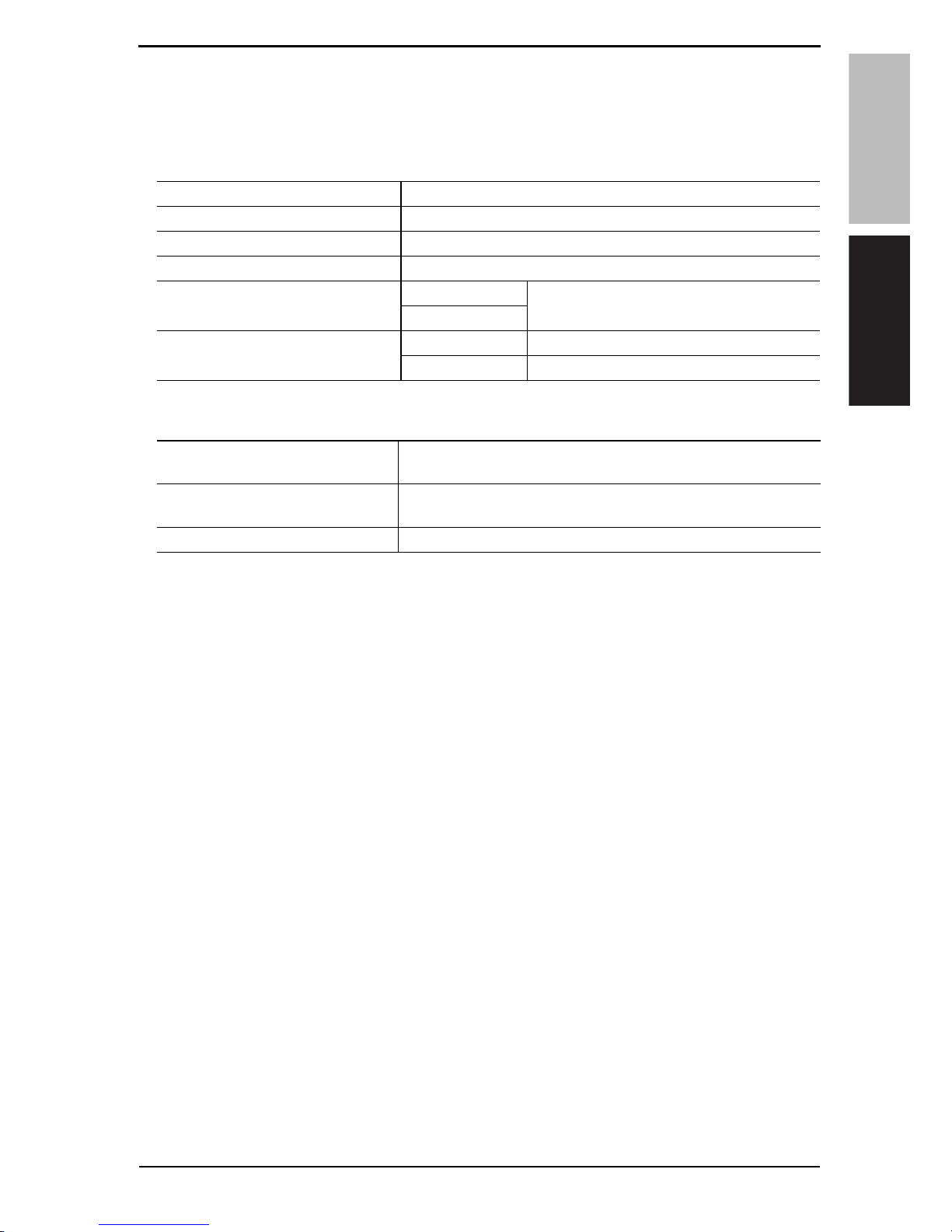
1. Product specification
A. Type
B. Machine specifications
C. Operating environment
• Conforms to the operating environment of the main body.
NOTE
• These specifications are subject to change without notice.
Name Mailbin kit
Installation Install at the top section of the finisher elevator tray.
Number of bins 4 bins
Number of sheets stored per bin 125 sheets (Total 500 sheets) (90 g/m
2
, 24 lb)
Storable paper
Plain paper
60 to 90 g/m
2
(16 to 24 lb)
Recycled paper
Storable paper size
Metric area A5S, B5, A4
Inch area
5-
1
/2 x 8-1/2S, 8-1/2 x 11
Power requirements
DC 24 V (Supplied from the finisher)
DC 5 V (Generated inside the mail bin)
Dimensions
340 mm (W) x 509 mm (D) x 387 mm (H)
13.5 inch (W) x 20 inch (D) x 15.25 inch (H)
Weight 8.0 kg (17.75 lb)
Y108462-99 Service Manual

1. Product specification Field Service Ver. 2.0 Jan. 2008
2
MT-502
General
Blank Page
Service Manual Y108462-9

Field Service Ver. 2.0 Jan. 2008 2. Other
3
MT-502Maintenance
Maintenance
2. Other
2.1 Disassembly/adjustment prohibited items
A. Paint-locked screws
NOTE
• To prevent loose screws, a screw lock in blue or green series color is applied to
the screws.
• The screw lock is applied to the screws that may get loose due to the vibrations
and loads created by the use of machine or due to the vibrations created during
transportation.
• If the screw lock coated screws are loosened or removed, be sure to apply a screw
lock after the screws are tightened.
B. Red-painted screws
NOTE
• The screws which are difficult to be adjusted in the field are painted in red in order
to prevent them from being removed by mistake.
• Do not remove or loosen any of the red-painted screws in the field. It should also
be noted that, when two or more screws are used for a single part, only one representative screw may be marked with the red paint.
C. Variable resistors on board
NOTE
• Do not turn the variable resistors on boards for which no adjusting instructions
are given in Adjustment/Setting.
D. Removal of PWBs
CAUTION
• When removing a circuit board or other electrical component, refer to “Handling of
PWBs” and follow the corresponding removal procedures.
• The removal procedures given in the following omit the removal of connectors and
screws securing the circuit board support or circuit board.
• Where it is absolutely necessary to touch the ICs and other electrical components
on the board, be sure to ground your body.
Y108462-9 Service Manual
 Loading...