

Olivetti d-Color MF 552 plus, d-Color MF 452 plus, d-Color MF 362 plus, d-Color MF 282 plus, d-Color MF 222 plus Installation Manual
Page 1

E-1
INSTALLATION MANUAL
d-Color MF 552 plus/d-Color MF 452 plus/
d-Color MF 362 plus/d-Color MF 282 plus/d-Color MF 222 plus
<Important>
Be sure to correctly follow the procedures in order as explained in this Installation Manual.
If you do not follow the procedure in order, the image trouble may occur.
© Olivetti S.p.A
I. Outline of installation procedures (d-Color MF 552 plus/d-Color MF 452 plus)
When installing the machine and associated options as a system, follow the order shown on the upper.
Caution:
• For the detailed installation procedures for each
option, follow the instructions given in the corresponding installation manual and perform the
procedures correctly. (Optional devices must be
installed after completing the main unit installation.)
• Once the Power Switch is turned ON, do not
turn OFF it until the installation work has been
completed.
• When placing the machine on the floor, make
sure to use the paper feed cabinet to secure the
performance and the quality of the product.
• Lifting the machine in an awkward position or
transporting it in a poorly balanced position
could result in personal injury. When transport-
ing the machine, assign an adequate number of
persons to the job and ensure that each person
can take a good position of not being excessively loaded.
(mass: approx. 101 kg (222-11/16 lb))
AU-102
WT-506
AU-201
*2
SP-501
PC-110
OT-506
Machine
PC-210
MK-730
FS-534FS-533PK-519
MK-734
KH-102
PC-410
TK-101
AU-201
*1
MK-735
HT-509
ZU-606
*4
FS-535
*4
JS-506
LU-204
LU-301
PK-520
SD-511
JS-602
*4
PI-505
*4
PK-521
*4
SD-512
*4
UK-204
*3
Electronic system options
EK-606
*3
EK-607
*3
SC-508
*3
FK-511
VI-506
IC-414
✱ Electronic system options
*1
: When installing the AU-201 with MK-735
*2
: When installing the AU-201 without MK-735
*3
: No particular order in installation procedures.
*4
: Unable to be installed in d-Color MF 452 plus.
UK-208
*3
KP-101
A2XKIXC001DA
Applied Machines: d-Color MF 552 plus/d-Color MF 452 plus/d-Color MF 362 plus/
d-Color MF 282 plus/d-Color MF 222 plus
Y115290-3 Installation ManualY115290-3 Installation Manual
Page 2

E-2
Outline of installation procedures (d-Color MF 362 plus/d-Color MF 282 plus/d-Color MF 222 plus)
When installing the machine and associated options as a system, follow the order shown on the upper.
Caution:
• For the detailed installation procedures for each
option, follow the instructions given in the corresponding installation manual and perform the
procedures correctly . (Optional devices must be
installed after completing the main unit installation.)
• When placing the machine on the floor, make
sure to use the paper feed cabinet to secure the
performance and the quality of the product.
• To use this machine, install the dual scan document feeder, the reverse automatic document
feeder, or the original cover.
Even if you do not install the original cover, be
sure to install the hinge covers supplied with
the original cover.
• Once the Power Switch is turned ON, do not
turn OFF it until the installation work has been
completed.
• Lifting the machine in an awkward position or
transporting it in a poorly balanced position
could result in personal injury. When transporting the machine, assign an adequate number of
persons to the job and ensure that each person
can take a good position of not being excessively loaded.
(mass: approx. 85 kg (187-3/8 lb))
*1
: When installing the AU-201 with MK-735
*2
: When installing the AU-201 without MK-735
*3
: No particular order in installation procedures.
*4
: No installation is required when DF-701 is loaded.
*5
: Unable to be installed in d-Color MF 222 plus.
UK-204
*3
PC-110
JS-506
Machine
PC-210
SP-501 OC-511DF-701
PK-520
SD-511
MK-730
AU-102
FS-534
Electronic system options
FS-533
PK-519
MK-735
EK-606
*3
EK-607
*3
UK-208
*3
SC-508
VI-506
*5
IC-414
*5
PC-410
MK-734
HT-509
WT-506
AU-201
*2
DF-624
AU-201
*1
KH-102
✱ Electronic system options
KP-101
FK-511
UK-209
*4
A161IXC001DA
Installation Manual Y115290-3
Page 3

E-3
II. Installation space (unit: mm (inch))
d-Color MF 552 plus + PC-210 + ZU-606 + FS-535
+ LU-204
d-Color MF 362 plus + DF-701 + PC-210 + FS-534
+ MK-730
III. Pre-installation check items
1. Select a level and stable place for installing the
machine.
2. Be sure to use a power source of the voltage and
frequency indicated in the product specifications.
Ensure that the current carrying capacity of the
power outlet is at least equal to the current listed
in the product specifications.
3. Power the machine directly from a dedicated
power outlet. (Do not use an extension cord.)
4. Do not plug or unplug the power cord with wet or
dirty hands, otherwise you may get an electric
shock.
5. Avoid a hot and humid environment, or a place
exposed to direct sunlight.
6. Avoid a dusty location, or a place near volatile
and flammable substances.
7. Avoid a poorly ventilated place.
IV. Notes on using touch panel
Be sure to instruct users on the following points.
• This machine uses a capacitive touch panel.
When you touch the touch panel, use your finger or the stylus pen supplied with the machine.
If you touch the panel using your nail or a pen
tip instead of using your finger or the stylus pen,
the touch panel does not respond normally.
• Pressing the touch panel hard may cause dam-
age.
• Do not strongly press the panel or press it using
the sharp tip of mechanical penci ls.
• The key is a finger tapping (quick light touch
using a finger) operation.
A5AYIXC001DA
1217
(47-15/16)
480
(18-7/8)
2763
(108-3/4)
1066
(41-15/16)
1246
(49-1/16)
428
(16-7/8)
818
(32-3/16)
1568
(61-3/4)
386
(15-3/16)
936
(36-7/8)
246
(9-11/16)
A5C1IXC011DA
937
(36-7/8)
225
(8-7/8)
1822
(71-3/4)
660
(26)
1246
(49-1/16)
428
(16-7/8)
818
(32-3/16)
1568
(61-3/4)
386
(15-3/16)
936
(36-7/8)
246
(9-11/16)
Y115290-3 Installation Manual
Page 4

E-4
V. Accessory parts
*1d-Color MF 552 plus/d-Color MF 452 plus: One
d-Color MF 362 plus/d-Color MF 282 plus/d-Color
MF 222 plus: Two
*2
d-Color MF 362 plus/d-Color MF 282 plus/d-Color
MF 222 plus only
*3
d-Color MF 552 plus/d-Color MF 452 plus only
Note:
The parts shown below are used when installing
options. Keep them safe.
• Paper size label: Large capacity unit (LU-301)
(d-Color MF 552 plus/d-Color MF 452 plus only)
• Label (Super G3 label): Fax kit
Note:
This manual provides the illustrations of the accessory
parts and machine that may be slightly different in
shape from yours. In that case, instead of the illustrations, use the appearance of your machine to follow
the installation procedure. This does not cause any
significant change or problem with the procedure.
No. Name Q’ty
1. User’s guide holder 1
2. Installation manual 1 set
3. Paper size label 1
4. Label (Legal restrictions on copying) 1
5. Label (Super G3 label) 1
6. Cap A (Black) 2
7. Cap B (White) 2
8. Power cord 1
9. Power cord instructio n 1
10.
Cord clamp
*1
1 or 2
11. Connector cover 1
12.
Screw A
*2
1
13. Screw B
1
14. Screw C
1
15.
Chart
*3
1
16. Spacer 1
17. Stylus pen 1
18. Waste toner box 1
9738
9646
A161IXC061DA
After unpacking, be sure to get rid of the
packaging materials and keep them out of
the reach of children.
Putting the head in the plastic bag
involves danger of suffocation.
Installation Manual Y115290-3
Page 5

E-5
VI. Removing the machine
1. Unpack and remove the machine package.
2. Remove the machine, holding it by the locations
on the left side and the handles on the right side
as shown in the illustration and keeping it level.
Caution:
Machine mass
d-Color MF 552 plus/d-Color MF 452 plus: approx.
101 kg/222-11/16 lb
d-Color MF 362 plus/d-Color MF 282 plus/d-Color
MF 222 plus: approx. 85 kg/187-3/8 lb
• Make available collective manpower of an
appropriate size for transporting the machine.
• Before attaching the machine to the paper feed
cabinet, make sure that the supplied connector
cover is not attached.
• When attaching the machine, as the reference
fit the machine with the corner A and B of the
paper feed cabinet.
VII. Removing protective tape, packing
and other shipping materials
1. Remove the protective tape and the protective
materials.
Note:
After removing protective tape A, be sure to push
the area indicated by the “ ” mark to lock the
guide. (d-Color MF 552 plus/d-Color MF 452 plus
only)
When holding the transportation handles,
be careful not to catch your fingers in the
machine.
A2XKIXC003DA
A2XKIXE034DA
A
B
Connector cover
A5AYIXC003DA
A5AYIXC002DA
<d-Color MF 552 plus/d-Color MF 452 plus>
A
Y115290-3 Installation Manual
Page 6

E-6
2. Open the right door and remove the protective
sheet and packaging materials.
Note:
After removing the packaging materials, make
sure that the transfer roller assy is secured in
place. In the case of <NG>, press the transfer
roller assy into place so that it is secured as shown
in <OK>.
3. Remove the locking screws.
4. Remove the protective sheets.
A5C1IXC001DA
A5C1IXC003DA
A5C1IXC002DA
B
A5C1IXE012DA
<d-Color MF 362 plus/d-Color MF 282 plus/
d-Color MF 222 plus>
<Viewed from point B>
A161IXC005DB
< OK > < NG >
A2XKIXC008DA
A2XKIXC009DA
Installation Manual Y115290-3
Page 7

E-7
5. Slide out the tray 1 and remove the protective
tape from the inside of the tray.
6. Slide out the tray 2 and remove the tray locking
materials.
7. Remove the protective tapes from the inside of
the tray 2 and remove accessory parts.
8. <d-Color MF 552 plus/d-Color MF 452 plus>
Open the lower front door.
<d-Color MF 362 plus/d-Color MF 282 plus/dColor MF 222 plus>
Open the front door.
A5C1IXC005DA
A161IXC009DA
A5AYIXC004DA
A2XKIXC010DA
A161IXC015DB
Y115290-3 Installation Manual
Page 8

E-8
9. <d-Color MF 552 plus/d-Color MF 452 plus>
Remove the protective tape.
<d-Color MF 362 plus/d-Color MF 282 plus/dColor MF 222 plus>
Remove the protective tape and protective material.
10. Remove the protective tape from the drum units
and developing units.
Note:
Do not remove the tape A in this procedure.
11. Remove the protective materials from the four
places.
Note:
Keep the protective materials. It is necessary for
transporting the machine.
12. Release the lever of the drum unit (K).
13. Slightly slide the drum unit (K) out and remove
the protective tape
A2XKIXC011DA
Protective tape
A161IXC010DC
Protective tape
Protective material
A5AYIXC005DA
A
A2XKIXC013DA
A2XKIXC014DA
A2XKIXC015DA
Installation Manual Y115290-3
Page 9

E-9
14. Slide the drum unit (K) into the machine.
15. Lock the drum unit (K) with the lever.
16. Install the supplied waste toner box.
Note:
Push the areas indicated by the “ ” marks to set
the waste toner box to the machine
* Perform the following steps 17 to 19 only when
installing d-Color MF 552 plus/d-Color MF 452
plus.
17. Close the lower front door.
18. Open the upper front door.
19. Remove the protective tape and protective
material.
VIII. Installing the toner cartridge
Note:
Since cartridge is not supplied with the machine,
purchase toner cartridge (of different color s ) separately.
1. Shake the toner cartridge up and down and left to
right 5 to 10 times respectively.
Note:
Shake the cartridge adequately. Otherwise, it may
cause trouble.
2. Insert the toner cartridge into the machine.
Note:
• Make sure that the color is same between
inserting port and the toner cartridge.
• Make sure that the blue label position of the
toner cartridge is matched with the one of the
machine side.
A2XKIXC016DA
A2XKIXC031DA
Protective tape/
Protective material
A0EDIXC020DA
A2XKIXC017DA
Y115290-3 Installation Manual
Page 10

E-10
3. Push the toner cartridge all the way in and rotate
it clockwise to lock it.
Note:
Make sure that the toner cartridge is pushed all the
way in.
4. Using the same procedure, install the toner cartridges for other colors of toner.
5. <d-Color MF 552 plus/d-Color MF 452 plus>
Close the upper front door.
<d-Color MF 362 plus/d-Color MF 282 plus/dColor MF 222 plus>
Close the front door.
IX. Mounting the accessory parts
1. Attach the supplied caps A and B.
2. Remove the pr otec ti ve cove r from the sup pli ed
stylus pen.
Note:
Discard the removed protective cover.
3. Set the stylus pen in the place shown in the illustration.
4. Attach the supplied cord clamp to the scanner
rear cover of the machine. (One supplied screw
A)
Note:
Only d-Color MF 362 plus/d-Color MF 282 plus/dColor MF 222 plus needs this step.
5. Attach the supplied connector cover to the
machine. (One supplied screw B)
A2XKIXC018DA
A2XKIXC019DA
A2X0IXC068DA
A5C1IXC007DA
A161IXE047DA
A161IXE065DA
Installation Manual Y115290-3
Page 11
E-11
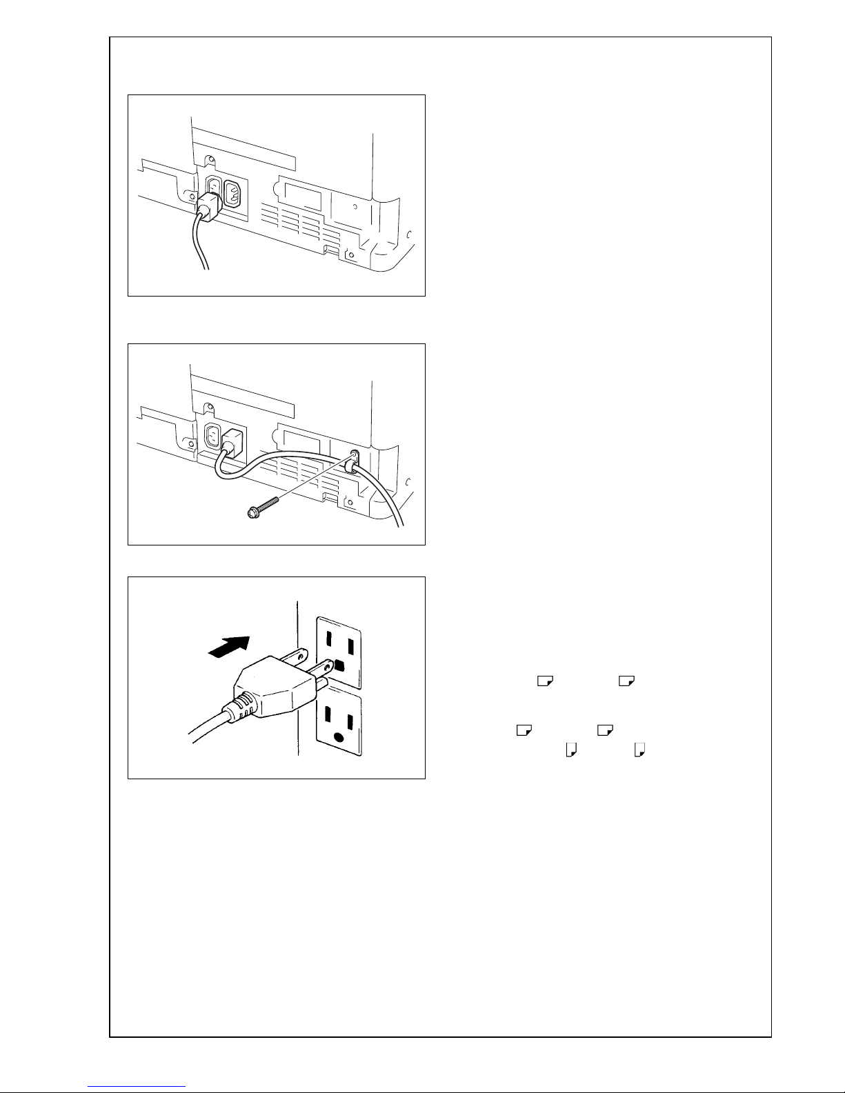
X. Connecting the power cord
1. Connect the power cord.
2. Fit the supplied cord clamp over the power cord.
(One supplied screw C)
3. Plug the power cord into the power outlet.
XI. Toner supply
Turn ON the Main Power Switch.
Note:
• Toner is automatically supplied in parallel with
warm-up.
• If any one of the toner cartridges is not set,
toner supply does not start.
XII. Adjusting touch panel
1. Press the Menu key.
2. Touch “Accessibility.”
3. Touch “Touch Panel Adjustment.”
4. Using the stylus pen, lightly touch the center of
the + markers at four places on the touch panel.
(Any specific marker can be the first one.)
Note:
Pressing the touch panel hard may cause damage.
* When all the markers at four places have been
touched, the start key turns blue and lights up
steadily blue.
5. Press the start key.
6. Touch “Close.”
XIII.Date/Time setting (Administrator settings)
1. Select the Date/Time Setting function as follows:
Menu → Utility → Administrator Settings → Enter
the Administrator Password (Default setting:
1234567812345678) → System Settings → Date/
Time Settings.
2. Select the item you want to set and press the
clear key.
3. Enter the data for the year, month, day, and timeof-day from the 10-key pad.
Note:
Switch between “Bookmark” and “Display Keypad”
on the left side of the touch panel as necessary.
4. Touch “OK.”
5. Touch “Close” three times.
XIV. Setting gradation adjustment
1. Set that A3 or Ledger paper is loaded in
the tray.
Note:
If the A3 or Ledger paper is not readily
available, use A4 or Letter paper.
2. Display the Service Mode screen.
(For details of how to display the Service Mode
screen, see the service manual.)
3. Touch “Imaging Process Adjustment.”
4. Touch “Gradation Adjust.”
5. Check that “Stabilizer” is selected and press the
start key.
* When the start key lights up blue, go to step 6.
Note:
When a maintenance call occurs, see the service
manual.
A161IXE042DA
A161IXE043DB
C4004U139CA
Y115290-3 Installation Manual
Page 12

E-12
<If A3 or Ledger paper is set in step 1>
6. Touch “Printer”, select “A3 /11
x 17 ”, and
press the start key.
A test pattern will then be produced on the A3
or Ledger paper.
7. Place the test pattern face down on the original
glass.
8. Place about ten sheets of A3 or Ledger
paper on the test pattern placed on the original
glass.
Lower the cover.
9. Press the start key.
The machine will start reading the test pattern.
10. When the machine completes reading the test
pattern, the “Gradation Adjust” screen will reappear.
11. Touch “Copy”, select “A3 /11
x 17 ”, and
press the start key.
A test pattern will then be produced on the
A3 or Ledger paper.
12. Place the test pattern face down on the original
glass.
13. Place about ten sheets of A3 or Ledger
paper on the test pattern placed on the original
glass.
Lower the cover.
14. Press the start key.
The machine will start reading the test pattern.
15. When the machine completes reading the test
pattern, the “Gradation Adjust” screen will reappear.
16. Touch “END.”
A161IXC021DA
Magenta
A161IXC022DA
A161IXC023DA
Cyan
A161IXC022DA
Installation Manual Y115290-3
Page 13

E-13
<If A4 or Letter paper is set in step 1>
6. Touch “Printer”, select “A4 /8
½ x 11 ”, and
press the start key.
A test pattern will then be produced on the two
A4 or Letter papers.
7. Place the test pattern face down on the original
glass.
8. Place about ten sheets of A3 or Ledger
paper on the test pattern placed on the original
glass.
Lower the cover.
9. Press the start key.
The machine will start reading the test pattern.
10. When the machine completes reading the test
pattern, the “Gradation Adjust” screen will reappear.
11. Touch “Copy”, select “A4 /8
½ x 11 ”, and
press the start key.
A test pattern will then be produced on the two
A4 or Letter papers.
12. Place the test pattern face down on the original
glass.
13. Place about ten sheets of A3 or Ledger
paper on the test pattern placed on the original
glass.
Lower the cover.
14. Press the start key.
The machine will start reading the test pattern.
15. When the machine completes reading the test
pattern, the “Gradation Adjust” screen will reappear.
16. Touch “END.”
A161IXC024DA
Magenta
A161IXC022DA
A161IXC025DA
Cyan
A161IXC022DA
Y115290-3 Installation Manual
Page 14
E-14
XV. Date/Time setting (Service Mode)
1. Make sure that the Service Mode screen is displayed.
2. Displa y the Date & Time Setting screen.
(T o display the Date & Time Setting screen, press
Stop → 1 → 1 → 4 → 4 → Clear on the control
panel.)
3. Press the clear key.
4. Enter the data for the year, month, day, and timeof-day from the 10-key pad on the touch panel.
5. Touch “Entry.”
Note:
Touching the Entry key returns the figures in the
Date & Time Setting screen to 0 and Date & Time
Setting has been completed.
6. Touch “END.”
XVI. Install date
1. Select the Install Date function as follows:
System 1 → Install Date.
2. Press the clear key.
3. Enter the data for the year, month, and day from
the 10-key pad on the touch panel.
4. Touch “Entry.”
Note:
Touching the Entry key returns the figures in the
Install Date screen to 0 and Install Date has been
completed.
5. Touch “END.”
XVII. Serial number input
Note:
Serial number input is needed only for optional
devices that will be installed later.
1. Select the Serial Number Input function as follows: System 1 → Serial Number.
2. Touch the item you want to enter and input the
serial number.
3. Touch “END.”
4. For other devices, enter their serial number in the
same way.
5. Touch “END.”
XVIII. Unit change
Note:
This function allows the user to select the type of
message that will appear when the replacement
time arrives for each of the different units.
1. Select the Uni t Change function as fol low s:
System 2 → Unit Change.
2. Select the appropriate message type for each
unit.
3. Touch “END.”
XIX. List output
1. Load the tray 1 with A4 or Letter paper.
2. Touch “List Output.”
3. Check that “Machine Management List” is
selected and press the start key.
The list will be output.
4. Output “Adjustments List” in the same way.
5. Touch “2.”
6. Check that “Service Parameter” is selected and
press the start key.
The list will be output.
7. Touch “END.”
8. Touch “Exit” on the Service Mode screen.
9. Turn OFF and ON the Main Power Switch.
Note:
When displayed the Service Mode screen, be sure
to turn off the main power after exiting the Service
Mode screen and wait for 10 seconds or more
before turning on.
Installation Manual Y115290-3
Page 15

E-15
XX. Adjusting the height
Note:
• The following “XX. Adjusting the height” to
“XXV. Adjusting the document stop position”
and “XXVII. Changing the stopper position”
shall be referenced only when installing d-Color
MF 552 plus/d-Color MF 452 plus.
• When installing the dual scan document feeder
DF-701 or reverse automatic document feeder
DF-624 to d-Color MF 362 plus/d-Color MF 282
plus/d-Color MF 222 plus, adjustments shall be
made according to the installation manual of
each option.
1. Check the clearance between the upper face of
scanner and the protrusion on the dual scan document feeder side. (Three spots)
* There must be no clearance between the protru-
sion on the dual scan document feeder and the
upper face of scanner.
2. If there is any clearance, adjust the height by
turning the adjustment screw on the right side
viewed from the back.
Clockwise: The rear side will move up.
Counterclockwise: The rear side will move down.
• If further adjustment is required, adjust the height
by using the adjustment screw on the left side
viewed from the back together.
Clockwise: The rear side will move up.
Counterclockwise: The rear side will move down.
XXI. Adjusting skew feed (Front side)
Note:
Perform this adjustment if necessary.
1. Close the dual scan document feeder.
2. Check how the edges of the chart are misaligned.
The amount of the deviation of the chart will be X.
A3CFIXC010DA
A3CEIXC003DB
Protrusion
Protrusion
OK
NG
Protrusion
A2XKIXE027DA
9J07IXC043DA
XX
Deviation in + (plus) Deviation in - (minus)
Y115290-3 Installation Manual
Page 16

E-16
3. Place the chart in the document feeding tray (with
the side having an arrow facing up).
4. Make copies 5 times repeatedly in single side
mode.
5. Fold all 5 sample copies as illustrated and check
for any deviation.
Deviation on the sample will be Y.
6. Obtain the difference between the deviation of
the chart and the deviation of the sample.
Difference of the deviation = Y - X
Specifications: 0 ± 2 mm
* If the difference of the deviation does not fall
within the specified range, perform the following
adjustment.
7. Loosen the mounting screw on the right hinge
viewed from the front.
8. When the difference of the deviation is + (plus),
turn the adjustment screw located at the back of
the dual scan document feeder clockwise to
adjust.
Note:
• Look at the guide lines when making the adjust-
ment.
• When turning the screw, be sure not to raise the
dual scan document feeder until in an upright
position.
* To prevent the adjustment screw breakage, be
sure to follow the above instructions.
A3CFIXC013DA
9J07IXC043DA
YY
Deviation in + (plus) Deviation in - (minus)
A3CEIXC004DA
Mounting screw
A2XKIXC026DB
Guide lines
Installation Manual Y115290-3
Page 17

E-17
9. When the difference of the deviation is - (minus),
turn the adjustment screw located at the back of
the dual scan document feeder counterclockwise
to adjust.
Note:
• Look at the guide lines when making the adjust-
ment.
• When turning the screw, be sure not to raise the
dual scan document feeder until in an upright
position.
* To prevent the adjustment screw breakage, be
sure to follow the above instructions.
10. Tighten the mounting screw on the right hinge
that has been loosened in step 7 using a screwdriver.
XXII. Adjusting leading edge skew
(Back side)
Note:
Perform this adjustment if necessary.
1. Place the chart in the document feeding tray
(Make sure that the blank surface of the chart
faces up).
2. Make copies 5 times repeatedly in duplex mode.
3. Fold all 5 sample copies as illustrated and check
for any deviation.
Deviation on the sample will be Z.
4. Obtain the difference between the deviation of
the chart and the deviation of the sample.
Difference of the deviation = Z - X
Specifications: 0 ± 2 mm
* If the difference of the deviation does not fall
within the specified range, perform the following
adjustment.
5. Open the dual scan document feeder and remove
the two screws shown in the illustration.
6. Close the dual scan document feeder.
7. Remove the front cover.
A2XKIXC025DB
Guide lines
A3CEIXC039DA
9J07IXC043DA
ZZ
Deviation in + (plus) Deviation in - (minus)
A3CEIXC032DA
A3CEIXC033DA
Y115290-3 Installation Manual
Page 18

E-18
8. Loosen the two screws shown in the illustration.
9. Turn the adjustment dial according to the difference of the deviation.
When the difference is a positive (+) value, turn
the dial clockwise
When the difference is a negative (-) value, turn
the dial counterclockwise
10. Make duplex copies and check the amount of
deviation (Z).
11. After completing the adjustment, tighten the
screws loosened in step 8.
12. Install the front cover removed in step 7. (Two
screws)
XXIII. Magnification adjustment
<Magnification in the feeding direction>
Note:
Perform this adjustment if necessary.
1. Place the chart in the document feeding tray
(with the side having an arrow facing up).
2. Make full size copies.
3. Check whether the difference in the width C
between the chart and the copy sample is within
the specified range.
Difference in the width C = C of the copy sample
– C of the chart
Specifications: 0 ± 1.0 mm
* If the difference in the width C does not fall within
the specified range, perform the following
adjustment.
4. Display the Service Mode screen.
(For details of how to display the Service Mode
screen, see the service manual.)
5. Touch “ADF.”
6. Touch “FD-Mag. Adj.(F).”
7. Check that “Orig. Feed Zoom Ad” is selected.
8. Specify a value using the -/+ key.
Adjustable range: -2.00 % to +2.00 %
(0.1% per step)
If the difference in the width C is greater than the
specifications, use the – (minus) key.
If the difference in the width C is smaller than the
specifications, use the + (plus) key.
A3CEIXC034DA
A3CEIXC035DA
A3CFIXC013DA
A1DMIXC018DA
Installation Manual Y115290-3
Page 19

E-19
9. Touch “END.”
10. Touch “Exit” on the Service Mode screen.
11. Turn OFF and ON the Main Power Switch.
Note:
When displayed the Service Mode screen, be sure
to turn off the main power after exiting the Service
Mode screen and wait for 10 seconds or more
before turning on.
12. Make copies again and check the difference in
the width C.
<Back side magnification in the feeding direction>
Note:
Perform this adjustment if necessary.
13. Place the chart in the document feeding tray.
(Make sure that the blank surface of the chart
faces up.)
14. Make full size copies.
* Make copies in duplex mode.
15. Check whether the difference in the width C
between the chart and the copy sample is within
the specified range.
Difference in the width C = C of the copy sample
– C of the chart
Specifications: 0 ± 1.0 mm
* If the difference in the width C does not fall within
the specified range, perform the following
adjustment.
16. Display the Service Mode screen.
(For details of how to display the Service Mode
screen, see the service manual.)
17. Touch “ADF.”
18. Touch “FD-Mag. Adj.(B).”
19. Check that “Orig. Feed Zoom Ad” is selected.
20. Specify a value using the -/+ key.
Adjustable range: -2.00 % to +2.00 %
(0.1% per step)
If the difference in the width C is greater than the
specifications, use the – (minus) key.
If the difference in the width C is smaller than the
specifications, use the + (plus) key.
21. Touch “END.”
22. Touch “Exit” on the Service Mode screen.
23. Turn OFF and ON the Main Power Switch.
Note:
When displayed the Service Mode screen, be sure
to turn off the main power after exiting the Service
Mode screen and wait for 10 seconds or more
before turning on.
24. Make copies again and check the difference in
the width C.
<Back side zoom in the main scanning direc ti on>
Note:
Perform this adjustment if necessary.
25. Place the chart in the document feeding tray.
(Make sure that the blank surface of the chart
faces up.)
26. Make full size copies.
* Make copies in duplex mode.
A3CEIXC039DA
A1DMIXC018DA
A3CEIXC039DA
Y115290-3 Installation Manual
Page 20

E-20
27. Check whether the difference in the width D
between the chart and the copy sample is within
the specified range.
Difference in the width D = D of the copy sample
– D of the chart
Specifications: 0 ± 2.0 mm
* If the difference in the width D does not fall within
the specified range, perform the following
adjustment.
28. Display the Service Mode screen.
(For details of how to display the Service Mode
screen, see the service manual.)
29. Touch “ADF.”
30. Touch “Main Scanning Direction Zoom.”
31. Check that “Main scanning direction zoom adj.”
is selected.
32. Specify a value using the -/+ key.
Adjustable range: -1.00 % to +1.00 %
(0.1% per step)
If the difference in the width D is greater than the
specifications, use the – (minus) key.
If the difference in the width D is smaller than the
specifications, use the + (plus) key.
33. Touch “END.”
34. Touch “Exit” on the Service Mode screen.
35. Turn OFF and ON the Main Power Switch.
Note:
When displayed the Service Mode screen, be sure
to turn off the main power after exiting the Service
Mode screen and wait for 10 seconds or more
before turning on.
36. Make copies again and check the difference in
the width D.
XXIV. Mixed original size adjustment
Note:
Perform this adjustment if necessary.
1. Display the Service Mode screen.
(For details of how to display the Service Mode
screen, see the service manual.)
2. Touch “ADF.”
3. Touch “Mixed original size adjustment.”
4. Place the chart in the document feeding tray
(lengthwise).
5. Press the Start key.
6. Check that “Adjustment Result” is “OK.”
7. Touch “END.”
XXV. Adjusting the document stop position
<Sub Scanning Direction 1-side/ Sub Scanning
Direction 2-side>
Note:
Perform this adjustment if necessary.
1. Place the chart in the document feeding tray (with
the side having an arrow facing up).
2. Make full size copies.
A1DMIXC015DA
A3CFIXC028DA
A3CFIXC013DA
Installation Manual Y115290-3Installation Manual Y115290-3
Page 21

E-21
3. Place the chart in the document feeding tray.
(Make sure that the blank surface of the chart
faces up.)
4. Make full size copies.
* Make copies in duplex mode.
5. Check whether the difference in the width B
between the chart and the copy sample is within
the specified range.
Difference in the width B = B of the copy sample –
B of the chart
Specifications: 0 ± 2.0 mm
* If the difference in the width B does not fall within
the specified range, perform the following
adjustment.
6. Display the Service Mode screen.
(For details of how to display the Service Mode
screen, see the service manual.)
7. Touch “ADF.”
8. Touch “Original Stop Position.”
9. Touch “Sub Scanning Direction 1-Side” or “Sub
Scanning Direction 2-Side.”
10. While looking at the copy sample, enter a value
using the ten-key pad. (To switch the signs,
press the +/- key.)
Adjustable range: -4.0 mm to +4.0 mm
(0.1 mm per step)
If the difference in the width B is greater than the
specifications, enter a positive (+) value.
If the difference in the width B is smaller than the
specifications, enter a negative (-) value.
11. Touch “END.”
12. Touch “Exit” on the Service Mode screen.
13. Turn OFF and ON the Main Power Switch.
Note:
When displayed the Service Mode screen, be sure
to turn off the main power after exiting the Service
Mode screen and wait for 10 seconds or more
before turning on.
14. Make copies again and check the difference in
the width B.
<Main Scanning (Front)/ Main Scanning (Back)>
Note:
Perform this adjustment if necessary.
15. Place the chart in the document feeding tray
(with the side having an arrow facing up).
16. Make full size copies.
17. Place the chart in the document feeding tray.
(Make sure that the blank surface of the chart
faces up.)
18. Make full size copies.
* Make copies in duplex mode.
A3CEIXC039DA
A1DMIXC017DA
A3CFIXC013DA
A3CEIXC039DA
Y115290-3 Installation Manual
Page 22

E-22
19. Check whether the difference in the width A
between the chart and the copy sample is within
the specified range.
Differen ce i n th e w i dth A = A of the co p y sa m pl e
– A of the chart
Specifications: 0 ± 2.0 mm
* If the difference in the width A does not fall within
the specified range, perform the following
adjustment.
20. Display the Service Mode screen.
(For details of how to display the Service Mode
screen, see the service manual.)
21. Touch “ADF.”
22. Touch “Original Stop Position.”
23. Touch “Main Scanning (Front)” or “Main Scanning (Back).”
24. While looking at the copy sample, enter a value
using the ten-key pad. (To switch the signs,
press the +/- key.)
Adjustable range: -4.4 mm to +4.4 mm
(0.1 mm per step)
If the difference in the width A is greater than the
specifications, enter a positive (+) value.
If the difference in the width A is smaller than the
specifications, enter a negative (-) value.
25. Touch “END.”
26. Touch “Exit” on the Service Mode screen.
27. Turn OFF and ON the Main Power Switch.
Note:
When displayed the Service Mode screen, be sure
to turn off the main power after exiting the Service
Mode screen and wait for 10 seconds or more
before turning on.
28. Make copies again and check the difference in
the width A.
XXVI. Affixing the label (Legal restrictions
on copying)
Affix the label (Legal restrictions on copying) to the
position shown below.
XXVII. Changing the stopper position
1. Raise the two hinge covers on the back of the
dual scan document feeder and remove the stopper from the hinge of the dual scan document
feeder.
2. Change the set position of the stopper to the
upper side and secure it in position.
Note:
When the dual scan document feeder/reverse
automatic document feeder is adjusted in service mode, “Adjustments list” should be output
again as necessary. (Refer to E-14 “XIX. List
output.”)
A1DMIXC019DAA1DMIXC016DA
<Front> <Back>
A2XKIXE030DA
Label
A3CEIXE047DA
Stopper
Installation Manual Y115290-3
Page 23

E-23
XXVIII. Affixing the paper size label
Affix the paper size labels that correspond to the
sizes of paper used in each tray.
For loading the paper as well as setting the paper
type, refer to the user’s guide.
XXIX. Check through test print
Make operation checks using “Setting Information
Print.”
1. Select the function to be used as follows:
Menu → Utility → User Settings → Printer Set-
tings → Print Reports.
The types of the test prints that can be printed will
be displayed.
2. Touch “Configuration Page.”
3. Touch A4 size and press the start key.
Check that the machine produces the corresponding printed page.
4. Touch “Cancel” and then touch “Close” four
times.
XXX. Connecting the network cable
1. Connect the networking equipment (HUB) using
the network cable.
Note:
The following shows the recommended network
cables that correspond to each communication
speed.
• 10BaseT/100BaseTX: Category 5
• 1000BaseT: Category 5E, Category 6
2. Check LEDs for lighting conditions.
LED1:
Should light up steadily if the link network connection has been made.
LED2:
Should blink according to the communications
status of the ACT network.
<When adding no paper feed options>
3. Remove the indicated knockout from the
machine’s interface cover using nippers.
A161IXC026DA
Paper size label
A5C1IXC008DB
Networkport
LED1
LED2
A161IXC027DB
Y115290-3 Installation Manual
Page 24

E-24
4. Route the network cable through the harness
guides and pass it through the notch cut in step 3.
Note:
Leave an appropriate amount of slack in the portion of the cable between the plug and the top harness guide in a manner which does not interfere
with the opening and closing of the cover.
<When using the paper feed cabinet PC-110/PC-210/PC410>
3. Remove the rear right cover from the paper feed
cabinet. (Two screws)
4. Remove the knockout from the rear right cover
removed in step 3 using nippers.
5. Route the network cable through the harness
guides and three wire saddles.
Note:
Leave an appropriate amount of slack in the portion of the cable between the plug and the top harness guide in a manner which does not interfere
with the opening and closing of the cover.
6. Route the cable through the notch cut in step 4
and attach the rear right cover. (Two screws)
A5C1IXC009DB
Leave an appropriate amount of slack.
A161IXC056DA
A161IXC057DA
A5C1IXC010DB
Leave an appropriate amount of slack.
A161IXC058DA
Installation Manual Y115290-3
Page 25

E-25
XXXI. Performing Non-Image Area Erase
Check
Note:
Perform the below at the site where customer
uses the machine.
1. Display the Service Mode screen.
(For details of how to display the Service Mode
screen, see the service manual.)
2. Select the Non-Image Area Erase Check function
as follows:
Machine → Non-Image Area Erase Check.
Note:
• <d-Color MF 552 plus/d-Color MF 452 plus>
Open fully the dual scan document feeder.
<d-Color MF 362 plus/d-Color MF 282 plus/dColor MF 222 plus>
Open fully original options if loaded.
• Do NOT place a document on the document
glass.
• Clean the document glass if dirty.
3. Press the Start key.
4. Make sure that “Result” is “OK.”
Note:
If “Result” is “NG1” or “NG2”, review the place and
direction of installation, or take measures to block
the light source (by covering it, etc.), then perform
installation checking again.
(If a fluorescent light or other bright light sources
exist right above the machine, the light source can
hinder installation checking and cause operation
errors in the Non-Image Area Erase Check. For
detailed information, see the service manual.)
5. Touch “OK.”
6. Touch “Exit” on the Service Mode screen.
7. Turn OFF and ON the Main Power Switch.
Note:
When displayed the Service Mode screen, be sure
to turn off the main power after exiting the Service
Mode screen and wait for 10 seconds or more
before turning on.
XXXII. Network setting
Make the TCP/IP address setting for the network.
Note:
Consult the network administrator for the setting
value to be entered and make settings as
required.
1. Select the function to be used as follows:
Menu → Utility → Administrator Settings → Enter
the Administrator Password → Network Settings
→ TCP/IP Settings → IPv4 Settings.
2. Touch “Manual Input” of IP Address Setting
Method and make the following settings.
IP Address: IP address of the controller
Subnet Mask: Subnet mask of the network, to
which the machine is connected
Default Gateway: IP address of the default gateway
3. Touch “OK.”
4. Turn OFF and ON the Main Power Switch.
5. Select the function to be used as follows:
Menu → Utility → Administrator Setting → Enter
the Administrator Password → Network Settings
→ Forward → Detail Settings → PING Confirmation, and make the operation check of TCP/IP.
A161IXC020DA
Note:
After completing all the steps, take a sample
copy in color mode, and confirm the image. If
image troubles occur, first turn OFF and ON the
Main Power Switch, and then redo the steps
from E-11 “XII. Adjusting touch panel” to E-14
“XIX. List output.”
Y115290-3 Installation Manual
Page 26

E-26
XXXIII. Adjusting registration of paper
source options
Note:
Performing this procedure is necessary only when
the paper feed cabinet PC-110/PC-210/PC-410 is
installed.
1. Displa y the Ser v ice Mode screen.
(For details of how to display the Service Mode
screen, see the service manual.)
2. Select the function to be used as follows:
Machine → Printer Area → Pr in ter Image Cent er ing Side 1 → 3rd.
3. Press the start key.
A test print will be produced.
4. Measure width A of the test pattern on the backside of the test print produced and check that it
falls within the specified ran ge.
Specifications: 3.0 mm ± 1.0 mm
5. If the measured width A falls outside the specified
range, see the installation manual of each paper
feed cabinet and make adjustments.
6. Produce another test print and check to see if
width A falls within the specified range.
7. Select the function to be used as follows:
Prt. Image Center. Side 2 (Dup) → 3rd.
8. Press the start key.
A test print will be produced.
9. Measure width A of the test pattern on the backside of the test print produced and check that it
falls within the specified ran ge.
Specifications: 3.0 mm ± 2.0 mm
10. If the measured width A falls outside the specified range, enter the correction value using the
or key.
* When the tray 4 is available with the optional
paper feed cabinet, check the tray and make
adjustments in the same way.
11. Produce another test print and check to see if
width A falls within the specified range.
12. Touch “END.”
13. Touch “Exit” on the Service Mode screen.
14. Turn OFF and ON the Main Power Switch.
Note:
When displayed the Service Mode screen, be sure
to turn off the main power after exiting the Service
Mode screen and wait for 10 seconds or more
before turning on.
XXXIV. Installing the user’s guide holder/
spacer
Install the user’s guide holder and the spacer.
4061IXC152DA
A
Paper exit
direction
4061IXC152DA
A
Paper exit
direction
A2XKIXC020DA
Installation Manual Y115290-3
Page 27

E-27
XXXV. Affixing the panel sheet
Affix the supplied panel sheet to the surface of the
operation panel.
Note:
• The panel sheet is affixed on customer request.
• The panel sheet must be kept by the customer.
XXXVI. Installing the output tray (OT-506)
(d-Color MF 552 plus/d-Color MF 452 plus
only)
1. Open the upper and lower front door of the
machine.
2. Remove the upper left cover from the machine.
(Three screws)
3. Attach the guide supplied with the output tray to
the machine.
4. Install the output tray.
5. Reattach the upper left cover removed in step 27
to the machine. (Three screws)
6. Close the upper and lower front door of the
machine.
A161IXC050DA
A2XKIXC021DA
A2XKIXC032DA
➀
➁
A2XKIXC022DA
Y115290-3 Installation Manual
Page 28

E-28
SP-501 Stamp Unit
INSTALLATION MANUAL
I. Accessory parts
II. Installation procedures
1. Turn off the machine and unplug the power cord
from the power outlet.
2. Raise the dual scan document feeder.
3. To detach the left side of the document pad from
the feeder, separate the two faces of the hookand-loop fastener (at two places on the left).
Note:
When removing the document pad, pull apart the
hook and loop fastener one by one. Pulling the
mall at once may damage the sponge.
4. Remove the cover shown in the illustration.
(Two screws)
5. Remove the ground terminal. (One screw)
6. Remove the connector fastened to the guide
plate.
7. Remove the guide plate. (One screw)
No. Name Shape Q’ty
1. Stamp unit
1
2. Stamp
1
3. Installation
manual
1 set
After unpacking, be sure to get rid of the
packaging materials and keep them out of
the reach of children.
Putting the head in the plastic bag
involves danger of suffocation.
4614U001AA
4614U002AA
4980IXC019DA
A3CEIXC024DA
A3CEIXC025DA
A3CEIXC026DA
A3CEIXC027DA
Applied Machines: d-Color MF 552 plus/d-Color MF 452 plus
COLOR MFP: 55 ppm/45 ppm
Product Code: A5AY/A5C0
Installation Manual Y115290-3
Page 29

E-29
8. Remove the ground terminal. (One screw)
9. Mount the supplied stamp in stamp unit.
Note:
Align the round pin of the stamp with the slit in the
stamp unit side.
10. Route the harness through the hole shown in the
illustration.
11. Attach the stamp unit to the guide plate.
(One screw removed in step 8)
Note:
Ensure that the ground terminal is on the upper
side of the mounting bracket of stamp unit.
12. Fasten the harness to the guide located on the
back of the guide plate.
13. Route the ground terminal through the hole
shown in the illustration and attach the guide
plate to the dual scan document feeder.
(One screw removed in step 7)
14. Connect the connector of the hookup harness,
and route the hookup harness into the guide.
15. Attach the end of the ground terminal to the
place where it was removed in step 5.
(One screw removed in step 5)
16. Reinstall the cover that have been removed in
step 4. (Two screws)
17. Secur ely a tt ac h the d ocum ent p ad b y pres sing it
against the feeder by hands.
Note:
Make sure that there is no misalignment and slack
in the document pad.
18. Close the dual scan document feeder.
III. Setting
1. Plug the power cord into the power outlet and
turn on the machine.
2. Display the Service Mode screen.
(For details of how to display the Service Mideastern, see the service manual.)
3. Touch “System 2.”
4. Touch “Stamp.”
5. Touch “Set.”
6. Touch “END.”
7. Touch “Exit” on the Service Mode screen.
A3CEIXC028DA
4614IXC007DA
A3CEIXC029DA
Route the harness through the hole.
A3CEIXC042DA
A3CEIXC030DA
Screw
A3CEIXC031DA
Y115290-3 Installation Manual
Page 30

E-30
OC-511 Original Cover
INSTALLATION MANUAL
I. Accessory parts II. Installation procedures
1. Remove the two knockouts using nippers or a
similar tool.
2. Attach the supplied hinge cover (right) and hinge
cover (left).
(Two screws supplied with the original cover)
3. Install the original cov er.
No. Name Shape Q’ty
1. Original cover
1
2. Hinge cover
(right)
1
3. Hinge cover
(left)
1
4. Screw
(3 x 8 mm) 2
After unpacking, be sure to get rid of the
packaging materials and keep them out of
the reach of children.
Putting the head in the plastic bag
involves danger of suffocation.
A161IXC060DA
A161IXC031DA
A161IXC032DA
9646
A161IXC033DA
A161IXC034DA
A161IXC035DA
Applied Machines: d-Color MF 362 plus/d-Color MF 282 plus/d-Color MF 222 plus
COLOR MFP: 36 ppm/28 ppm/22 ppm
Product Code: A5C1/A5C2/A5C4
Installation Manual Y115290-3
 Loading...