

Oliver 797-32 Parts List

Grand Rapids, Michigan, U.S.A. 49504-5298
USER’S OPERATING AND INSTRUCTION MANUAL
MODEL 797-32C
BREAD SLICERS
797S20000-C6

INDEX
Section Description
Document No. Page No.
SAFETY INSTRUCTIONS ------------------------------- 0797S20063 --------------------- 1-1
DESCRIPTION/SPECIFICATIONS ------------------- - 0797S20089------------- --------- 2-1
Description -------------------------------------------------------------------------------------- 2-1
Specifications----------------------------------------------------------------------------------- 2-1
INSTALLATION INSTRUCTIONS --------------------- 0797S20090 --------------------- 3-1
Removing the Slicer from the Shipping Skid ------------------------------------------- 3-1
Installing Optional Casters ----------------------------------------------------------------- 3-2
OPERATING INSTRUCTIONS ------------------------- 0797S20091 --------------------- 4-1
Using the Slicer’s Holddown --------------------------------------------------------------- 4-1
Adjusting the Slicer for Product Length -------------------------------------------------- 4-1
Adjusting the Outfeed Side Guides on a Standard Outfeed Table --------------- 4-2
Operating a Gravity Feed Slicer ----------------------------------------------------------- 4-3
Using the Last Loaf Pusher ----------------------------------------------------------------- 4-3
TROUBLESHOOTING ------------------------------------ 0797S20092 --------------------- 5-1
The Slicer Will Not Start (Motor is Not Humming) ------------------------------------ 5-1
The Slicer Will Not Start (Motor is Humming) ------------------------------------------ 5-1
Bread Slices Vary in Thickness ----------------------------------------------------------- 5-2
The Blade Frames are Knocking ---------------------------------------------------------- 5-2
The Slicer Vibrates Excessively ----------------------------------------------------------- 5-2
The Bread is Cutting Slowly or is Being Damaged ----------------------------------- 5-2
MAINTENANCE -------------------------------------------- 0797S20093 --------------------- 6-1
Cleaning ----------------------------------------------------------------------------------------- 6-1
Lubrication -------------------------------------------------------------------------------------- 6-1
Removing the Blade Frames --------------------------------------------------------------- 6-2
Changing the Blades ------------------------------------------------------------------------- 6-5
Tightening the Belt ---------------------------------------------------------------------------- 6-7
Replacing the Belt ----------------------------------------------------------------------------- 6-9
Adjusting the Blade Frames When Slices Vary in Thickness --------------------- 6-10
Adjusting the Clearance Between the Blade Frames ------------------------------- 6-11
RECOMMENDED SPARE PARTS -------------------- 0797S20070 --------------------- 7-1
REPLACEMENT PARTS SECTION
MAIN FRAME & ROCKER ------------------------------ 0797S20071 --------------------- 8-1
Drawing ------------------------------------------------------------------------------------- 8-1
Parts List ----------------------------------------------------------------------------------- 8-2
Continued
0797S20088 0-1

INDEX (Continued)
REPLACEMENT PARTS SECTION (Continued)
Section Description
Document No. Page No.
BASE/CASTER & FEET --------------------------------- 0797S20072 --------------------- 9-1
Drawing ------------------------------------------------------------------------------------- 9-1
Parts List ----------------------------------------------------------------------------------- 9-2
BLADE FRAME -------------------------------------------- 0797S20094 -------------------- 10-1
Drawing ------------------------------------------------------------------------------------ 10-1
Parts List ---------------------------------------------------------------------------------- 10-2
32 INCH COMBINATION INFEED CHUTE --------- 0797S20095 -------------------- 11-1
Drawing ------------------------------------------------------------------------------------ 11-1
Parts List ---------------------------------------------------------------------------------- 11-2
DRIVEN PULLEY ------------------------------------------ 0797S20076 -------------------- 13-1
Drawing ------------------------------------------------------------------------------------ 13-1
Parts List ---------------------------------------------------------------------------------- 13-2
STANDARD OUTFEED ---------------------------------- 0797S20077 -------------------- 14-1
Drawing ------------------------------------------------------------------------------------ 14-1
Parts List ---------------------------------------------------------------------------------- 14-2
BAGGER OUTFEED ------------------------------------- 0797S20078 -------------------- 15-1
Drawing ------------------------------------------------------------------------------------ 15-1
Parts List ---------------------------------------------------------------------------------- 15-2
CURVED OUTFEED ------------------------------------- 0797S20079 -------------------- 16-1
Drawing ------------------------------------------------------------------------------------ 16-1
Parts List ---------------------------------------------------------------------------------- 16-2
SINGLE PHASE ELECTRICAL ------------------------ 0797S20080 -------------------- 17-1
Wiring Diagram -------------------------------------------------------------------------- 17-1
Drawing ------------------------------------------------------------------------------------ 17-1
Parts Lists --------------------------------------------------------------------------------- 17-2
THREE PHASE ELECTRICAL ------------------------ 0797S20081 -------------------- 18-1
Wiring Diagram -------------------------------------------------------------------------- 18-1
Drawing ------------------------------------------------------------------------------------ 18-1
Parts Lists --------------------------------------------------------------------------------- 18-2
Continued
0797S20088 0-2

INDEX (Continued)
Section Description
Document No. Page No.
WARRANTY ------------------------------------------------ GEN 040225
WARRANTY PROCEDURE ---------------------------- GEN 040226
RETURNED PARTS POLICY -------------------------- GEN 040227
REV. 3/2/04
0797S20088 0-3

SAFETY INSTRUCTIONS
WARNING
VARIOUS SAFETY DEVICES AND METHODS OF GUARDING HAVE BEEN
PROVIDED ON THIS MACHINE. IT IS ESSENTIAL HOWEVER THAT THE MACHINE
OPERATORS AND MAINTENANCE PERSONNEL OBSERVE THE FOLLOWING
SAFETY PRECAUTIONS. IMPROPER INSTALLATION, MAINTENANCE, OR
OPERATION OF THIS EQUIPMENT COULD CAUSE SERIOUS INJURY OR DEATH.
1. Read this manual before attempting to operate your machine. Never allow an
untrained person to operate or service this machine.
2. Connect the machine to a properly grounded electrical supply that matches the
requirements shown on the electrical specification plate and follow all specifications
of local electrical codes.
3. Disconnect and lock-out the machine from the power supply before cleaning or
servicing.
4. Check and secure all guards before starting the machine.
5. Observe all caution and warning labels affixed to the machine.
6. Use only proper replacement parts.
7. Do not wear loose fitting clothing or loose hair when working near this machine.
Shirt tails should be tucked in.
8. Wear proper, personal, protective, safety equipment.
9. Keep Hands away from the moving parts of this machine while it is in operation.
10. In addition to these general safety instructions, please follow the more specific safety
instructions in the rest of this operating instruction manual.
WARNING
DO NOT USE FOR OTHER THAN ORIGINALLY INTENDED PURPOSE.
0797S20063 1-1
DESCRIPTION/SPECIFICATIONS
Description
The Oliver Model 797 series of Bread Slicers are of a compact, sturdy, time tested
design, which has been used in bakeries worldwide for many years. The machine is
easy to operate, with its gravity fed infeed chute, allowing production slicing of product in
quantities of up to 600 loaves per hour. Speed is of course dependent on condition of
the machine, sharpness of its knives and the texture of the actual product being sliced.
Its design will provide years of efficient, trouble-free operation requiring a minimum of
maintenance.
The Model 797 series of Bread Slicers are of stainless, plated, and painted steel
construction for easy cleaning and maintenance. Most operators will be able to replace
the knives without the need of a service call.
Oliver Products Company, who has a reputation of serving the Baking Industry for well
over 60 years, backs these slicers.
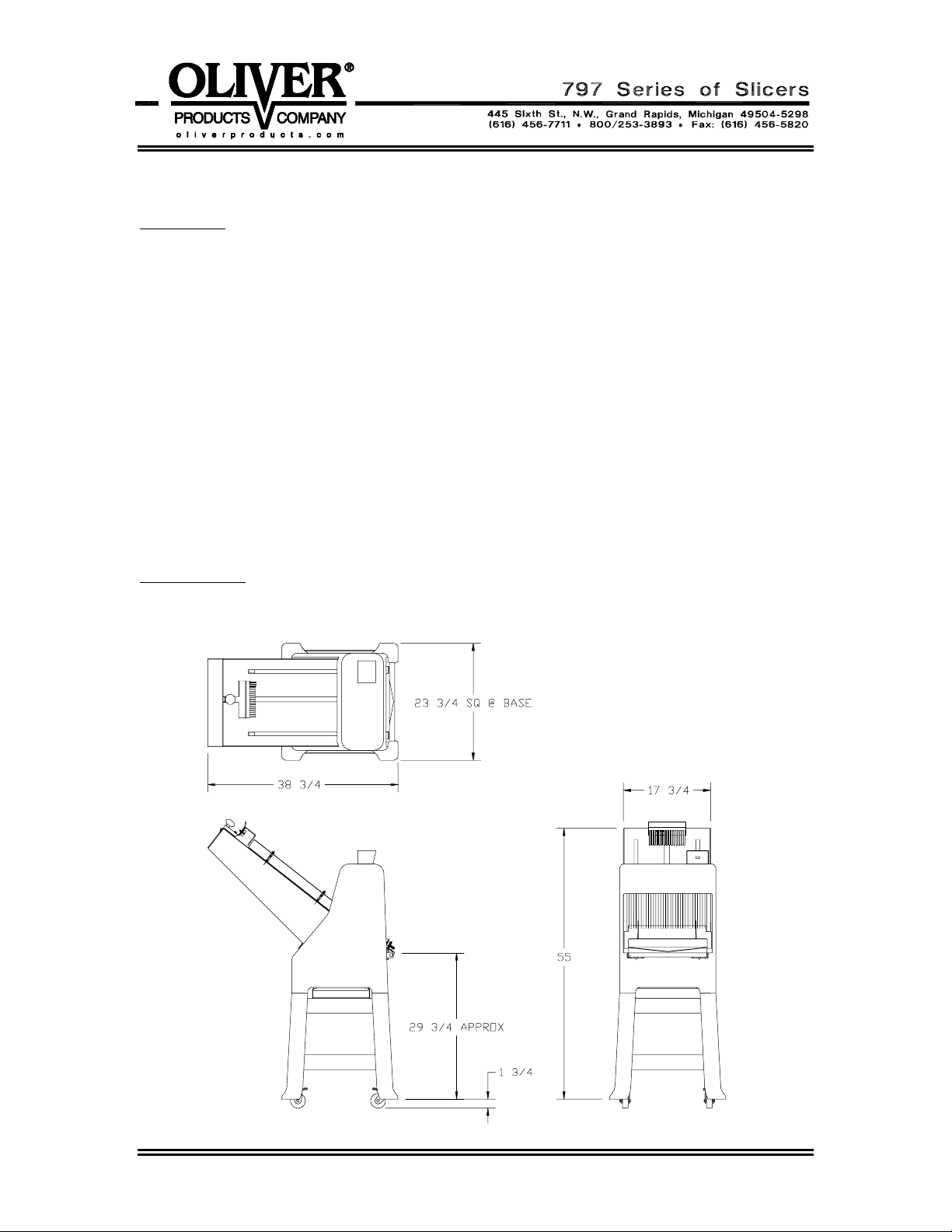
Specifications
Space Requirements: Model 797-32C, (All Dimensions are Approximate)
0797S20089 2-1

Product Capacities:
Up to 16 inches long and in the range of 2 to 5-1/2 inches high.
Standard Electrical Options: (Others available at additional cost -- consult factory).
1 phase, 60 hz, 115VAC, 7 Amps.
1 phase, 60 hz, 230VAC, 3.5 Amps.
Standard Slice Spacings
1/2, 9/16 (inches)
Optional Slice Spacings, (At additional cost). (Specials available -- consult factory 1/2” Min.).
5/8, 11/16, 3/4, 13/16, 7/8, 1, 1-1/4 (inches)
Shipping Weight, (All Weights are Approximate)
797-32C = 320 lbs.
797-48C = 380 lbs.
0797S20089 2-2
INSTALLATION INSTRUCTIONS
Removing the Slicer from the Shipping Skid
After removing the carton you should find the basic slicer completely assembled and
strapped to the shipping skid. Cut both straps to free the slicer from the skid.
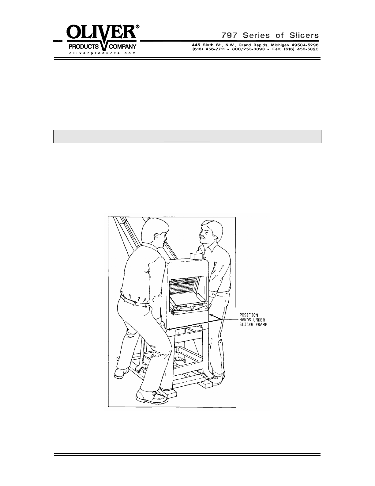
CAUTION
THE SLICER IS HEAVY, USE PROPER TECHNIQUE WHEN LIFTING.
KEEP BACK STRAIGHT, KNEES BENT, AND LIFT WITH LEGS.
USE GLOVES TO PROTECT HANDS.
As shown in the illustration below, lift the slicer off the shipping skid with one person
standing on each side of the slicer. Set the slicer down on a level floor after which it may
be moved to the desired location.
Rev. 8/3/04
0797S20090 3-1
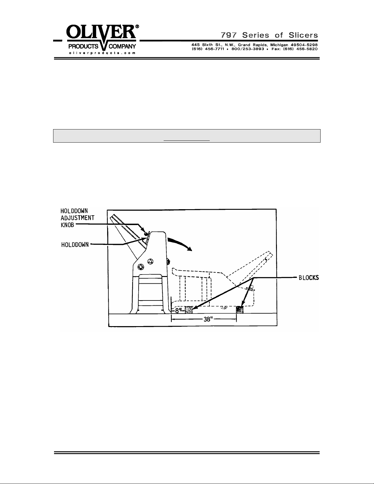
CASTER INSTALLATION INSTRUCTIONS
Place blocks on the floor approximately (8) and (38) inches from the discharge side of
the slicer, see the illustration below. Lower the holddown to its lowest position and
tighten the adjustment knob to prevent the outfeed table from swinging out. With one
person on each side of the slicer, gently lower the slicer onto the blocks.
CAUTION
NEVER ATTEMPT TO LIFT THE SLICER BY ITS INFEED CHUTE
AS DAMAGE TO THE MACHINE MAY RESULT.
Locate the casters, ¼-inch bolts, lock washers, and nuts in the option package. Install
the casters using the furnished hardware as shown in the figure on the next page tighten
the bolts and nuts securely using two wrenches. Install both locking casters on the
discharge side of the machine. See the next illustration. Set the brakes tightly on both
locking casters, (this will help to keep the wheels from rolling when lifting the slicer back
to its upright position).
Install the two rigid casters in the same manner on the infeed side of the slicer.
Rev. 8/3/04
0797S20090 3-2
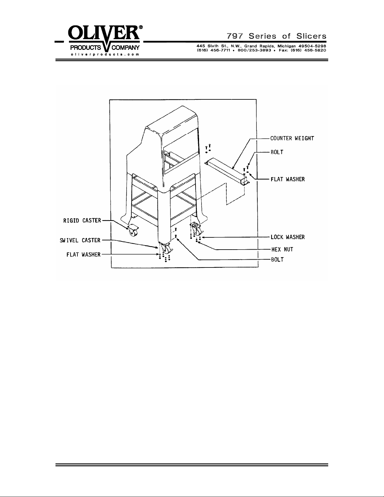
On all slicers equipped with either the Power Belt infeed chute option, or a Model 1179S
bagger, a counter weight must be attached to the caster brackets on the right hand side
of the machine, (as viewed from the outfeed side of the slicer). See the above
illustration. This counter weight must not be removed. Use the same hardware used to
secure the weight to attach the casters when both are used. Add additional bolts,
washers and nuts on those caster plate holes not involved with the weight mounted as
shown. Install one rigid caster and one swivel caster on the right hand side of the
machine, (the weight side). Remember, the rigid casters must be installed on the infeed
side of the machine.
Install the remaining two casters as previously described, setting their brakes tightly.
After completing the installation, chock the locked wheels using a 2 x 4 to ensure that
they will not roll or skid when lifting the slicer back to the upright position. Once the
machine is upright release the brakes and roll the slicer to its desired location.
Rev. 8/3/04
0797S20090 3-3
OPERATING INSTRUCTIONS
CAUTION
ALWAYS USE CARE WHENEVER WORKING NEAR THE CUTTING KNIVES.
Using the Slicer’s Holddown
These machines are equipped with a gravity style holddown which will self adjust to
product height. The holddown function is important because it will stabilize the product
during slicing.
Therefore, short products which do not contact the holddown may not slice well on this
machine. Products which are too tall to pass beneath the holddown must be
repositioned to allow passage. If they can not be repositioned to allow passage then the
product is outside the range that this machine can effectively slice.
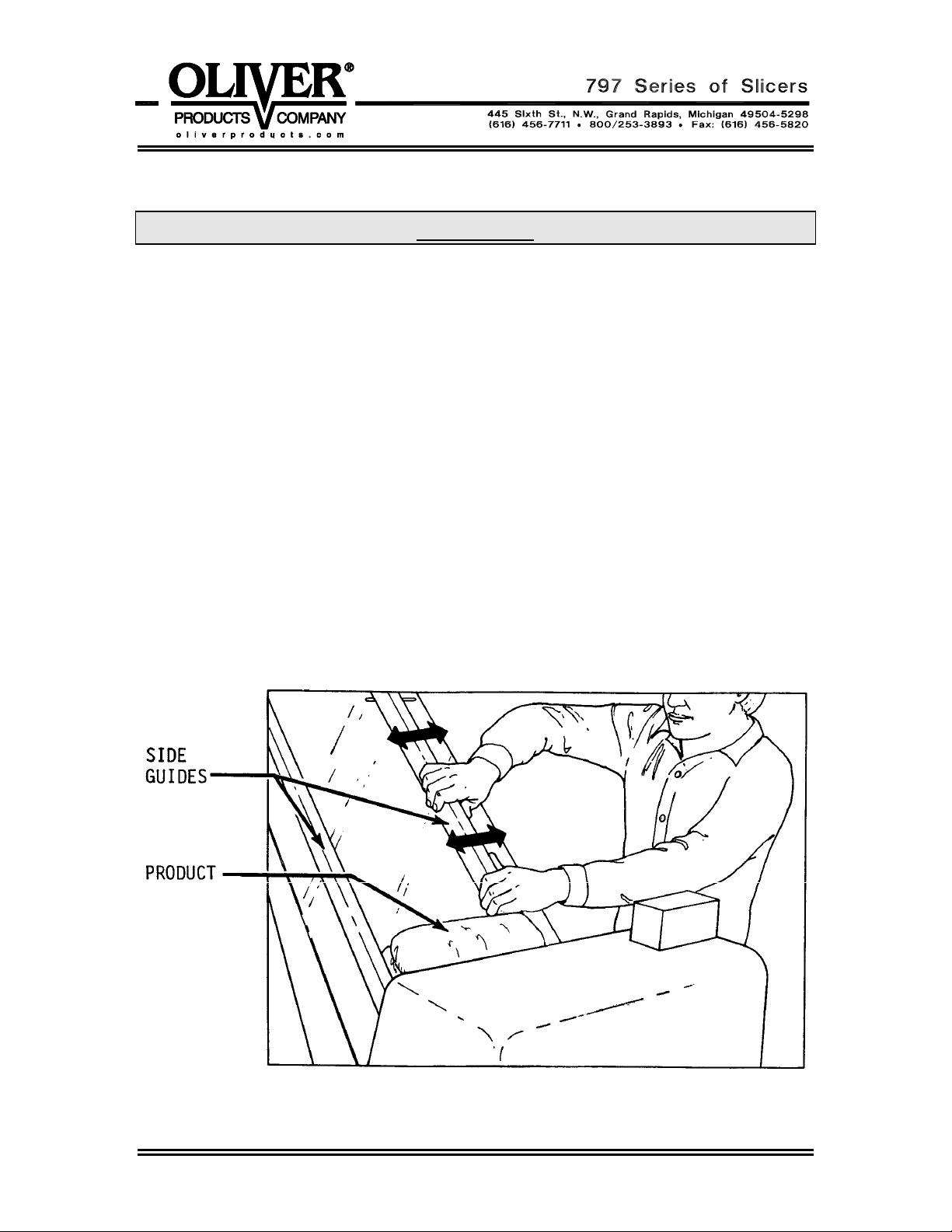
Adjusting the Slicer for Product Length
Using a typical product, adjust the infeed chute side guides by applying hand pressure.
See the next illustration. Set the side guides approximately 1/8 inch wider than the
longest expected product.
0797S20091 4-1
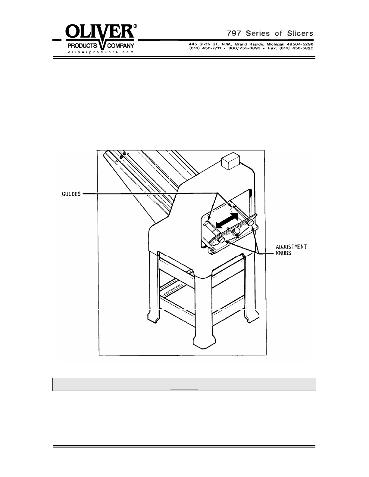
Adjusting the Outfeed Side Guides on a Standard Outfeed Table
Adjust the side guide extensions so that they are approximately 1/4 inch from the cutting
knives. Loosen the outfeed guide adjustment knobs. Adjust the outfeed side guides to
align with the infeed guides. See the illustration, which follows. Once satisfied with the
location re-tighten the side guide adjustment knobs. Proper adjustment of these guides
will keep the end slices from falling over as the product exits the cutting knives.
NOTE
OPTIONAL OUTFEED TABLE GUIDES ARE ADJUSTED WITH HAND
PRESSURE IN A FASHION SIMILAR TO THAT OF THE INFEED GUIDES.
AS WITH THE STANDARD OUTFEED TABLE ALIGN THE OUTFEED
GUIDES WITH THE INFEED GUIDES.
0797S20091 4-2

Operating a Gravity Feed Slicer
Once the slicer has been properly adjusted for the product, the infeed chute may be
loaded with the product to be sliced. Flipping the starting switch to the ON position will
begin operation. Remove each sliced product from the discharge table as it is sliced.
NOTE
THE GRAVITY FEED SLICER’S OPTIMUM OPERATING EFFICIENCY WILL
BE MAINTAINED BY ENSURING THAT THE INFEED CHUTE IS KEPT
FULLY LOADED. THE ACTUAL SPEED OF SLICING IS DEPENDENT ON THE
NUMBER OF PRODUCTS IN POSITION ON THE INFEED CHUTE, SHARPNESS
OF CUTTING KNIVES, AND TEXTURE OF THE PRODUCT.
Using the Last Loaf Pusher
These slicers are equipped with a Last Loaf Pusher which travels down the center of the
infeed chute. The Last Loaf Pusher is manually moved into position and can be allowed
to simply travel behind the last loaf loaded on the chute. The pusher’s added weight will
speed slicing. Manually return the Last Loaf Pusher to its upper position where a spring
clip will hold it in place after use or before reloading the infeed chute.
The Last Loaf Pusher can also be used to allow your production slicer to function as a
single loaf on demand slicer. Simply place the loaf on the chute in front of the knives
move the pusher into position, and then start the machine by flipping the on/off switch.
You may simply let the pusher’s extra weight push the bread trough the knives or you
may add additional pressure by using the hand knob on the pusher.
CAUTION
FORCING THE BREAD FASTER THAN THE KNIVES CAN CUT IT CAN CAUSE
DAMAGE TO THE KNIVES AND OTHER COMPONENTS OF YOUR SLICER.
CAUTION
THE KNIVES ARE EXTREMELY SHARP.
DO NOT TOUCH MOVING OR STATIONARY KNIVES.
0797S20091 4-3

TROUBLESHOOTING
WARNING
ALWAYS DISCONNECT THE SLICER FROM THE POWER SUPPLY BEFORE
ATTEMPTING ANY TYPE OF MAINTENANCE TASK, INCLUDING
TROUBLESHOOTING.
The Slicer Will Not Start (Motor Is Not Humming)
• The machine is not plugged in.
• There is no power at the outlet. (Check by plugging in a small working appliance,
like a lamp. Check to see if a circuit breaker has tripped. If the circuit breaker has
not tripped and the circuit is still not working have a qualified electrician check the
circuit.)
• The motor switch overload has tripped. (To reset push firmly in the direction shown
on the switch nameplate.)
• There are breadcrumbs in the motor starting switch. (Have a qualified electrician
disassemble the switch and clean it.)
• The problem is somewhere in the electrical system of the machine. (Have a qualified
electrician find and repair the problem.)
The Slicer Will Not Start (Motor Is Humming)
CAUTION
DO NOT ALLOW THE MOTOR TO HUM WITHOUT STARTING.
OVERHEATING CAN PERMANENTLY DAMAGE THE MOTOR.
• The motor has failed. (Have it checked by a qualified electrician.)
NOTE
A SPECIAL NON-VENTILATED MOTOR MUST BE USED WITH THIS SLICER.
• The drive system is binding. (Have a qualified service agent check for defective
bearings or other restrictions to free movement.)
• There is mechanical interference between other parts of the slicer. (Have a qualified
service agent evaluate the machine for adjustment or replacement of defective
parts.)
0797S20092 5-1

Bread Slices Vary in Thickness
• The blade frames are out of adjustment. (See the “Maintenance” section of this
manual under “Adjusting the Blade Frames When Slices Vary in Thickness” on how
to correct this problem.)
The Blade Frames Are Knocking
• The blade frames are out of adjustment. (See the “Maintenance” section of this
manual under “Adjusting the Clearance Between the Blade Frames” on how to
perform this adjustment.)
The Slicer Vibrates Excessively
• The drive belt is loose or worn. (See the “Maintenance” section of this manual under
“Tightening the Belt” or “Replacing the Belt” on how to make these corrections.)
• One or more of the bearings on the machine are failing. (Have a qualified service
agent check for defective bearings and replace them as required.)
• The pins, (two eccentrics and two regular), and links at the top of the blade frames
are worn. We suggest that these be replaced together. Mixing worn parts with new
will shorten the life of the replacement parts. Remember, after replacing the pins
and links the clearance between the blade frames must be re-adjusted. (See the
“Maintenance” section of this manual under “Adjusting the Clearance Between the
Blade Frames” on how to perform this adjustment.)
The Bread is Cutting Slowly or is Being Damaged
• The machine’s holddown is either missing or binding and thus not moving freely.
(See the “Operating Instructions” section of this manual under “Using the Slicer’s
Holddown”.
• The knives of the machine have become worn, (dull). (See the “Maintenance” section
of this manual under “Changing the Cutting Knives”). Most owners can perform this
item of maintenance without calling a service company.
• The blades are not aligned properly. (See the “Maintenance” section of this manual
under “Adjusting the Clearance Between the Blade Frames” on how to perform this
adjustment.)
0797S20092 5-2

MAINTENANCE
WARNING
ALWAYS DISCONNECT THE SLICER FROM THE POWER SUPPLY BEFORE
ATTEMPTING ANY TYPE OF MAINTENANCE TASK.
Cleaning
Use a mild detergent solution to clean all exterior surfaces and empty the crumb tray
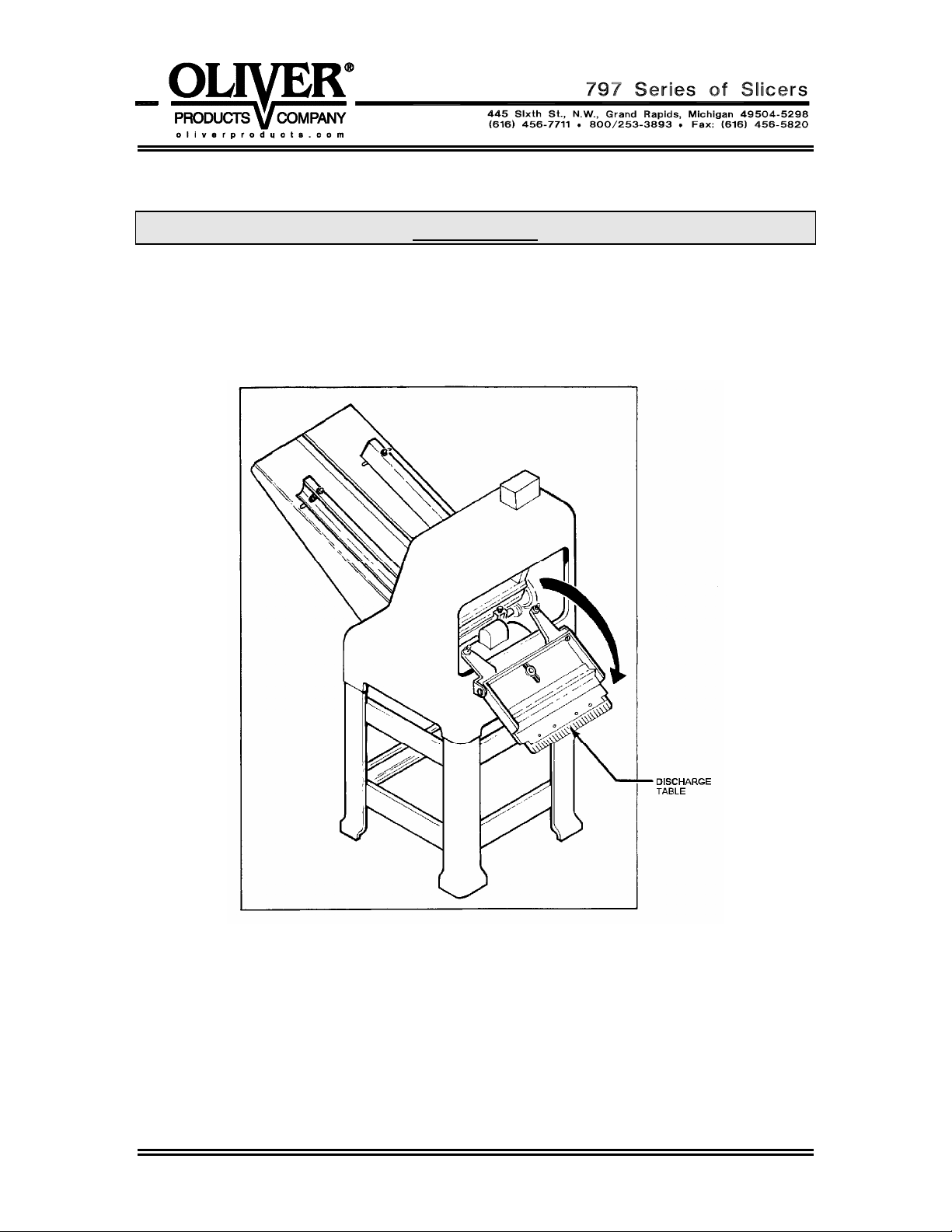
daily or more often if necessary. Periodically swing out the discharge table to allow
access to the drive area of the machine, then brush, blow, (if compressed air is
available), or wipe all foreign material from all surfaces, especially from moving parts.
Lubrication
Once a month, more often during heavy use, put a drop of food approved lubricant on
each of the pivot points, of the plastic links, located at the top to the blade frames. All
other bearings are either grease packed or sealed and seldom need attention.
CAUTION
NEVER OIL OR GREASE THE MOTOR.
0797S20093 6-1
Removing the Blade Frames
WARNING
ALWAYS DISCONNECT THE SLICER FROM THE POWER SUPPLY BEFORE
ATTEMPTING ANY TYPE OF MAINTENANCE TASK.
Swing out the discharge table from the slicer. See the next illustration.
Always start by removing the discharge side blade frame first. Both blade frames should
be removed from the discharge side of the machine. You should remove the discharge
side blade frame completely from the machine before starting on the infeed side blade
frame. However each is removed using similar procedures.
0797S20093 6-2
 Loading...