

Page 1

Walker, Michigan, U.S.A. 49534-7564
USER’S OPERATING AND INSTRUCTION MANUAL
MODEL SIMPLEX 4-24
SHEETER/ MOLDER
0424S20000-CVR
Page 2

Page 3
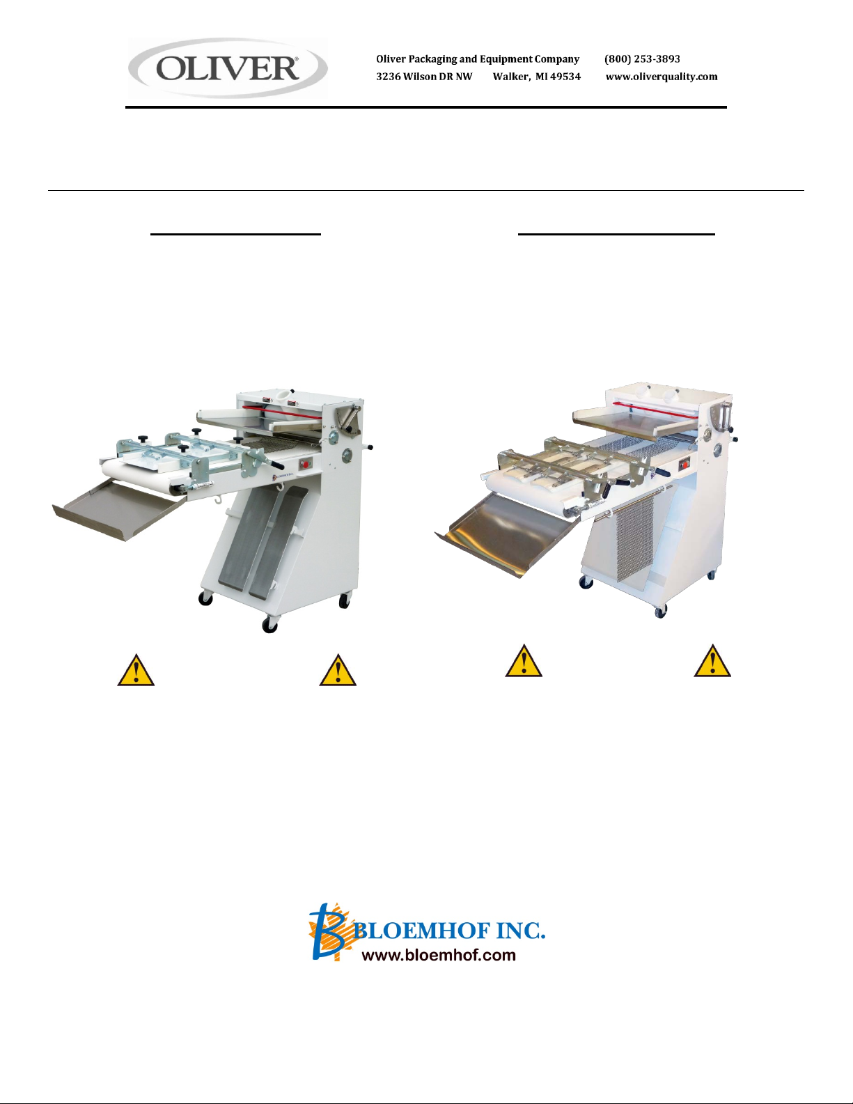
SIMPLEX 4-24 ~ 4-24-5 ~ 4-24BL1 ~ 4-24BL2
SHEETER / MOULDER
Operator’s Manual
Safety instructions
Maintenance & Trouble Shooting
Gear Motor Maintenance Instruction
Parts Diagrams & Warranty
Manual de Operación
Instrucciones de Seguridad
Instrucciones Mantenimiento
Problemas de Operación
Diagramas & Garantia
ATTENTION
All Operators
Do not install, operate or do maintenance on this
equipment without reading the manual of operation.
Protect yourself and others by observing all safety
procedures. Failure to comply with the instructions
may result in injuries and/or property damage.
SAFETY DEPENDS ON YOU!
MANUFACTURER OF QUALITY BAKERY EQUIPMENT SINCE 1960
Trademark(s) owned by Bloemhof Industries Ltd.
Toll Free 1-800-253-3893
Oliver 3236 Wilson Dr NW, Walker MI 49534
Tel 616-356-2950
ATENCIÓN
Todos los operadores
No Instale, opere o dé mantenimiento al equipo, sin la
previa lectura de este Manual de operación. Protéjase a
usted y a los demás cumpliendo con la información de
seguridad. La falta de cumplimiento de estas instrucciones
puede causar lesiones en su persona y/o daño a la
máquina.
LA SEGURIDAD DEPENDE DE USTED!
Fabricante de Manquinaria de Calidad Para Panaderias Desde 1960
Page 4

WELCOME TO BLOEMHOF
•
•
•
•
•
•
You have just p urchased one of the mos t reliable Sh eeter
/ Moulder that money can buy. The instructions are in
general because of the nationwide distribution of the
BLOEMHOF SIM PL EX S E R IE S, per sonal pr eferenc e with
regards to dough consistency, bread types and most
important, secret formulas.
The BLOEMHOF SIMPLEX SERIES of Sheeter /
Moulders includes several models as per the following:
• SIMPLEX 4-24 comes with 1 set of sheeting rollers & 4’
long bed
• SIMPLEX 4-24-5 comes with 5’ long bed & longer
pressure plates
• SIMPLEX 4-24 BL1 comes with one Bolillo (tapered
roll) curved plate
• SIMPLEX 4-24 BL2 comes with two Bolillo (tapered
roll) curved plates
The BLOEMHOF SIMPLEX SERIES will be a welcome
addition to your shop s ince it was des igned to reduce the
labour intensive and tedious sheeting and moulding
operations. W e invite you to r ead the instr uctions i n order
to obtain maximum performance, safety and satisfaction
from this outstanding unit.
The BLOEMHOF SIMPLEX SERIES features:
• OVERSIZED non-stick dough rollers with rust free
scrapers
• Fixed rollers for PRECISION SHEETING
• QUICK ADJUSTABLE in-feed pan arms
• Double pressure pla te controls front and back
models)
• Heavy duty motor and drive system
• Sanitary construction
IMPORTANT
NCRATING
U
This machine was carefully manufactured, tested and
crated prior to shipment. When uncrating this machine,
carefully inspect f or any shippi ng damage. M ake sure any
bolts or parts that may have loosened during transit are
tightened before proceeding.
SURE TO PREPARE YOUR PRESSURE PLATE
BE
WELL BEFORE THE FIRST USE!
The fabric surf aces of the pr essur e plates and r eturn plate
should be conditioned or seasoned before the first use.
Remove the pressure plate(s) and return plate from the
moulder and rub flour into the f abric even ly. Tur n over the
plate(s) and tap out excess flour. T his will conditioned or
seasoned the fabric to red u c e doug h s ticking. Once done,
reinstall the plate(s) as per instruction and start m oulding.
See pressure plate removal on page 5, number 7b.
(some
BIENVENIDO A BLOEMHOF
Usted acaba de adquirir una de las más confiables
Laminadoras / Mold eadora s que el di nero pu ede compr ar.
Las instrucciones so n generales debido a: la distr ibución
nacional de la SERIE SIMPLEX BLOEMHOF, la
preferencia con respecto a la consistencia de la masa,
tipos de pan, y lo más importante, fórmulas secretas.
Características de la SERIE SIMPLEX BLOEMHOF
• SIMPLEX 4-24 viene con un juego de rodillos
laminadores y una base de 4’ de largo
• SIMPLEX 4-24-5 viene con un depósito de 5’ de largo
y placas de presión más largas
• SIMPLEX 4-24 BL1 viene con una placa curva para
Bolillo (panecillo cónico)
• SIMPLEX 4-24 BL2 viene con dos pl acas c urvas para
Bolillo (panecillo cónico)
La SERIE SIMPLEX BLOEMHOF será un bienvenido
anexo para su establecim iento, ya que fué diseñada para
reducir las laboralmente int ens ivas y tediosas operac i ones
de laminado y moldeado. Le invitamos a que lea estas
instrucciones para obtener el máximo rendimiento,
seguridad y satisfacción de esta máquina sin par.
Características de la SERIE SIMPLEX BLOEMHOF:
Rodillos para m asa ant i-adhes ivos d e tam año EXTRA
GRANDE con espátulas libres de óxido
Rodillos fijos para LAMINADO DE PRECISION
Brazos del recipiente e n l a tol va p ar a e l ingr es o de los
alimentos RAPIDOS Y AJUSTABLES
La placa de doble presión controla el frente y dorso
(en ciertos modelos)
Motor y sistema de transmisión de uso intensive
Construcción sanitaria
AL DESE MBALAR
Esta máquina fue cuidadosamente manufacturada,
probada y empacada previo a su embarque. Cuando
desembale esta máquin a, inspeccionéla cuidadosamente
por cualquier daño ocasionado durante el traslado.
íASEGURESE DE PREPARAR SU PLACA
DE PRESION BIEN DE ANTEMANO
Las superficies del tejido sobre la placa de presión y la
placa de reingreso deberían ser condicionadas o
aclimatadas antes de su primer uso. Remueva la/las
placas de presión, y la placa de reingreso en la
moldeadora, y friegue harina unif ormemente hacia dentro
de la tela. Dé vue lta la/las placas y remueva tod o exceso
de harina. Esto c ondicionará o aclimatará el tejido a fin
de reducir adherencia de la masa. Una vez efectuados
estos pasos, re-instale la o las placas de acuerdo a las
instrucciones provist as, y comienze a moldear. O bserve
el removido de las placas de presión, tal como se detalla
en la página 5, número 7b.
IMPORTANTE
PREVIO AL PRIMER USO!
2
Page 5

SAFETY INSTRUCTIONS
INSTRUCCIONES DE SEGURIDAD
WARNING!
DO NOT INSTALL OPERATE OR MAINTAIN THIS EQUIPMENT
WITHOUT READING AND UNDERSTANDING THIS MANUAL
SAFETY DEPENDS ON YOU!
WARNING!
ELECTRICAL SHOCK CAN KILL
• Install equipment in accordance with the all
national and local electrical codes.
• Improper connection of the equipment
grounding conductor and line voltage can
result in a risk of electrical shock and / or
damage to equipment, (such damages are not
covered by warranty).
• Consult with a qualified electrician and / or
service person to ensure that the outlet is
properly grounded. Only a qualified electrician
can modify the electrical cord and / or plug-in
provided.
• Disconnect machine from electrical supply
source before performing any and all
maintenance.
GENERAL SAFETY INSTRUCTIONS
1. READ the Operators Manual carefully. Be thoroughly
familiar with the controls and the proper use of the
equipment.
NLY PERSONS well acquainted with these rules for
2. O
safe operation should be allowed to use this machine.
3. Do not wear loose clothing, scarves, or neckties.
These items may become caught in moving parts and
result in personal injury.
ISUALLY inspect machine prior to starting motor.
4. V
Ensure all safety guards, covers and devices are in
position and in good condition. Keep hands, hair,
clothing and tools away from rollers, V-belts,
conveyor belts and all other moving parts when
starting, operating or repairing equipment. Do not
disconnect Safety Bar or render it inoperable by tying
or taping it in a fixed position.
HE SAFETY BAR IS THERE FOR YOUR PROTECTION!
T
ISCONNECT machine from power supply before
5. D
performing servicing, maintenance, or cleaning. In
some cases it may be necessary to remove safety
guards to perform required maintenance. Immediately
replace guards before placing the machine into
service.
URN OFF machine control before unplugging. Do not
6. T
unplug machine and do not attempt to move the
machine by pulling cord.
O NOT operate machine when children are present
7. D
and disconnect power supply when unattended.
8. S
TAY ALERT! Watch what you are doing and use
common sense. Do not use the machine when you
are tired, distracted or under the influence of drugs,
alcohol or heavy medication.
ADVERTENCIA!
NO INSTALE, OPERE O HAGA TAREAS DE MANTENIMIENTO SOBRE
ESTE EQUIPO
UN CHOQUE ELECTRICO PUEDE M AT AR
• Instale el equipo conforme a toda codificación eléctrica
nacional y local.
• Una conexión incorrecta del conductor a tierra y línea de
voltaje del equipo puede resultar en riesgo de choque
eléctrico y/o daño al equipo. Tales daños no están
cubiertos por la garantía.
• Consulte un electricista calificado y/o persona de servicio
de reparación, a fin de asegurar que la salida esté
correctamente conectada a tierra. Unicamente un
electricista calificado puede modificar el cable eléctrico
y/o enchufe provisto.
• Desconecte la máquina de la fuente de suministro
eléctrico antes de realizar cualquier tarea de
mantenimiento
INSTRUCCIONES GENERALES DE SEGURIDAD
1. LEA el Manual del Operador cuidadosamente. Esté
exhaustivamente familiarizado con los controles y el uso
correcto del equipo.
2. SOLAMENTE PERSONAS bien familiarizadas con estas
reglas deberían ser autorizadas a usar esta máquina.
3. NO VISTA indumentaria suelta, bufandas o corbatas, ya que
estas prendas pueden quedar atrapadas en partes móviles de
la máquina, y provocar lesions personales.
4. INSPECCIONE VISUALMENTE la máquina antes de encender
el motor. Asegúrese que todos los dispositivos de seguridad,
cubiert as, aparejos y c omponentes es tén en posici ón correcta
y en adecuadas condiciones. Mantenga sus manos, pelo,
indumentaria y herramientas alejados de los rodillos, correas,
cintas transportadoras, como así también las demás partes
móviles, al encender, operar o reparar la máquina. No
desconecte la Barra de Seguridad o tórnela inoperable
mediante su atadura o pegándola con cinta adhesive en una
posición fija.
¡LA
5. DESCONECTE la máquina del suministro de energía antes de
realizar tareas de reparación, mantenimiento o limpieza. En
algunos casos quizás será necesario remover los dispositivos
de seguridad para poder efectuar el trabajo de mantenimiento
requerido. Inmediatamente reemplaze estos dispositivos antes
de cualquier tarea de mantenimiento.
6. APAGUE el control de la máquina antes de desenchufarla. No
desenchufe la máquina y no intente moverla mediante el jalón
del cable.
7. NO opere la máquina cuando niños se encuentren cerca de
ella y desconéctela cuando no esté en servic io
8. MANTENGASE
haciendo y utilize su sentido común. No use la máquina
cuando usted está cansado, distraído, o bajo la influencia de
drogas, alcohol, o fuertes medicamentos.
, SIN ANTES HABER LEIDO Y ENTENDIDO ESTE
MANUAL
.
LA SEGURIDAD DEPENDE DE USTED!
ADVERTENCIA!
BARRA DE SEGURIDAD ESTA ALLI PARA SU
PROTECCION!
ALERTA! Preste atención a lo que está
3
Page 6

MOULDING BREAD AND BUNS
1. ELECTRONIC SPEED ADJUSTMENT (When
supplied)
Set to maximum speed for moulding and minimum
speed for sheeting.
2. START/STOP STATIONS
Start/stop stations are located on each side of the
conveyor box.
3. SAFETY BAR
The safety bar is located in front of the dough rollers
and is connected to an interlock switch. Prior to daily
use, check proper operation of the safety bar by
starting the machine and stopping the machine by
lifting the safety bar. The safety bar should never be
removed or restricted of motion in any manner.
4. IN-FEED PAN ARMS
Position arms evenly from the center so that dough
enters the pressure plate dead center. For long
loaves, these arms should be farther apart in order to
feed the dough wider. When the dough roll enters the
pressure plate, it should not be longer than the width
of the pressure plate. If it is, position arms closer
together.
5. TELECOPING IN-FEED TUBE
The telescoping in-feed tube is designed for feeding
small dough pieces. For moulding small dough pieces,
loosen the black knob and lower the telescoping tube.
For bread moulding or sheeting, raise the telescoping
tube.
6. ROLLER GAP SETTING
The number that the control panel handle will be set at
will vary according to the weight of the product being
moulded, formulas and dough consistency. Since
softer dough requires less roller gap than stiff dough,
the control panel will be set at a smaller number for
soft dough.
7. CU RLING CHAIN:
The large curling chain is used for bread moulding.
8. PRESSURE PLATE
Position the Pressure Plate assembly in the “down”
position and lock into the hold down pins on the sides
of the machine by pulling the pressure plate assembly
toward the catch tray.
MOLDEANDO PAN Y BOLLOS
1. AJUSTE DE VELOCIDAD ELECTRONICO (cuando suministrado)
Fije a máxima velocidad para el moldeado y mínima
velocidad para el laminado.
2. DISPOSITIVOS START/STOP (ENCENDIDO/APAGADO)
Localizados a ambos lados de la caja transportadora.
3. BARRA DE SEGURIDAD
La barra de seguridad está localizada al frente de los rodillos
de amasar y está conectada al interruptor de bloqueo interno.
Previo a su uso diario, verifique la correcta operación de la
barra de control al encender y apagar la máquina mediante la
elevación de la barra de seguridad. La barra de seguridad
jamás debería ser removida o restringida de movimiento en
modo alguno.
4. BRAZOS DEL RECIPIENTE EN LA TOLVA PARA EL
INGRESO DE LOS ALIMENTOS
Posicione los brazos equitativamente desde el centro a efectos
de que la masa entre por la placa de presión exactamente por
el centro de la misma. Para hogazas largas, estos brazos
deberían estar posicionados aún más lejos de cada uno, para
poder de esa manera ingresar la masa de por un espacio más
ancho. Cuando el rollo de mas a ingresa a la placa de presión,
no debería ser más largo que el ancho de las placas de
presión. Si acaso lo fuera, coloque los brazos más cerca de
cada uno.
5. TUBO TELESCOPICO PARA EL INGRESO DE ALIMENTOS
Este está diseñado para poder alimentar pequeñas piezas de
masa. Para el moldeo de pequeñas piezas de masa, afloje la
manija negra y descienda el tubo telescópico. Para el moldeo
o laminado de pan, eleve este tubo.
6. FIJACION DE LA ABERTURA DEL ROLLO
El número al que el panel de control será fijado variará según
el peso del producto que se esté moldeando, las fórmulas y la
consistencia de la masa. Dado que la masa más suave
requiere de menos abertura de rollo que la masa rígida, el
panel de control será fijado a un número más pequeño para
masa suave.
7. CADENA ENROLLADORA
La amplia cadena enrolladora es utilizada para el
moldeo de pan.
8. PLACA DE PRESION
Posicione el ensamb laje de la Placa de Presió n en la
posición ‘down’ (‘abajo’) y tranque las clavijas laterales
de la máquina hacia abajo, mediante el jalón del
ensamblaje de la placa de presión hacia la bandeja de
salida.
4
Page 7

The pressure plate settings will vary according to
dough weights, formulas, consistency and size. Too
much pressure (i.e. too little space between the
pressure plate and belt) may tear the dough and ca use
excessive crumbs.
On some model the pressure plate s ystem has c ontr ol
handles at the front and back of the pressure plate
system. If supplied with the two handle system, the
pressure plate can be slightly angled so that the gap
between the back of the pressure plate and conve yor
belt is slightly less than the front end. This offers better
dough control.
NOTE: The pressure plate should never be
adjusted with the front end closer to the conveyor
belt than the back end as this will give the dough a
rough outer appearance.
9. SIDE GUIDES
24BL2)
The side guides sh ould be adjusted a gainst the
(Side guides are not supplied with the 4-
pressure plate.
HOT DOG BUNS
1. Install 6” pressure plate and adjust pressure plate
setting as required.
2. Use light curling chain provided for buns.
3. Position control panel setting for dough t ype. The
gap between the dough r ollers should be sufficient
to degas but not tear or punish the dough piece.
4. Position tra y of cut dou gh pieces on top of pressur e
plate system.
5. Lower telescoping in-feed tube by loosening black
knob.
6. Stretch the dough piece s l i ghtly before dropping into
in-feed tube.
SHEETING
For use of the Simplex as a SHEETER, follow these
steps:
1. Move dough rollers to maximum gap for
SHEETING. Remove curling chain and store on
hooks provided under conveyor.
2. Move in-feed pan arms to maximum open position.
3. Store pressure plate system in “up” position, on
conveyor box.
4. Store pan with flour o n top of machine for ease of
flouring.
La fijación de la placa de presión variará de acuerdo a
pesos de masa, fórmulas, consistencia y tamaño.
Demasiada presión (c omo por ejem plo mu y poco espacio
entre la placa de presió n y la cint a) podrí a rasgar la m asa
y causar excesivas migajas.
En algunos modelos el sistema de placa de presión
posee manivelas de control en el frente y dorso del
mismo. De ser provisto con el sistema de las dos
manivelas, la placa de presión puede ser levemente
angulada para que la aber tura entre la parte tras era de la
placa de presión y la cinta tr ansportadora sea levemente
inferior al extremo delantero. Esto permitirá ejercer un
mejor control sobre la masa.
NOTA: Esta placa de presión jamás debería ser
ajustada con el extremo delantero más cercano a la
cinta transportadora que el extreme trasero, ya que
ello le daría a la masa un aspecto exterior áspero.
9. GUIAS LATERALES
(no suministradas con la 4-24bl2)
Estas deberían ser ajustadas contra las placas de
presión.
ROLLOS DE HOT DOG
1. Instale una placa de pres ión de 6 pulgadas y ajuste su
colocación de acuerdo a los requerimientos.
2. Use la cadena enrolladora liviana provista para rollos.
3. Posicione el panel de control según el tip o de masa. La
abertura entre los rodillos de masa debería ser lo
suficientemente generosa como para desgasear,
aunque no tanto que desgarre o arruine la pieza de
masa.
4. Posicione la bandeja con piezas de masa cortadas
encima del sistema de las placas de presión.
5. Descienda el tubo telescópico utilizado para el ingreso
de los alimentos al aflojar la perilla negra.
6. Estire la pieza de masa levemente antes de depositarla
dentro del tubo telescópico.
LAMINADO
Para uso del Simplex como LAMINADORA, siga los
siguientes pasos:
1. Mueva los rodillos de masa a efectos de permitir la
máxima abertura posible para el LAMINADO.
Remueva la cadena enrolladora y guárdela en los
ganchos provistos debajo de la cinta transportadora.
2. Mueva los brazos del recipiente en la tolva de ingre so
de los alimentos a la posición mas abierta posible.
3. Almacene el sistema de placas de presión en la
posición “up” (“arriba”) sobre la caja de la cinta
transportadora.
4. Almacene el recipiente de harina encima de la
máquina, para de ese modo facilitar el enharinamiento.
Page 8

5. Adjust potentiometer (when supplied), counterclockwise.
6. For sheeting, flo ur in-feed pan well and f eed dough
into rollers. Decrease ga p betwe en pressure r ollers
with each successive pass until desired dough
thickness is obtained.
7. While feeding dough into rollers, give a gentle
shove, being careful not to bunch the dou gh at the
rollers. Restraining slightly as the rollers pull the
dough will provide longer sheeted dough.
BOLILLO PRODUCTION
4-24BL1 and 4-24BL2
With optional curved pressure plate and
two handled pressure plate system
For production of Bolillo or tapered roll products, follow
these steps:
1. Install the curved Bolillo pressure plate(s) in
pressure plate system.
2. Install light curling chain(s) on machine.
3. Position control pane l setting for dough t ype. The
gap between the dough roller s should be suff icient
to degas but not tear or punish the dough piece.
4. For large dough pieces adjust in-feed guides on
in-feed pan so that the dough piece coming
through the dough rollers and under the curling
chain enters the pressure plate dead center.
5. Lower the in-feed tube(s) to the lowest position.
6. Adjust the pressure plat e handles on the pres sure
plate system, so that th e curved plate is closer to
the conveyor belt at the back or take off end, than
at the front or entr y end. The angle of th e curved
pressure plate relative to the conveyor belt will vary
according to dough types, product weight, dough
consistency and pro ofing tim e. Adjustments to the
front and back of the pr essure plate will have to be
made until the desire shape is obtained.
7. When feeding the dough ball into the telescoping
in-feed tube(s), it may be preferable to slightly
stretch the dough piece before dropping it into t he
telescoping tube. T his will cr eate a l onger sheeted
dough piece, resulting in a tighter curl and better
oven jump.
5. Ajuste el potenciómetro (cuando suministrado) en
6. sentido contrario a las manecillas del reloj
Para laminar, enharine bien el recipiente para el
ingreso de alimentos y agregue la masa en los ro dillos.
Aminore la abertura entre los rodillos de presión con
cada pasada sucesiva, hasta obtener el grueso de
masa deseado.
7. Al ingresar masa en los rodillos, dé un leve empujón,
asegurándose de no aglutinar de masa a los rodillos.
Restringiéndose lev em ente m ientras los ro dillos jalan la
masa, le proveerá de una pieza con laminado más
largo.
PRODUCCION DE BOLILLO
4-24BL1 y 4-24bl2
Con placa de presión curva opcional y sistema
Para la producción de Bol illos o panec illos cónic os, sig a los
siguientes pasos:
1. Instale la/las placas de pr esión curvas de Bol illos en el
sistema de placas de presión.
2. Instale la/las cadenas de enrollado en la máquina.
3. Posicione la fijación de l panel de control según el tipo
de masa. La abertura entre los rodillos de masa
debería ser suficiente para des gas ear pero no rasgar o
arruinar la pieza.
4. Para piezas grandes de masa, ajuste las guías de
ingreso en el reci piente de ingreso para que la pieza
de masa que llega a tra vés de los rodill os y por debajo
de la cinta enrolladora, ent re po r medi o d e la placa d e
presión.
5. Descienda el/los tubos par a el ingreso d e los alim entos
a la posición más baja posible.
6. Ajuste los mangos de las placas de presión sobre el
sistema de placas de presi ón, para que la placa curva
esté más cerca de la c int a t rans por tad ora en el extreme
trasero o de despegue, que del extrem e delanter o o de
ingreso. El ángulo d e la placa curva relativ o a la cinta
transportadora variar á de acuerdo a los tipos de m asa,
el peso del producto, la consistencia de la masa y
tiempo de aislamiento. Ajustes a los extremos
delantero y trasero de la plac a de presión deberán ser
hechos hasta que la forma deseada sea obtenida.
7. Cuando ingrese la bola de masa por el/los tubos
telescópicos para el ingreso del alimento, quizás sea
preferible el apenas es tirar la pieza de masa antes de
depositarla dentro del tubo telescópico. Esto creará
una pieza de masa con laminado más extenso,
resultando en un enrollado m ás apretado y
más rápida elevación de la masa.
de dos placas de presión
6
Page 9

TROUBLE SHOOTING
1. DOUGH TEARING
Cause: Excessive pressure on pressure rollers.
• Decrease setting on control panel handle.
• Increase space between pressure plate and
conveyor belt
2. EXCESSIVE CRUMBS
Cause: Too much pressure on pressure plate.
• Increase space between pressure plate and
conveyor belt
3. ONE SIDE LARGER
Cause: Un-centered feeding.
• Make sure in-feed guides are evenly divided
from the center.
• Bread must enter underneath pressure plate
dead center.
• The side guides mus t be equally divided from
or against the pressure plate.
4. DOUGH PIECE STALLS ON DOUGH ROLLERS
OR UNDER CURLING CHAIN
Cause
• Dough piece must not be f loured or have a dr y
surface. Spray dough pieces with water prior
to moulding.
• Increase roller gap between the dough rollers
by adjusting control panel handle to a higher
number.
5. LARGE HOLES IN BREAD
Cause: Surface of dough torn
• Surface of dough should not be torn after
passing through rollers. If it is, set control
panel handle to a higher number.
• Dough piece should be completely rolled up
before entering pressure plate. If not, set
control panel handle to a larger number.
6. BELT SLIPPING
Cause: Belt stretched or not adjusted.
• See maintenance instructions.
7. MOTOR STOPS
Cause: Motor overheatin g
• Unplug machine, wait 5 minutes. Check motor.
• Excessive dough buildup on belt. Clean belt
with plastic scraper. Do not use a steel
scraper!
• Side guides too close to belt, re-adjust.
• Too many dough pieces being worked by
machine at one time.
CAUSAS Y SOLUCIONES DE PROBLEMAS
1. RUPTURA DE LA MASA
Causa: Excesiva presión sobre los rodillos de presión.
• Aminore el nivel de ajuste en el panel de control.
• Incremente el espacio e ntre la p laca de pr esión y la
cinta transportadora.
2. EXCESIVA CANTIDAD DE MIGAJAS
Causa: Demasiada presión sobre la placa de presión.
• Incremente el espacio e ntre la p laca de pr esión y la
cinta transportadora.
3. UN COSTADO ES MAS GRANDE
Causa: La alimentación no está centrada.
• Asegúrese que las guías de alimentación estén
equitativamente divididas desde el centro.
• El pan debe ingresar exactamente a través del
centro y por debajo de la placa de presión.
• Las guías laterales deben estar igualmente
divididas desde o contra la placa de presión.
4. LA PIEZA DE MASA SE ATORA SOBRE LOS RODILLOS O
DEBAJO DE LA CADENA ENROLLADORA
Causa
• La pieza de masa no debe ser enharinada ni su
superficie estar seca. Rocíe las piezas de masa
con agua previo a su moldeo.
• Incremente la abertura de rodillo entre los rodillos
de masa mediante el ajuste de la manivela del
5. GRANDES HOYOS EN EL PAN
6. LA CINTA RESBALA
7. EL MOTOR SE DETIENE
panel de control a un número más elevado.
Causa: La superficie de la masa está rasgada.
• La superficie de la m asa no debería estar rasgada
luego de haber pasa do a través de los rod illos. Si
acaso lo está, ajuste la m anija del panel de cont rol
a un número más alto.
• La pieza de masa debería estar completamente
enrollada antes de ingres ar por la plac a de presión.
De no ser así, fije el pan el de control a un núm ero
más grande.
Causa: La cinta está demasiada estirada o no
adecuadamente ajustada.
• Vea las instrucciones de mantenimiento.
Causa: Sobrecalentamiento del motor.
• Desenchufe el motor, aguarde 5 horas Revise el
motor.
• Excesiva acumulación de masa en la cinta. Limpie
la cinta con una espátula de plás tico. ¡No use u na
espátula de acero!
• Las guías laterales están demasiado cerca de la
cinta. Reajústelas.
• Demasiadas piezas de masa están siendo
procesadas por la máquina a la vez.
7
Page 10

8. SCRAPER NOISE
Cause: Damaged scraper blades or installation
• Replace worn scraper blades.
• Make sure scraper assemblies are installed
properly.
9. ROLLER CHAIN NOISE
Cause: Dry roller chain
• Lubricate roller chain (See maintenance
instructions)
• Make sure the chain t ightener has not s eized.
If seized, remove and lubricate.
8. RUIDO DE LA ESPATULA
Causa: Las hojas de la espátula o la misma instalación
están dañadas.
• Reemplaze las hojas de espátula gastadas.
• Asegúrese que los ensamblajes de las espátulas
estén propiamente instalados.
9. RUIDO DE LA CADENA DE RODILLOS
Causa: La cadena está seca
• Lubrique la cadena de rodillos (Vea las
instrucciones de mantenimiento)
• Asegúrese que el tensor d e la cadena no se haya
aflojado. Si ello hubiese ocurrido, remuévalo y
lubríquelo.
Page 11

PREVENTATIVE MAINTENANCE
SCHEDULE
Warning make sure to ALWAYS disconnect the
equipment from the power supply before
performing any servicing, maintenance, and
cleaning!
DAILY
1. Safety Bar Inter-Lock Switch
Check proper operation of the inter-lock switch
before use by starting the m achine and l ifting on the
safety bar. If the m achine does not shut off, unpl ug
the machine and inspect the inter-lock switch.
Service or replace as required. Do not use the
machine if the inter-lock switch is defective.
2. Conveyor Belt Tracking
Check conveyor belt trac king. If belt should run to
one side, tighten nut o n the belt roll holder on the
side to which the belt is runnin g a ½ turn and loosen
the opposite end, ½ turn. The machine shoul d be
running during this operat ion and it may take a few
minutes for the belt to react to the adjustments.
Should belt slip occur, tig hten both nuts on the belt
roll holders equally. T he belt should r un in betwe en
the belt guides, which are located underneath the
machine. Do not over tighten the conveyor belt.
3. Conveyor Belt Cleaning
Clean belt daily wit h a plastic sc raper - Do not use
a steel scraper!
4. Remove and Clean Scraper Assemblies
Remove and clean scraper s. Back scraper can be
accessed through the back scraper access door.
Clean with damp c loth or plastic scraper to r emove
dough from blade. Do not use any sharp object
to clean the scraper blade or immerse scraper
assembly into water!
5. Remove and Clean Pressure Plates
Use a plastic scraper for cleaning. Wipe clean with
a dry cloth.
6. Cleaning Machine
Use a brush, air hose or dam p rag. Do not spray
machine down with water!!
EVERY MONTH
1. Oil Roller Chain
Use 50W chain oil for best result.
2. Check Oil Level in Speed Reducer
Remove top back scraper access door, to inspect
speed reducer. Remove fill er cap on s peed reducer,
oil should be present 5 inches f rom top of reducer.
Add Spartan EP 680 gear oil if required. Do not
over fill. Oil will com e out of breath er hole on filler
cap, if too much oil is put into reducer.
CRONOGRAMA DE MANTENIMIENTO
PREVENTIVO
Advertencia ¡SIEMPRE desconecte el equipo
antes de cualquier tarea de reparación,
mantenimiento y limpieza!
DIARIAMENTE
1. Interruptor de bloqueo interno para la barra de seguridad
Asegúrese que la operación del interruptor de bloqueo interno
sea la adecuada antes de su us o, mediante el encendido de
la máquina y la colocación de la barra de seguridad. Si acaso
la máquina no se apagara, desenchúfela e inspeccione el
interruptor de bloqueo interno. Repare o reemplaze según
requerido. No utilize la máquina si la barra de bloqueo
interno es defectuosa.
2. Rastreo de la Cinta Transportadora
Revise la cinta transportadora. Si acaso la cinta se corriese
hacia un lado, ajuste mediante una media vuelta la tuerca
ubicada sobre el lado de la agarradera hacia el cual se corre
la cinta, y desajuste una media vuelta la tuerca en el extremo
opuesto. La máquina debería estar en funcionamiento
durante esta operación, y podrían pasar algunos minutos
antes que la cinta reaccione a los ajustes. De ocurrir un
deslizamiento de la cinta, ajuste ambas tuercas sobre las
agarraderas de la cinta equitativamente. La cinta debería
pasar exactamente por medio de las guías de la cinta, que
están localizadas debajo de la máquina. No sobre-tense la
cinta transportadora.
3. Limpieza de la Cinta Transportadora
Limpie la cinta diariamente con una espátula de plástic o. ¡No
utilize una espátula de acero!
4. Remueva y Limpie los Ensamblajes de las Espátulas
Remueva y lave las espátulas. La espátula trasera puede ser
accedida por la puerta de acceso a la misma. Limpie con un
paño húmedo o espátula de plástico a fin de remover mas a
de la cuchilla. ¡No use objeto filoso alguno para limpiar la
hoja del raspador o inmerse el ensamble de la espátula
en agua!
5. Remueva y Limpie las Placas de Presión
Utilize una espátula de plásti co para su limpieza. Limpie con
un paño seco.
6. Limpiando la Máquina
Use un cepillo, manguera de aire o un paño húmedo. ¡No
rocíe la máquina con agua!
MENSUALMENTE
1. Aceite la Cadena de Rodillos
Utilize aceite de cadenas 50W para lograr un mejor resultado.
2. Revise el Nivel del Aceite en el Reductor de Velocidad
Remueva la puerta de acceso a la espátula superior trasera,
con el fin de inspeccionar el reductor de velocidad. Remueva
la tapa del filtro sobre el reductor de velocidad e inserte
alambre por dentro del reductor. El aceite debe estar
presente a 5 pulgadas de la cima del reductor. Agregue
aceite para engranajes Spartan EP 680, si requerido. No
sobrellene. El aceite saldrá a través del orificio de respiro en
la tapa del filtro, si ac aso demasiado aceite fuese colocado
dentro del reductor.
9
Page 12

EVERY TWO MONTHS
1. Roller Chain
Inspect roller chain and lubricate with 50 weight
chain oil, if required. Do not use grease on the
roller chain. A dry roller chain will cause premature sprocket wear.
2. Chain Tightener
Pull back on chain t ight ene r assembly and re leas e.
Chain tightener should “spring back”. If not,
remove assembl y from pivot pin and lubr icate with
anti-seize compound or grease.
3. Pressure Plate Clamping Bolts
Lubricate clamping bo lt or bolts on pressure plate
system with anti-seize compound or grease.
EVERY FOUR MONTHS
1. Lubricate Chain Tightener Pin
Use anti-seize compound or grease.
EVERY SIX MONTHS
1. Speed Reducer
Inspect oil level in speed reducer. To access
speed reducer, remove back panel (two black
knobs, 14 screws), remove filler cap on speed
reducer, insert wire into reducer, oil should be
present 5 inches from top of reducer. Add
SPARTAN EP680 gear oil if required. Do not over
fill. Oil will come out of breather hole on filler cap
if too much oil is put into reducer.
2. Control Panel Link Arms
Lubricate control panel link arms on adjustable
pressure roll holder system. The pivot points are
located on the contro l p an e l rod. Open the scraper
access door at the back of the machine and adjus t
the control panel index handle and observe pivot
point locations. Lubricate with anti-seize
compound or grease.
CADA DOS MESES
1. Cadena de Rodillos
Inspeccione la cadena de rodillos y lubríquela con
aceite para cadena de p eso 50, de ser necesario. No
engrase la cadena de rodi llos. Una cadena de rodillos
seca causará desgaste prematuro en el piñón.
2. Tensor de la cadena
Jale hacia atrás sobre el ensamble del tensor de la
cadena, y suelte. La cadena debería volver a su
posición original. Si ello no ocurriese, remueva el
ensamblaje de la clavija de pivote y lubrique con un
compuesto anti-agarre o grasa.
3. Pernos Sujetadores de las Placas de Presión
Lubrique el perno o pernos sujetadores sobre el
sistema de placas de presión con un compuesto antiagarre o grasa.
CADA CUATRO M ESES
1. Lubrique la clavija del tensor de la cadena
Utilize el compuesto anti-agarre o grasa.
CADA SEIS MESES
1. Reductor de Velocidad
Inspeccione el nivel del aceite en el reductor de
velocidad. Para acceder al reductor de velocidad,
remueva el panel sup erior trasero (dos perillas negras ,
4 tornillos), rem ueva la tapa del filtro sobre el reductor
de velocidad, inserte alambre hacia adentro del
reductor, y asegúrese que el nivel del aceite se
encuentre a 5 pulgadas de la tapa del reductor.
Agregue aceite para engranajes SPARTAN EP680, si
fuera necesario. No sobrellene. Aceite saldrá del
orificio de respiración en l a tapa del filtro, si dem asiado
aceite es colocado dentro del reductor.
2. Brazos Conectores del Panel de Control
Lubrique los brazos conectores del panel de control
mediante el sistema agarradero de presión de rodillo
ajustable. Los puntos de pivote se encuentran
ubicados en la vara del panel de contr o l. Abra la pu erta
del acceso a las espátu las que es tá ub icada en la part e
trasera de la máquina, ajuste el índice del panel de
control y observe las ubicaciones de los puntos de
pivote. Lubrique usando compuesto anti-agarre o
grasa.
Page 13

PARTS LIST AS PER DIAGRAM
When ordering parts please make sure to have the
following information available:
• The Simplex
ERIAL NUMBER ( Back panel of the machine, found
• S
on the name plate)
• Part Number and Quantity ( If unsure please contact
our Parts Person for help)
MODEL
PARTS CONTACT
Contact your local bakery equipment
service company
or
OLIVER 3236 Wilson Dr. Walker, MI 49534
Tel 1-800-253-3893 option 2,
Fax 616-456-7791
Cuando ordene repuestos, asegúrese de tener la
siguiente información disponible:
MODELO Simplex
• El
NÚMERO DE SERIE (ubicado en la parte posterior de
• El
la máquina, sobre la placa con su nombre)
• El código numeral y la Cantidad (por cualquier duda,
contacte nuestro personal de Repuestos para mayor
ayuda
11
Page 14
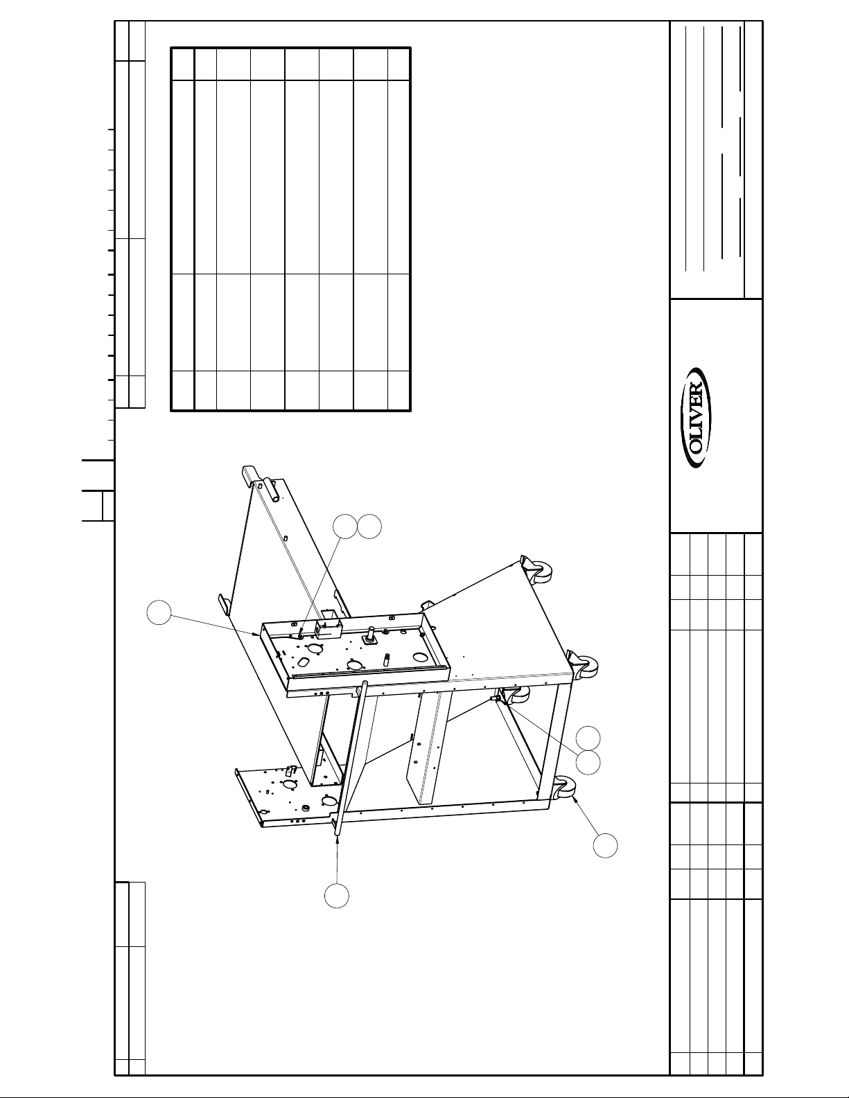
ITEM PART NUMBER DESCRIPTION QUAN.0 TOOL NAME NUMBER
Item Part Number Description Qty
0424 - 25001
C
1
4
8
8
4
1/10
DO NOT SCALE THIS DRAWING
FINISH
DATE SCALE
JCK 7-25-16
WITH COVER
STST
STST
SPRING
LOCK
1 0424-0001 WELDMENT, SIMPLEX FRAME 1
2 0424-0002 WELDMENT, SPROCKET BOX
3 5832-0524 NUT - HEX FULL 1/2-13NC FIN
4 5843-1000 SCREW- HEX HD 1/4-20 X 3/8
5 5851-9357 WASHER- LOCK 1/4 STST
6 5851-9361 WASHER-STST 1/2" SPRING
7 5902-2413 CASTER COLSON W/ BRAKE 4
SEE LIST
BASE FRAME ASSEMBLY
NAME
MAT'L
MAT'L NO.
DRAWN BY
WALKER, MICHIGAN, U.S.A. 49534-7564
REMOVE BURRS & SHARP EDGES
DIMENSIONAL TOLERANCES UNLESS SPECIFIED: FRACTIONAL ± 1/64; DECIMAL ± .005; ANGULAR ± 1°
CHANGE
THIS DRAWING AND ALL PROPRIETARY RIGHTS AND CONCEPTS HEREIN ARE
THE EXCLUSIVE PROPERTY OF OLIVER PACKAGING AND EQUIPMENT COMPANY AND ARE NOT
TO BE USED, DUPLICATED OR TREATED IN ANY WAY INCONSISTANT WITH
4
5
SUCH RIGHTS WITHOUT PERMISSION OF OLIVER PACKAGING & EQUIPMENT COMPANY.
2
6
3
LTR EC NO.BYDATECHANGE
SPROCKET BOX COVER OMITTED TO SHOW FASTENERS
7
1
LTR CHANGE DATE BY EC NO.
Page 15
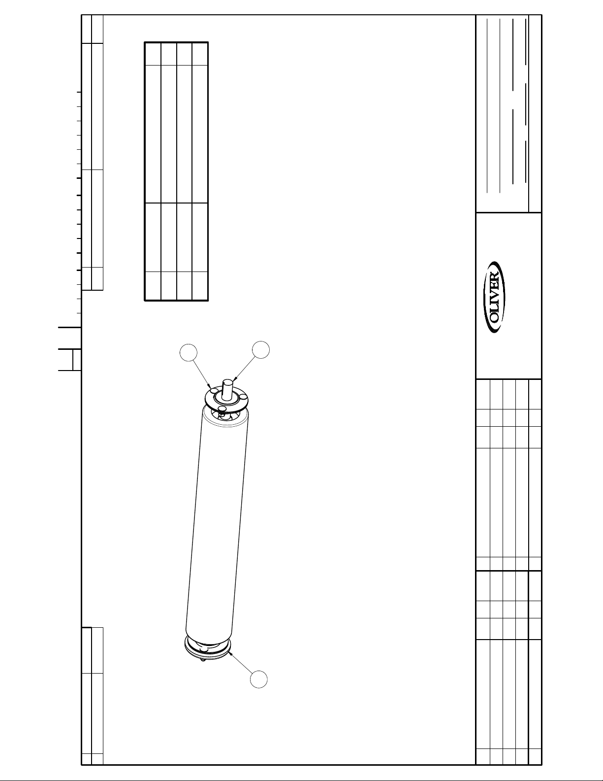
SEE LIST
ASSY, SIMPLEX FIXED DOUGH ROLLER
NAME
MAT'L
FINISH
MAT'L NO.
DO NOT SCALE THIS DRAWING
DATE SCALE
JCK 7-25-16
DRAWN BY
DIMENSIONAL TOLERANCES UNLESS SPECIFIED: FRACTIONAL ± 1/64; DECIMAL ± .005; ANGULAR ± 1°
REMOVE BURRS & SHARP EDGES
ITEM PART NUMBER DESCRIPTION QUAN.0 TOOL NAME NUMBER
0424 - 25002
C
CHANGE
Item Part Number Description Qty
1 0860-0002 FIXED DOUGH ROLLER ASSY 1
2 0860-0070 BEARING 3/4 W/COVER 1
3 0860-1197 BEARING ASSY .875 1
WALKER, MICHIGAN, U.S.A. 49534-7564
3
1
THIS DRAWING AND ALL PROPRIETARY RIGHTS AND CONCEPTS HEREIN ARE
THE EXCLUSIVE PROPERTY OF OLIVER PACKAGING AND EQUIPMENT COMPANY AND ARE NOT
TO BE USED, DUPLICATED OR TREATED IN ANY WAY INCONSISTANT WITH
SUCH RIGHTS WITHOUT PERMISSION OF OLIVER PACKAGING & EQUIPMENT COMPANY.
LTR EC NO.BYDATECHANGE
2
LTR CHANGE DATE BY EC NO.
Page 16
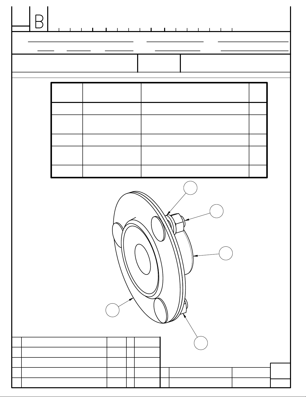
0860-1197
CHANGE
205 BEARING ASSEMBLY SEE LIST
NAME
DRAWN BY DATE
SAT 5-3-16 FULL
SCALE
MAT'L
MAT'L NO.
FINISH
CUT SIZE
THIS DRAWING AND ALL PROPRIETARY RIGHTS AND CONCEPTS HEREIN ARE
THE EXCLUSIVE PROPERTY OF OLIVER PACKAGING AND EQUIPMENT COMPANY AND ARE NOT
TO BE USED, DUPLICATED OR TREATED IN ANY WAY INCONSISTANT WITH
SUCH RIGHTS WITHOUT PERMISSION OF OLIVER PACKAGING & EQU IPMENT COMPANY.
DO NOT SCALE THIS DRAWING
Item
Part Number Description Qty
Number
1 5251-3946 NTN BEARING AELPF205-014W3 1
2 5251-3946
FLANGE
3 5804-1730 BOLT, CARRIAGE 5/16-18 X .75 3
4 5832-0521 NUT- HEX FULL 5/16-18NC FIN
5 5851-9358 WASHER-LOCK 5/16" STST 18-8 3
REMOVE ALL BURRS
AND
SHARP EDGES
DIMENSIONAL TOLERANCES UNLESS SPECIFIED: FRACTIONAL ± 1/64; DECIMAL ± .005; ANGULAR ± 1°
OLIVER PACKAGING & EQUIPMENT CO.
WALKER, MICHIGAN, U.S.A. 49534-7564
BEARING FLANGE NTN PF-205 2
3
STST
5
3
1
2
4
LTR CHANGE DATE BY EC NO. 0 TOOL NAME NUMBER
MICRO
FILM
Page 17
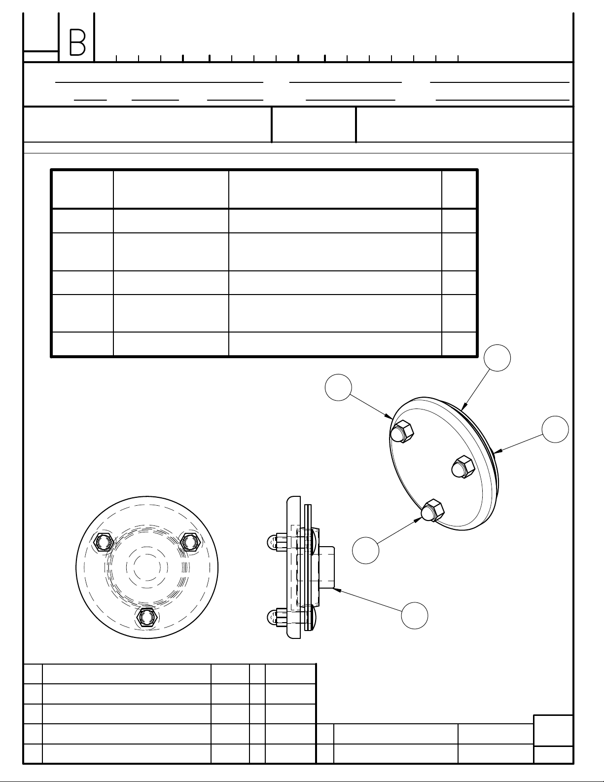
0860-0070
CHANGE
204 BEARING ASSEMBLY W/ CAP SEE LIST
NAME
DRAWN BY DATE
SAT 5-3-16 1/2
SCALE
MAT'L
MAT'L NO.
FINISH
CUT SIZE
THIS DRAWING AND ALL PROPRIETARY RIGHTS AND CONCEPTS HEREIN ARE
THE EXCLUSIVE PROPERTY OF OLIVER PACKAGING AND EQUIPMENT COMPANY AND ARE NOT
TO BE USED, DUPLICATED OR TREATED IN ANY WAY INCONSISTANT WITH
SUCH RIGHTS WITHOUT PERMISSION OF OLIVER PACKAGING & EQU IPMENT COMPANY.
DO NOT SCALE THIS DRAWING
Item
Part Number Description Qty
Number
1 5251-3945 BEARING, NTN AELPF204-012W3 1
2 5251-3945
CAP-BEARING AEL204 2
FLANGE
3 5500-4024 CAP-BEARING 204 1
4 5804-1731 BOLT, CARRIAGE 5/16-18 X 1
STST
5 5832-0584 NUT - ACORN 5/16-18 STST 3
REMOVE ALL BURRS
AND
SHARP EDGES
DIMENSIONAL TOLERANCES UNLESS SPECIFIED: FRACTIONAL ± 1/64; DECIMAL ± .005; ANGULAR ± 1°
OLIVER PACKAGING & EQUIPMENT CO.
WALKER, MICHIGAN, U.S.A. 49534-7564
3
2
3
4
5
1
LTR CHANGE DATE BY EC NO. 0 TOOL NAME NUMBER
MICRO
FILM
Page 18
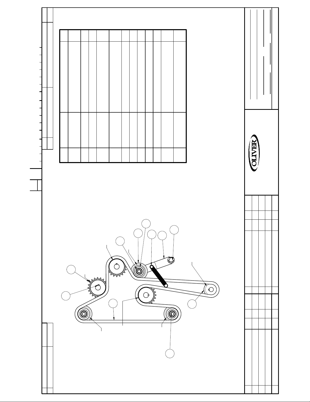
ITEM PART NUMBER DESCRIPTION QUAN.0 TOOL NAME NUMBER
Item Part Number Description Qty
0424 - 25003
C
1
1 0424-0018 WELDMENT, CHAIN TIGHTENER
1/4
1
1
1
1
DO NOT SCALE THIS DRAWING
FINISH
DATE SCALE
JCK 7-25-16
SEE LIST
ASSY, DRIVE CHAIN AND SPROCKETS
NAME
MAT'L
MAT'L NO.
DRAWN BY
DIMENSIONAL TOLERANCES UNLESS SPECIFIED: FRACTIONAL ± 1/64; DECIMAL ± .005; ANGULAR ± 1°
(IDLER) ARM
2 0424-0039 MODIFIED SPROCKET 1
AND COLLAR
STRAND 76" (152 LINKS)
3 0860-1251 IDLER SPROCKET ASSEMBLY 2
4 5251-3947 BEARING-AEL202 W/ .625 BORE
5 5603-4003 CHAIN-ROLLER #40 SINGLE
6 5616-9063 SPROCKET 40B14 3/4" MPB 1
7 5616-9121 SPROCKET-40B20 7/8" F.B. 3
8 5824-2319 KEY 3/16" SQ X 1" LG STST 4
9 5832-0506 NUT-HEX JAM 5/8-11NC FIN STST 1
LOCK
4.5L
10 5840-2842 RING - RETAINING 3/4" E-STYLE 1
12 7023-5101 SPRING-TENS 5/8 OD. X 0.063 X
11* 5851-9362 WASHER-STST 5/8" SPRING
REMOVE BURRS & SHARP EDGES
WALKER, MICHIGAN, U.S.A. 49534-7564
CHANGE
THIS DRAWING AND ALL PROPRIETARY RIGHTS AND CONCEPTS HEREIN ARE
THE EXCLUSIVE PROPERTY OF OLIVER PACKAGING AND EQUIPMENT COMPANY AND ARE NOT
TO BE USED, DUPLICATED OR TREATED IN ANY WAY INCONSISTANT WITH
SUCH RIGHTS WITHOUT PERMISSION OF OLIVER PACKAGING & EQUIPMENT COMPANY.
4
10
1
FIXED DOUGH ROLL
(20 TOOTH) SPROCKET
2
12
9
IDLER (16 TOOTH)
DRIVE SPROCKET
(14 TOOTH)
7
ADJUSTABLE DOUGH ROLL
(20 TOOTH ) SPROCKET
LTR EC NO.BYDATECHANGE
8
5
6
IDLER (16 TOOTH)
COVEYOR DRIVE ROLL
(20 TOOTH)
3
IDLER (16 TOOTH)
LTR CHANGE DATE BY EC NO.
Page 19
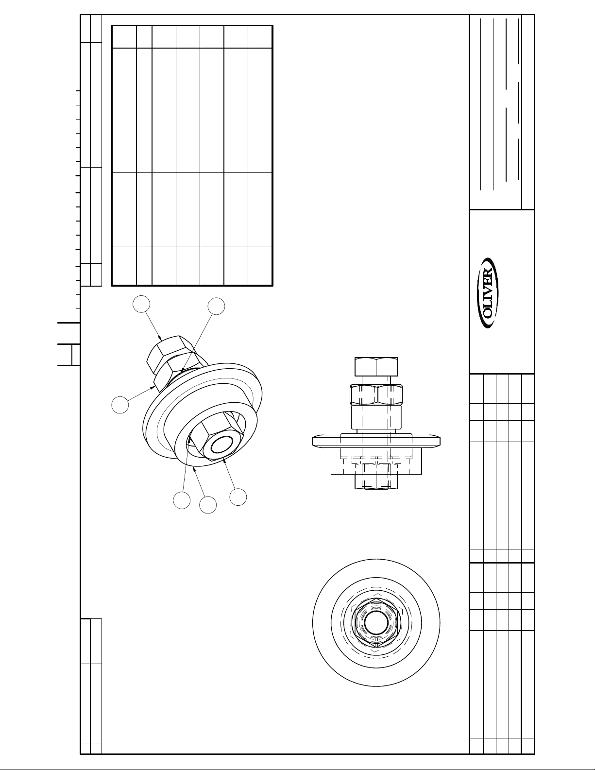
1
1
1
1
1
1:1
DO NOT SCALE THIS DRAWING
FINISH
DATE SCALE
BORE AND COLLAR
STST
FIN
STST
LOCK
BW 6-16-16
5/8in (40B16) IDLER SPROCKET COMPLETE-ASSY
NAME
MAT'L
MAT'L NO.
DRAWN BY
DIMENSIONAL TOLERANCES UNLESS SPECIFIED: FRACTIONAL ± 1/64; DECIMAL ± .005; ANGULAR ± 1°
REMOVE BURRS & SHARP EDGES
Part Number Descr ipti on Qty
1 0860-0046 MODIFIED SPROCKET 1
2 5251-3947 BEARING-AEL202 W/ .625
3 5832-0507 NUT - HEX JAM 3/4-10NC FIN
4 5832-0526 NUT-HEX FULL 5/8-11NC STST
5 5843-1131 SCREW- HEX HD 5/8-11 X 2.5"
ITEM PART NUMBER DESCRIPTION QUAN.0 TOOL NAME NUMBER
Item
Number
6 5851-9362 WASHER-STST 5/8" SPRING
0860-1251
C
CHANGE
5
2
WALKER, MICHIGAN, U.S.A. 49534-7564
THIS DRAWING AND ALL PROPRIETARY RIGHTS AND CONCEPTS HEREIN ARE
THE EXCLUSIVE PROPERTY OF OLIVER PACKAGING AND EQUIPMENT COMPANY AND ARE NOT
TO BE USED, DUPLICATED OR TREATED IN ANY WAY INCONSISTANT WITH
SUCH RIGHTS WITHOUT PERMISSION OF OLIVER PACKAGING & EQUIPMENT COMPANY.
3
6
1
4
LTR EC NO.BYDATECHANGE
LTR CHANGE DATE BY EC NO.
Page 20
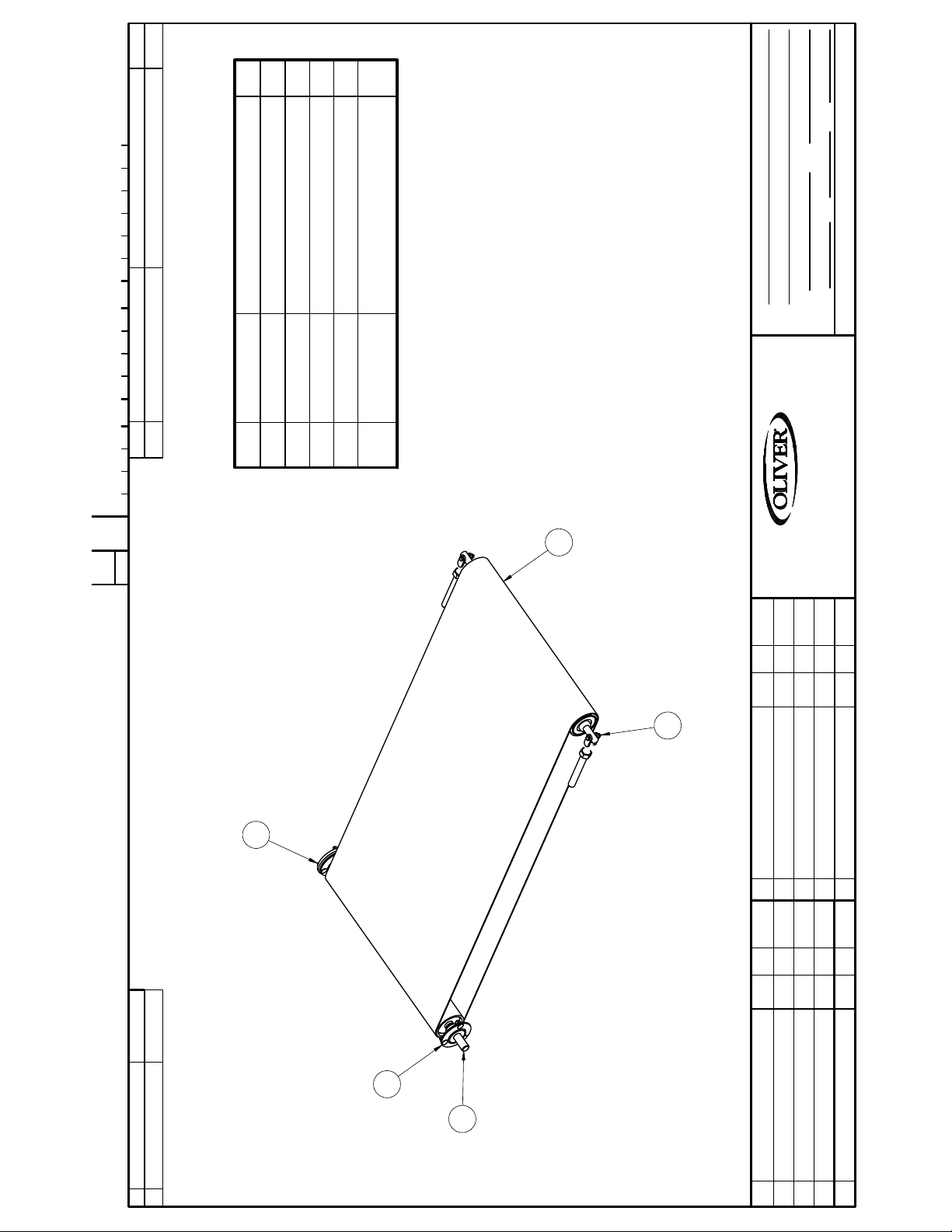
1
1/8
DO NOT SCALE THIS DRAWING
FINISH
DATE SCALE
JCK 7-25-16
SEE LIST
110
ASSY CONVEYOR BELT AND ROLLERS
NAME
MAT'L
MAT'L NO.
DRAWN BY
DIMENSIONAL TOLERANCES UNLESS SPECIFIED: FRACTIONAL ± 1/64; DECIMAL ± .005; ANGULAR ± 1°
REMOVE BURRS & SHARP EDGES
ITEM PART NUMBER DESCRIPTION QUAN.0 TOOL NAME NUMBER
0424 - 25004
C
CHANGE
Item Part Number Description Qty
1 0860-0049 24in x 3.5in DRIVE ROLLER ASSY 1
2 0860-0064 IDLE BELT ROLLER ASSEMBLY 1
3 0860-0072 BEARING ASSY OUTSIDE .875 1
4 0860-1197 BEARING ASSY .875 1
5 5601-4222 BELT, SIMPLEX CONVEYOR 24 X
WALKER, MICHIGAN, U.S.A. 49534-7564
5
THIS DRAWING AND ALL PROPRIETARY RIGHTS AND CONCEPTS HEREIN ARE
THE EXCLUSIVE PROPERTY OF OLIVER PACKAGING AND EQUIPMENT COMPANY AND ARE NOT
TO BE USED, DUPLICATED OR TREATED IN ANY WAY INCONSISTANT WITH
SUCH RIGHTS WITHOUT PERMISSION OF OLIVER PACKAGING & EQUIPMENT COMPANY.
2
3
LTR EC NO.BYDATECHANGE
4
1
LTR CHANGE DATE BY EC NO.
Page 21
ITEM PART NUMBER DESCRIPTION QUAN.0 TOOL NAME NUMBER
0860-0064
C
1:4
DO NOT SCALE THIS DRAWING
FINISH
DATE SCALE
WHW 3-2-16
SEE CHART
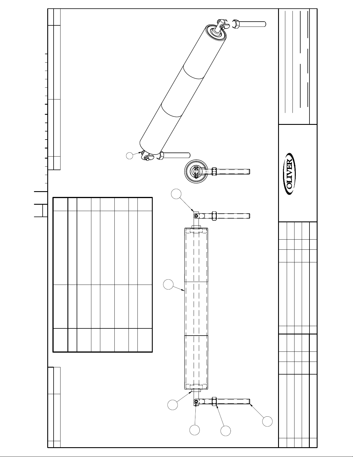
24in X 3.5in IDLE ROLLER COMPLETE ASSEMBLY
NAME
MAT'L
MAT'L NO.
DRAWN BY
DIMENSIONAL TOLERANCES UNLESS SPECIFIED: FRACTIONAL ± 1/64; DECIMAL ± .005; ANGULAR ± 1°
REMOVE BURRS & SHARP EDGES
1
2
1
2
2
2
WALKER, MICHIGAN, U.S.A. 49534-7564
CHANGE
Part Number Descr iption Qty
Item
Number
1 0860-0009 WELDMENT-FORK 2
SHAFT
2 0860-0011 COMMON IDLE ROLLER
THIS DRAWING AND ALL PROPRIETARY RIGHTS AND CONCEPTS HEREIN ARE
THE EXCLUSIVE PROPERTY OF OLIVER PACKAGING AND EQUIPMENT COMPANY AND ARE NOT
TO BE USED, DUPLICATED OR TREATED IN ANY WAY INCONSISTANT WITH
SUCH RIGHTS WITHOUT PERMISSION OF OLIVER PACKAGING & EQUIPMENT COMPANY.
BEARING W/ LOCKING SET
STST
3 0860-0048 24" IDLER BELT ROLLER 1
4 5251-3948 NTN ASS204-012N 3/4"
5 5832-0527 NUT - HEX FULL 3/4-10NC FIN
STST
6 5832-0590 NUT-ACORN 1/4-20 2
7 5843-1007 SCREW- HEX HD 1/4-20 X 1-1/2
3
LTR EC NO.BYDATECHANGE
4
1
6
5
LTR CHANGE DATE BY EC NO.
Page 22
0860-0072
CHANGE
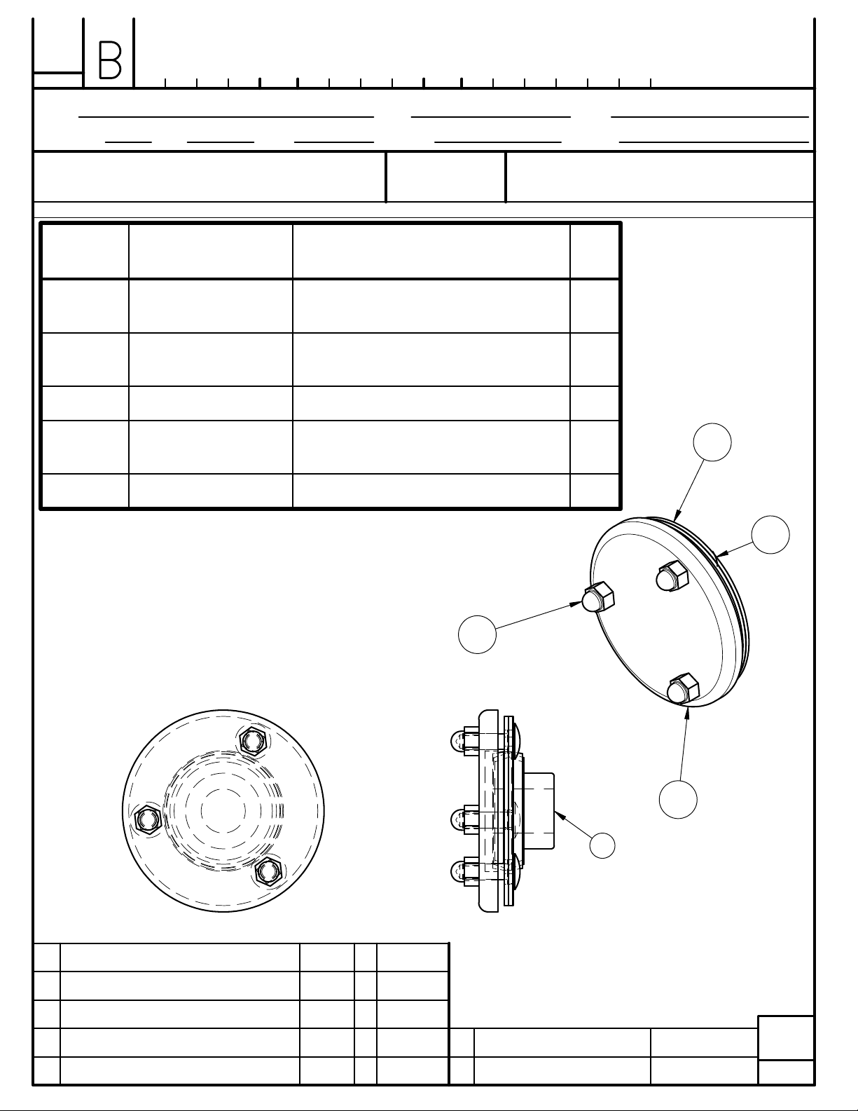
BEARING ASSY OUTSIDE .875 SEE CHART
NAME
DRAWN BY DATE
WHW
3-3-16 1:2
SCALE
MAT'L
MAT'L NO.
FINISH
CUT SIZE
THIS DRAWING AND ALL PROPRIETARY RIGHTS AND CONCEPTS HEREIN ARE
THE EXCLUSIVE PROPERTY OF OLIVER PACKAGING AND EQUIPMENT COMPANY AND ARE NOT
TO BE USED, DUPLICATED OR TREATED IN ANY WAY INCONSISTANT WITH
SUCH RIGHTS WITHOUT PERMISSION OF OLIVER PACKAGING & EQU IPMENT COMPANY.
DO NOT SCALE THIS DRAWING
Item
Part Number Description Qty
REMOVE ALL BURRS
AND
SHARP EDGES
DIMENSIONAL TOLERANCES UNLESS SPECIFIED: FRACTIONAL ± 1/64; DECIMAL ± .005; ANGULAR ± 1°
Number
1 5251-3946 NTN BEARING
AELPF205-014W3
2 5251-3946
BEARING FLA NG E NTN PF-205 2
FLANGE
3 5500-4023 COVER, BEARING 205 1
4 5804-1731 BOLT, CARRIAGE 5/16-18 X 1
STST
5 5832-0584 NUT - ACORN 5/16-18 STST 3
OLIVER PACKAGING & EQUIPMENT CO.
WALKER, MICHIGAN, U.S.A. 49534-7564
1
3
2
4
4
3
1
LTR CHANGE DATE BY EC NO. 0 TOOL NAME NUMBER
MICRO
FILM
Page 23
24
17
18
15
1/4
DO NOT SCALE THIS DRAWING
0424 - 25005 SHT 1 OF 2
C
CHANGE
27
4
FINISH
3
13
4
DATE SCALE
11
12
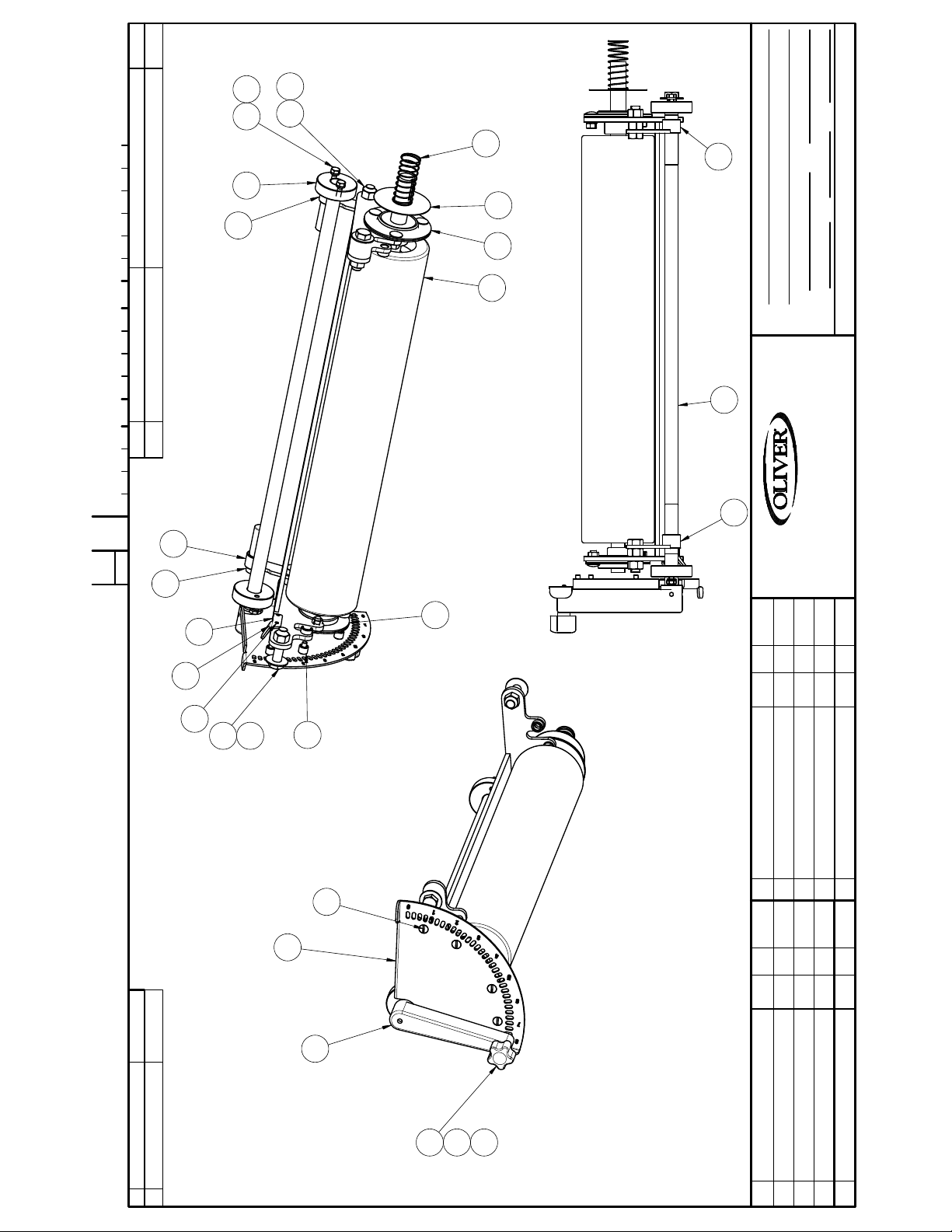
ASSY- ADJ. DOUGH ROLL
NAME
JCK 7-26-16
SEE LIST
MAT'L
MAT'L NO.
DRAWN BY
REMOVE BURRS & SHARP EDGES
DIMENSIONAL TOLERANCES UNLESS SPECIFIED: FRACTIONAL ± 1/64; DECIMAL ± .005; ANGULAR ± 1°
2
ITEM PART NUMBER DESCRIPTION QUAN.0 TOOL NAME NUMBER
5
WALKER, MICHIGAN, U.S.A. 49534-7564
5
2
THIS DRAWING AND ALL PROPRIETARY RIGHTS AND CONCEPTS HEREIN ARE
THE EXCLUSIVE PROPERTY OF OLIVER PACKAGING AND EQUIPMENT COMPANY AND ARE NOT
TO BE USED, DUPLICATED OR TREATED IN ANY WAY INCONSISTANT WITH
SUCH RIGHTS WITHOUT PERMISSION OF OLIVER PACKAGING & EQUIPMENT COMPANY.
10
20
1
192122
14
9
LTR EC NO.BYDATECHANGE
6
7
25
16
26
LTR CHANGE DATE BY EC NO.
Page 24
FINISH
1/4
DATE SCALE
DO NOT SCALE THIS DRAWING
0424 - 25005 SHT 2 OF 2
C
CHANGE
4
2
2
2
2
4
1
1
1
JCK 7-26-16
SEE LIST
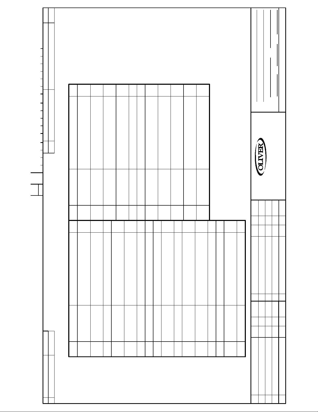
ASSY- ADJ. DOUGH ROLL
NAME
MAT'L
MAT'L NO.
DRAWN BY
DIMENSIONAL TOLERANCES UNLESS SPECIFIED: FRACTIONAL ± 1/64; DECIMAL ± .005; ANGULAR ± 1°
REMOVE BURRS & SHARP EDGES
ITEM PART NUMBER DESCRIPTION QUAN.0 TOOL NAME NUMBER
LOCK
SPRING
1 1/2 O.D. W/ 1/4-20 INSERT
2.00L
.045WD X 2.75L
WALKER, MICHIGAN, U.S.A. 49534-7564
THIS DRAWING AND ALL PROPRIETARY RIGHTS AND CONCEPTS HEREIN ARE
THE EXCLUSIVE PROPERTY OF OLIVER PACKAGING AND EQUIPMENT COMPANY AND ARE NOT
TO BE USED, DUPLICATED OR TREATED IN ANY WAY INCONSISTANT WITH
SUCH RIGHTS WITHOUT PERMISSION OF OLIVER PACKAGING & EQUIPMENT COMPANY.
22 5851-9308 WASHER - 1/2" FLAT 18-8 STST 2
24 5851-9357 WASHER- LOCK 1/4 STST
25 5911-7056 KNOB, POLY PROPYLENE 5 LOBE
26 7012-3011 SPRING, 5/16 O.D. X 0.029 WIRE X
23* 5851-9355 WASHER - #10 STST SPRING
4
27 7015-4202 SPRING-COMP 1.095OD X
1
1
4
Item Part Number Description Qty
17 5843-1003 SCREW- HEX HD 1/4-20 X 3/4
1
STST
STST
18 5843-1104 SCREW- HEX HD 1/2-13 X 1-1/2
1
19 5843-1106 SCREW- HEX HD 1/2-13 X 2"
STST
1
20 5843-1232 SCREW-HEX HD #10-24 X 1/2,
STST
21 5843-5083 SCREW-FLAT HEAD 1/4-20 X 3/4 4
1
Item Part Number Description Qty
1 0424-0005 WELDMENT, 4-24 ADJ. ROLL
FLANGES
HOLDER
CONTROL BAR
2 0424-0006 WELDMENT, 4-24 ROLL
3 0424-0007 BUSHING, ROLL CONTROL PIVOT 2
L.H.
4 0424-0008-0001 WLDMNT- CONTROL PIVOT LINK
R.H.
5 0424-0008-0002 WLDMNT- CONTROL PIVOT LINK
.42
6 0424-0009 PLATE, ROLLER INDEX 6 3/4 1
7 0424-0010 INDEX HANDLE 1
9 0424-0012 STANDOFF, 1/2 O.D. X 1/4 I.D. X
8* 0424-0011 PIN, 4-24 INDEX 1
10 0424-0017 CATCH, SPRING 1
11 0424-1190 BEARING ASSY .875in WITH
ASSEMBLY
12 0860-0003 ADJUSTABLE DOUGH ROLLER
13 0860-0019 GUARD-SPLASH 1
STST
14 0860-1196 BEARING ASSY .750in 1
15 5832-0524 NUT - HEX FULL 1/2-13NC FIN
16 5835-6220 DOWEL PIN, 3/16 X 1/2 1
LTR EC NO.BYDATECHANGE
LTR CHANGE DATE BY EC NO.
Page 25
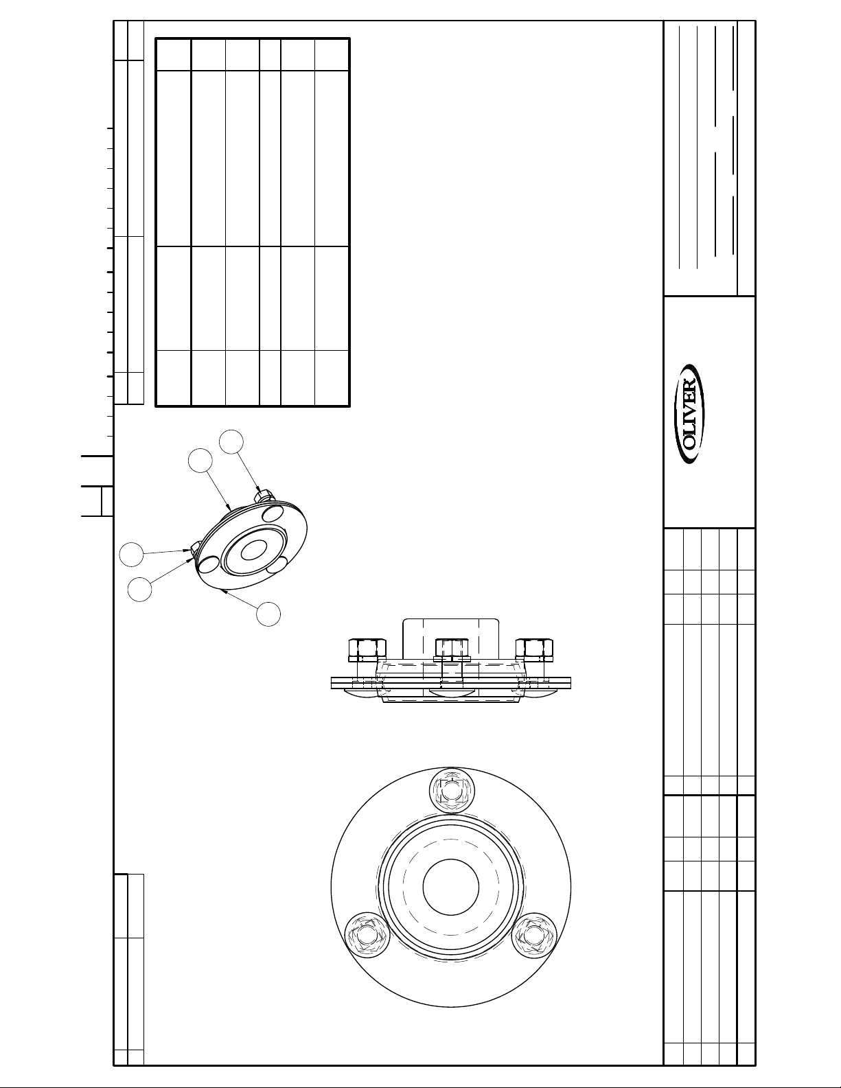
1
AELPF205-014W3
BEARING FLANGE NTN PF-205 2
3
STST
3
1:1
DO NOT SCALE THIS DRAWING
FINISH
DATE SCALE
18-8
BEARING ASSY .875in
NAME
WHW 6-17-16
SEE CHART
MAT'L
MAT'L NO.
DRAWN BY
DIMENSIONAL TOLERANCES UNLESS SPECIFIED: FRACTIONAL ± 1/64; DECIMAL ± .005; ANGULAR ± 1°
REMOVE BURRS & SHARP EDGES
Part Number Description Qty
FLANGE
1 5251-3946 NTN BEARING
2 5251-3946
3 5804-1730 BOLT, CARRIAGE 5/16-18 X .75 3
4 5832-0521 NUT- HEX FULL 5/16-18NC FIN
ITEM PART NUMBER DESCRIPTION QUAN.0 TOOL NAME NUMBER
Item
Number
5 5851-9358 WASHER-LOCK 5/16" STST
0424 - 1190
C
CHANGE
4
5
3
1
WALKER, MICHIGAN, U.S.A. 49534-7564
THIS DRAWING AND ALL PROPRIETARY RIGHTS AND CONCEPTS HEREIN ARE
THE EXCLUSIVE PROPERTY OF OLIVER PACKAGING AND EQUIPMENT COMPANY AND ARE NOT
TO BE USED, DUPLICATED OR TREATED IN ANY WAY INCONSISTANT WITH
SUCH RIGHTS WITHOUT PERMISSION OF OLIVER PACKAGING & EQUIPMENT COMPANY.
2
LTR EC NO.BYDATECHANGE
LTR CHANGE DATE BY EC NO.
Page 26
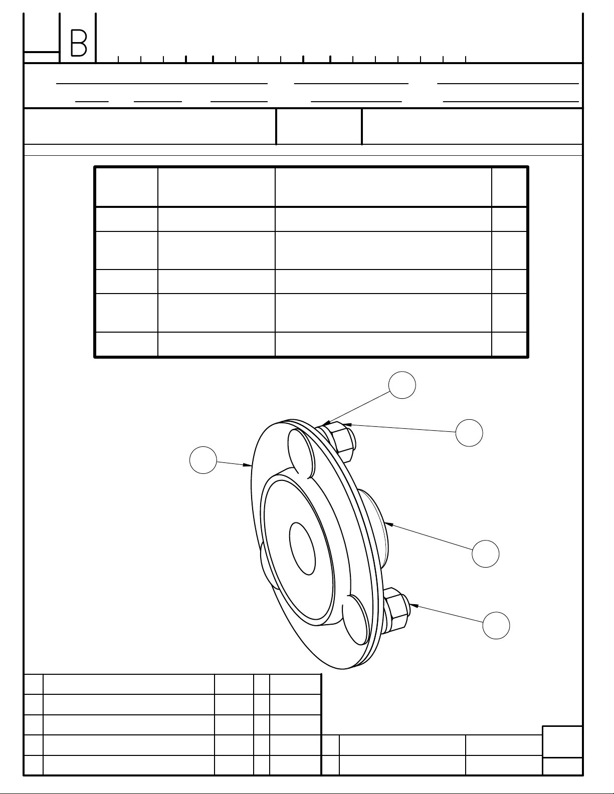
0860-1196
CHANGE
204 BEARING ASSEMBLY SEE LIST
NAME
DRAWN BY DATE
SAT 5-3-16 FULL
SCALE
MAT'L
MAT'L NO.
FINISH
CUT SIZE
THIS DRAWING AND ALL PROPRIETARY RIGHTS AND CONCEPTS HEREIN ARE
THE EXCLUSIVE PROPERTY OF OLIVER PACKAGING AND EQUIPMENT COMPANY AND ARE NOT
TO BE USED, DUPLICATED OR TREATED IN ANY WAY INCONSISTANT WITH
SUCH RIGHTS WITHOUT PERMISSION OF OLIVER PACKAGING & EQU IPMENT COMPANY.
DO NOT SCALE THIS DRAWING
Item
Part Number Description Qty
Number
1 5251-3945 BEARING, NTN AELPF204-012W3 1
2 5251-3945
FLANGE
3 5804-1730 BOLT, CARRIAGE 5/16-18 X .75 3
4 5832-0521 NUT- HEX FULL 5/16-18NC FIN
5 5851-9358 WASHER-LOCK 5/16" STST 18-8 3
REMOVE ALL BURRS
AND
SHARP EDGES
DIMENSIONAL TOLERANCES UNLESS SPECIFIED: FRACTIONAL ± 1/64; DECIMAL ± .005; ANGULAR ± 1°
OLIVER PACKAGING & EQUIPMENT CO.
WALKER, MICHIGAN, U.S.A. 49534-7564
CAP-BEARING AEL204 2
3
STST
5
4
2
1
3
LTR CHANGE DATE BY EC NO. 0 TOOL NAME NUMBER
MICRO
FILM
Page 27
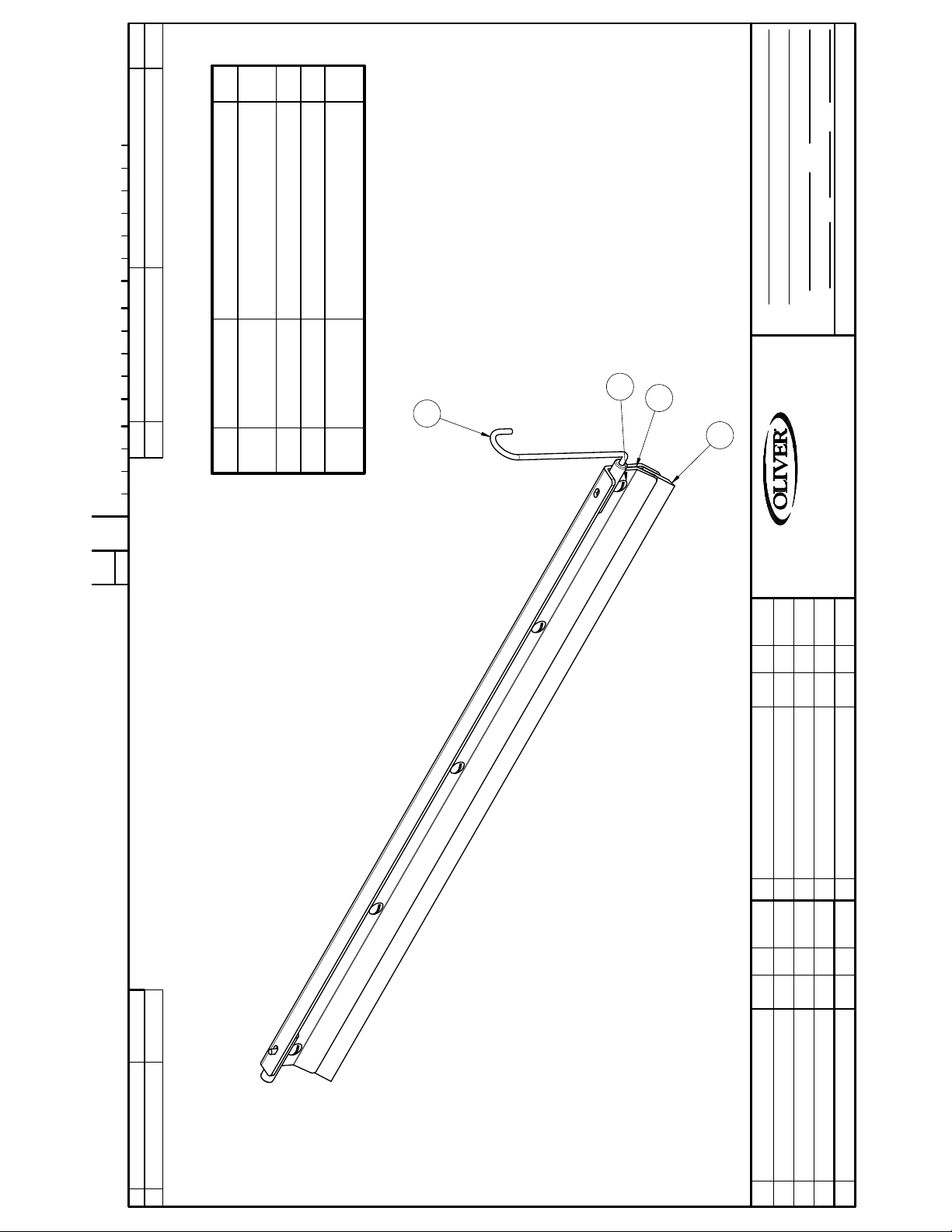
BLOEMHOF 1308
ITEM PART NUMBER DESCRIPTION QUAN.0 TOOL NAME NUMBER
0424 - 25006
C
Item Part Number Description Qty
1
4-24 REAR
1 0424-0015 WELDMENT- 23 1/4" SCRAPER
5
1/2
DO NOT SCALE THIS DRAWING
FINISH
DATE SCALE
JCK 07-08-16
SEE LIST
STST
4
2
SCRAPER, 4-24 23 1/4" (REAR)
NAME
MAT'L
MAT'L NO.
DRAWN BY
DIMENSIONAL TOLERANCES UNLESS SPECIFIED: FRACTIONAL ± 1/64; DECIMAL ± .005; ANGULAR ± 1°
REMOVE BURRS & SHARP EDGES
1
3
2 0424-0016 CLAMP, SCRAPER BLADE 23 1/4" 1
3 5500-2950 BLADE-SCRAPER 860L 1
4 5843-5383 SCREW-TRUSS HEAD 10-24 x 1/4
WALKER, MICHIGAN, U.S.A. 49534-7564
CHANGE
THIS DRAWING AND ALL PROPRIETARY RIGHTS AND CONCEPTS HEREIN ARE
THE EXCLUSIVE PROPERTY OF OLIVER PACKAGING AND EQUIPMENT COMPANY AND ARE NOT
TO BE USED, DUPLICATED OR TREATED IN ANY WAY INCONSISTANT WITH
SUCH RIGHTS WITHOUT PERMISSION OF OLIVER PACKAGING & EQUIPMENT COMPANY.
LTR EC NO.BYDATECHANGE
LTR CHANGE DATE BY EC NO.
Page 28
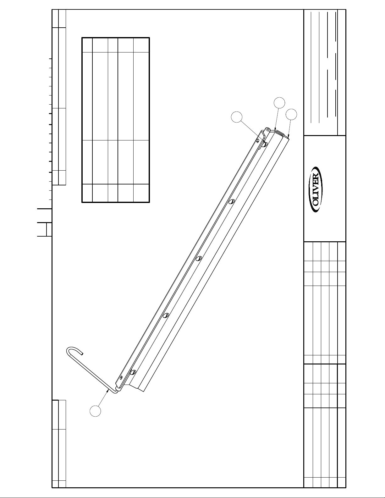
BLOEMHOF 1307
1/2
1
1
5
DO NOT SCALE THIS DRAWING
FINISH
DATE SCALE
2
ITEM PART NUMBER DESCRIPTION QUAN.0 TOOL NAME NUMBER
Item Part Number Description Qty
0424 - 25007
C
CHANGE
4-24 FRONT
1 0424-0013 WELDMENT, 24 3/8" SCRAPER
4
FRONT
STST
2 0424-0014 CLAMP, SCRAPER BLADE 24 3/8" 1
3 5500-2951 BLADE-24 3/8" SCRAPER 4-24
4 5843-5383 SCREW-TRUSS HEAD 10-24 x 1/4
3
SCRAPER, 4-24 FRONT (24 3/8)
NAME
JCK 07-08-16
SEE LIST
MAT'L
MAT'L NO.
DRAWN BY
WALKER, MICHIGAN, U.S.A. 49534-7564
THIS DRAWING AND ALL PROPRIETARY RIGHTS AND CONCEPTS HEREIN ARE
REMOVE BURRS & SHARP EDGES
THE EXCLUSIVE PROPERTY OF OLIVER PACKAGING AND EQUIPMENT COMPANY AND ARE NOT
TO BE USED, DUPLICATED OR TREATED IN ANY WAY INCONSISTANT WITH
SUCH RIGHTS WITHOUT PERMISSION OF OLIVER PACKAGING & EQUIPMENT COMPANY.
DIMENSIONAL TOLERANCES UNLESS SPECIFIED: FRACTIONAL ± 1/64; DECIMAL ± .005; ANGULAR ± 1°
LTR EC NO.BYDATECHANGE
1
LTR CHANGE DATE BY EC NO.
Page 29
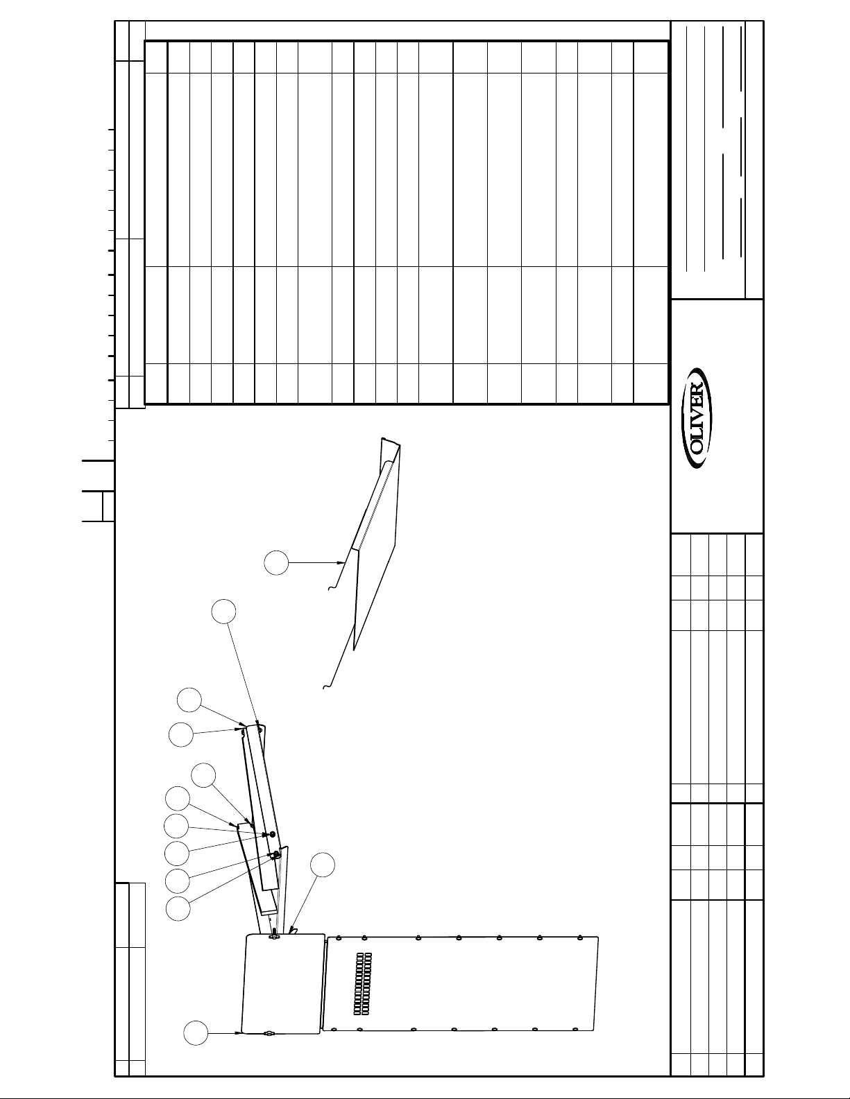
1 0424-0017 CATCH, SPRING 1
Item Part Number Description Qty
ITEM PART NUMBER DESCRIPTION QUAN.0 TOOL NAME NUMBER
0424 - 25013
C
2
STST
2 0424-0035 PAN, INFEED 1
3 0424-0036 BAR, INFEED ARM 2
4 0424-0037 WELDMENT- OUTFEED TRAY 1
5 0424-0040 WELDMENT, REAR COVER 1
6 5832-0500 NUT-HEX 1/4, JAM, STST 2
7 5832-0521 NUT- HEX FULL 5/16-18NC FIN
9 5832-0590 NUT-ACORN 1/4-20 2
8* 5832-0584 NUT - ACORN 5/16-18 STST 2
11 5843-1009 SCREW- HEX HD 1/4-20 X 2 STST 2
10* 5835-6471 PIN-DOWEL 3/16 X 1 2
2
12* 5843-1027 SCREW- HEX HD 5/16-18 X 5/8
STST
2
13 5843-1028 SCREW- HEX HD 5/16-18 X 3/4
STST
2
14* 5843-1231 SCREW-HEX HD #10-24 X 3/8,
STST
16
3/8 STST
15* 5843-5411 SCREW-TRUSS HD SLTD 1/4-20 X
2
LOCK
16 5851-9305 WASHER - FLAT 5/16" 18-8 STST 4
17* 5851-9355 WASHER - #10 STST SPRING
2
1/8
DO NOT SCALE THIS DRAWING
FINISH
DATE SCALE
JCK 7-26-16
ASSY. COVERS AND TRAYS
NAME
SEE LIST
MAT'L
MAT'L NO.
DRAWN BY
WALKER, MICHIGAN, U.S.A. 49534-7564
REMOVE BURRS & SHARP EDGES
DIMENSIONAL TOLERANCES UNLESS SPECIFIED: FRACTIONAL ± 1/64; DECIMAL ± .005; ANGULAR ± 1°
STUD
18 5851-9358 WASHER-LOCK 5/16" STST 18-8 4
19* 5911-7125 KNOB-2 PRONG, W/1/4-20X1
CHANGE
11
7
18
13
16
THIS DRAWING AND ALL PROPRIETARY RIGHTS AND CONCEPTS HEREIN ARE
THE EXCLUSIVE PROPERTY OF OLIVER PACKAGING AND EQUIPMENT COMPANY AND ARE NOT
TO BE USED, DUPLICATED OR TREATED IN ANY WAY INCONSISTANT WITH
SUCH RIGHTS WITHOUT PERMISSION OF OLIVER PACKAGING & EQUIPMENT COMPANY.
4
9
2
3
6
LTR EC NO.BYDATECHANGE
1
5
LTR CHANGE DATE BY EC NO.
Page 30
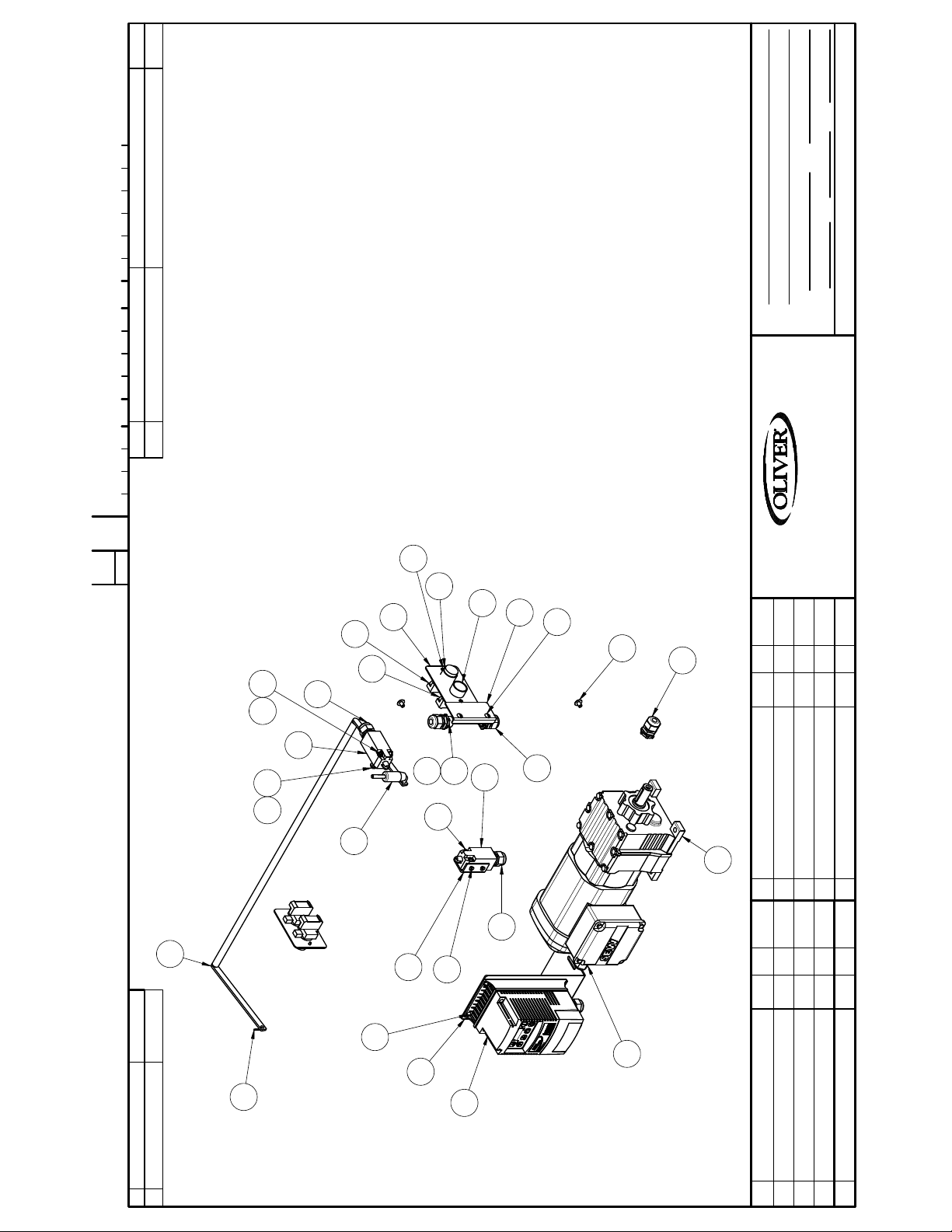
0424 - 25020 SHT 1 OF 2
C
CHANGE
3/16
DO NOT SCALE THIS DRAWING
FINISH
DATE SCALE
JCK 7-26-16
SEE LIST
ASSY- ELECTRICAL COMPONENTS
NAME
MAT'L
MAT'L NO.
DRAWN BY
DIMENSIONAL TOLERANCES UNLESS SPECIFIED: FRACTIONAL ± 1/64; DECIMAL ± .005; ANGULAR ± 1°
REMOVE BURRS & SHARP EDGES
ITEM PART NUMBER DESCRIPTION QUAN.0 TOOL NAME NUMBER
WALKER, MICHIGAN, U.S.A. 49534-7564
19
THIS DRAWING AND ALL PROPRIETARY RIGHTS AND CONCEPTS HEREIN ARE
THE EXCLUSIVE PROPERTY OF OLIVER PACKAGING AND EQUIPMENT COMPANY AND ARE NOT
TO BE USED, DUPLICATED OR TREATED IN ANY WAY INCONSISTANT WITH
SUCH RIGHTS WITHOUT PERMISSION OF OLIVER PACKAGING & EQUIPMENT COMPANY.
1625
12
10
8
7
3
9
5
22
23
14
11
14
24 18
12
29
15
11
2
27
LTR EC NO.BYDATECHANGE
12
1
6
20
21
13
4
17
26
LTR CHANGE DATE BY EC NO.
Page 31
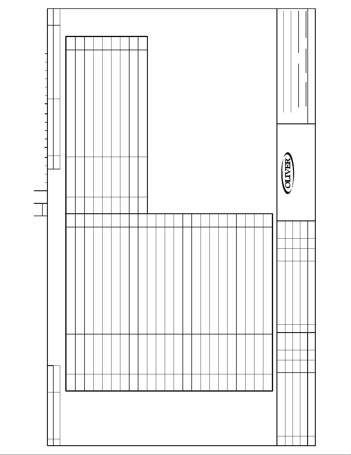
0424 - 25020 SHT 2 OF 2
C
CHANGE
3/16
DO NOT SCALE THIS DRAWING
FINISH
DATE SCALE
JCK 7-26-16
SEE LIST
ASSY- ELECTRICAL COMPONENTS
NAME
MAT'L
MAT'L NO.
DRAWN BY
DIMENSIONAL TOLERANCES UNLESS SPECIFIED: FRACTIONAL ± 1/64; DECIMAL ± .005; ANGULAR ± 1°
REMOVE BURRS & SHARP EDGES
ITEM PART NUMBER DESCRIPTION QUAN.0 TOOL NAME NUMBER
WALKER, MICHIGAN, U.S.A. 49534-7564
MOTOR CORD PN 0860-0039
16 GA. 3 COND. POWER CORD W/ GROUNDED PLUG 5765-8300
23 5843-5411 SCREW-TRUSS HD SLTD 1/4-20 X 3/8 STST 2
24 5851-9302 WASHER - FLAT No.10, 18-8 STST 2
25 5851-9394 WASHER- #10 STST INT TOOTH LOCK 2
26 6309-1465 DRIVE-1HP VFD 115/230 1PH LENZE 1
Item Part Number Description Qty
27 6310-0500 GEARMOTOR .75 HP, 167RPM SEW 1
29 8843-2277 SCREW-STST SLOTTED PAN HD M4 X 30MM 2
28* 8832-0011 NUT-HEX HD STST M4 DIN 934 2
30* 8851-9861 WASHER-STST INT TOOTH M4 2
THIS DRAWING AND ALL PROPRIETARY RIGHTS AND CONCEPTS HEREIN ARE
THE EXCLUSIVE PROPERTY OF OLIVER PACKAGING AND EQUIPMENT COMPANY AND ARE NOT
TO BE USED, DUPLICATED OR TREATED IN ANY WAY INCONSISTANT WITH
SUCH RIGHTS WITHOUT PERMISSION OF OLIVER PACKAGING & EQUIPMENT COMPANY.
Item Part Number Description Qty
LTR EC NO.BYDATECHANGE
1 0424-0019 WELDMENT, SAFETY BAR 1
2 0424-0024 BUSHING, SAFETY BAR 1
3 0424-0038 COVER- SWITCH BOX 2
4 0424-0041 DRIVE MOUNTING PLATE 1
5 0424-0042 COVER, JUNCTION BOX 1
6 0860-0084 BRACKET SWITCH 1
7 5708-7900 OPERATOR-PB GREEN FLUSH 2
8 5708-7908 OPERATOR-PUSHBUTTON RED EXTENDED 2
9 5708-7930 BASE-MTG/BLOCK-CONTACT NO 2
10 5708-7931 BASE-MTG/BLOCK-CONTACT NC 2
11 5757-7360 SP DT LIMIT SWITCH 10AMP 2
12 5765-1082 RELIEF-STRAIN 1/2NPT 5
13 5765-1120 STRAIN RELIEF M20 X 1.5 2
14 5765-1121 STRAIN RELIEF M20 X 1.5 2
15 5766-7750 NUT-LOCK APPLETON # BL-50 4
16 5832-0407 NUT-HEX ---10-24 STST 2
17 5835-6401 PIN-COTTER 1/16 DIA X 3/4 STST 1
18 5843--1238 SCREW-HEX HD #10-24 X 1-1/2 2
19 5843-5040 SCREW-STST FLAT HD #6-32 X 1/4 4
20 5843-5065 SCREW- FLAT HD 10-24 X 1/4 2
21 5843-5301 SCREW-STST ROUND HD 10-32 X 3/8 4
22 5843-5384 SCREW-TRUSS HEAD 10-24 x 3/8 STST 2
LTR CHANGE DATE BY EC NO.
Page 32
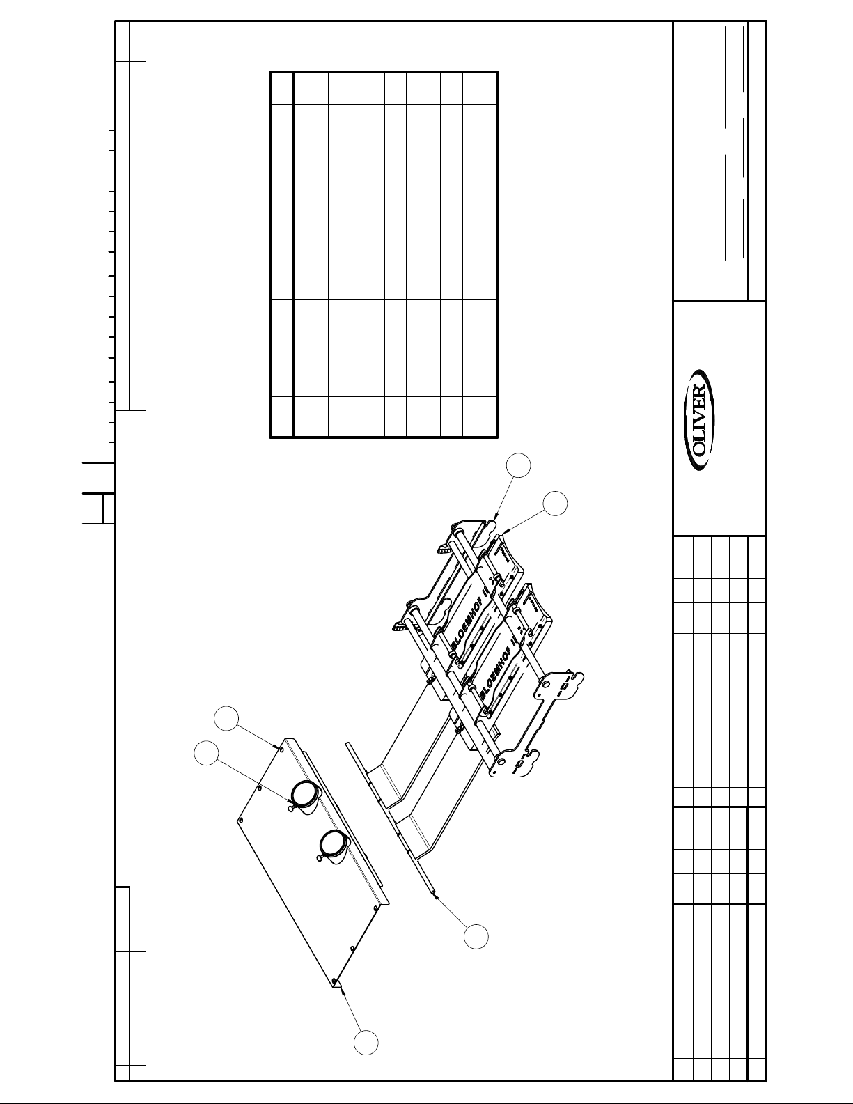
1
1
1
6
DO NOT SCALE THIS DRAWING
FINISH
DATE SCALE
SIMPLEX DUAL PPS PARTS
NAME
MAT'L
MAT'L NO.
TOP
ITEM PART NUMBER DESCRIPTION QUAN.0 TOOL NAME NUMBER
1 0424-0003-02 WELDMENT, 4-24 DOUBLE HOLE
Item Part Number Description Qty
CHAIN
2 0424-0004 TUBE, HOLE LINER 2
3 0424-0030-003 DUAL BOLILLO LIGHT CURLING
CLAMPS
4 0424-1130 ASSEMBLY, 6" BOLILLO PLATE 2
5 0424-25012 ASSEM BLY, DBL PPS FRAME W/
3/8 STST
7 5843-5411 SCREW-TRUSS HD SLTD 1/4-20 X
6* 5843-0538 SCREW-THUMB 1/4-20 X 1 2
DRAWN BY
DIMENSIONAL TOLERANCES UNLESS SPECIFIED: FRACTIONAL ± 1/64; DECIMAL ± .005; ANGULAR ± 1°
REMOVE BURRS & SHARP EDGES
0424 - 25022
C
CHANGE
5
WALKER, MICHIGAN, U.S.A. 49534-7564
4
THIS DRAWING AND ALL PROPRIETARY RIGHTS AND CONCEPTS HEREIN ARE
THE EXCLUSIVE PROPERTY OF OLIVER PACKAGING AND EQUIPMENT COMPANY AND ARE NOT
TO BE USED, DUPLICATED OR TREATED IN ANY WAY INCONSISTANT WITH
SUCH RIGHTS WITHOUT PERMISSION OF OLIVER PACKAGING & EQUIPMENT COMPANY.
7
2
LTR EC NO.BYDATECHANGE
3
1
LTR CHANGE DATE BY EC NO.
Page 33
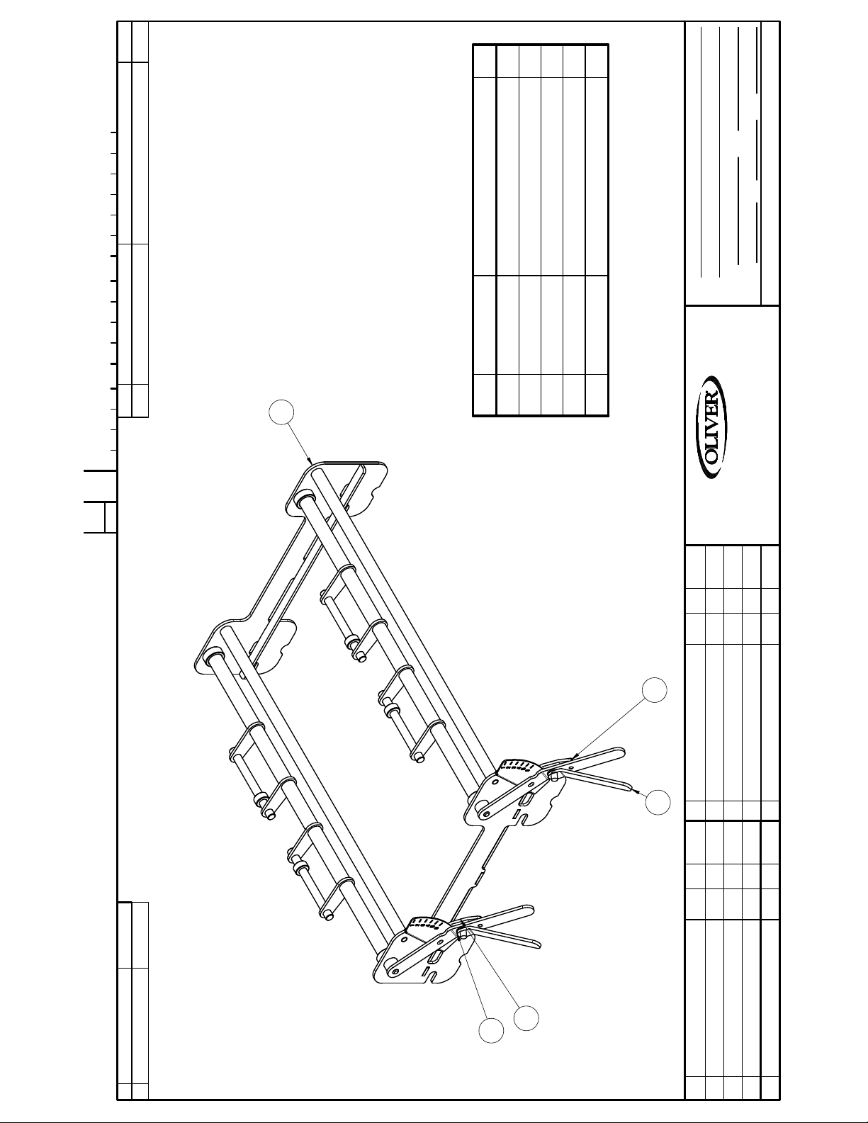
ITEM PART NUMBER DESCRIPTION QUAN.0 TOOL NAME NUMBER
0424 - 25012
C
1/4
DO NOT SCALE THIS DRAWING
FINISH
DATE SCALE
JCK 7-26-16
SEE LIST
ASSY, DBL PPS FRAME W/CLAMPLS
NAME
MAT'L
MAT'L NO.
DRAWN BY
DIMENSIONAL TOLERANCES UNLESS SPECIFIED: FRACTIONAL ± 1/64; DECIMAL ± .005; ANGULAR ± 1°
REMOVE BURRS & SHARP EDGES
1 0424-0020-02 WELDMENT, 4-24 PPS DBL 1
2 0424-0021 HANDLE 4-24 PPS CLAMP 2
3 0424-0022 SHOE, 4-24 PPS CLAMP 2
4 5804-0650 BOLT, CARRIAGE 3/8-16 x 1 1/4 2
1
Item Part Number Description Qty
5 5851-8404 WASHER-3/8 FLAT 2
WALKER, MICHIGAN, U.S.A. 49534-7564
CHANGE
THIS DRAWING AND ALL PROPRIETARY RIGHTS AND CONCEPTS HEREIN ARE
THE EXCLUSIVE PROPERTY OF OLIVER PACKAGING AND EQUIPMENT COMPANY AND ARE NOT
TO BE USED, DUPLICATED OR TREATED IN ANY WAY INCONSISTANT WITH
SUCH RIGHTS WITHOUT PERMISSION OF OLIVER PACKAGING & EQUIPMENT COMPANY.
3
2
LTR EC NO.BYDATECHANGE
4
5
LTR CHANGE DATE BY EC NO.
Page 34
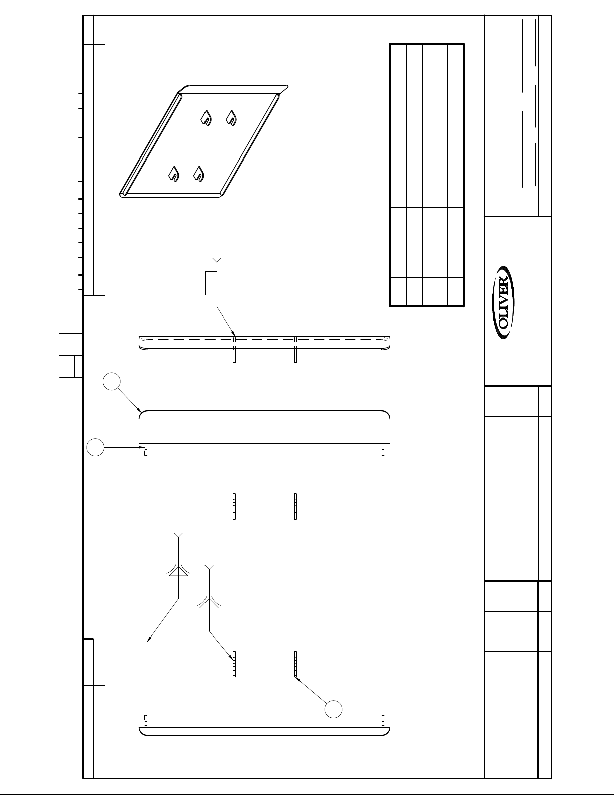
8 TABS
2
1/4
DO NOT SCALE THIS DRAWING
FABRIC COVERED
FINISH
DATE SCALE
JCK 6-27-16
SEE LIST, STST
SIDE
PLATE, 4-24 PPS WELDMENT 21 1/2"
NAME
MAT'L
MAT'L NO.
DRAWN BY
DIMENSIONAL TOLERANCES UNLESS SPECIFIED: FRACTIONAL ± 1/64; DECIMAL ± .005; ANGULAR ± 1°
REMOVE BURRS & SHARP EDGES
ITEM PART NUMBER DESCRIPTION QUAN.0 TOOL NAME NUMBER
0424 - 0026 - 086 SHT 1/2
C
CHANGE
1
2
TYP. STIFFENER
TYP. HOOK
1/8 1/2-2
Item Part Number Description Qty
1 0424-0025-086 PLATE, 4-24 PRESSURE 21.5 W 1
2 0424-0026-0013 STIFFENER, PPS SIMPLEX PLATE
3 0424-0026-0033 HOOK, PPS SIMPLEX 4
WALKER, MICHIGAN, U.S.A. 49534-7564
THIS DRAWING AND ALL PROPRIETARY RIGHTS AND CONCEPTS HEREIN ARE
THE EXCLUSIVE PROPERTY OF OLIVER PACKAGING AND EQUIPMENT COMPANY AND ARE NOT
TO BE USED, DUPLICATED OR TREATED IN ANY WAY INCONSISTANT WITH
SUCH RIGHTS WITHOUT PERMISSION OF OLIVER PACKAGING & EQUIPMENT COMPANY.
LTR EC NO.BYDATECHANGE
1/8 1/2-2
3
LTR CHANGE DATE BY EC NO.
Page 35
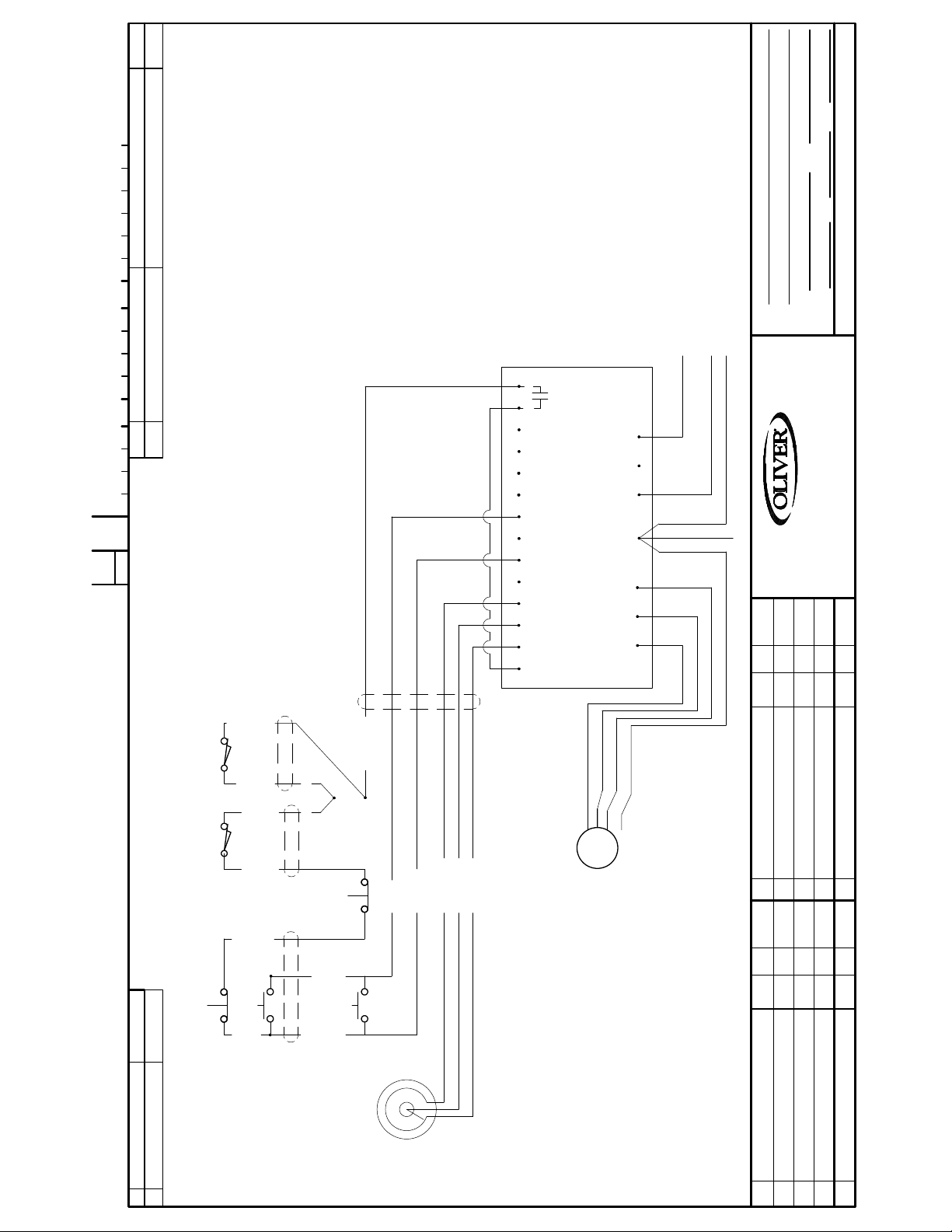
PARAMETERS
100: 1
101: 1
102: 30.0
104: 0.5
105: 0.5
108: 59
115: 1
121: 11
140: 3
110 V SINGLE PHASE
15 AMP
WALL PLUG
5765-8300
G
N
L1
BLACK
WHITE
GREEN
DO NOT SCALE THIS DRAWING
FINISH
DATE SCALE
JCK 8/18/16
424 SIMPLEX 1/60/115 ELECTRICS
NAME
MAT'L
MAT'L NO.
DRAWN BY
DIMENSIONAL TOLERANCES UNLESS SPECIFIED: FRACTIONAL ± 1/64; DECIMAL ± .005; ANGULAR ± 1°
REMOVE BURRS & SHARP EDGES
ITEM PART NUMBER DESCRIPTION QUAN.0 TOOL NAME NUMBER
0424 - C12001
C
CHANGE
REAR
COVER
BAR
SAFETY
LS1
LS1
14 30 16 17
13B 13C
VARIABLE
L1 L2 N
WALKER, MICHIGAN, U.S.A. 49534-7564
G
FREQUENCY DRIVE
25 4 11 13A
256
UVW
THIS DRAWING AND ALL PROPRIETARY RIGHTS AND CONCEPTS HEREIN ARE
THE EXCLUSIVE PROPERTY OF OLIVER PACKAGING AND EQUIPMENT COMPANY AND ARE NOT
TO BE USED, DUPLICATED OR TREATED IN ANY WAY INCONSISTANT WITH
SUCH RIGHTS WITHOUT PERMISSION OF OLIVER PACKAGING & EQUIPMENT COMPANY.
1
LEFT
STOP
3
3 ORANGE
RED (V)
BLACK (U)
WHITE (W)
G
M
MOTOR
2
3 BLACK
3 RED
1
3 BROWN
3 GREEN
3 YELLOW
3/4 HP GEAR
230 VOLT 3 PHASE
2 AMP
165 RPM
U1,V1,W1
CLOCKWISE ROT
FACING MOTOR
SHAFT END
VERIFY MOTOR TURNS
CLOCKWISE VIEWED AT
LTR EC NO.BYDATECHANGE
7
7 ORANGE
14
13
7 WHITE
5 WHITE
14
13
5 BLUE
5
4 VIOLET
4 RED
LEFT
4 BLACK
5 K POT
START
0-10 VDC SPEED
CONTROL
6309-6036
4
3
USED
USED
NOT USED
VFD LOW VOLTAGE TERMINALS
0 VDC
1. RUN
2.
5. 0-10 VDC SPEED SIGNAL
NOT
NOT
+15 VDC
11.
4.
6. +10VDC POWER SUPPLY
25.
13A. START FWD
13B. NOT USED
.
13C. NOT USED
14
NOT USED
.
30
16. INT. RELAY "FAULT"
17. INT. RELAY "FAULT"
LTR CHANGE DATE BY EC NO.
2
STOP
RIGHT
1
RIGHT
START
4
3
BLACK
4
Page 36

WARRANTY
PARTS
Oliver Packaging & Equipment Company warrants that if any part of the equipment (other than a
part not manufactured by Oliver) proves to be defective (as defined below) within one (1) year after
shipment, and if Buyer returns the defective part to Oliver Packaging & Equipment within one (1)
year, Freight Prepaid to Oliver Packaging & Equipment’s plant in Grand Rapids, MI, then Oliver
Packaging & Equipment, shall, at Oliver Packaging & Equipment’s option, either repair or replace the
defective part, at Oliver Packaging & Equipment’s expense.
LABOR
Oliver Packaging & Equipment further warrants that equipment properly installed in accordance with
our special instructions, which proves to be defective in material or workmanship under normal use
within one (1) year from installation or one (1) year from actual shipment date, whichever date
comes first, will be repaired by Oliver Packaging & Equipment or an Oliver Packaging & Equipment
Authorized Service Dealer, in accordance with Oliver Packaging & Equipment’s published Service
Schedule.
For purposes of this warranty, a defective part or defective equipment is a part or equipment which is
found by Oliver Packaging & Equipment to have been defective in materials workmanship, if the
defect materially impairs the value of the equipment to Buyer. Oliver Packaging & Equipment has no
obligation as to parts or components not manufactured by Oliver Packaging & Equipment, but Oliver
Packaging & Equipment assigns to Buyer any warranties made to Oliver Packaging & Equipment by
the manufacturer thereof.
This warranty does not apply to:
1. Damage caused by shipping or accident.
2. Damage resulting from improper installation or alteration.
3. Equipment misused, abused, altered, not maintained on a regular basis, operated carelessly, or
used in abnormal conditions.
4. Equipment used in conjunction with products of other manufacturers unless such use is approved
by Oliver Packaging & Equipment in writing.
5. Periodic maintenance of equipment, including but not limited to lubrication, replacement of wear
items, and other adjustments required due to installation, set up, or normal wear.
6. Losses or damage resulting from malfunction.
The foregoing warranty is in lieu of all other warranties expressed or implied AND OLIVER
PACKAGING & EQUIPMENT MAKES NO WARRANTY OF MERCHANTABILITY OR FITNESS FOR
PURPOSE REGARDING THE EQUIPMENT COVERED BY THIS WARRANTY. Oliver Packaging &
Equipment neither assumes nor authorizes any person to assume for it any other obligations or
liability in connection with said equipment. OLIVER PACKAGING & EQUIPMENT SHALL NOT BE
LIABLE FOR LOSS OF TIME, INCONVENIENCE, COMMERCIAL LOSS, INCIDENTAL OR
CONSEQUENTIAL DAMAGES.
GEN 040228
Page 37

WARRANTY PROCEDURE
1. If a problem should occur, either the dealer or the end user must contact the Parts and
Service Department and explain the problem.
2. The Parts and Service Manager will determine if the warranty will apply to this particular
problem.
3. If the Parts and Service Manager approves, a Work Authorization Number will be
generated, and the appropriate service agency will perform the service.
4. The service dealer will then complete an invoice and send it to the Parts and Service
Department at Oliver Packaging & Equipment Company.
The Parts and Service Manager of Oliv
5.
review the invoice and returned parts, if applicable, and approve for payment.
er Packaging and Equipment Company will
GEN
040226
Page 38

RETURNED PARTS POLICY
This policy applies
to all parts returned to the factory whether for warranted credit,
replacement, repair or re-stocking.
Oliver Packaging and Equipment Company requires that the customer obtain a Return
Material Authorization (RMA) number before returning any part. This number should appear
on the shipping label and inside the shipping carton as well. All parts are to be returned
prepaid. Following this procedure will insure prompt handling of all returned parts.
To obtain an RMA number contact the Repair Parts Department toll free at (800) 253-3893.
Parts returned for re-stocking are subject to a RE-STOCKING CHARGE.
Thank you for your cooperation,
Repair Parts Manager
Oliver Packaging and Equipment Company
GEN 040227
Page 39

 Loading...