


Grand Rapids, Michigan, U.S.A. 49504-5298
USER’S OPERATING AND INSTRUCTION MANUAL
MODELS 695 & 695D
PROOFERS
695S20000-CV

695 PROOFER
OLIVERPRODUCTS.COM
INDEX
Section Description
SAFETY INSTRUCTIONS ------------------------------- 0695S20002 --------------------- 1-1
DESCRIPTION/SPECIFICATIONS ------------------- - 0695S20003------------- --------- 2-1
Description -------------------------------------------------------------------------------------- 2-1
Physical Specifications----------------------------------------------------------------------- 2-1
INSTALLATION / SETUP -------------------------------- 0695S20004 --------------------- 3-1
Inspection --------------------------------------------------------------------------------------- 3-1
Location Selection ---------------------------------------------------------------------------- 3-1
Proofer Setup ---------------------------------------------------------------------------------- 3-2
Electrical Connection ------------------------------------------------------------------------ 3-2
Water Connection ---------------------------------------------------------------------------- 3-3
Test Cycle -------------------------------------------------------------------------------------- 3-3
OPERATING INSTRUCTIONS ------------------------- 0695S20005 -------------------- 4-1
Manual Controls
Control Panel ---------------------------------------------------------------------------------- 4-1
Beginning Operation ------------------------------------------------------------------------- 4-1
Temperature – Humidity reference chart ----------------------------------------------- 4-2
Digital Control
Control Panel ---------------------------------------------------------------------------------- 4-3
Beginning Operation ------------------------------------------------------------------------- 4-3
TROUBLESHOOTING ------------------------------------ 0695S20006 -------------------- 5-1
No Power --------------------------------------------------------------------------------------- 5-1
No Heat or Proofer Heats Slowly --------------------------------------------------------- 5-1
No Humidity or Proofer Reaches Humidity Slowly ----------------------------------- 5-2
No Water --------------------------------------------------------------------------------------- 5-2
Water is Leaking From the Door --------------------------------------------------------- 5-2
Proofer is Proofing Unevenly ------------------------------------------------------------- 5-2
MAINTENANCE -------------------------------------------- 0695S20007 --------------------- 6-1
Cleaning ----------------------------------------------------------------------------------------- 6-1
Lubrication -------------------------------------------------------------------------------------- 6-1
Electrical Component Replacement ------------------------------------------------------ 6-2
RECOMMENDED SPARE PARTS -------------------- 0695S20008 --------------------- 7-1
Revised 8-14-03
Document No. Page No.
Continued
0695S20001 0-1

695 PROOFER
OLIVERPRODUCTS.COM
INDEX (Continued)
Section Description
REPLACEMENT PARTS SECTION
ELECTRICAL PANEL ------------------------------------ 0695S20009 --------------------- 8-1
Manual Controls
Drawing ----------------------------------------------------------------------------------------- 8-1
Parts List --------------------------------------------------------------------------------------- 8-2
Digital Control
Drawing ----------------------------------------------------------------------------------------- 8-3
Parts List --------------------------------------------------------------------------------------- 8-4
DOOR ASSEMBLY ---------------------------------------- 0695S20010 -------------------- 9-1
Drawing ---------------------------------------------------------------------------------------- 9-1
Parts List -------------------------------------------------------------------------------------- 9-2
HOUSING / CHAMBER ASSEMBLY ----------------- 0695S20011 -------------------- 10-1
Drawing ---------------------------------------------------------------------------------------- 10-1
Parts List --------------------------------------------------------------------------------------- 10-2
WATER SYSTEM ASSEMBLY ------------------------- 0695S20012 -------------------- 11-1
Drawing ---------------------------------------------------------------------------------------- 11-1
Parts List -------------------------------------------------------------------------------------- 11-2
COVERS / RACKS ASSEMBLY --------------------- 0690S20013 ------------------- 12-1
Drawing ---------------------------------------------------------------------------------------- 12-1
Parts List -------------------------------------------------------------------------------------- 12-2
ELECTRICAL DIAGRAMS ------------------------------ 0695S20014 -------------------- 13-1
Wiring Diagram – Manual Controls 1/60/115 V -------------------------------------- 13-1
Wiring Diagram – Digital Controls 1/60/115 V ---------------------------------------- 13-2
WARRANTY ------------------------------------------------ GEN 040225
WARRANTY PROCEDURE ---------------------------- GEN 040226
RETURNED PARTS POLICY -------------------------- GEN 040227
REV. 2/26/04
Document No. Page No.
0695S20001 0-2

695 PROOFER
OLIVE RPRO DUCT S.COM
SAFETY INSTRUCTIONS
WARNING
VARIOUS SAFETY DEVICES AND METHODS OF GUARDING HAVE BEEN
PROVIDED ON THIS PROOFER. IT IS ESSENTIAL HOWEVER THAT THE PROOFER
OPERATORS AND MAINTENANCE PERSONNEL OBSERVE THE FOLLOWING
SAFETY PRECAUTIONS. IMPROPER INSTALLATION, MAINTENANCE, OR
OPERATION COULD CAUSE SERIOUS INJURY OR DEATH.
1. Read this manual before attempting to operate your proofer. Never allow an untrained
person to operate or service this machine.
2. This proofer must only be installed by qualified personnel. It also must be installed to
the specifications of local plumbing and electrical codes. See the installation section
of this manual for additional requirements.
3. Connect the proofer to a properly grounded electrical supply that matches the
requirements shown on the electrical specification plate and follow specifications of
local electrical codes.
4. Disconnect and lock-out the proofer from the power supply before cleaning or
servicing.
5. Check and secure all guards before starting the proofer.
6. Observe all caution and warning labels affixed to the proofer.
7. Use only proper replacement parts.
8. Wear proper personal protective safety equipment.
9. Keep Hands away form the moving parts of this proofer while it is in operation.
10. In addition to these general safety instructions, also follow the more specific safety
instructions given for the different areas of the proofer in the operating instructions.
WARNING
DO NOT USE FOR OTHER THAN ORIGINALLY INTENDED PURPOSE.
0695S20002 1-1
695 PROOFER
OLIVERPRODUCTS.CO M
DESCRIPTION/SPECIFICATIONS
Description
The Proofer is a stainless steel, electric, forced air, proofer with adjustable temperature
and humidity capabilities. This proofer offers consistent proofing at all rack levels due to
the careful positioning of the heating and humidification systems.
In addition to the above, this proofer also offers many other features. It is compact,
attractive, quiet, and is easily maintained. Should electrical servicing ever be required the
electrical components are readily accessible by removing the side panel.
The clear polycarbonate door with its high temperature seal allows a full view of the trays
in the proofer during proofing.
The proofer also has one of the fastest temperature and humidity recoveries on the
market allowing the proofer to be turned off during non-peak hours, thus saving energy.
The proofer controls allow easy adjustment of temperature and humidity. This allows
proofing by even inexperienced individuals.
Physical Specifications
Electrical Options Available:
1 phase, 60 hz, 115VAC, 14.5 Amps.
( 20 amp Dedicated Circuit
)
Product Capacities:
The proofer will hold (8) 18" X 26" pastry baking trays, these trays will be
approximately 3 inches apart when in the proofer.
0695S20003 2-1
695 PROOFER
OLIVERPRODUCTS.CO M
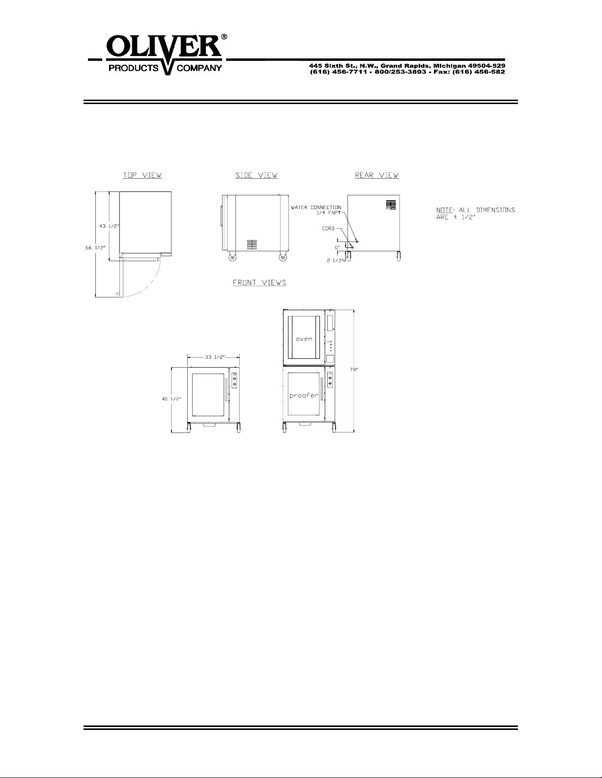
Space Requirements:
Figure 1.0
single: 43 1/2” Deep x 33 1/2” Wide x 40-1/2” high. (with casters)
stacked oven and proofer with casters: 78”
Clearance:
Left side = 2”.
Right side = 2” with casters.
Back side = 4” to allow for water connection.
Net Weight: Approximately 300 pounds.
Shipping Weight: Approximately 395 pounds.
0695S20003 2-2
695 PROOFER
OLIVERPRODUCTS.COM
INSTALLATION / SETUP
Inspection
Before accepting delivery inspect the carton and machine for damage. Note any damage
found on the shipping documents. Remember shipping damage is not
warranty, and is the responsibility of the carrier. Also report the damage to the dealer
from which the proofer was purchased for further direction and assistant in filing a claim
with the carrier.
Location Selection
Select a location where the proofer will be used. The proofer must be set on a flat level
surface. It should have a grounded power supply of the same rating as shown on the
nameplate located on the rear of the proofer and this power supply must be capable of
carrying the load that the proofer will put on it (See “Electrical Connection” page 3-2). The
proofer must also be placed near a water supply. (See “Water Connection” below).
Proofers with casters should be placed so that they have a minimum of two inches on
each side and a minimum of four inches in the rear of the proofer to provide for proper
water, and electrical connections.
Proofer Setup
Proofers may stand alone or be stacked with a Oliver oven ( oven must be on top of
proofer ). For associated mounting heights for the above options see figure 3.0 on page
2-2.
covered by your
CAUTION
USE CARE WHENEVER MOVING OVENS MOUNTED ON PROOFERS AS THEY ARE
TOP HEAVY AND PRESENT A TIPPING HAZARD.
A stacked oven should be setup as shown on page 2-2 being sure that the alignment pins
on the top of the lower proofer are securely positioned into the holes in the base of the
upper oven.
0695S20004 3-1
695 PROOFER
OLIVERPRODUCTS.COM
Electrical Connection
WARNING
THE PROOFER MUST BE CONNECTED TO A PROPERLY GROUNDED ELECTRICAL
SOURCE OF THE SAME RATING AS THE MACHINE. FAILURE COULD RESULT IN
AN ELECTRICAL SHOCK WHICH MAY CAUSE INJURY OR DEATH.
WARNING
ALL WIRING AND ELECTRICAL REPAIRS SHOULD BE DONE BY A QUALIFIED
ELECTRICIAN. FAILURE TO DO SO MAY CAUSE SERIOUS INJURY OR DEATH.
CAUTION
A SPECIAL HEAVY DUTY ELECTRICAL SERVICE MUST BE PROVIDED FOR SAFE
OPERATION OF THE PROOFER.
The following service requirements are recommended, dependent on the voltage of the
unit you have purchased. Your proofer’s requirements can be found on the nameplate
attached to its rear surface.
For voltages other than those shown below please contact the factory.
1 phase, 60 hz, 115VAC, 14.5 Amps.
( 20 amp Dedicated Circuit
The proofer is shipped from the factory with a power cord. Leave at least two feet of slack
so that access can be gained to the proofers right side. This makes sliding the proofer out
for service more convenient. Whatever method is used the proofer should be wired in a
manner which would conform to the U.S. “National Electric Code”.
)
0695S20004 3-2
695 PROOFER
OLIVERPRODUCTS.COM
Water Connection
All water connections must comply with the basic plumbing code of the Building Officials
and Code Service Sanitation Manual of the Food and Drug Administration (FDA)
CAUTION
WATER PRESSURES GREATER THEN RECOMMENDED CAN CAUSE EXCESS
WATER TO ENTER THE PROOFER CAUSING WATER TO LEAK AT THE DOOR AND
ALSO CAUSE THE HUMIDITY TO DROP SEVERELY AFFECTING THE PROOF. USE
A PRESSURE REGULATOR TO REGULATE THE PRESSURE.
The proofer must be connected to a water supply to enable the proofer to produce
humidity for baking. As shipped from the factory the proofer will have a water connection
point at the back of the proofer, (See figure 3.0 page 2-2). This connection has an internal
1/4” NPT thread. Water pressure should be a maximum of 60 to 70 PSI and the water
must clean. Use a pressure regulator and a water strainer/filter to meet these guidelines.
Before making the water connection flush all lines and install the regulator and filter.
Remember solenoid failure and related problems caused by dirt may not be covered by
your warranty.
NOTE
HARD WATER LEAVES MINERAL DEPOSITS ON GLASS AND OTHER SURFACES
WHICH DETRACT FROM PROOFERS APPEARANCE.
Test Cycle
After completing the Set Up, Electrical and Water connections, you may wish to run the
proofer through a test cycle to verify that everything is ready. Use the following sequence
to run the proofer through a test cycle.
• Turn the power switch on – internal fan should run.
• Set temperature control to highest setting – proofer should begin to heat. (allow
• Set temperature control to off, humidity control to highest setting – water tray
Revised 8-12-03
several minutes).
should begin to fill and shut-off when proper level has been reached. water should
also begin to heat. (allow several minutes).
0695S20004 3-3
695 PROOFER
OLIVERPRODUCTS.COM
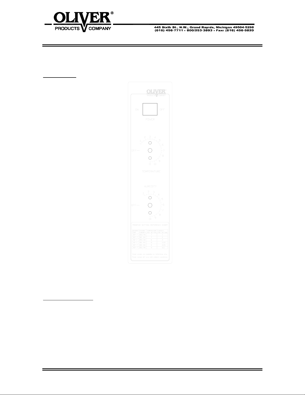
Control Panel
OPERATING INSTRUCTIONS – MANUAL CONTROLS
Figure 2.0
Beginning Operation
First turn the proofer on using the power switch.
Set desired temperature and humidity using the chart (figure 3.0, page 4-2) as a guide.
Allow several minutes for the proofer to reach desired settings.
Place pans in proofer, check frequently until proper proof has been achieved.
0695S20005 4-1
695 PROOFER
OLIVERPRODUCTS.COM
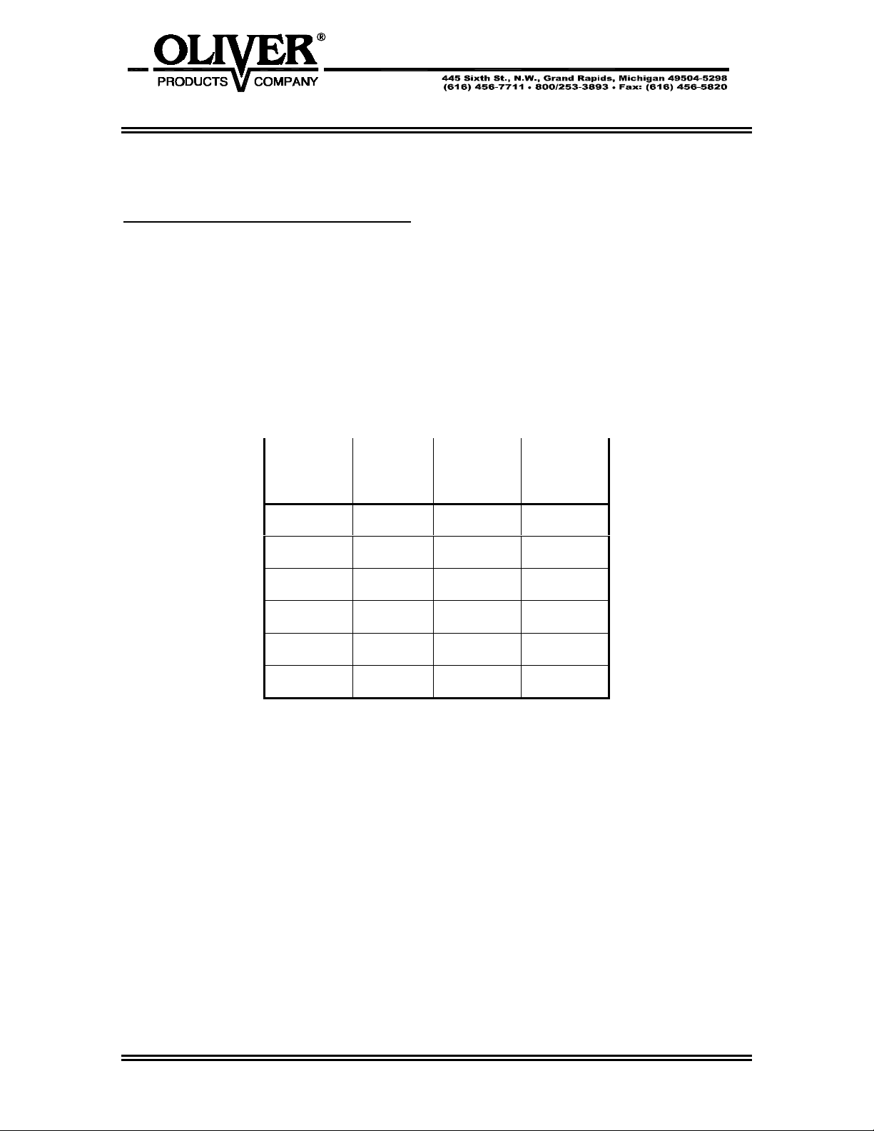
Temperature – Humidity Reference Chart
Figure 3.0
Proofer Setting Reference Chart
Desired Desired Temp. Humidity
Temp. Humidity Dial Setting Dial Setting
85º F 85% RH 7 1
85º F 90% RH 7 2
90º F 85% RH 8 2
90º F 90% RH 8 2.25
95º F 90% RH 9 2.25
95º F 95% RH 9 2.5
These values are supplied as reference only.
These values will vary with ambient conditions.
0695S20005 4-2
695 PROOFER
OLIVERPRODUCTS.COM
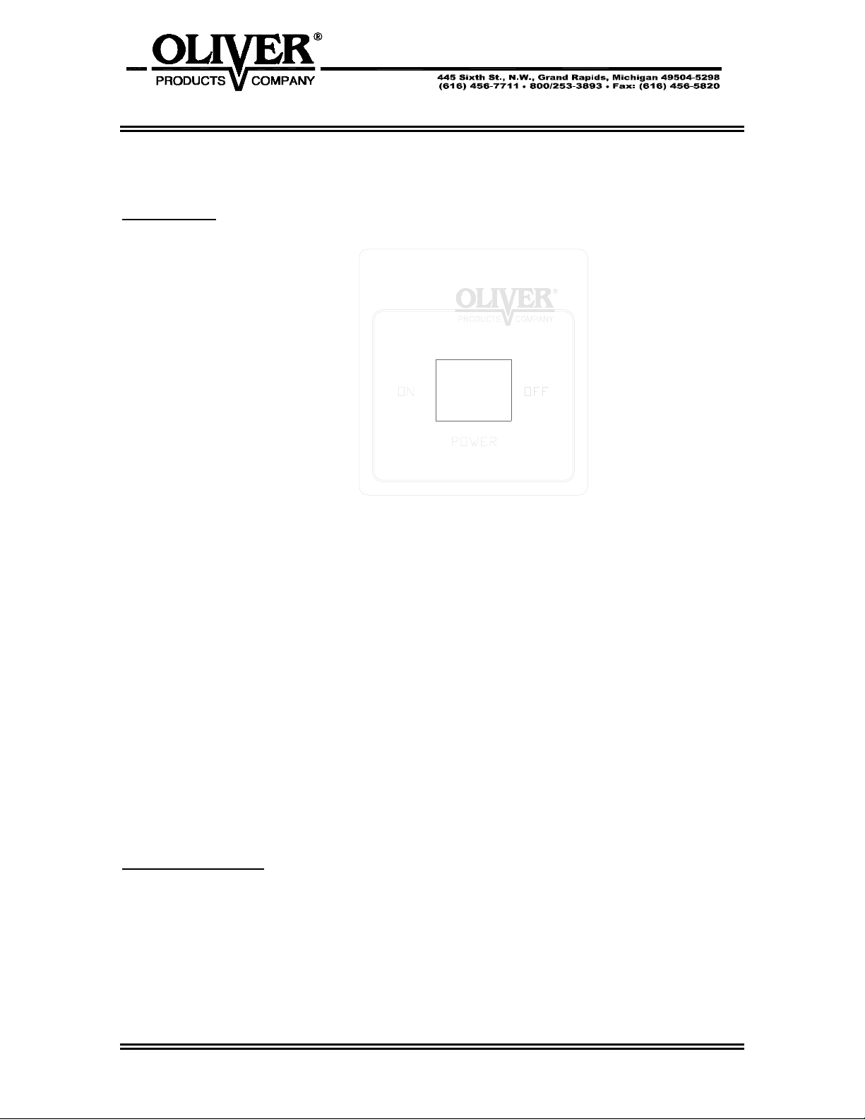
Control Panel
OPERATING INSTRUCTIONS – DIGITAL CONTROLS
Figure 4.0
Beginning Operation
First turn the Proofer on using the power switch.
Proofer will start preheating to last set temperature and humidity. (PrEH will be displayed
until unit has reached temperature and RH settings then REAdy will be displayed –
Proofing can now be started).
(continued)
0695S20005 4-3

695 PROOFER
OLIVERPRODUCTS.COM
Beginning Operation
(continued)
Indicator LED’s show when heat and / or steam are on.
Up and Down Keys
The Up and Down keys are used to adjust settings (either Time, Temperature, or RH).
Settings (as opposed to actual readings) are recognized on the display by 2 things:
the left most triangle is lit (i.e.
means that 80º C is the set point, and not the
actual temperature); the Up/Down keys LED’s are also lit, meaning that they are usable to
modify the displayed data.
To modify a setting, first press the required button for 2 seconds (Temperature or RH) and
then use the Up or Down keys to modify it. To modify proofing Time, simply press Up or
Down key directly when countdown time is displayed (while Proofing) or if Standby or Auto
states are active.
After changing settings, there are up to 3 ways to accept the new values:
• Re-press the Temperature or RH key (if changing one of those settings)
• Press the Start key “I”
• Wait for 5 seconds
In any case, if a proofing cycle was already active when the setting was changed, it will
simply continue with the new values. If the changed setting was Time, the new time is
used (i.e. the Proofing cycle is restarted using the new Time).
When accepting a change, the Up/Down LED’s shut off (as well as the Temperature or
RH LED’s and the settings triangle), and the display reverts to the previous state display
(Proofing if Start was pressed).
Temp Key
A normal press of this key forces the display to show the current Temperature reading.
If the Temp key is held for 2 seconds, the display will show the current Temperature
setting. Temp key, as well as Up and Down LED’s are also lit, indicating that Temp setting
can be changed if needed.
In either case, the display reverts back to its previous mode after 5 seconds of no activity.
(continued)
0695S20005 4-4

695 PROOFER
OLIVERPRODUCTS.COM
Beginning Operation
(continued)
RH Key
A normal press of this key forces the display to show the current RH reading.
If the RH key is held for 2 seconds, the display will show the current RH setting. RH key,
as well as Up and Down LED’s are also lit, indicating that RH setting can be changed if
needed.
In either case, the display reverts back to its previous mode after 5 seconds of no activity.
Start and Stop keys
These keys control the various states of the unit. Pressing Start “I” normally starts a
Proofing cycle with the currently memorized settings (Time, Temperature, and RH).
Pressing the Stop key “O” cancels the current Proofing cycle if one is active. The unit
returns to Off/Standby mode.
Time
Timer information is the default view in most states. The unit displays the time left if
Proofing, or the current set time if in Off/Standby state.
Time is displayed in the standard HH:MM format. During the Proofing cycle, the time is
also displayed as HH:MM; however, in the last 10 minutes of a Proofing cycle, MM:SS are
displayed. Maximum time programmable is 11 hours and 59 minutes.
If time is set to 0:00, then it is assumed the user does not wish to use the timing functions,
and the display will default to displaying current temperature when proofing. Standby in
this case shows the current temperature too. Start button is not lit in this case either.
All other functions work normally.
0695S20005 4-5
695 PROOFER
OLIVERPRODUCTS.COM
TROUBLESHOOTING
WARNING
TROUBLE SHOOTING OF ELECTRICAL EQUIPMENT SHOULD BE PERFORMED BY
QUALIFIED PERSONNEL ONLY. ELECTRICAL POTENTIAL IS GREAT ENOUGH TO
CAUSE INJURY OR DEATH.
WARNING
NEVER ATTEMPT TO SERVICE THIS PROOFER UNTIL IT HAS BEEN
DISCONNECTED FROM THE POWER SUPPLY. ALL ELECTRICAL WORK MUST BE
DONE BY A QUALIFIED ELECTRICIAN.
CAUTION
BEFORE WORKING ON A PROOFER WHICH HAS BEEN RECENTLY USED
ALLOW SUFFICIENT TIME FOR IT TO COOL TO PREVENT BURNS.
No Power.
• The machine is not plugged in.
• There is no power available at the outlet/disconnect
No Heat or Proofer Heats Slowly.
Allow several minutes for proofer to achieve desired setting. A cooled empty proofer can
be heated from room temperature to 90 °F in five to ten minutes. If the proofer is not
meeting this specification, check the following.
• Power switch is in off position.
• Temperature setting too low.
• Check fan in air duct for proper operation.
• Check the thermostat (upper manual control) or controller (digital proofer) for proper
function.
• Check to see if the heating element in air duct is functioning.
(continued)
Revised 8-14-03
0695S20006 5-1

695 PROOFER
OLIVERPRODUCTS.COM
No Humidity or Proofer Reaches Humidity Slowly.
• Power switch is in off position.
• Humidity setting too low.
• Check fan in air duct for proper operation.
• Check thermostat (lower manual control) or controller (digital proofer) for proper
operation.
• Check to see if the heating element under water tray is functioning.
No Water
• Power switch is in off position.
• Humidity setting too low – only fills when humidity is needed.
• The water line to the proofer may not have been turned on or someone has turned it
off.
• Your water line filter may be plugged or need servicing.
• The water solenoid valve may be dirty and stuck shut.
• The water solenoid valve may have failed.
• Check float switch for proper operation.
Water Is Leaking From the Door
It is normal for some condensation to drip from the door during operation, however, if
excessive amounts of water are leaking from door you should check the following.
• Check float switch for proper operation.
• The water solenoid valve may be dirty and stuck open.
The Proofer is Proofing Unevenly
• Check fan in air duct for proper operation
Revised 8-14-03
0695S20006 5-2

695 PROOFER
OLIVERPRODUCTS.COM
MAINTENANCE
WARNING
NEVER ATTEMPT TO CLEAN OR SERVICE THIS PROOFER UNTIL IT HAS BEEN
DISCONNECTED FROM THE POWER SUPPLY AND IS COOL TO THE TOUCH.
NOTE
REMEMBER A CLEAN PROOFER WILL LAST LONGER AND WORK BETTER.
Cleaning
The outside of the proofer should be cleaned daily by wiping it with a clean damp cloth or
by using any suitable stainless steel cleaner. A solution made up of a mild detergent with
water will normally be sufficient for routine cleaning of the interior of the proofer. When
finished dry the surfaces with a clean cloth.
The polycarbonate door should be cleaned daily using normal glass cleaners.
To simplify major cleanings the shelf racks may be removed by first removing the eight
thumb srews which hold the racks in place.
The proofer door also may be lifted off for easier access during cleaning.
Clean the water tray frequently to insure efficiency and to eliminate any bacterial growth.
The heating elements themselves normally do not require cleaning.
Lubrication
Occasionally put a few drops of oil on the pivot points of the door. No other items requires
lubrication.
CAUTION
NEVER LUBRICATE THE MOTORS
Revised 8-12-03
0695S20007 6-1

695 PROOFER
OLIVERPRODUCTS.COM
Electrical Component Replacement
WARNING
NEVER ATTEMPT TO SERVICE THIS PROOFER UNTIL IT HAS BEEN
DISCONNECTED FROM THE POWER SUPPLY. ALL ELECTRICAL WORK MUST BE
DONE BY A QUALIFIED ELECTRICIAN.
• Remove the front side panel which is located on the control side.
• After identifying the component which needs to be replaced remove its wires after
marking them for ease of replacement.
• Remove the component.
• Re-install the component by reversing the removal procedures.
0695S20007 6-2

695 PROOFER
OLIVERPRODUCTS.COM
RECOMMENDED SPARE PARTS
PART NUMBER
PART DESCRIPTION NO. REQ’D
5757-3307 Switch – Rocker 1
0695-0019 Switch – Float 1
5730-2656 Heater – Tubular air 1
5730-2657 Heater – Tubular water 1
5148-6770 Valve - Solenoid 1
0695-0025 Motor - Fan 1
6310-5027 Fan-Axial 3000 RPM (Cooling Fan) 1
5148-5784 Valve – Needle 1
Specific to Manual Proofer
5759-2000 Thermostat – Bulb and Cap (40-105 deg.) 1
5759-2001 Thermostat – Bulb and Cap (85-230 deg.) 1
5759-2050 Knob – Instrument 2
5749-8024 Relay-Power SPDT, 360w 2
Specific to Digital Proofer
5712-4025 Overlay – Proofer Control 1
5749-8027 Relay – DPST 20A 120V Coil 2
5749-8024 Relay-Power SPDT, 360w 1
For Service Parts Call Oliver Products @ 800-253-3893
Revised 4-5-04
0695S20008 7-1

695 PROOFER
OLIVERPRODUCTS.COM
ELECTRICAL PANEL – MANU AL CONT ROLS
Revised 8-14-03
0695S20009 8-1

695 PROOFER
OLIVERPRODUCTS.COM
ELECTRICAL PANEL PARTS LIST – MANUAL CONTROLS
ITEM NO PART DESCRIPTION PART NUMBER
208 SEE WATER SYSTEM LIST (PG. 11-2)
253 SEE WATER SYSTEM LIST (PG. 11-2)
601 HEATER-TUBULAR AIR 5730-2656
603 MOTOR-FAN 0695-0025
606* FAN-2 1/8 DIA. ALUM 5114-0010
607* FAN-5.3 DIA ALUM 5114-0020
608 RELAY-POWER SPDT 5749-8024
609 THERMOSTAT-BULB AND CAP 5759-2000
610 KNOB-INSTRUMENT 5759-2050
612 THERMOSTAT-BULB AND CAP 5759-2001
613 SWITCH-ROCKER DPST 5757-3307
614* CORD-POWER 0695-0026
615* BUSHING-STRNRLF .27-.464 GRIP 5765-1082
617 BLOCK-TERM DBL RW 8 CIRC 5770-7451
618 STRIP-MRKR DBL RW 8 CIRC 5770-7328
619* JUMPER-TERMINAL BLOCK 5770-7461
645 FAN-AXIAL 3000 RPM 6310-5027
646* CORD-FAN POWER 0695-0044
647* BRACKET-FAN MOUNTING 0695-0043
654* PLUG – 20A / 125V 5765-2023
* ITEMS NOT SHOWN IN ILLUSTRATION.
FOR SERVICE PARTS CALL OLIVER PRODUCTS @ 800-253-3893
Revised 8-14-03
0695S20009 8-2

695 PROOFER
OLIVERPRODUCTS.COM
ELECTRICAL PANEL – DIGITAL CONTROLS
Revised 4-5-04
0695S20009 8-3

695 PROOFER
OLIVERPRODUCTS.COM
ELECTRICAL PANEL PARTS LIST – DIGITAL CONTROLS
ITEM NO PART DESCRIPTION PART NUMBER
208 SEE WATER SYSTEM LIST (PG. 11-2)
253 SEE WATER SYSTEM LIST (PG. 11-2)
601 HEATER-TUBULAR AIR 5730-2656
603 MOTOR-FAN 0695-0025
606* FAN-2 1/8 DIA. ALUM 5114-0010
607* FAN-5.3 DIA ALUM 5114-0020
608 RELAY-POWER SPDT 5749-8024
613 SWITCH-ROCKER DPST 5757-3307
614* CORD-POWER 0695-0026
615* BUSHING-STRNRLF .27-.464 GRIP 5765-1082
617 BLOCK-TERM DBL RW 8 CIRC 5770-7451
618 STRIP-MRKR DBL RW 8 CIRC 5770-7328
619* JUMPER-TERMINAL BLOCK 5770-7461
645 FAN-AXIAL 3000 RPM 6310-5027
646* CORD-FAN POWER (DIGITAL) 0695-0044-001
654* PLUG – 20A / 125V 5765-2023
657 RELAY-DPST 20A 120V COIL 5749-8027
658 COMPUTER-PROOFER ECM-2 0695-0065
659 OVERLAY-PROOFER CONTROL 5712-4025
660 SENSOR-PROBE TEMP/HUMIDITY 5712-0670
* ITEMS NOT SHOWN IN ILLUSTRATION.
FOR SERVICE PARTS CALL OLIVER PRODUCTS @ 800-253-3893
Revised 4-5-04
0695S20009 8-4

695 PROOFER
OLIVERPRODUCTS.COM
DOOR ASSEMBLY
0695S20010 9-1

695 PROOFER
OLIVERPRODUCTS.COM
DOOR ASSEMBLY PARTS LIST
ITEM NO PART DESCRIPTION PART NUMBER
501 FRAME-REAR DOOR 0695-0011
502 GASKET-OVEN DOOR 6904-6062
503 PLATE-MAGNET 0695-0023
506 PANEL-LEXAN 0695-0013
507 FRAME-FRONT DOOR 0695-0012-001
509 HANDLE-STST TUBULAR 5908-5116
511 HINGE-STST SLIP 0695-0024
FOR SERVICE PARTS CALL OLIVER PRODUCTS @ 800-253-3893
0695S20010 9-2

695 PROOFER
OLIVERPRODUCTS.COM
HOUSING/CHAMBER ASSEMBLY
Revised 4-5-04
0695S20011 10-1

695 PROOFER
OLIVERPRODUCTS.COM
HOUSING/CHAMBER PARTS LIST
ITEM NO PART DESCRIPTION PART NUMBER
001 PANEL-BOTTOM 0695-0001-1
002 CHAMBER-INNER 0695-0002
005 PAN-20-3/4 X 6-3/8 5915-3003
006 MAGNET-PLUG 5827-3000
007 CLAMP-MAGNET 0695-0017
010 DUCT-AIR BAY MOTOR 0695-0003
(MANUAL CONTROLS)
010 DUCT-AIR BAY MOTOR 0695-0003-001
(DIGITAL CONTROL)
011 DEFLECTOR-HEAT 0695-0004
012 SPACER 0695-0018
014 CLIP-ADJUSTABLE 5902-9008
018 DEFLECTOR-DRIP 0695-0046
020 PLATE-FAN MOUNTING 0695-0066
(MANUAL CONTROLS)
020 PLATE-FAN MOUNTING 0695-0067
(DIGITAL CONTROL)
101 PLATE-CASTER 0690-0076
102 CASTER-RIGID PLATE 5902-2440
103 CASTER-SWIVEL PLATE 5902-2441
209 SEE WATER SYSTEM LIST (PG. 11-2)
409 SEE COVERS/RACKS LIST (PG. 12-2)
601 SEE ELECTRICAL PANEL LIST (PG. 8-2)
607 SEE ELECTRICAL PANEL LIST (PG. 8-2)
647 SEE ELECTRICAL PANEL LIST (PG. 8-2)
FOR SERVICE PARTS CALL OLIVER PRODUCTS @ 800-253-3893
Revised 4-5-04
0695S20011 10-2

695 PROOFER
OLIVER PROD UCTS .COM
WATER SYSTEM ASSEMBLY
0695S20012 11-1

695 PROOFER
OLIVER PROD UCTS .COM
WATER SYSTEM ASSEMBLY PARTS LIST
ITEM NO PART DESCRIPTION PART NUMBER
201 SWITCH-FLOAT 0695-0019
203 TUBE-FILL 0695-0045
204* CONNECTOR-MALE 5115-2744
205* ANCHOR-COUPLING 5115-1582
206* MALE CONNECTOR 5115-6261
207* TUBING-POLYETHYLENE 6528-6620
208 VALVE-WATER SOLENOID 5148-6770
209 BRACKET-WATER VALVE 0695-0020
210* FITTING-FEMALE CONNECTOR 5115-6231
218* VALVE-NEEDLE 5148-5784
251 TRAY-WATER 0695-0014
252 COVER-HEATER 0695-0015
253 HEATER-TUBULAR WATER 5730-2657
256 CLAMP 0695-0016
257 PLATE-HEATER INTERFACE 0695-0068
* ITEMS NOT SHOWN IN ILLUSTRATION.
FOR SERVICE PARTS CALL OLIVER PRODUCTS @ 800-253-3893
0695S20012 11-2

695 PROOFER
OLIVERPRODUCTS.COM
COVERS / RACKS ASSEMBLY
0695S20013 12-1

695 PROOFER
OLIVERPRODUCTS.COM
COVERS / RACKS ASSEMBLY PARTS LIST
ITEM NO PART DESCRIPTION PART NUMBER
301 RACK-8 SHELF 0695-0021
302 SCREW-THUMB 5843-0536
401 COVER-LH SIDE 0695-0005
404 COVER-TOP 0695-0006-1
405 CHANNEL-NUT 0695-0022
409 COVER-FRONT (MANUAL CONTROLS) 0695-0007-1
409 COVER-FRONT (DIGITAL CONTROLS) 0695-0007-001
410 COVER-RH SIDE REAR 0695-0008
411 PANEL-ACCESS (MANUAL CONTROLS) 0695-0009
411 PANEL-ACCESS (DIGITAL CONTROL) 0695-0009-001
412 PANEL-REAR 0695-0010
FOR SERVICE PARTS CALL OLIVER PRODUCTS @ 800-253-3893
Revised 4-5-04
0695S20013 12-2

695 PROOFER
OLIVERPRODUCTS.COM
115V WIRING DIAGRAM – MANUAL CONTROLS #0695C12000
Revised 8-14-03
0695S20014 13-1

695 PROOFER
OLIVERPRODUCTS.COM
115V WIRING DIAGRAM – DIGITAL CONTROLS #0695C12001
Revised 4-5-04
0695S20014 13-2

WARRANTY
PARTS
Oliver Products Company (Oliver) warrants that if any part of the equipment (other than a part not
manufactured by Oliver) proves to be defective (as defined below) within one year after shipment,
and if Buyer returns the defective part to Oliver within one year, Freight Prepaid to Oliver’s plant in
Grand Rapids, MI, then Oliver, shall, at Oliver’s option, either repair or replace the defective part, at
Oliver’s expense.
LABOR
Oliver further warrants that equipment properly installed in accordance with our special instructions,
which proves to be defective in material or workmanship under normal use within one (1) year from
installation or one (1) year and three (3) months from actual shipment date, whichever date comes
first, will be repaired by Oliver or an Oliver Authorized Service Dealer, in accordance with Oliver’s
published Service Schedule.
For purposes of this warranty, a defective part or defective equipment is a part or equipment which is
found by Oliver to have been defective in materials workmanship, if the defect materially impairs the
value of the equipment to Buyer. Oliver has no obligation as to parts or components not
manufactured by Oliver, but Oliver assigns to Buyer any warranties made to Oliver by the
manufacturer thereof.
This warranty does not apply to:
1. Damage caused by shipping or accident.
2. Damage resulting from improper installation or alteration.
3. Equipment misused, abused, altered, not maintained on a regular basis, operated carelessly, or
used in abnormal conditions.
4. Equipment used in conjunction with products of other manufacturers unless such use is approved
by Oliver Products in writing.
5. Periodic maintenance of equipment, including but not limited to lubrication, replacement of wear
items, and other adjustments required due to installation, set up, or normal wear.
6. Losses or damage resulting from malfunction.
The foregoing warranty is in lieu of all other warranties expressed or implied AND OLIVER MAKES
NO WARRANTY OF MERCHANTABILITY OR FITNESS FOR PURPOSE REGARDING THE
EQUIPMENT COVERED BY THIS WARRANTY. Oliver neither assumes nor authorizes any person
to assume for it any other obligations or liability in connection with said equipment. OLIVER SHALL
NOT BE LIABLE FOR LOSS OF TIME, INCONVENIENCE, COMMERCIAL LOSS, INCIDENTAL OR
CONSEQUENTIAL DAMAGES.
GEN 040225

THIS PAGE WAS INTENTIONALLY
LEFT BLANK.
GEN020319

WARRANTY PROCEDURE
1. If a problem should occur, either the dealer or the end user must contact the Customer
Service Department and explain the problem.
2. The Customer Service Manager will determine if the warranty will apply to this particular
problem.
3. If the Customer Service Manager approves, a Work Authorization Number will be
generated, and the appropriate service agency will perform the service.
4. The service dealer will then complete an invoice and send it to the Customer Service
Department at Oliver Products Company.
5. The Customer Service Manager of Oliver Products Company will review the invoice and
returned parts, if applicable, and approve for payment.
GEN 040226

THIS PAGE WAS INTENTIONALLY
LEFT BLANK.
GEN020319

RETURNED PARTS POLICY
This policy applies to all parts returned to the factory whether for warranted credit,
replacement, repair or re-stocking.
Oliver Products Company requires that the customer obtain a Return Material Authorization
(RMA) number before returning any part. This number should appear on the shipping label
and inside the shipping carton as well. All parts are to be returned prepaid. Following this
procedure will insure prompt handling of all returned parts.
To obtain an RMA number contact the Repair Parts Deptartment toll free at (800) 253-3893.
Parts returned for re-stocking are subject to a RE-STOCKING CHARGE.
Thank you for your cooperation,
Repair Parts Manager
Oliver Products Company
GEN 040227
 Loading...