

Oliver 691 Parts List

Grand Rapids, Michigan, U.S.A. 49504-5298
USER’S OPERATING AND INSTRUCTION MANUAL
MODEL 691 & 691-S
CONVECTION & CONVECTION WITH STEAM OVENS
691S20000-CV

691 & 691-S Electric Convection Ovens
OLIVERPRODUCTS.COM
INDEX
Section Description Document No. Page No.
SAFETY INSTRUCTIONS ------------------------------- 0691S20002 --------------------- 1-1
DESCRIPTION/SPECIFICATIONS ------------------- - 0691S20003------------- --------- 2-1
Description -------------------------------------------------------------------------------------- 2-1
Physical Specifications----------------------------------------------------------------------- 2-1
INSTALLATION / SETUP -------------------------------- 0691S20004 --------------------- 3-1
Inspection --------------------------------------------------------------------------------------- 3-1
Location Selection ---------------------------------------------------------------------------- 3-1
Sealing Oven to Mounting Surface ------------------------------------------------------- 3-1
Oven Setup ------------------------------------------------------------------------------------- 3-2
Electrical Connection ------------------------------------------------------------------------- 3-2
Water Connection ----------------------------------------------------------------------------- 3-4
Venting ------------------------------------------------------------------------------------------- 3-5
Test Cycle --------------------------------------------------------------------------------------- 3-5
OPERATING INSTRUCTIONS ------------------------- 0691S20005 --------------------- 4-1
Beginning Operation ------------------------------------------------------------------------- 4-1
The Keyboard and Displays --------------------------------------------------------------- 4-1
Idle Mode --------------------------------------------------------------------------------------- 4-2
Running an Automatic Program ---------------------------------------------------------- 4-2
Running Two Automatic Programs at the Same Time ------------------------------ 4-3
Pre-Alarm -------------------------------------------------------------------------------------- 4-3
Running a Manual Program --------------------------------------------------------------- 4-3
Adjusting the Temperature ----------------------------------------------------------------- 4-4
Adding Steam --------------------------------------------------------------------------------- 4-5
Opening and Closing the Vent ------------------------------------------------------------ 4-5
Changing the Fan Setting ------------------------------------------------------------------ 4-5
PROGRAMMING ------------------------------------------- 0691S20006 --------------------- 5-1
TROUBLESHOOTING ------------------------------------ 0691S20007 --------------------- 6-1
Error Code Display --------------------------------------------------------------------------- 6-1
Solving Other Problems --------------------------------------------------------------------- 6-2
Advanced Functions ------------------------------------------------------------------------- 6-5
Advanced Setup Mode (Re-calibration) ------------------------------------------------- 6-6
MAINTENANCE -------------------------------------------- 0691S20008 --------------------- 7-1
Cleaning ----------------------------------------------------------------------------------------- 7-1
Lubrication -------------------------------------------------------------------------------------- 7-1
Removal and Replacement Guide ------------------------------------------------------- 7-2
RECOMMENDED SPARE PARTS -------------------- 0691S20009 --------------------- 8-1
Continued
0691S20001 0-1
691 & 691-S Electric Convection Ovens
OLIVERPRODUCTS.COM
INDEX (Continued)
Section Description
Document No. Page No.
REPLACEMENT PARTS SECTION
HOUSING / CHAMBER ASSEMBLY ----------------- 0691S20010 -------------------- 9-1
Drawing ---------------------------------------------------------------------------------------- 9-1
Parts List --------------------------------------------------------------------------------------- 9-2
DAMPER ASSEMBLY ------------------------------------ 0691S20011 ------------------- 10-1
Drawing ---------------------------------------------------------------------------------------- 10-1
Parts List -------------------------------------------------------------------------------------- 10-2
WATER SYSTEM ----------------------------------------- 0691S20012 -------------------- 11-1
Drawing ---------------------------------------------------------------------------------------- 11-1
Parts List -------------------------------------------------------------------------------------- 11-2
DOOR ASSEMBLY ---------------------------------------- 0691S20013 -------------------- 12-1
Drawing ---------------------------------------------------------------------------------------- 12-1
Parts List -------------------------------------------------------------------------------------- 12-2
FRONT CONTROL PANEL ASSEMBLY------------- 0691S20014 -------------------- 13-1
Drawing ---------------------------------------------------------------------------------------- 13-1
Parts List -------------------------------------------------------------------------------------- 13-2
ELECTRICAL SUB PANEL ------------------------------ 0691S20015 --------------------- 14-1
Drawing ----------------------------------------------------------------------------------------- 14-1
Parts List --------------------------------------------------------------------------------------- 14-2
REAR COVER ASSEMBLY ----------------------------- 0691S20016 -------------------- 15-1
Drawing ---------------------------------------------------------------------------------------- 15-1
Parts List -------------------------------------------------------------------------------------- 15-2
COVER ASSEMBLY -------------------------------------- 0691S20017 ------------------- 16-1
Drawing ---------------------------------------------------------------------------------------- 16-1
Parts List -------------------------------------------------------------------------------------- 16-2
ELECTRICAL DIAGRAM -------------------------------- 069S20018 -------------------- 15-1
Wiring Diagram 208 / 240 375 / 480 V -------------------------------------------------- 15-1
WARRANTY ------------------------------------------------- GEN 040225
WARRANTY PROCEDURE ----------------------------- GEN 040226
RETURNED PARTS POLICY---------------------------- GEN 040227
REV. 2/26/04
0691S20001 0-2
691 & 691-S Electric Convection Ovens
OLIVERPRODUCTS.COM
SAFETY INSTRUCTIONS
WARNING
VARIOUS SAFETY DEVICES AND METHODS OF GUARDING HAVE BEEN
PROVIDED ON THIS OVEN. IT IS ESSENTIAL HOWEVER THAT THE OVEN
OPERATORS AND MAINTENANCE PERSONNEL OBSERVE THE FOLLOWING
SAFETY PRECAUTIONS. IMPROPER INSTALLATION, MAINTENANCE, OR
OPERATION COULD CAUSE SERIOUS INJURY OR DEATH.
1. Read this manual before attempting to operate your oven. Never allow an untrained
person to operate or service this machine.
2. This oven must only be installed by qualified personnel. It also must be installed to
the specifications of local plumbing and electrical codes. See the installation section
of this manual for additional requirements.
3. Connect the oven to a properly grounded electrical supply that matches the
requirements shown on the electrical specification plate and follow specifications of
local electrical codes.
4. Disconnect and lock-out the oven from the power supply before cleaning or servicing.
5. Check and secure all guards before starting the oven.
6. Observe all caution and warning labels affixed to the oven.
7. Use only proper replacement parts.
8. Wear proper personal protective safety equipment.
9. Keep Hands away form the moving parts of this oven while it is in operation.
10. In addition to these general safety instructions, also follow the more specific safety
instructions given for the different areas of the oven in the operating instructions.
WARNING
DO NOT USE FOR OTHER THAN ORIGINALLY INTENDED PURPOSE.
0691S20002 1-1
691 & 691-S Electric Convection Ovens
OLIVERPRODUCTS.COM
DESCRIPTION/SPECIFICATIONS
Description
The Oven is a stainless steel, electric, forced air, (convection), oven with optional steam
injection capabilities. This oven offers consistent baking at all rack levels due to the
careful positioning of the heating and air circulation systems.
In addition to the above, this oven also offers many other features. It is well insulated with
a high quality asbestos free insulation. It is compact, attractive, quiet, and is
easily maintained. Should electrical servicing ever be required the electrical components
are readily accessible by removing the side or back panels.
The lighted, tempered glass door with its high temperature seal allows a full view of the
trays in the oven during baking.
The oven computer allows you to bake two items at once which makes the oven more
productive. It also has one of the fastest temperature recoveries on the market allowing
the oven to be turned off during non-peak hours, thus saving energy.
The oven has many protective features such as not allowing heating of the elements when
the door is open. Other features are re-settable thermal overloads on the motors, and a
high-limit thermostat.
The computer allows easy selection of baking programs. The programs combine precise
control of the pre-heat temperature, baking temperature, time, and pre-alarm functions.
Some models offer steam, and damper control. These functions offer precise baking
control by even inexperienced individuals.
Physical Specifications
Electrical Options Available:
3 phase, 60 hz, 480VAC, 14 Amps.
3 phase, 60 hz, 240VAC, 27 Amps.
3 phase, 60 hz, 208VAC, 24 Amps.
3 phase, 50 hz, 375VAC, 11 Amps
Product Capacities:
The Standard oven will hold (4) 18" X 26" pastry baking trays
these trays will be approximately 3-5/16 inches apart when in
the oven.
0691S20003 2-1
691 & 691-S Electric Convection Ovens
OLIVERPRODUCTS.COM
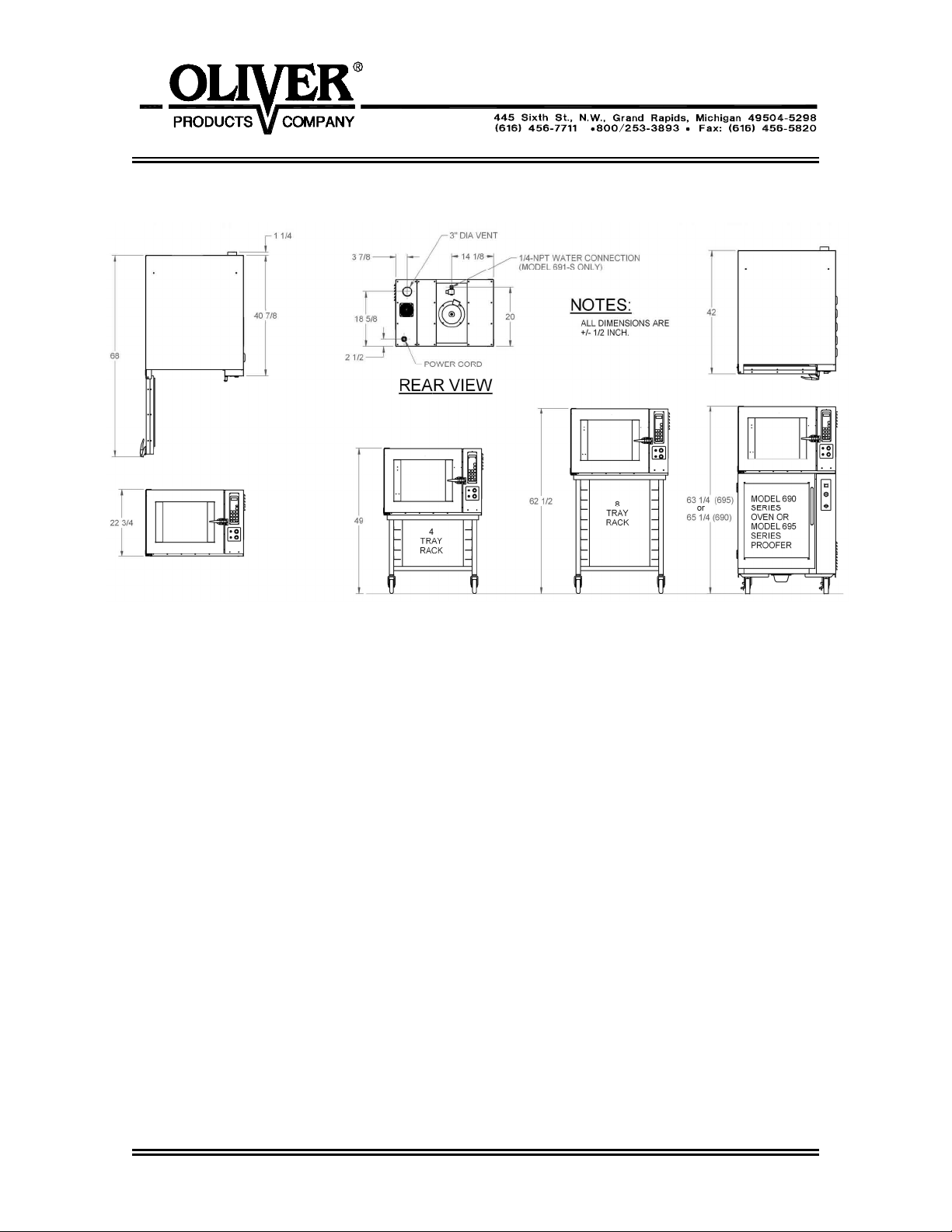
Space Requirements:
Single: 42” Deep x 33” Wide x 22-3/4” high.
Single with short stand and casters: 49” high.
Single with tall stand and casters: 62-1/2” high
Stacked 691 oven & 695 Proofer with casters: 63-1/4” high
Stacked 690 & 691 ovens with casters: 65-1/4” high
Clearance:
Left side = 2”.
Right side = 12” in a fixed location, (to have access to electrical components), or
2” when mounted on another unit which has casters.
Back side = 4” to allow for venting and optional water connections.
Net Weight: Approximately 350 pounds.
Shipping Weight: Approximately 400 pounds.
0691S20003 2-2
691 & 691-S Electric Convection Ovens
OLIVERPRODUCTS.COM
INSTALLATION / SETUP
Inspection
Before excepting delivery inspect the carton and machine for damage. Note any damage
found on the shipping documents. Remember shipping damage is not
covered by your
warranty, and is the responsibility of the carrier. Also report the damage to the dealer
from which the oven was purchased for further direction and assistant in filing a claim with
the carrier.
Location Selection
Select a location where the oven will be used. The oven must be set on a flat level
surface. It should have a grounded power supply of the same rating as shown on the
nameplate located on the rear of the oven and this power supply must be capable of
carrying the load that the oven will put on it (See “Electrical Connection” below). All ovens
must be properly vented (See “Venting” below). Model 691-S ovens must also be placed
near a water supply, (See “Water Connection” below for further information).
Ovens mounted on other units with casters should be placed so that they have a minimum
of two inches on each side and a minimum of four inches in the rear of the oven to provide
for proper venting, water, and electrical connections.
Ovens without casters should be placed so that there is a minimum of two inches on all
sides, except for the side with the electrical panel, (right side), which should have a
minimum of twelve inches. The rear of an oven without casters should be a minimum of
four inches away from adjacent surfaces to allow room for the electrical, water and venting
connections.
Sealing Oven to Mounting Surface
CAUTION
MAKE SURE THAT THE MOUNTING SURFACE IS ABLE TO SUPPORT THE WEIGHT
OF THE OVEN WHICH IS APPROXIMATELY 350 POUNDS PLUS AN ADEQUATE
SAFETY FACTOR BEFORE PLACING IT ON THE SURFACE.
The oven must be
For the purpose of sealing the unit a tube of NSF/FDA approved silicone sealant has been
provided with your unit. Apply, to the surface that the oven will rest on, a continuous bead
of sealant approximately 1/2 inch in from each of the four sides of the oven. After the
oven has been placed over this bead apply a second generous continuous bead at the
joint where the oven contacts the mounting surface thus totally sealing the bottom of the
oven to that surface.
0691S20004 3-1
sealed to the mounting surface to comply with local sanitation codes.
691 & 691-S Electric Convection Ovens
Oven Setup
Ovens may be mounted to a fixed surface, attached to an “Oliver” oven rack with casters
or stacked on either a Oliver Model 690 Oven or and Oliver Model 695 Proofer. For
associated mounting heights for the above options see page 2-2.
OLIVERPRODUCTS.COM
CAUTION
USE CARE WHENEVER MOVING OVENS MOUNTED ON RACKS AS THEY ARE TOP
HEAVY AND PRESENT A TIPPING HAZARD.
Ovens attached to “Oliver” oven racks must be
Stacked units should be setup as shown on page 2-2 being sure that the alignment pins
on the top of the lower unit are securely positioned into the holes in the base of the upper
oven.
After the Oven has been mounted to a surface, attached to a rack, or stacked, remove the
shipping bracket, which secures the door. To remove the shipping bracket, remove the
two screws from the top of the door with a screwdriver and open the door. Replace these
screws and tighten securely. To remove the shipping bracket from the front of the oven
liner, remove the two hex head screws with a wrench. The bracket and screws may be
discarded. Replace the removed hex head screws with the two screws provided in a bag
taped to the floor of the oven chamber and tighten securely.
Electrical Connection
securely fixed to the rack with bolts.
WARNING
THE OVEN MUST BE CONNECTED TO A PROPERLY GROUNDED ELECTRICAL
SOURCE OF THE SAME RATING AS THE MACHINE. FAILURE COULD RESULT IN
AN ELECTRICAL SHOCK WHICH MAY CAUSE INJURY OR DEATH.
WARNING
ALL WIRING AND ELECTRICAL REPAIRS SHOULD BE DONE BY A QUALIFIED
ELECTRICIAN. FAILURE TO DO SO MAY CAUSE SERIOUS INJURY OR DEATH.
CAUTION
SPECIAL HEAVY DUTY ELECTRICAL SERVICES AND WALL DISCONNECTS MUST
BE PROVIDED FOR SAFE OPERATION OF THE OVEN.
The following service requirements are recommended, dependent on the voltage of the
unit you have purchased. Your oven’s requirements can be found on the nameplate
attached to its rear surface.
0691S20004 3-2
691 & 691-S Electric Convection Ovens
OLIVERPRODUCTS.COM
Electrical Connection (continued)
For voltages other than those shown below please contact the factory. Check the voltage
at the disconnect before proceeding to the next step.
480 Volts = 20 Amp service
375 Volts = 20 Amp service
240 Volts = 30 Amp service
208 Volts = 30 Amp service
The oven is shipped from the factory with a power cord, which does not include a plug.
The power cord should be wired to a disconnect enclosure which is accessible from the
oven work area, leave at least two feet of slack so that access can be gained to the ovens
back and right side. A plug may be used between the disconnect enclosure and the oven
instead of hard wiring as described above. This makes sliding the oven out for service
more convenient. Whatever method is used the oven should be wired in a manner which
would conform to the U.S. “National Electric Code”.
CAUTION
FANS MUST ROTATE IN THE CLOCKWISE DIRECTION FOR PROPER AIRFLOW.
IMPROPER DIRECTION MAY CAUSE UNEVEN BAKES AND LONGER BAKING TIMES.
Check fan rotation for clockwise direction. After the oven has been “Set Up” and
connected to the electrical service do the following to check the rotation of the fans. Use
the following sequence to start the oven to check fan rotation direction:
• Turn the main power switch on, (green button). The oven should start after a
delay of 15-30 seconds. Once started the fan rotation can be checked.
• Once complete, turn the main power switch off, (red button).
If the rotation is incorrect remove and interchange any two of the three incoming power
leads (red, white and black), at the plug or disconnect enclosure and retest.
0691S20004 3-3
691 & 691-S Electric Convection Ovens
Water Connection (Model 691-S ovens only)
All water connections must comply with the basic plumbing code of the Building Officials
and Code Service Sanitation Manual of the Food and Drug Administration (FDA)
OLIVERPRODUCTS.COM
CAUTION
WATER PRESSURES GREATER THEN RECOMMENDED CAN CAUSE EXCESS
WATER TO ENTER THE OVEN CAUSING WATER TO LEAK AT THE DOOR AND
ALSO CAUSE THE TEMPERATURE TO DROP SEVERELY AFFECTING THE BAKE.
USE A PRESSURE REGULATOR TO REGULATE THE PRESSURE
The oven must be connected to a water supply to enable the oven to produce steam for
baking. As shipped from the factory the oven will have a solenoid valve at the back, upper
center of the oven, (See page 2-2). This valve has an internal 1/4” NPT thread for
connection. Water pressure should be a maximum of 60 to 70 PSI and the water must be
clean. Use a pressure regulator and a water strainer/filter to meet these guidelines
Before making the water connection flush all lines and install the regulator and filter.
Remember solenoid failure and related problems caused by dirt may not be covered by
your warranty.
.
.
NOTE
HARD WATER LEAVES MINERAL DEPOSITS ON GLASS AND OTHER SURFACES
WHICH DETRACT FROM OVEN APPEARANCE.
The solenoid valve can be checked after “Set Up” and the “Electrical and Water
Connections” has been completed. Use the following sequence to start the oven to check
solenoid operation.
• Turn the main power switch on, (green button).
• Press the steam button, (located on the computer touch panel), briefly and
release, water should spray from the spray nozzle. Adjust the spray nozzle if
required so that it sprays directly into the fan.
• Once complete, turn the main power switch off, (red button).
0691S20004 3-4
691 & 691-S Electric Convection Ovens
OLIVERPRODUCTS.COM
Venting
On the rear side of the oven near the top is a 3” diameter exhaust vent protruding
approximately 3/4” from the oven. Vent the exhaust (hot air and steam) to the outside by
connecting to this vent.
WARNING
HOT STEAM CAN CAUSE SEVERE BURNS AND DAMAGE TO THE SENSITIVE
ELECTRONICS. VENT STEAM TO OUTSIDE TO AVOID INJURIES AND DAMAGE.
Test Cycle
After completing the Set Up, Electrical, Water connections, (when required) and Venting,
you may wish to run the oven through a test cycle to verify that everything is ready. Use
the following sequence to test the oven.
• Turn the main power switch on, (green button). After a few seconds the fans
• Press the “Temp” button once this should activate the “Actual Temp Light” located
• To increase or decrease the temperature press the “Temp” button a second time.
• Set the Temperature to 350-400 degrees.
• Once the oven reaches the set temperature the heating elements should cycle on
• If you have purchased a Model 691-S oven, (with steam), you can press the steam
• Once satisfied that the oven is working properly the oven should be cooled down.
• Once complete, turn the main power switch off, (red button).
should start and “Idle” should appear in the computer display.
below the computer display. The temperature then displayed should be rising until
it achieves the “Idle” temperature of 250 degrees F.
This will activate the “Set Temp” light located below the display. By pushing either
the up or down arrow the temperature can be increased or decreased.
and off.
button, (#7 button), holding briefly, (a second or two) and then releasing. Water
should spray from the spray nozzle directly into the fan which will spread the water
onto the heating elements causing steam. Under normal conditions SOME
STEAM MAY ESCAPE THROUGH THE FRONT DOOR GASKET.
If the “Set Temp” light is not on press the “Temp” button until it is. Once this is
done press the “Fan” button, (#8), this will place the oven into cool down mode.
The door should be left open to speed this process. Once the oven has cooled
down sufficiently, proceed to the next step.
0691S20004 3-5

691 & 691-S Electric Convection Ovens
CANC
OLIVERPRODUCTS.COM
OPERATING INSTRUCTIONS
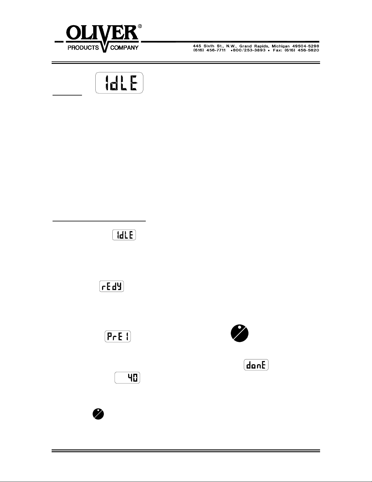
Beginning Operation
First turn the oven on by pressing the green “Start”
button below the keyboard and display. The computer
will then check the oven and itself for any faults. Then
the display will show the current mode which is idle
the preset initial temperature is 250 °F.
The Keyboard and Displays
• Press the temp. key
to toggle the display
between Time, Actual Temp., Set Temp, and Idle.
The display LED’s will light for actual and set
temperature.
• The Heat LED will light when the heating elements
are on.
• Use the up and down keys
to add
and subtract time in whole minute increments.
•
The time key is used when a bake is running.
Press this key to display the time remaining.
During 2 product baking pressing this key will
briefly display the product with the most time
remaining.
•
The temp key will change the display between
set point, set temp, and time remaining.
START
•
EL
The Start/Cancel key is pressed to start and
cancel various operations.
•
The next key is used in programming.
• Other detailed key descriptions are explained in the
next sections.
0691S20005 4-1
691 & 691-S Electric Convection Ovens
CANC
S
OLIVERPRODUCTS.COM
Idle Mode
From Idle mode you can:
• Run an automatic program.
• Run a manual program.
• Adjust the temperature.
• add steam (Model 691-S only).
• open and close the vent (Model 691-S only).
• change the fan setting.
Running an Automatic Program
1. From Idle mode
enter the program number (01 - 40) using the keypad
2. Wait 3 seconds or press the start key to begin preheat stage.
3. Wait for oven to reach set temperature. The display will show lo or hi and the menu
number. When the set point is reached the buzzer will sound and the display will
show ready
.
4. Put product into the oven.
5. Close door, bake begins.
START
6. Pre-Alarm #1 will sound if programmed, press
CANCEL
to cancel the alarm.
For more details see the Pre-Alarm section.
7. Alarm will sound when bake is finished and display will show
program number
.
. and the
Open the door to end the program, this will hold the current bake temperature, add time if
required by pressing the up button. OR
TART
EL
Press cancel
to end the bake and return the holding temperature to 250 °F.
0691S20005 4-2

691 & 691-S Electric Convection Ovens
OLIVERPRODUCTS.COM
Running two Automatic Programs at the Same Time
If two programs are compatible they may be run at the same time. They must both be
single stage menus with identical temperatures. While the program is running (Product 1
LED will be lit) enter the second program number (01-40) and hit start. Now both product
LED’s will be lit, the one with the shortest time will have a flashing LED and the time
remaining will be displayed. To briefly display the time of the other product press the Time
key
.
Pre-Alarm
The pre-alarm will go off during the bake as programmed. The alarm will sound and the
display will show
(the 1 is for product-1, product-2 pre-alarm displays )
press cancel or open the door to clear the alarm.
For advanced users: While the pre-alarm is displayed it is possible to add time to it. Do
this by pressing the up key. Press the up key once for each minute. Then wait three
seconds or press the start key. Example: by adding 2 minutes to the pre-alarm, another
pre-alarm will sound in two minutes. It is then possible to add time again and again.
If the alarm is cleared by opening the door it is still possible to add time. However if the
door is then shut and the up key isn’t pressed within three seconds, the pre-alarm will be
cleared and it will not be possible to add time.
Running a manual program
START
From idle mode
press the manual key then press start
CANCEL
.
Now enter the desired temperature by using the numeric keypad or the arrow keys to
scroll.
Press the next key
to advance. Display will show which prompts you to
enter the time.
Using the numeric keypad enter the time in minutes and seconds.
Example: Run a manual program at 350 °F for 10 minutes
Display Shows Press Button(s)...
0691S20005 4-3

691 & 691-S Electric Convection Ovens
OLIVERPRODUCTS.COM
START
CANCEL
and
START
CANCEL
Countdown begins.
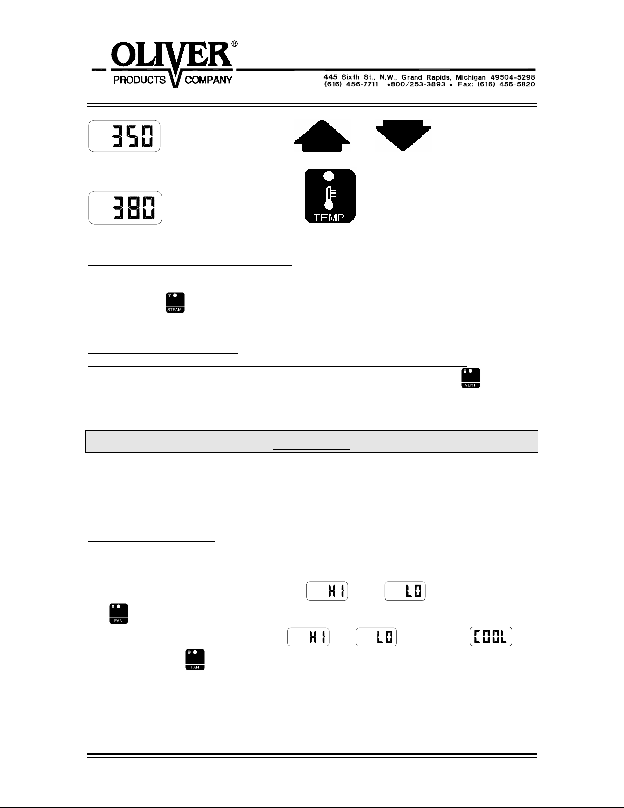
Adjusting the Temperature
The temperature can be changed while in manual or idle mode. Here is an example of
how to change the temperature from 350 to 380.
Display Shows Press Button(s)...
or
Actual temp, Press the temp key again
0691S20005 4-4
691 & 691-S Electric Convection Ovens
OLIVERPRODUCTS.COM
Set temp. Use and to scroll to 380.
Press to go back to ‘Time or Idle’.
Adding Steam (Model 691-S Ovens only)
It is possible to inject steam at any time the door is closed by pressing and holding the
7/steam button
.
Opening and Closing the Vent
(Model 691-S Ovens and Model 691 Ovens with optional powered vent only)
It is possible to toggle the vent open and closed by pressing the 8/vent key
. This will
not work when a program is running. Use this feature to vent some of the steam out of
the oven before opening the door. However, some hot steam will always remain.
CAUTION
SUPER HEATED STEAM IS INVISIBLE AND IS POSSIBLY PRESENT IN THE OVEN.
THIS STEAM MAY BURN SKIN. STAND AS FAR AS POSSIBLE AWAY FROM OVEN
WHEN OPENING THE DOOR. THEN PROCEED WITH CAUTION.
Changing the Fan Setting
The fan cannot be changed when a program is running.
In manual mode the fans can be set to high
key
.
In Idle mode the fans can be set to high
using the 9/fan key
Cool down allows the oven chamber to quickly cool down by keeping the blowers
running while the door is open.
The low fan setting is helpful for high sugar product.
or low by pressing the 9/fan
, low , or cool down
.
0691S20005 4-5
691 & 691-S Electric Convection Ovens
OLIVERPRODUCTS.COM
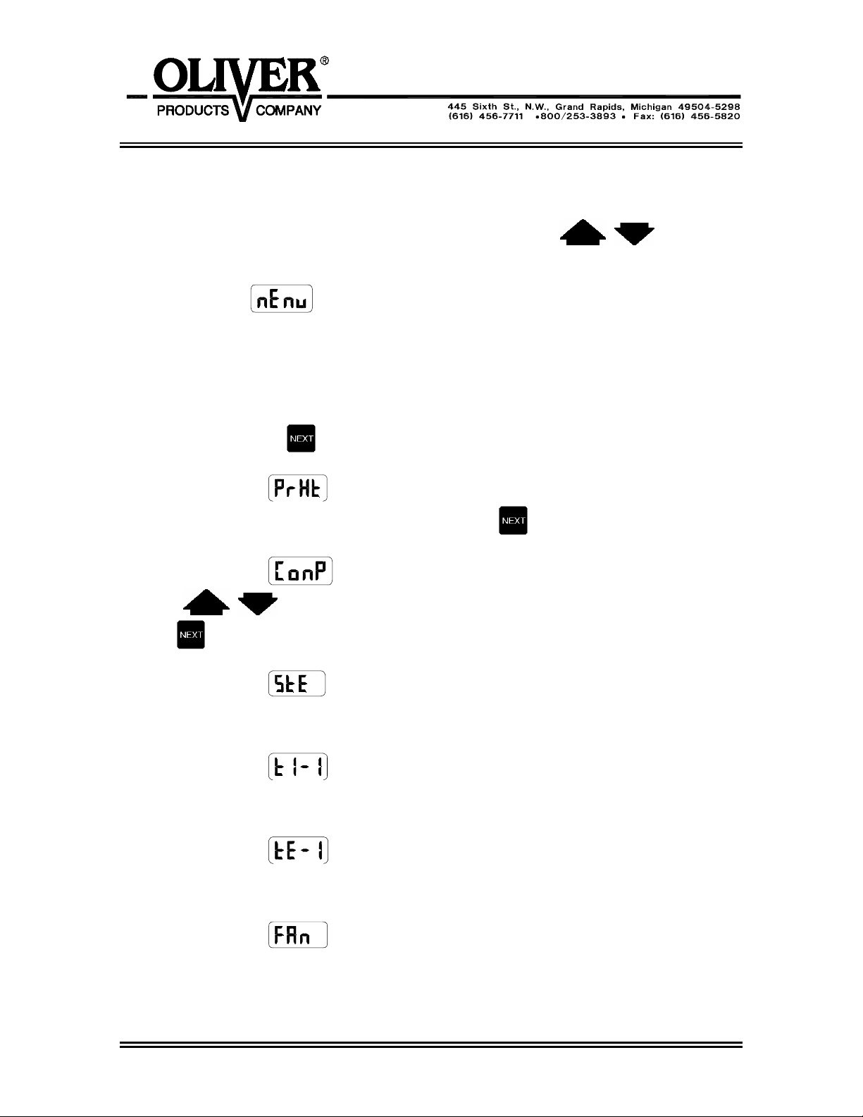
PROGRAMMING
The following are instructions for editing and creating a menu program.
1. Enter the Program Mode by pressing the up and down keys
simultaneously for 5 seconds.
2. Display shows
for MENU.
3. Key in the menu number you want to program (01-40), or use the up and down keys to
scroll.
Programs 01-20 can hold two stages.
Programs 21-40 hold one stage
4. Press the ‘next’ key
to edit/program the first parameter of the menu.
5. Display will show
enter the preheat temperature. Press the next key
for Pre-Heat. Use the up and down keys or the keypad to
to advance.
6. Display will show
keys
key
to adjust temperature Compensation to on or off. Press the next
to advance.
for Temperature Compensation. Use the up and down
7. Display will show
for steam. Use the up and down keys to adjust the steam
time between 0-30, C2, C3, and C4. C2 produces two cycles of 15 second steam. C3
produces three cycles etc. Press ‘next’ key to advance. (*)
8. Display will show
for stage 1 time. Use up and down keys or keypad to
enter the time in minutes and seconds. Press ‘next’ key to advance.
Example: Enter 1200 for twelve minutes and zero seconds.
9. Display will show
for stage 1 Temperature. Use up and down keys or
keypad to enter the Temperature between 250°F and 500°F. Press the ‘next’ key to
advance.
10. Display will show
for stage 1 fan. Use up and down keys to scroll between
Hi and Lo fans. Press ‘next’ key to advance.
0691S20006 5-1
 Loading...