

Oliver 4470 Owner's Manual
4470 Industrial Planer 25”
Owner’s Manual
Oliver Machinery M-4470 9/2017
Kent, WA 98032
info@olivermachinery.net Copyright 2003
www.olivermachinery.net

2

Warranty
Oliver makes every effort possible to assure that its equipment meets the highest possible standards of
quality and durability. All products sold by Oliver are warranted to the original customer to be free from
defects for a period of 2 (two) years on all parts, excluding electronics and motors, which are warranted
for 1 year. Oliver’s obligation under this warranty shall be exclusively limited to repairing or replacing (at
Oliver’s option) products which are determined by Oliver to be defective upon delivery F.O.B. (return
freight paid by customer) to Oliver, and on inspection by Oliver. This warranty does not apply to defects
due, directly or indirectly, to misuse, abuse, negligence, accidents, unauthorized repairs, alterations, lack
of maintenance, acts of nature, or items that would normally be consumed or require replacement due to
normal wear. In no event shall Oliver be liable for death, personal or property injury, or damages arising
from the use of its products.
Warning
Read this manual thoroughly before operating the machine. Oliver Machinery disclaims any liability for
machines that have been altered or abused. Oliver Machinery reserves the right to effect at any time,
without prior notice, those alterations to parts, fittings, and accessory equipment which they may deem
necessary for any reason whatsoever.
For More Information
Oliver Machinery is always adding new Industrial Woodworking products to the line. For complete, up-todate product information, check with your local Oliver Machinery distributor, or visit
www.olivermachinery.net
3

WARNING
Read this manual completely and observe all warning labels on the machine. Oliver Machinery has made
every attempt to provide a safe, reliable, easy-to-use piece of machinery. Safety, however, is ultimately
the responsibility of the individual machine operator. As with any piece of machinery, the operator must
exercise caution, patience, and common sense to safely run the machine. Before operating this product,
become familiar with the safety rules in the following sections.
• Always keep guards and covers in place and in proper operating condition.
1. If you are not properly trained in the use of a planer do not use until the proper training has been
obtained.
2. Read, understand and follow the safety instructions found in this manual. Know the limitations and
hazards associated with this machine.
3. Make certain that the machine frame is electrically grounded and that a ground lead is included in the
incoming electrical service. In cases where a cord and plug are used, make certain that the
grounding plug connects to a suitable ground. Follow the grounding procedure indicated in the
National Electrical Code.
4. Wear an approved safety shield, goggles, or glasses to protect eyes. Common eyeglasses are only
impact-resistant, they are not safety glasses.
5. Before operating the machine, remove tie, rings, watch and other jewelry and roll up sleeves above
the elbows. Remove all loose outer clothing and confine long hair. Protective type footwear should
be used. Where the noise exceeds the level of exposure allowed in Section 1910.95 of the OSHA
Regulations, use hearing protective devices. Do not wear gloves.
6. Keep the machine guards and covers in place for every operation. If any guards and covers are
removed for maintenance, DO NOT OPERATE the machine until the guards and covers are
reinstalled.
7. Keep the floor around the machine clean and free of scrap material, saw dust, oil and other liquids to
minimize the danger of tripping or slipping. Be sure the table is free of all scrap, foreign material and
tools before starting the planer. Make certain the work area is well lighted and that a proper exhaust
system is used to minimize dust. Use anti-skid floor strips on the floor area where the operator
normally stands and mark off machine work area. Provide adequate work space around the machine.
8. Maintain a balanced stance and keep your body under control at all times.
9. Before turning on machine, remove all extra equipment such as keys, wrenches, scraps, and cleaning
rags away from the machine.
10. Give the work you are doing your undivided attention. Looking around, carrying on a conversation,
and “horseplay” are careless acts that can result in serious injury.
11. Before performing any service, maintenance, adjustments or when changing knives disconnect the
machine from power source. A machine under repair should be RED TAGGED to show it should not
be used until the maintenance is complete.
4

12. Do not plane boards with loose knots, nails or any foreign material in the workpiece. Irregular, or
warped stock should be jointed first on one side before planing a parallel surface.
13. If the operator leaves the machine area for any reason, the planer should be turned "off" and the
cutterhead should come to a complete stop before their departure. In addition, if the operation is
complete, they should clean the planer and the work area. NEVER clean the planer with power "on"
and never use hands to clear sawdust and debris; use a brush or air hose.
14. Use only genuine Oliver Machinery factory authorized replacement parts and accessories; otherwise
the warranty and guarantee is null and void.
15. Do not use this Oliver planer for other than its intended use. If used for other purposes, Oliver
disclaims any real or implied warranty and holds itself harmless for any injury or damage which may
result from that use.
16. Do not operate this machine while under the influence of drugs, alcohol, or any medication.
17. This machine is deigned for planing wood products only. Do not use to plane any kind of substance
other then wood.
18. Never start the planer while a workpiece is in contact with the cutterhead or knives.
19. Always feed workpiece against the rotation of the cutterhead.
20. Some dust created by power sanding, sawing, grinding, drilling and other construction activities
contains chemicals known to cause cancer, birth defects or other reproductive harm. Some examples
of these chemicals are:
• Lead from lead-based paint.
• Crystalline silica from bricks and cement and other masonry products.
• Arsenic and chromium from chemically-treated lumber.
Your risk from these exposures varies, depending on how often you do this type of work. To reduce
your exposure to these chemicals, work in a well-ventilated area, and work with approved safety
equipment, such as those dust masks that are specifically designed to filter out microscopic particles.
Familiarize yourself with the following safety notices used in this manual:
CAUTION: (This means that if precautions are not heeded, it may result in minor or moderate injury
and/or possible machine damage)
WARNING: (This means that if precautions are not heeded, it could result in serious injury or possibly
even death).
5

Table of Contents Page Number
Warranty......................................................................................................................................................2
Warnings..................................................................................................................................................3-4
Table of Contents........................................................................................................................................5
Specifications...............................................................................................................................................5
Contents of the Shipping Container.............................................................................................................6
Uncrating the Machine.................................................................................................................................6
Machine Preparation and Setup..................................................................................................................6
Electrical Connections.................................................................................................................................7
Assembly.....................................................................................................................................................8
Control Panel...............................................................................................................................................8
Digital Controller.......................................................................................................................................8-9
Changing Units of Measure......................................................................................................................9
Calibrating the Display..............................................................................................................................9
Planing to a Specific Thickness................................................................................................................9
Raising and Lowering Table......................................................................................................................10
Adjusting Thickness Scale.........................................................................................................................10
Table Roller Adjustment.............................................................................................................................10
Changing Feed Rate..................................................................................................................................10
Table Stop.................................................................................................................................................10
Opening Hood............................................................................................................................................10
Setting / Changing Knives..........................................................................................................................11
Setup of Feed Rollers, Chipbreaker and Pressure Bar..............................................................................12
Anti-Kickback Fingers..........................................................................................................................13
Adjustment of In-Feed Roller...............................................................................................................13
Adjustment of Chipbreaker..................................................................................................................13
Adjustment of Pressure Bar.................................................................................................................14
Adjustment of Out-feed Rollers...........................................................................................................14
Helical Cutterhead.....................................................................................................................................15
V-Belt Adjustment......................................................................................................................................15
Adjusting Table Gibs..................................................................................................................................15
Adjusting Table Rollers..............................................................................................................................16
Maintenance..............................................................................................................................................16
Lubrication.................................................................................................................................................17
Troubleshooting.........................................................................................................................................18
Specifications
Stock No......................................................................................(10HP, 1Ph HSS Straight Knife) 4470.001
Stock No......................................................................................(15HP, 3Ph HSS Straight Knife) 4470.002
Stock No.........................................................................(10HP, 1Ph Carbide Helical Cutterhead) 4470.101
Stock No.........................................................................(15HP, 3Ph Carbide Helical Cutterhead) 4470.102
Maximum Stock Width (in.)........................................................................................................................25
Maximum Depth of Cut (in.)......................................................................................................................1/4
Maximum Stock Thickness (in.).............................................................................................................9-1/4
Minimum Stock Thickness (in.).................................................................................................................1/8
Minimum Stock Length (in.).......................................................................................................................10
Dust Port Diameter (in.)...............................................................................................................................5
Minimum CFM Required..........................................................................................................................900
Segmented Infeed Roller Diameter (in.).......................................................................................................3
Two Steel Outfeed Roller Diameter (in.)......................................................................................................3
Feed Speeds (FPM).................................................................................................................20, 25 and 30
Bed Rollers................................................................................................................................2, Adjustable
Table Size (L x W/in.).........................................................................................................................32 x 26
Cutterhead Diameter (in.)......................................................................................................................3-1/2
Number of Knives........................................................................................................................................4
Cutterhead Speed (RPM).....................................................................................................................4,800
Table Support.................................................................................................................................2-Column
Motor..........................................................................................................................10HP, 1Ph, 220V Only
........................................................................................................10HP, 3Ph, 220V/440V, Prewired 220V
Gross Weight (lbs.)...............................................................................................................................1,837
6
Oliver 4470 - 25” Industrial Planer
1. 25” Planer
Box 1
4. Leveling Pads
3. Hex Key Wrenches
3. Open End Wrenches
1. Screwdriver
2. Knife Setting Gauges
1. Knife Setting Gauge Shaft
4. E-Clips
1. Handle
Box 2
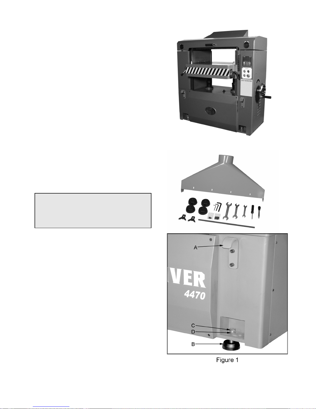
1. Dust Chute
8. Hex Head Screws M6x10
Uncrating the Machine
Retain all packaging materials in case it
becomes necessary to ship the machine to
another site.
Machine Preparation and Setup
WARNING!
The equipment used to lift this machine must
have a rated capacity at, or above the weight
of the planer. Failure to comply may cause
serious injury!
The planer can be lifted from over head using
slings and the four lifting hooks (A, Figure 1).
The planer must be positioned on a smooth,
level surface. Install the leveling pads (B, Figure
1) under the four corners of the planer.
Clean all rust protected surfaces with a
commercial solvent. Do not use acetone,
gasoline, lacquer thinner or any type of
flammable solvent, or a cleaner that may
damage paint. Cover cleaned surfaces with
WD-40 or a 20W machine oil.
Place a level on the table of planer and adjust
leveling bolts (C, Figure 1) until the machine is
resting level. Tighten the hex nuts (D, Figure 1)
against the base of the planer to keep the
leveling bolts from turning.
7

Electrical Connections
WARNING!
Electrical connections and wiring must be
done by a qualified electrician. The machine
must be properly grounded. Failure to
comply may cause serious injury!
This planer is available in both 1-Phase and 3Phase versions.
• Electrical Connections for a 3-Phase Unit
This planer is 3-Phase, 220V/440V pre-wired
220V. If you need to switch the planer from
220V to 440V have a qualified electrician make
the changes.
Make sure the voltage of your power supply
matches the specifications on the motor plate of
the machine.
1. Disconnect machine from power source!
2. Remove screws that secure the cover to
connection box.
3. Insert the power cable through strain relief,
and attach the wires to terminals.
4. Re-install connection box cover. With 3-
Phase power verify table raises when
pressing the “Table Up” button. If it does
not, disconnect machine from power source
and reverse any two incoming power leads.
5. When wiring is completed, tape all power
box joints to keep out dust.
• Electrical Connections for a 1-Phase Unit
This planer is 1-Phase, 220V only.
Make sure the voltage of your power supply
matches the specifications on the motor plate of
the machine.
1. Disconnect machine from power source!
2. Remove screws that secure the cover to
connection box.
3. Insert the power cable through strain relief,
and attach the wires to the terminals.
4. Re-install connection box cover.
5. When wiring is completed, tape all power
box joints to keep out dust.
8
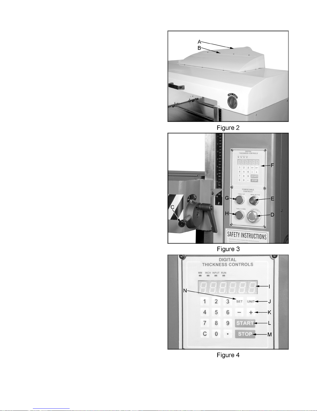
Dust Chute Assembly
Mount the dust chute (A, Figure 2) to the planer
hood with eight M6x10 hex head screws (B,
Figure 2). Make sure the dust collection system
has sufficient capacity and suction for your
planer. Always turn on the dust collection
system before starting the planer.
Table Roller Handle Assembly
Thread the handle (C, Figure 3) into the hub.
Control Panel
D. Emergency Stop Button: Stops all
functions of machine, but the planer still has
power. To reset rotate switch clockwise until
the button pops out.
E. Main Motor: Starts rotation of cutterhead.
Will not work if the “Emergency Stop” switch
is engaged, or hood is open.
F. Digital Thickness Controls: Displays and
controls table position, units, etc..
N. The “Set” button is used when calibrating or
setting the thickness scale.
G. Table Up: Raises the table. Note: Table
will contact the upper limit switch at about
5/8” and will automatically shut down. You
can continue to raise manually by using the
handwheel.
H. Table Down: Lowers the table. Note:
Table will contact the lower limit switch at
about 8-5/8” and will automatically shut
down. You can continue to lower manually
by using the handwheel.
Digital Controller
I. LED readout displays the thickness setting.
J. The digital thickness controls are capable of
operating and displaying in either inches, or
millimeters by pressing the “Units” button.
K. The “+” and “-“ buttons can be used to move
the table up or down without keying in an
exact numerical thickness value. Note: The
“-“ button raises the table to subtract from
workpiece thickness. The “+“ button lowers
the table.
L. “Start” button is used to begin table travel
after a numeric value has been keyed in.
M. The “Stop” button is used to stop the table
travel after it has started.
9

Changing Units of Measure
Press unit button (A, Figure 5) to toggle back
and forth between inches and millimeters.
Calibrating the Display
The following sections will describe the use of a
calibrating board. The calibrating board should
be made of a hardwood and have one side that
has been run through a jointer.
1. With the planer turned “OFF – cutterhead
NOT spinning”, place your calibrating board
jointed surface down on the table and slide it
into the machine.
2. Use the table “UP” button to raise the table
so that the in-feed roller is about 1/32"
above the calibrating board.
3. Remove calibrating board from planer and
turn the planer “ON”.
4. Use the table “UP” button to raise the table
about 0.1", as indicated by LED and run the
calibrating board through the planer.
5. Repeat Step 4 until the planer removes the
entire top surface of your calibrating board.
6. Measure the thickness of the board using a
pair of calipers.
7. Press the “SET” button (C, Figure 5) and
then type in the measured thickness from
step 6. Press the “SET” button again and
hold in until the decimal point stops blinking
(about three seconds).
Planing to a Specific Thickness
1. Measure thickest section of the workpiece.
2. Subtract the amount you wish to remove
from the current thickness of the workpiece.
3. Press the “SET” button and enter the
amount from step 2.
4. Press “START” button (D, Figure 5) to begin
the table movement up, or down until the set
value is achieved.
Note: Do not feed material through the
planer while the table is raising or lowering.
Fraction Decimal Metric
1/32 0.031 0.794
1/16 0.063 1.588
3/32 0.094 2.381
1/8 0.125 3.175
5/32 0.156 3.969
3/16 0.188 4.763
7/32 0.219 5.556
1/4 0.250 6.350
9/32 0.281 7.144
5/16 0.313 7.938
11/32 0.344 8.731
3/8 0.375 9.525
13/32 0.406 10.319
7/16 0.438 11.113
15/32 0.469 11.906
1/2 0.500 12.700
17/32 0.531 13.494
9/16 0.563 14.288
19/32 0.594 15.081
5/8 0.625 15.875
21/32 0.656 16.669
11/16 0.688 17.463
23/32 0.719 18.256
3/4 0.750 19.050
25/32 0.781 19.844
13/16 0.813 20.638
27/32 0.844 21.431
7/8 0.875 22.225
29/32 0.906 23.019
15/16 0.938 23.813
31/32 0.969 24.606
1 1.00 25.400
Figure 6
10
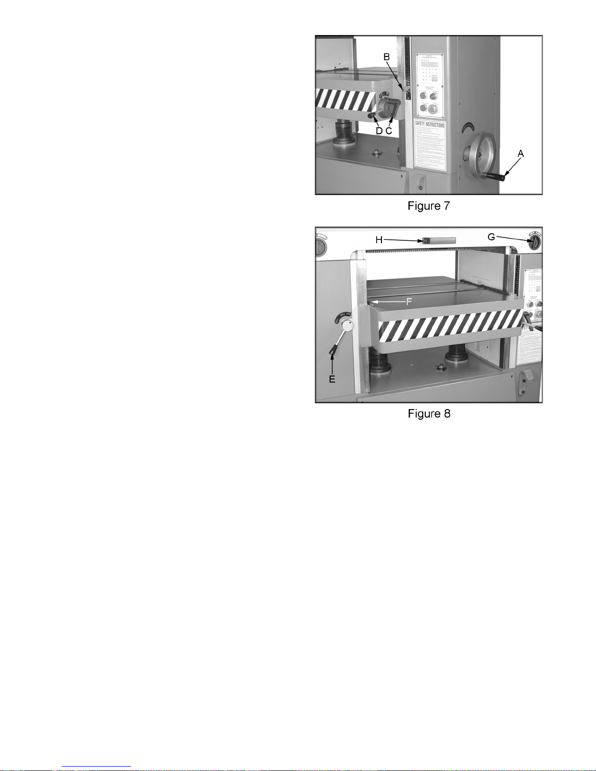
Raising and Lowering Table
Turn the handwheel (A, Figure 7) clockwise to
raise the table. One revolution equals 1/32” or
0.03”. Note: The handwheel is spring loaded.
Push in on the handwheel and rotate until the
pins engage the detents.
Adjusting Thickness Scale
1. Run a board through the planer and
measure the thickness of the planed board
with a pair of calipers.
2. Adjust the pointer (B, Figure 7) by loosening
the screw that holds it in place. Note: This
measurement should be the same as digital
readout.
Table Roller Adjustment
Loosen the handle (C, Figure 7) and move the
table rollers up, or down by raising, or lowering
the handle (D, Figure 7). When you reach the
desired position tighten the handle.
The rollers are usually set higher when planing
rough stock. When planing smooth stock the
table rollers should be set slightly above, or flush
with the table.
Changing Feed Rate
The planer has three selectable feed speeds
that feed stock at 20, 25 and 30 feet per minute.
To adjust speed, turn lever (E, Figure 8) until it
clicks into place. Change feed speed only
while the feed system is RUNNING!
Table Stop
The socket head cap screws (F, Figure 8) act as
a stop and prevent you from running the table
into the cutting and feeding assembly.
Opening Hood
Turn the locks (G, Figure 8) to open the hood.
The hood will open automatically. Use the
handle (H, Figure, 8) to shut the hood.
11
Setting / Changing Knives
WARNING!
Knives are extremely sharp. Be very careful
when handling knives. Failure to comply
may cause serious injury!
The Oliver 25” planer was designed to accept
25-1/8” x 1” x 1/8”) knives. Installing straight
knives accurately is an important step to achieve
a smooth finish. End to end, and knife to knife
adjustment must be accurate within .001". Use
a dial indicator if available to check results and
fine tune. Remove and replace the knife in one
slot before changing the next knife. Any knife
sharpening, or replacement should be done to
all four knives at the same time.
1. Disconnect machine from power source.
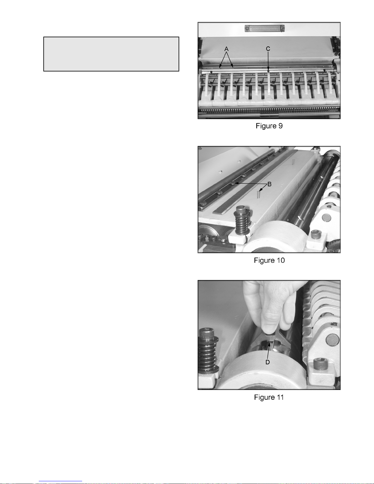
2. Open the hood, loosen ten locking bolts (A,
Figure 9) on the clamping block and remove
the knife. Remove and clean the clamping
block, and springs (B, Figure 10). Also
clean cutterhead knife slot before reinstalling the sharpened, or new knife.
3. Re-install the springs, knife and clamping
block, and just snug the ten locking bolts (A,
Figure 9). Note: You should still be able to
raise and lower the knife.
4. Notice that the knife does not rest at the
bottom of the knife slot. Instead, the knife
rests on three jack screws (C, Figure 9), and
two springs. These jack screws are used to
support and raise the knife.
5. Place the knife setting gauge (D, Figure 11)
on to the cutterhead as shown in Figure 11.
Use the jackscrew to raise the knife so that
the point just touches the raised portion of
the gauge.
6. Once knife is set to the proper height,
tighten two center locking bolts and, work
your way towards the ends until all bolts are
tight.
7. Re-check knife with the knife setting gauge
after tightening all of the locking bolts.
8. Repeat for the remaining three knives.
12
Setup of Feed Rollers, Chipbreaker and
Pressure Bar
WARNING!
Disconnect machine from the power source
before performing any adjustments or
maintenance. Failure to comply may cause
serious injury!
The planer comes set up from the factory and
shouldn’t need any adjustment.
If you find adjustment is necessary, follow the
below listed sections for setting the in-feed roller,
chipbreaker, pressure bar and outfeed rollers.
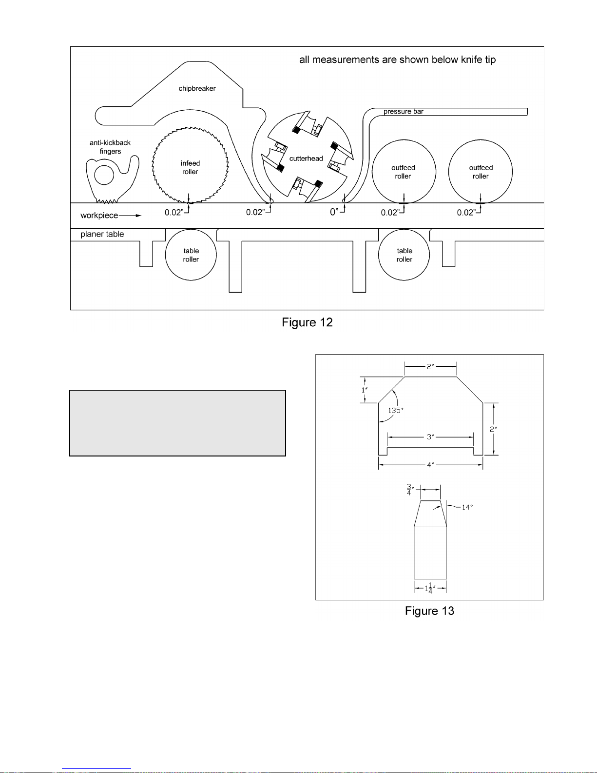
Make a hardwood block to the specifications in
drawing Figure 13. You can use this wood
gauge along with 0.02” feeler gauge to set the
planer up as shown in Figure 12.
Figure 12 shows setup for general planing
applications. Depending on the stock and
cutterhead you may find that a different setup
may work better for your particular planing
operation.
13
Anti-Kickback Fingers
Anti-kickback fingers help prevent stock from
being kicked out of the machine towards the
user. Keep the fingers clean and free from
sawdust, pitch gum, etc. so they operate
smoothly.
Adjustment of In-Feed Roller
The in-feed roller should be set 0.02” below the
lowest point of knife. Make sure the knives are
set properly see the “Setting / Changing Knives”
section on page 11 prior to making any
adjustments.
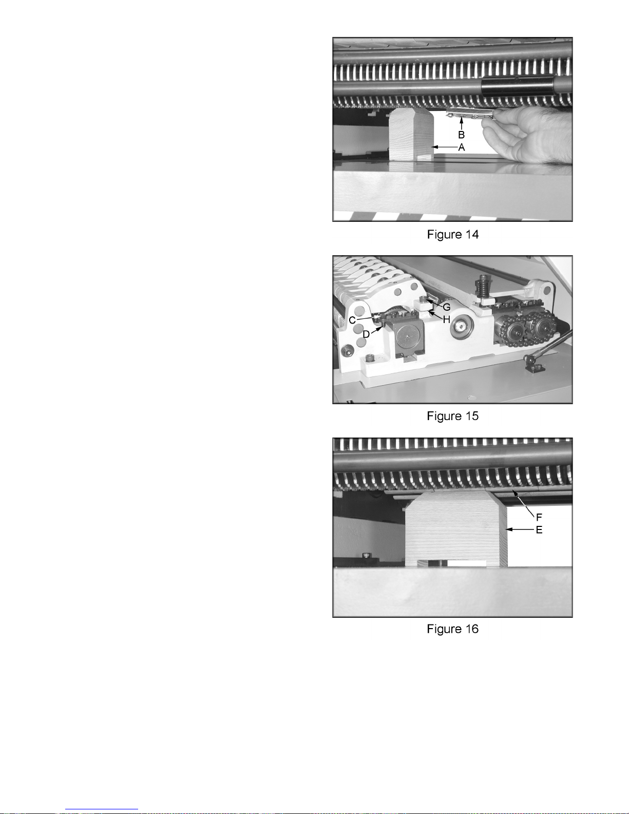
1. Disconnect machine from power source.
2. Place a hard wood gauge (A, Figure 14)
under a knife in cutterhead. Place a 0.02”
feeler gauge (B, Figure 14) on top of wood
block and raise table until feeler gauge
contacts the knife in its lowest position.
3. Remove feeler gauge and place wood block
under the left side of in-feed roller. The top
of wood gauge should just contact the infeed roller. If it doesn’t, loosen jam nut (C,
Figure 15) and turn the adjusting screw (D,
Figure 15) to raise, or lower the in-feed roller
until it contacts wood gauge. Repeat for
opposite side of the in-feed roller.
Adjustment of Chipbreaker
Chipbreaker should be set 0.02” below the
lowest point of knife. Make sure the knives are
set properly see the “Setting / Changing Knives”
section on page 11 prior to making any
adjustments.
1. Disconnect machine from power source.
2. Place a hard wood gauge (A, Figure 14)
under a knife in the cutterhead. Place a
0.02” feeler gauge (B, Figure 14) on top of
wood block and raise table until the gauge
contacts the knife in its lowest position.
3. Remove feeler gauge and place wood
gauge (E, Figure 16) under the left side of
chipbreaker (F, Figure 16). The top of the
wood gauge should just contact the
chipbreaker. If it doesn’t, remove the socket
head cap screw (G, Figure 15) and remove
washer (H, Figure 15), or replace with a
shim of proper thickness to raise, or lower
the chipbreaker until it contacts the wood
gauge. Repeat for opposite side of the
chipbreaker.
14
Adjustment of Pressure Bar
The pressure bar should be set even with the
lowest point of knife. Make sure the knives are
set properly see the “Setting / Changing Knives”
section on page 11 prior to making any
adjustments.
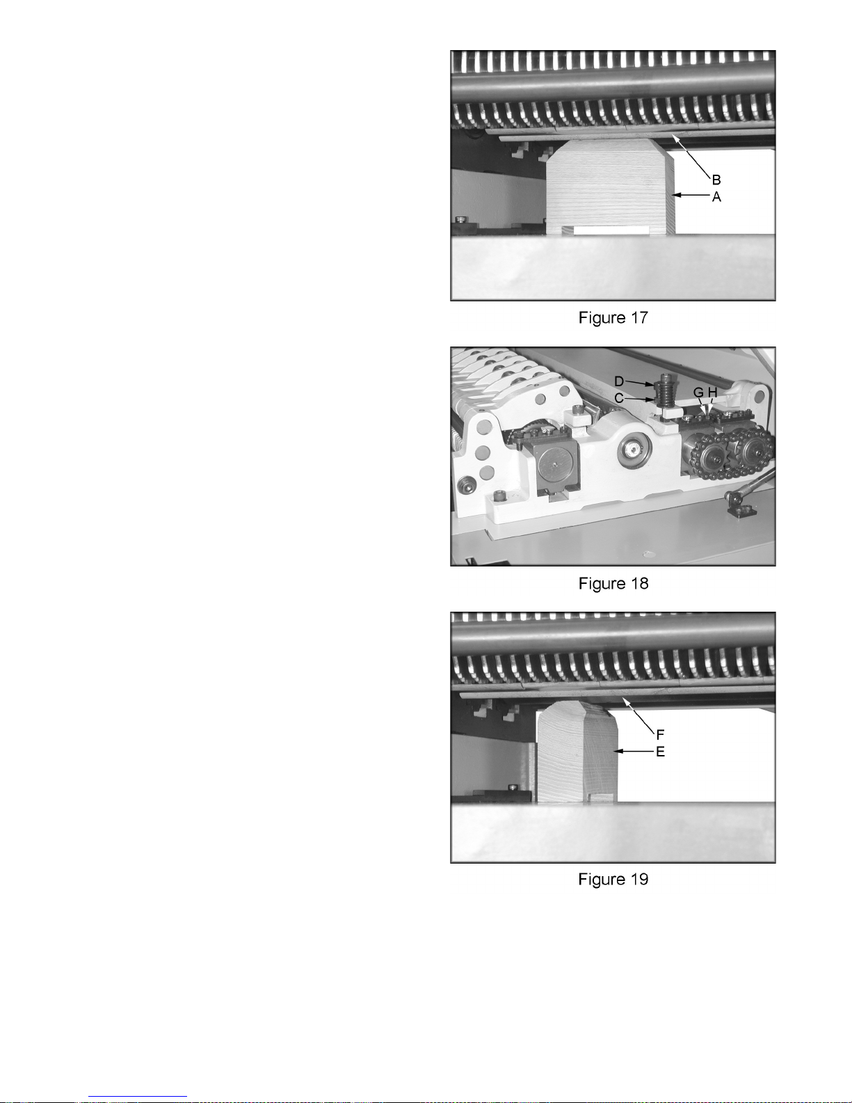
1. Disconnect machine from power source.
2. Place a hard wood gauge under a knife in
cutterhead. Raise table until wood gauge
contacts the knife in its lowest position.
3. Place wood block (A, Figure 17) under the
left side of pressure bar (B, Figure 17). The
top of wood gauge should just contact the
pressure bar. If it doesn’t, loosen jam nut
(C, Figure 18) and turn the adjusting screw
(D, Figure 18) to raise, or lower the pressure
bar until it contacts wood gauge. Repeat for
opposite side of the pressure bar.
Adjustment of Out-feed Rollers
The out-feed rollers should be set 0.02” below
the lowest point of knife. Make sure the knives
are set properly see the “Setting / Changing
Knives” section on page 11 prior to making any
adjustments.
1. Disconnect machine from power source.
2. Place a hard wood gauge (A, Figure 14)
under a knife in the cutterhead. Place a
0.02” feeler gauge (B, Figure 14) on top of
wood block and raise table until the gauge
contacts the knife in its lowest position.
3. Remove feeler gauge and place wood block
(E, Figure 19) under the left side of out-feed
roller (F, Figure 19). The top of wood gauge
should just contact the out-feed roller. If it
doesn’t, loosen jam nut (G, Figure 18) and
turn the adjusting screw (H, Figure 18) to
raise, or lower the out-feed roller until it
contacts wood gauge. Repeat for opposite
side of the out-feed roller.
4. Repeat for second out-feed roller
15
 Loading...