

Oliver 4420 Owner's Manual
4420 16” Planer
Owner’s Manual
Oliver Machinery M-4630 9/2019
Seattle, WA Copyright 2019
info@olivermachinery.net www.olivermachinery.net
1

Warranty
Oliver makes every effort possible to assure that its equipment meets the highest possible standards of
quality and durability. All products sold by Oliver are warranted to the original customer to be free from
defects for a period of 2 (two) years on all parts, excluding electronics and motors, which are warranted for 1
year. Oliver’s obligation under this warranty shall be exclusively limited to repairing or replacing (at Oliver’s
option) products which are determined by Oliver to be defective upon delivery F.O.B. (return freight paid by
customer) to Oliver, and on inspection by Oliver. This warranty does not apply to defects due, directly or
indirectly, to misuse, abuse, negligence, accidents, unauthorized repairs, alterations, lack of maintenance,
acts of nature, or items that would normally be consumed or require replacement due to normal wear. In no
event shall Oliver be liable for death, personal or property injury, or damages arising from the use of its
products.
Warning
Read this manual thoroughly before operating the machine. Oliver Machinery disclaims any liability for
machines that have been altered or abused. Oliver Machinery reserves the right to effect at any time, without
prior notice, those alterations to parts, fittings, and accessory equipment which they may deem necessary for
any reason whatsoever.
For More Information
Oliver Machinery is always adding new Industrial Woodworking products to the line. For complete, up-todate product information, check with your local Oliver Machinery distributor, or visit www.olivermachinery.net
.
PROP 65 NOTICE:
WARNING: Some dust created by power sanding, sawing, grinding, drilling, and other construction activities
contains chemicals known to the State of California to cause cancer and birth defects or other reproductive
harm.
Some examples of these chemicals are:
• lead from lead-based paints,
• crystalline silica from bricks and cement and other masonry products, and
• arsenic and chromium from chemically treated lumber.
Your risk from exposure to these chemicals varies, depending on how often you do this type of work. To
reduce
your exposure, work in a well-ventilated area and with approved safety equipment, such as dust masks that
are
specially designed to filter out microscopic particles. For more information go to www.P65Warnings.ca.gov.
All efforts have been made to ensure that the information in this catalog is accurate. However, Oliver
Machinery does not guarantee the accuracy of this information and reserves the right to change information in
this catalog without notification.
2

For Your Own Safety Read Instruction Manual Before Operating This Tool
Read this manual completely and observe all warning labels on the machine. This machine has made every
attempt to provide a safe, reliable, easy-to-use piece of machinery. Safety, however, is ultimately the
responsibility of the individual machine operator. As with any piece of machinery, the operator must exercise
caution, patience, and common sense to safely run the machine. Before operating this product, become
familiar with the safety rules in the following sections.
1. KEEP WORK AREA CLEAN. Cluttered areas and benches invite accidents.
2. DON'T USE IN DANGEROUS ENVIRONMENT. Don't use power tools in damp or wet locations,
or expose them to rain. Keep work area well lighted.
3. KEEP CHILDREN AWAY. All visitors should be kept safe distance from work area.
4. MAKE WORKSHOP KID PROOF with padlocks, master switches, or by removing starter keys.
5. USE RIGHT TOOL Don't force tool or attachment to do a job for which it was not designed.
6. WEAR PROPER APPAREL Do not wear loose clothing, gloves, neckties, rings, bracelets, or
other jewelry which may get caught in moving parts. Nonslip footwear is recommended. Wear
protective hair covering to contain long hair.
7. ALW AYS USE SAFETY GLASSES. Also use face or dust mask if cutting operation is dusty.
Everyday eyeglasses only have impact resistant lenses, they are NOT safety glasses.
8. SECURE WORK. Use clamps or a vise to hold work when practical. It's safer than using your
hand and it frees both hands to operate tool.
9. DON'T OVERREACH. Keep proper footing and balance at all times.
10. MAINTAIN TOOLS WITH CARE. Keep tools sharp and clean for best and safest performance.
Follow instructions for lubricating and changing accessories.
11. REDUCE THE RISK OF UNINTENTIONAL STARTING. Make sure switch is in off position
before plugging in.
12. USE RECOMMENDED ACCESSORIES. Consult the owner's manual for recommended
accessories. The use of improper accessories may cause risk of injury to persons.
13. CHECK DAMAGED PARTS. Before further use of the tool, a guard or other part that is
damaged should be carefully checked to determine that it will operate properly and perform its
intended function - check for alignment of moving parts, binding of moving parts, breakage of
parts, mounting, and any other conditions that may affect its operation.
A guard or other part that is damaged should be properly repaired or replaced.
14. DIRECTION OF FEED. Feed work into a blade or cutter against the direction of rotation of the
blade or cutter only.
15. NEVER LEAVE TOOL RUNNING UNATTENDED. TURN POWER OFF. Don't leave tool until it
comes to a complete stop.
16. Wear eye protection.
3

17. KEEP GUARDS IN PLACE and in working order.
18. REMOVE ADJUSTING KEYS AND WRENCHES. Form habit of checking to see that keys and
adjusting wrenches are removed from tool before turning it on.
19. DON'T FORCE TOOL It will do the job better and safer at the rate for which it was designed.
20. DISCONNECT TOOLS before servicing; when changing accessories, such as blades, bits,
cutters, and the like.
21. NEVER STAND ON TOOL. Serious injury could occur if the tool is tipped or if the cutting tool is
unintentionally contacted.
Your risk from these exposures varies, depending on how often you do this type of work. To
reduce your exposure to these chemicals, work in a well-ventilated area, and work with
approved safety equipment, such as those dust masks that are specifically designed to filter out
microscopic particles.
Familiarize yourself with the following safety notices used in this manual:
CAUTION: (This means that if precautions are not heeded, it may result in minor or moderate
injury and/or possible machine damage)
WARNING: (This means that if precautions are not heeded, it could result in serious injury or
possibly even death).
Grounding
This tool should be connected to a grounded metal permanent wiring system; or to a system having
an equipment-grounding conductor.
4

Table of Contents Page Number
Warranty ........................................................................................................................................................ 2
Warnings .................................................................................................................................................... 3-4
Table of Contents .......................................................................................................................................... 5
Specifications ................................................................................................................................................ 5
Receiving the planer ..................................................................................................................................... 6
Unpacking the Machine ................................................................................................................................. 6
Machine Preparation and Setup .................................................................................................................... 7
Assembly ....................................................................................................................................................... 7
Knife Replacement ........................................................................................................................................ 8
Switch safety lock .......................................................................................................................................... 8
Lubrication Schedule ..................................................................................................................................... 9
Depth of Cut ................................................................................................................................................ 10
Pulley Alignment.......................................................................................................................................... 10
V-belt Tensioning ........................................................................................................................................ 10
Feed Speed ................................................................................................................................................. 11
Return Rollers ............................................................................................................................................. 11
Feed Rollers ................................................................................................................................................ 11
Table Rollers ............................................................................................................................................... 12
Table Parallelism ......................................................................................................................................... 12
Feed Rollers and Chip breaker ................................................................................................................... 13
Adjustment of Chip Breaker .................................................................................................................. 14
Adjustment of Feed Rollers .................................................................................................................. 14
Digital Readout ............................................................................................................................................ 15
Parts ....................................................................................................................................................... 16-25
Specifications
Stock No. ........................................................................................ (5HP, 1Ph Helical Cutterhead) 4420.001
Maximum Stock Width (in.) ......................................................................................................................... 16
Maximum Depth of Cut (in.) ....................................................................................................................... 1/8
Maximum Stock Thickness (in.) .................................................................................................................... 6
Minimum Stock Thickness (in.) .................................................................................................................. 1/8
Minimum Stock Length (in.) .......................................................................................................................... 6
Dust Port Diameter (in.) ................................................................................................................................ 4
Minimum CFM Required ........................................................................................................................... 600
Feed Speeds (FPM) ........................................................................................................................ 16 and 20
Bed Rollers ................................................................................................................................. 2, Adjustable
Overall Dimension When Assembled (L x W x H in.) ............................................................ 48 x 28 x 43-1/2
Cutterhead Diameter (in.) ........................................................................................................................ 2-7/8
Number of Knives ........................................................................................................................................ 90
Cutterhead Speed (RPM) ........................................................................................................................ 4800
Motor ............................................................................................................................. 5HP, 1Ph, 220V Only
Gross Weight (lbs.).................................................................................................................................... 675
5

16” PLANER
Thank you for choosing this planer.
This unit is carefully tested and inspected before
shipment and if properly used and maintained, will
provide you with many years of reliable service. To
ensure optimum performance and trouble free
operation a reasonable amount of care and attention is
required. To get the most from your new planer, please
take the time to read this manual before assembling,
installing and operating the unit.
UNPACKING AND CLEANING
To ensure maximum performance from your 16" planer,
clean it properly; and install it accurately before use. As
soon as you receive the planer, we recommend you
follow these procedures:
1. Remove the contents of the shipping container.
2. Report damage, if any to your local distributor.
3. Clean all rust protected surfaces with a mild solvent
or kerosene. Do not use lacquer thinner; paint thinner,
or gasoline. These will damage painted surfaces.
4. To prevent rust, apply a light coating of paste wax to
surface.
CARRIAGE
The planer has four lifting handles (A), that can be
pulled out when needed. (Fig.1)
USING A SLING
When using a sling to carry machine, lifting handles
must be pulled out (Fig.2). Try keeping sling parallel to
machine and hold steady.
MAGNETIC CONTACTOR CURCUIT
FI G. 3
- Single phase motor
- Power source: A,C in put
- Motor source : A,C, out put
- Grounding: D
Fig. 1
Fig. 2
Fig. 3
6
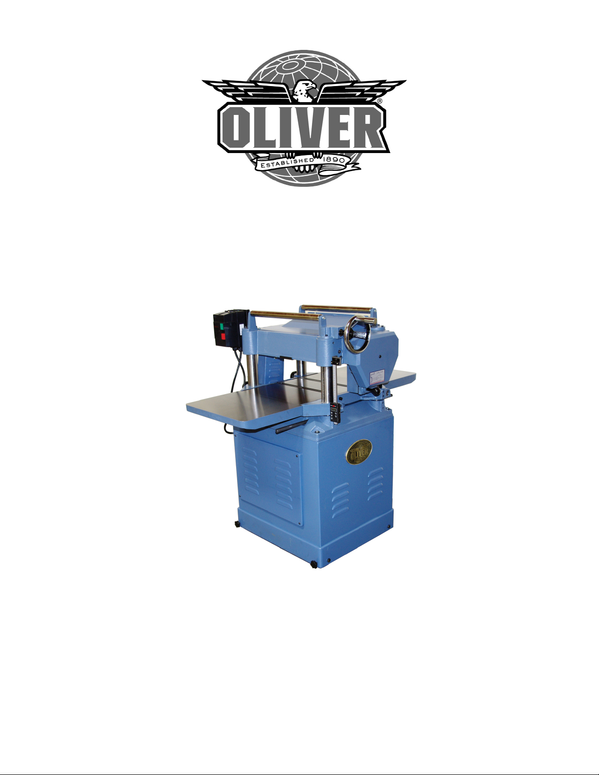
EXTENSION TABLE ASSEMBLY
Ask another person to provide assistance to hold an
extension table. Bolt the table to the machine using the
supplied bolts then place a straight edge on the table
as shown if Fig. 4. If they are not aligned, loosen the
bolts and adjust the alignment screws accordingly and
the tighten back the main bolts.
WARNING: Always disconnect the machine from
the power source before assembly or any servicing
to the machine.
DUST CHUTE ASSEMBLY
Mount the dust chute to the planer hood with hex head
screws and washers (A) & (B). Make sure the dust
collection system has sufficient capacity and
suction for your planer. Always turn on the
dust collection system before starting the planer.
Figure 5
Fig. 4
CONSTRUCTING GAUGE BLOCK
Your Oliver planer has been adjusted at the factory and
should not need adjustment. Typically poor
performance can be attributed to dull knives however if
the knives are in good order it may be time to check the
machine. Construct a guage block as shown if Fig. 6.
Machine adjustments are found further along in this
manual.
Fig. 5
Fig. 6
7
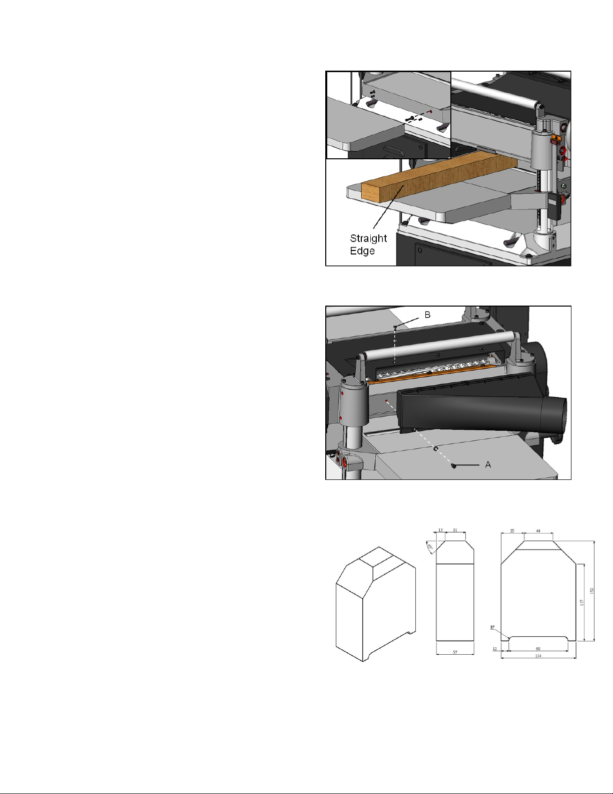
Knife Replacement
Knife inserts are dangerously
sharp. Use extreme caution when inspecting,
removing, or replacing knife inserts.
The knife inserts on the Jointer are four-sided. When
dull, simply remove each insert, rotate it 90° for a fresh
edge, and re-install it. No further adjustment is
necessary. Use the two provided torx wrench to
remove the knife insert screw. Use one of the torx
wrenches to help hold the cutterhead in Position, and
the other to remove the screw. See Fig. 7. It is
advisable to rotate all inserts at the same time to
maintain consistent cutting. However, if one or more
knife inserts develops a nick, rotate only those inserts
that are affected.
Each knife insert has an etched reference mark so you
can keep track of the rotations.
IMPORTANT:
clean saw dust from the screw, the insert, and the
cutterhead platform. Dust accumulation between
these elements can prevent the insert from seating
properly, and may affect the quality of the cut.
Before installing each screw, lightly coat the screw
threads with machine oil and wipe off any excess.
Securely tighten each screw which holds the knife
inserts before operating the jointer! Loose inserts
can be propelled at high speed from a rotating
cutterhead, causing injury.
When removing or rotating inserts,
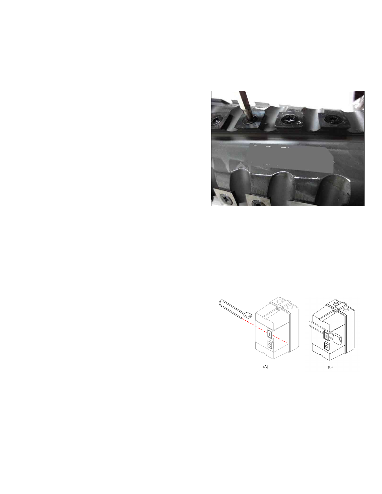
SWITCH
The planer is equipped with magnetic
switch that will accept a safety padlock
(not included). See Fig. 8. To safeguard
your machine from unauthorized operation
and accidental starting by young children,
the use of a padlock is required.
Fig. 7
Fig. 8
8
 Loading...