

Oliver 4230 Owner's Manual

4230 8” Jointer
Owner’s Manual
Oliver Machinery M-4230 10/2007
Seattle, WA
info@olivermachinery.net Copyright 2003
www.olivermachinery.net

Warranty
Oliver makes every effort possible to assure that its equipment meets the highest possible standards of
quality and durability. All products sold by Oliver are warranted to the original customer to be free from
defects for a period of 2 (two) years on all parts, excluding electronics and motors, which are warranted
for 1 year. Oliver’s obligation under this warranty shall be exclusively limited to repairing or replacing (at
Oliver’s option) products which are determined by Oliver to be defective upon delivery F.O.B. (return
freight paid by customer) to Oliver, and on inspection by Oliver. This warranty does not apply to defects
due, directly or indirectly, to misuse, abuse, negligence, accidents, unauthorized repairs, alterations, lack
of maintenance, acts of nature, or items that would normally be consumed or require replacement due to
normal wear. In no event shall Oliver be liable for death, personal or property injury, or damages arising
from the use of its products.
Warning
Read this manual thoroughly before operating the machine. Oliver Machinery disclaims any liability for
machines that have been altered or abused. Oliver Machinery reserves the right to effect at any time,
without prior notice, those alterations to parts, fittings, and accessory equipment which they may deem
necessary for any reason whatsoever.
For More Information
Oliver Machinery is always adding new Industrial Woodworking products to the line. For complete, up-todate product information, check with your local Oliver Machinery distributor, or visit
www.olivermachinery.net
2

WARNING
Read this manual completely and observe all warning labels on the machine. Oliver Machinery has made
every attempt to provide a safe, reliable, easy-to-use piece of machinery. Safety, however, is ultimately
the responsibility of the individual machine operator. As with any piece of machinery, the operator must
exercise caution, patience, and common sense to safely run the machine. Before operating this product,
become familiar with the safety rules in the following sections.
• Always keep guards in place and in proper operating condition.
• Never reach around or under the jointer.
1. If you are not properly trained in the use of a jointer do not use until the proper training has been
obtained.
2. Read, understand and follow the safety instructions found in this manual. Know the limitations and
hazards associated with this machine.
3. Electrical grounding: Make certain that the machine frame is electrically grounded and that a
ground lead is included in the incoming electrical service. In cases where a cord and plug are used,
make certain that the grounding plug connects to a suitable ground. Follow the grounding procedure
indicated in the National Electrical Code.
4. Eye safety: Wear an approved safety shield, goggles, or glasses to protect eyes. Common
eyeglasses are only impact-resistant, they are not safety glasses.
5. Personal protection: Before operating the machine, remove tie, rings, watch and other jewelry and
roll up sleeves above the elbows. Remove all loose outer clothing and confine long hair. Protective
type footwear should be used. Where the noise exceeds the level of exposure allowed in Section
1910.95 of the OSHA Regulations, use hearing protective devices. Do not wear gloves.
6. Guards: Keep the machine guards in place for every operation for which they can be used. If any
guards are removed for maintenance, DO NOT OPERATE the machine until the guards are
reinstalled.
7. Work area: Keep the floor around the machine clean and free of scrap material, saw dust, oil and
other liquids to minimize the danger of tripping or slipping. Be sure the table is free of all scrap,
foreign material and tools before starting to use the machine. Make certain the work area is well
lighted and that a proper exhaust system is used to minimize dust. Use anti-skid floor strips on the
floor area where the operator normally stands and mark off machine work area. Provide adequate
work space around the machine.
8. Jointer position: Position the jointer so that in case of material kick back the flying piece will not
injure workers.
9. Material condition: Do not attempt to joint boards with loose knots or with nails or other foreign
material.
10. Operator: Always use push blocks. Maintain a balanced stance and keep your body under control
at all times.
11. Before starting: Before turning on machine, remove all extra equipment such as keys, wrenches,
scraps, and cleaning rags away from the machine and off the table.
3

12. Careless acts: Give the work you are doing your undivided attention. Looking around, carrying on a
conversation, and “horseplay” are careless acts that can result in serious injury.
13. Disconnect all power sources: Before performing any service, maintenance, adjustments or when
changing blades. A machine under repair should be RED TAGGED to show it should not be used
until the maintenance is complete.
14. Job completion: If the operator leaves the machine area for any reason, the jointer should be
turned "off" and the cutter head should come to a complete stop before leaving.
15. Replacement parts: Use only genuine Oliver Machinery factory authorized replacement parts and
accessories; otherwise the warranty and guarantee are null and void.
16. Misuse: Do not use this Oliver jointer for other than its intended use. If used for other purposes,
Oliver disclaims any real or implied warranty and holds itself harmless for any injury or damage which
may result from that use.
17. Drugs, alcohol and medication: Do not operate this machine while under the influence of drugs,
alcohol, or any medication.
18. This machine is designed for planing wood products only. Do not use to cut any kind of metal or
substance other then wood.
19. Never start the jointer while a workpiece is in contact with the blade.
20. Raise or lower the tables only when the machine has been turned “off” and the cutter head has
come to a complete stop.
21. Make sure the cutter head is running in the proper direction. The knives should be turning toward the
infeed table.
22. Health hazards: Some dust created by power sanding, sawing, grinding, drilling and other
construction activities contains chemicals known to cause cancer, birth defects or other reproductive
harm. Some examples of these chemicals are:
• Lead from lead-based paint.
• Crystalline silica from bricks and cement and other masonry products.
• Arsenic and chromium from chemically-treated lumber.
Your risk from these exposures varies, depending on how often you do this type of work. To reduce
your exposure to these chemicals, work in a well-ventilated area, and work with approved safety
equipment, such as those dust masks that are specifically designed to filter out microscopic particles.
Familiarize yourself with the following safety notices used in this manual:
CAUTION: (This means that if precautions are not heeded, it may result in minor or moderate injury
and/or possible machine damage)
WARNING: (This means that if precautions are not heeded, it could result in serious injury or possibly
even death).
4

Table of Contents Page Number
Warranty......................................................................................................................................................2
Warnings..................................................................................................................................................3-4
Table of Contents........................................................................................................................................5
Specifications...............................................................................................................................................5
Uncrating the Machine.................................................................................................................................6
Contents......................................................................................................................................................6
Machine Preparation and Setup............................................................................................................6-8
Control panel and magnetic starter..............................................................................................................7
V-Belts.........................................................................................................................................................7
Handwheels.................................................................................................................................................8
Dust Collection.............................................................................................................................................8
Electrical Connections.................................................................................................................................8
Blade guard.................................................................................................................................................8
Fence Operation........................................................................................................................................9
Fence Legend..............................................................................................................................................9
Adjustment of the 90 Degree Stop...............................................................................................................9
Fence Operation..........................................................................................................................................9
Knives.......................................................................................................................................................10
Knife Replacement.....................................................................................................................................10
Adjusting the Outfeed Table......................................................................................................................10
Operation..................................................................................................................................................11
Hand Safety and Placement......................................................................................................................11
Jointing......................................................................................................................................................11
Direction of the grain..................................................................................................................................11
Edging........................................................................................................................................................11
Facing........................................................................................................................................................12
Beveling.....................................................................................................................................................12
Rabbeting..................................................................................................................................................12
Adjusting the Infeed Table Height..............................................................................................................13
Maintenance.............................................................................................................................................13
V-Belts.......................................................................................................................................................13
Lubrication.................................................................................................................................................13
Knives........................................................................................................................................................13
Table Leveling...........................................................................................................................................13
Troubleshooting.......................................................................................................................................14
Specifications
Model No...............................................................................................................................................4230
Motor...............................................................................................................................2HP, 1PH, 220 Volt
Full load amps...........................................................................................................................................12
Infeed Table Travel (in.)............................................................................................................................1/2
Cutterhead speed (RPM).......................................................................................................................5500
Number of Knives......................................................................................................................................54
Rabbeting Capacity (in.)...........................................................................................................................1/2
Dust Port Diameter (in.)...............................................................................................................................4
Table Dimensions (L x W/in.)...................................................................................................74-7/8 x 9-1/4
Table Height (In.).................................................................................................................................30-1/2
Fence Dimensions (L x H/in.)...............................................................................................................38 x 4
Fence Tilts (deg.)................................................................................................................................90 - 45
Positive Stops (deg.)......................................................................................................................90 and 45
Overall Dimensions....................................................................................................................75 x 25 x 40
Gross Weight (lbs.)..................................................................................................................................572
CFM...........................................................................................................440CFM at 4500FPM air velocity
5
Oliver 4230 – 8” Jointer
Uncrating the Machine
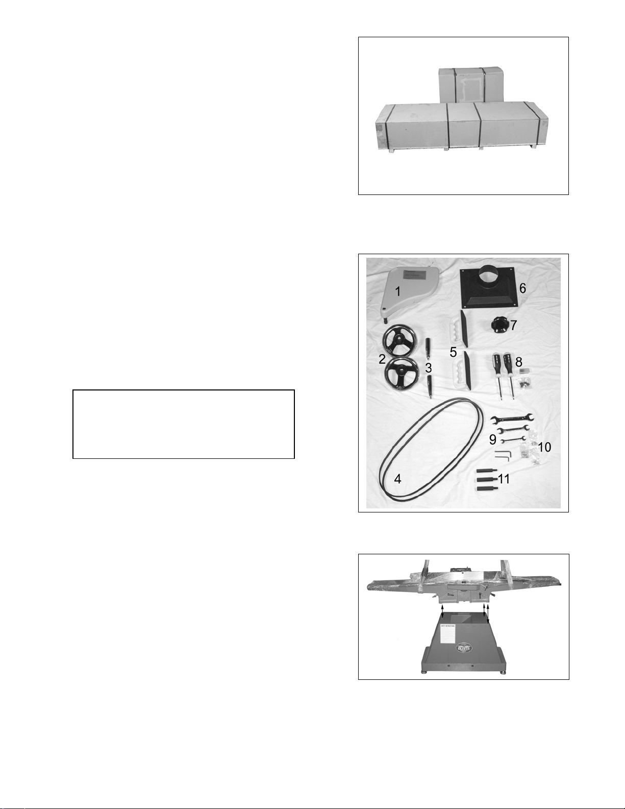
The machine should arrive as show in Figure 1.
Uncrate the machine and inspect the unit for
signs of shipping damage. If damage is found,
contact your dealer immediately. Unbolt the
machine from the pallet. Retain all packaging
materials in case it becomes necessary to ship
the machine to another site.
Contents: (Figure 2)
1. Blade guard
2. Two in/outfeed table hand wheels
3. Two speed handles for hand wheels
4. Two V-belts
5. Two push handles
6. Dust collection flange
7. Fence width adjustment knob
8. Two torx screw drivers, extra
knives and screws.
9. Tools; three wrenches and two
allen keys.
10. Three hardware packets.
11. Jointer to stand mounting bolts.
Figure 1
Machine Preparation and Setup
WARNING!
The equipment used to lift this machine must
have a rated capacity at, or above the weight
of the jointer. Failure to comply may cause
serious injury!
Mount the jointer top to the stand as seen in
Figure 3. Line up the holes then lower the
jointer onto the stand. Use the three, jointer to
stand mounting bolts (#11 of Figure 2), to secure
the jointer to the stand. The jointer must be
positioned on a smooth, level surface. The area
must be well lit and have plenty of room to
maneuver with large pieces of wood.
Level the jointer front to back and side to side
using a level placed on the table. Adjust the
leveling feet as needed but make sure the jointer
is stable before being placed into service.
Clean all rust protected surfaces with a
commercial solvent. Do not use acetone,
gasoline, lacquer thinner or any type of
flammable solvent, or a cleaner that may
damage paint. Cover cleaned surfaces with
WD-40 or a 20W machine oil.
Figure 2
Figure 3
6
Machine Preparation and Setup (Cont.)
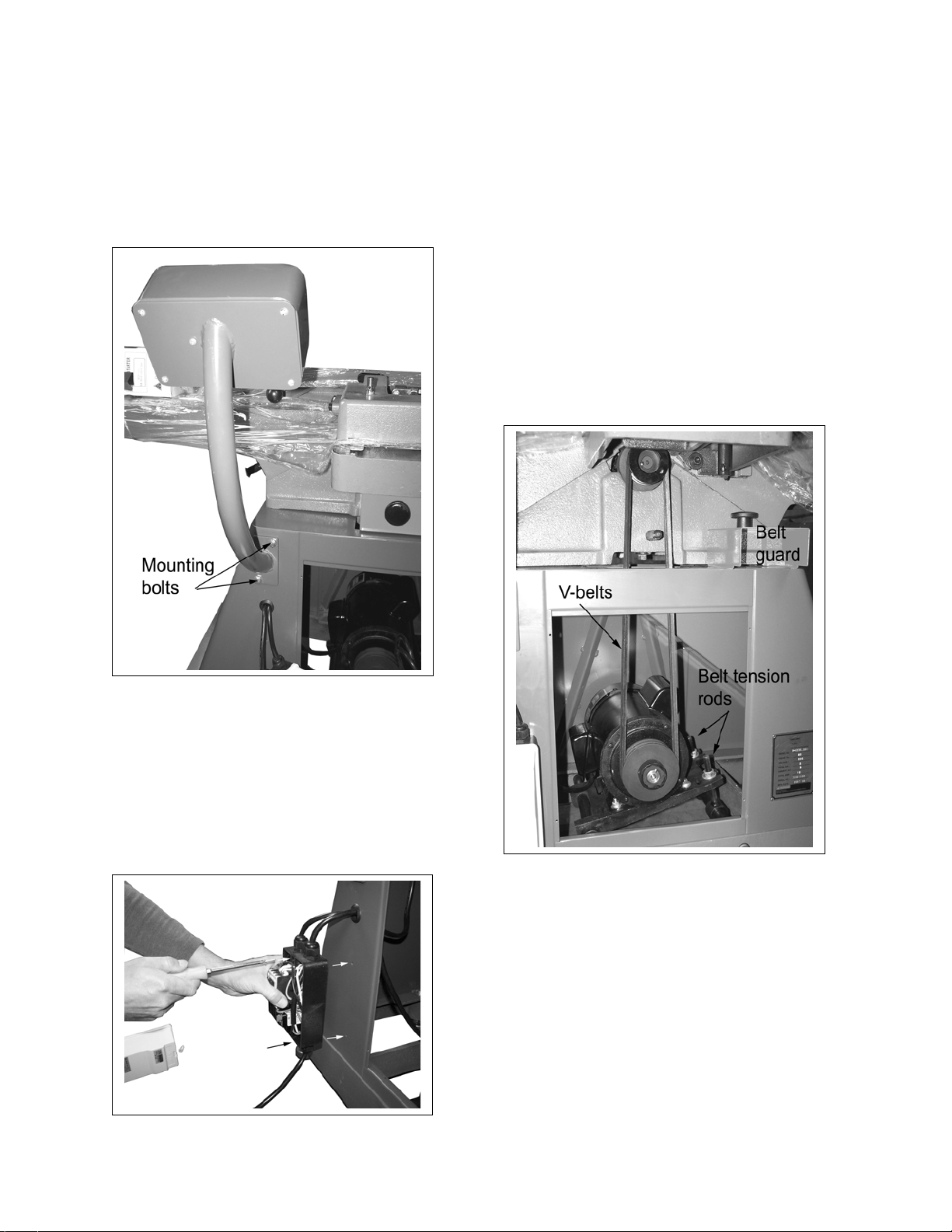
Control Panel and Magnetic Starter
Remove the control box and magnetic starter
from the jointer stand. Mount the control box to
the back of the stand as shown in Figure 4 using
the supplied 12mm hex bolts.
V-Belts
Remove the belt guard and set aside as shown
in Figure 6. Place the belts over the cutterhead
and motor pulley. It may be necessary to loosen
the nuts of the belt tension rods in order to
stretch the belts over the pulleys. Once in place
adjust the nuts of the belt tension rods to give
approximately ½” deflection midway along the
belts using finger pressure. Re-install the belt
guard.
After approximately 20 hours of operation recheck the tension on the belts and adjust if
necessary.
Figure 4
Remove the lid from the magnetic starter and
mount the switch to the back of the jointer stand
using the two machine screws as shown in
Figure 5. Insert the screws through the two
large threaded holes in which the large plastic
screws secure the cover. Once in place, reinstall the lid.
Figure 5
Figure 6
7
 Loading...