

Page 1

OKIPAGE24DX / OKIPAGE24dx
LED Page Printer
Maintenance Manual
ODA/ OEL/ INT
1998.12.22 DRAFT Version
40930701TH DRAFT Version 1 / 237
Page 2

PREFACE
This maintenance manual describes the field maintenance methods for OKIPAGE24DX/OKIPAGE24dx.
This manual is written for use by maintenance personnel. Note, however, that the user should refer to
the USER’S MANUAL for methods of handling and operating the equipment.
40930701TH DRAFT Vesion 2 /
Page 3

CONTENTS
1. CONFIGURATION....................................................................................... 7
1.1 System Configuration................................................................................................. 7
1.2 Printer Configuration .................................................................................................. 8
1.3 Optional Configuration ............................................................................................... 9
1.4 Specification............................................................................................................... 11
1.5 Safety Standards ....................................................................................................... 13
1.5.1 Certification label .......................................................................................... 13
1.5.2 Warning label................................................................................................ 13
2. OPERATION DESCRIPTION ...................................................................... 14
2.1 Main Control Board (BOARD-FFF) ............................................................................ 16
2.2 Power Supply Unit ..................................................................................................... 20
2.3 Electro-photographic Process.................................................................................... 22
2.3.1 Electro-photographic process mechanism ................................................... 22
2.3.2 Electro-photographic process....................................................................... 24
2.4.3 Process operation descriptions .................................................................... 28
2.3.4 Revision of LED Head Illumination ............................................................... 39
2.4 Paper Jam Detection ................................................................................................. 47
2.5 Cover Open................................................................................................................ 48
2.6 Toner Low Detection.................................................................................................. 49
2.7 Stacker-full Detection................................................................................................. 51
2.8 Page Size Detection .................................................................................................. 51
3. PARTS REPLACEMENT............................................................................. 52
3.1 Precautions for Parts Replacement ........................................................................... 52
3.2 Parts Layout............................................................................................................... 54
3.3 How to Change Parts................................................................................................. 58
3.3.1 Face -up Stacker Assy ................................................................................. 59
3.3.2 Contact Assy ................................................................................................ 60
3.3.3 DC Fan Motor ............................................................................................... 61
3.3.4 OP Panel Assy ............................................................................................. 62
3.3.5 Board-FFF .................................................................................................... 63
3.3.6 Stacker Assy, Damper Arm, Cover Rear..................................................... 64
3.3.7 Sensor Stacker Full ...................................................................................... 65
3.3.8 Cable cover (guide film)................................................................................ 66
3.3.9 Damper......................................................................................................... 67
3.3.10 Feeder Unit-Front......................................................................................... 68
3.3.11 Roller Assy-Regist........................................................................................ 69
3.3.12 Motor -Main .................................................................................................. 70
3.3.13 Guide Assy-Eject.......................................................................................... 72
3.3.14 Heat Assy..................................................................................................... 73
3.3.15 Roller feed (C) ............................................................................................. 74
3.3.16 Roller Assy-BK ............................................................................................. 75
3.3.17 Roller Assy-Feed.......................................................................................... 76
3.3.18 LED Head..................................................................................................... 77
3.3.19 Paper cassette, ROLLER Ass-Feed, ROLLER-Assy-Hoppibg..................... 78
3.3.20 Frame Assy-Separation................................................................................ 79
3.3.21 Transfer Roller/TR Gear/TR Bearing............................................................ 80
3.3.22 EP lock shaft................................................................................................. 81
3.3.23 LEVER Assy- Out Sensor............................................................................. 82
3.3.24 Toner sensor lever........................................................................................ 83
3.3.25 Paper sensor lever ....................................................................................... 84
3.3.26 Inlet sensor lever.......................................................................................... 85
40930701TH DRAFT Vesion 3 /
Page 4

3.3.27 Power supply unit......................................................................................... 86
3.3.28 Lever-Paper end & Lever-Paper near end ................................................... 87
3.3.29 Guide Assy-Cassette (L) .............................................................................. 89
3.3.30 Guide Assy-Cassette (R).............................................................................. 90
3.3.31 Removing/Installing Duplex Unit................................................................... 92
3.3.32 Board-LEX.................................................................................................... 94
3.3.33 Connector (IMSA-9714N-14A) ..................................................................... 95
3.3.34 Photo Sensor................................................................................................ 96
3.3.35 SOLENOID Assy.......................................................................................... 97
3.3.36 Motor ............................................................................................................ 98
4. ADJUSTMENT............................................................................................. 99
4.1 Maintenance Modes And Functions........................................................................... 99
4.1.1 User maintenance mode .............................................................................. 101
4.1.2 System maintenance mode.......................................................................... 105
4.1.3 Engine maintenance mode........................................................................... 107
4.1.4 EEPROM initialization .................................................................................. 111
4.2 Adjustment When Replacing A Part........................................................................... 112
4.2.1 Resetting the fuser counter .......................................................................... 113
4.2.2 Destination setting ........................................................................................ 114
4.2.3 Setting of LED head drive time..................................................................... 115
115
5. PERIODIC MAINTENANCE ........................................................................ 118
5.1 Periodic Replacing Part ............................................................................................. 118
5.2 Cleaning..................................................................................................................... 118
5.2.1 Cleaning of LED lens array........................................................................... 118
5.2.2 Cleaning the Plastic Film .............................................................................. 119
6. TROUBLESHOOTING PROCEDURES ...................................................... 120
6.1 Troubleshooting Tips ................................................................................................. 120
6.2 Points to Check before Correcting Image Problems.................................................. 120
6.3 Tips for Correcting Image Problems .......................................................................... 120
6.4 Preparation for Troubleshooting ................................................................................ 121
6.5 Troubleshooting Flow................................................................................................. 121
6.5.1 LCD status message/trouble list................................................................... 121
6.5.2 LCD message troubleshooting ..................................................................... 133
6.5.3 Image troubleshooting .................................................................................. 154
7. WIRING DIAGRAM..................................................................................... 165
7.1 Interconnect Signal Diagram...................................................................................... 165
7.2 PCB Layout................................................................................................................ 167
7.3 Resistance Check ...................................................................................................... 170
7.4 Program/Font ROM Location ..................................................................................... 172
8. PARTS LIST ................................................................................................ 174
40930701TH DRAFT Vesion 4 /
Page 5

APPENDIX A CENTRONICS PARALLEL INTERFACE .................................... 185
APPENDIX B RS-232C SERIAL INTERFACE ................................................... 189
APPENDIX C SECOND/ THIRD PAPER FEEDER MAINTENANCE................. 191
1. OUTLINE ................................................................................................................... 191
1.1 Functions ...................................................................................................... 191
1.2 Appearance and Parts Name ....................................................................... 191
2. Description of operartion............................................................................................ 192
2.1 Driving Mechanism....................................................................................... 192
2.2 Hopper Mechanism ...................................................................................... 194
3. PARTS REPLACEMENT ........................................................................................... 195
3.1 Precautions Concerning Parts Replacement................................................ 195
3.2 Parts Layout ................................................................................................. 197
3.3 Parts Replacement Methods ........................................................................ 198
3.3.1 Roller assy hopping, Roller assy feed............................................. 199
3.3.2 Cover front assy .............................................................................. 200
3.3.3 Board-BBB ...................................................................................... 201
3.3.4 Lever paper end, Lever paper near end.......................................... 202
3.3.5 Motor ............................................................................................... 203
3.3.6 Connector (IMSA-9714N-14B), Connector (IMSA-9714N-14A)...... 204
3.3.7 Frange pulley, pulley Idle, Mini pitch belt, Plate Earth shaft,
Gear double, Tray switch assy .................. 205
3.3.8 Roller feed....................................................................................... 206
3.3.9 Bracket sub roller ............................................................................ 207
3.3.10 Frame side (L) assy ........................................................................ 208
3.3.11 Frame side (R) assy........................................................................ 209
4. TROUBLESHOOTING............................................................................................... 210
4.1 Precautions Prior to the Troubleshooting ..................................................... 210
4.2 Preparations for the Troubleshooting ........................................................... 210
4.3 Troubleshooting Method............................................................................... 211
4.3.1 LCD Status Message List................................................................ 211
4.3.2 Troubleshooting Flow...................................................................... 212
5. CONNECTION DIAGRAM ......................................................................................... 213
5.1 Interconnection Diagram .............................................................................. 213
5.2 PCB Layout .................................................................................................. 214
6. PARTS LIST .............................................................................................................. 215
APPENDIX D MULTI FEEDER MAINTENANCE................................................ 218
1. OUTLINE ................................................................................................................... 218
1.1 Functions ...................................................................................................... 218
1.2 External View and Component Names......................................................... 218
2. MECHANISM DESCRIPTION ................................................................................... 219
2.1 General Mechanism ..................................................................................... 219
2.2 Hopper Mechanism ...................................................................................... 219
3. PARTS REPLACEMENT ........................................................................................... 220
3.1 Precautions Concerning Parts Replacement................................................ 220
3.2 Parts Layout ................................................................................................. 222
40930701TH DRAFT Vesion 5 /
Page 6

3.3 Parts Replacement Methods ........................................................................ 223
3.3.1 Separator ........................................................................................ 224
3.3.2 AOLE-PCB ...................................................................................... 225
3.3.3 Square-shaped connector............................................................... 226
3.3.4 Hopping Motor................................................................................. 227
3.3.5 Planet gear...................................................................................... 228
3.3.6 Roller B ........................................................................................... 229
3.3.7 Roller A ........................................................................................... 230
3.3.8 Mini pitch belt & Feed roller............................................................. 231
4. TROUBLESHOOTING............................................................................................... 232
4.1 Precautions Prior to the Troubleshooting ..................................................... 232
4.2 Preparations for the Troubleshooting ........................................................... 232
4.3 Troubleshooting Method............................................................................... 232
4.3.1 LCD Status Message List................................................................ 233
4.3.2 Troubleshooting Flow...................................................................... 234
5. CONNECTION DIAGRAM ......................................................................................... 235
5.1 Interconnection Diagram .............................................................................. 235
5.2 PCB Layout .................................................................................................. 235
6. PARTS LIST .............................................................................................................. 236
40930701TH DRAFT Vesion 6 /
Page 7
1. CONFIGURATION
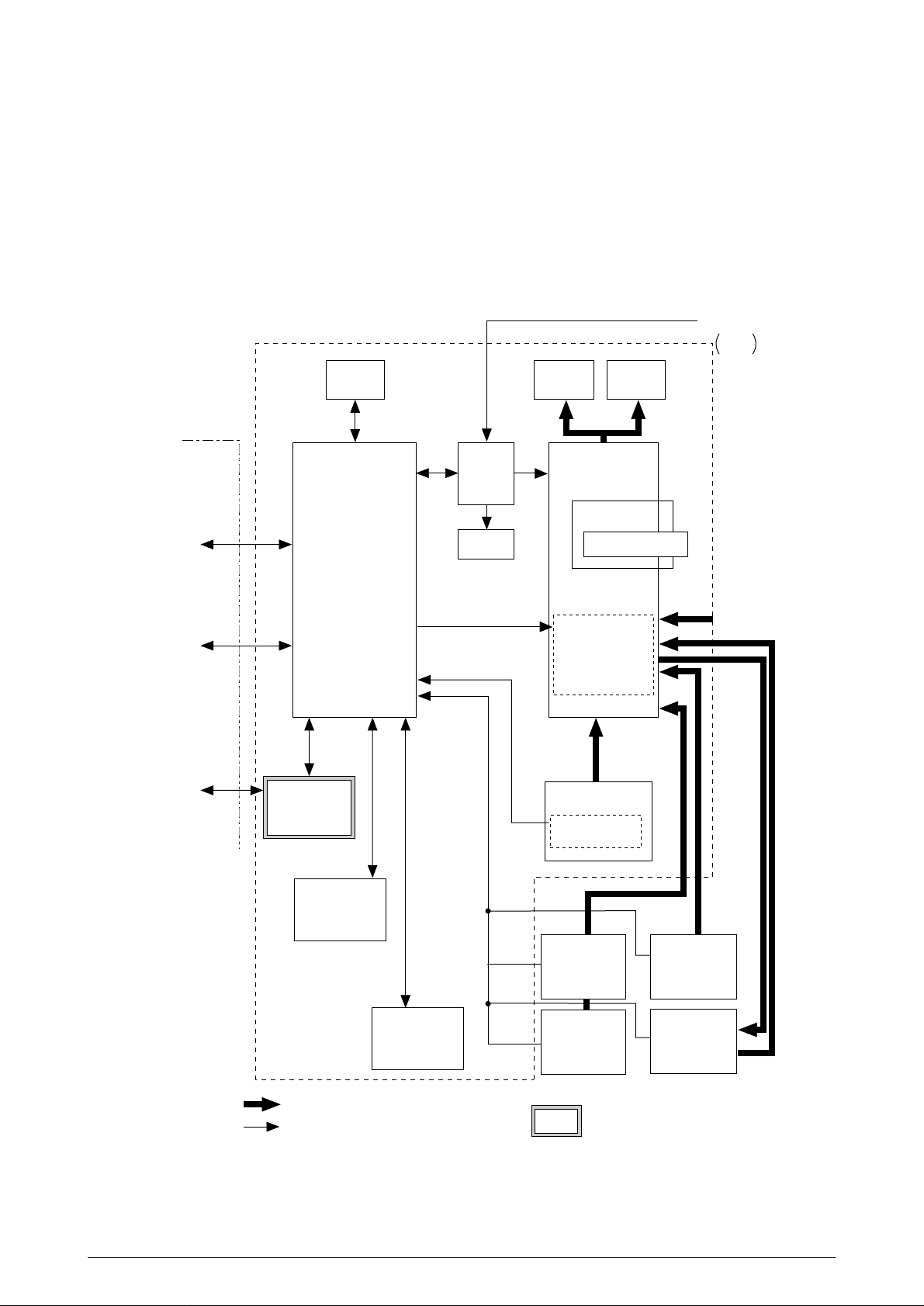
1.1 System Configuration
OKIPAGE24DX / OKIPAGE24dx consists of control and engine blocks as the standard configu-
ration (See Figure 1-1.)
In addition, the following options are also available.
PC etc.
Centronics
Parallel interface
(Bidirection)
RS-232C
Serial I/F
Printer
Operator
panel
Main control
Power
supply
unit
DC Fan
Face down
stacker
Printer
Mechanism
I/D unit
LED head
Motor-Main
Hopping motor
AC IN
120V
230V
Face up
stacker
*
*
Toner Cartridge
Front Feeder
LAN etc.
OKI HSP
interface board
(Option)
Extension D-RAM
SIMM
(Option)
: Paper feeding
: Singal flow
4MB/ 8MB
Flash ROM SIMM
(Option)
Figure 1-1
Paper tray
Paper size
detection switch
High Capacity
Second Paper
Feeder
(Option)
High Capacity
Third Paper
Feeder
(Option)
*: Consumables
: produced by third vender
Multi Feeder
(Option)
Duplex Unit
40930701TH DRAFT Vesion 7 /
Page 8
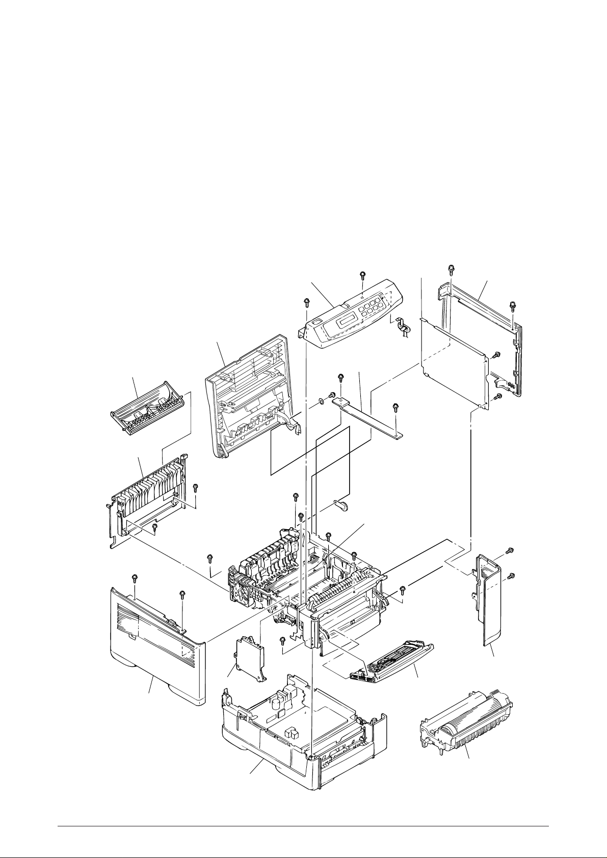
1.2 Printer Configuration
The printer unit consists of the following hardware components:
• Electro-photographic processor
• Paper feeder
• Controller
• Operator panel
• Power supply unit
• Duplex Unit
Figure 1-2 shows the printer unit configuration.
Stacker Assy
Frame-OP panel Assy
Plate-Shield
Cover-Side(I/F)
Face-up stacker Assy
Cover-Rear
Cover-Frame
Heat Assy
Cover-Side(R)
Contact Assy
Cover-Side(L) Assy
Base Unit
Manual Feed Assy
I/D Unit
Figure 1-2
40930701TH DRAFT Vesion 8 /
Page 9
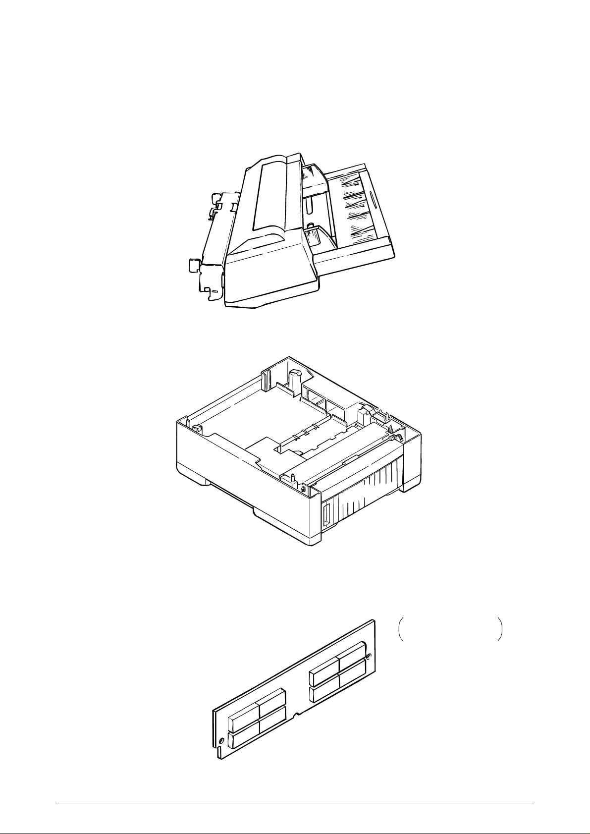
1.3 Optional Configuration
The options below are available for use with OKIPAGE24DX / OKIPAGE24dx. They are sold
separately from the printer unit.
(1) Multi Feeder
(2) Second/ Third Paper Feeder
(3) D-RAM SIMM module (72 pin SIMM, 16 MB/32 MB, EDO SIMM type)
See 7.2 (1) for where
to install.
40930701TH DRAFT Vesion 9 /
Page 10
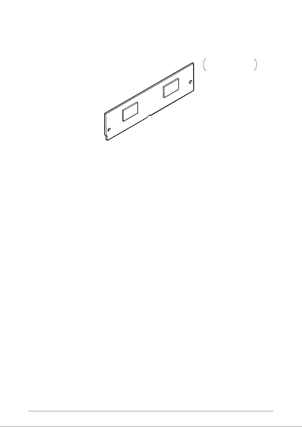
(4) Flash ROM module (72 pin SIMM, 4MB/8MB)
See 7.2 (1) for where
to install.
40930701TH DRAFT Vesion 10 /
Page 11

1.4 Specification
(1) Type Desk top
(2) External dimensions Height 13.0” (331 mm)
(excludes protruding Width 14.4” (366 mm)
Portion) Depth 18.2” (462 mm)
(3) Weight 21.3 kg (47 lbs)
(4) Development method Dry electrophotography
Exposure method LED stationary head
(5) Paper used <Type>
• Standard paper
– Xerox 4200 (20 lbs)
• Application paper (manual face-up feed)
– Label
– Envelope
– OHP paper (Transparency)
<Size>
• Standard sizes
– Letter
– Legal
– Executive
– Envelope (without Duplex printing)
–A4
– A5 (without Duplex printing)
– B5 (without Duplex printing)
– A6 (without Duplex printing)
• Applicable sizes
– Width: 3.4” to 8.5” (86 to 216 mm)
– Length: 5.5” to 14” (140 to 355.6 mm)
<Thickness>
– Automatic feed: 16 to 28 lbs (60 to 105 g/m2)
– Manual feed: Label, OHP paper (transparency)
Envelope, 16~36 lb
(6) Printing speed First print: 8 sec.
Continuous print: 20 sheets/min.
[at duplex print :10 sheets/min]
Warm-up time: 90 sec. [at room temperature 77˚F
(25˚C) and rated voltage (120 VAC)]
(7) Paper feed method Automatic feed or manual feed
(8) Paper delivery method Face down/face up
(9) Resolution 600 x 600 dots/inch (default)
600 x 1200 dots/inch
(10)Power input 120 VAC + 5.5%, –15% (ODA)
230 VAC + 10%
(11)Power consumption Peak: Approx. 820W
Typical Operation: Approx. 350W
Idle: Approx. 95W
Power save mode: Approx. 25W
40930701TH DRAFT Vesion 11 /
Page 12

(12) Temperature and humidity
In operation Power off mode During Storage Unit
Temperature 50 - 90 32 - 110 14 - 110 °F
(10 - 32) (0 - 43) (–10 - 43) (°C)
Humidity
Maximum wet
bulb temperature
Minimum difference
of wet and dry
bulb temperatures
20 - 80 10 - 90 10 - 90 %RH
77 80.4 °F
(25) (26.8) (°C)
35.6 35.6 °F
(2) (2) (°C)
Notes:
1. Storage conditions specified above apply to printers in packed condition.
2. Temperature and humidity must be in the range where no condensation occurs.
Temperature
(°C)
32
28
Operation range
10
20 80
Humidity (%)
(13) Noise During operation: 55 dBA or less
At standby: 45 dBA or less
Power save mode: 43 dBA or less
(14) Consumables Toner cartridge kit 6,000 pages(5% duty)*
Image drum cartridge 30,000 pages(at continuous Simplex printing)*
19,000 pages(3 page/job)(Simplex printing)*
* Simplex printing without Power Save.
40930701TH DRAFT Vesion 12 /
Page 13
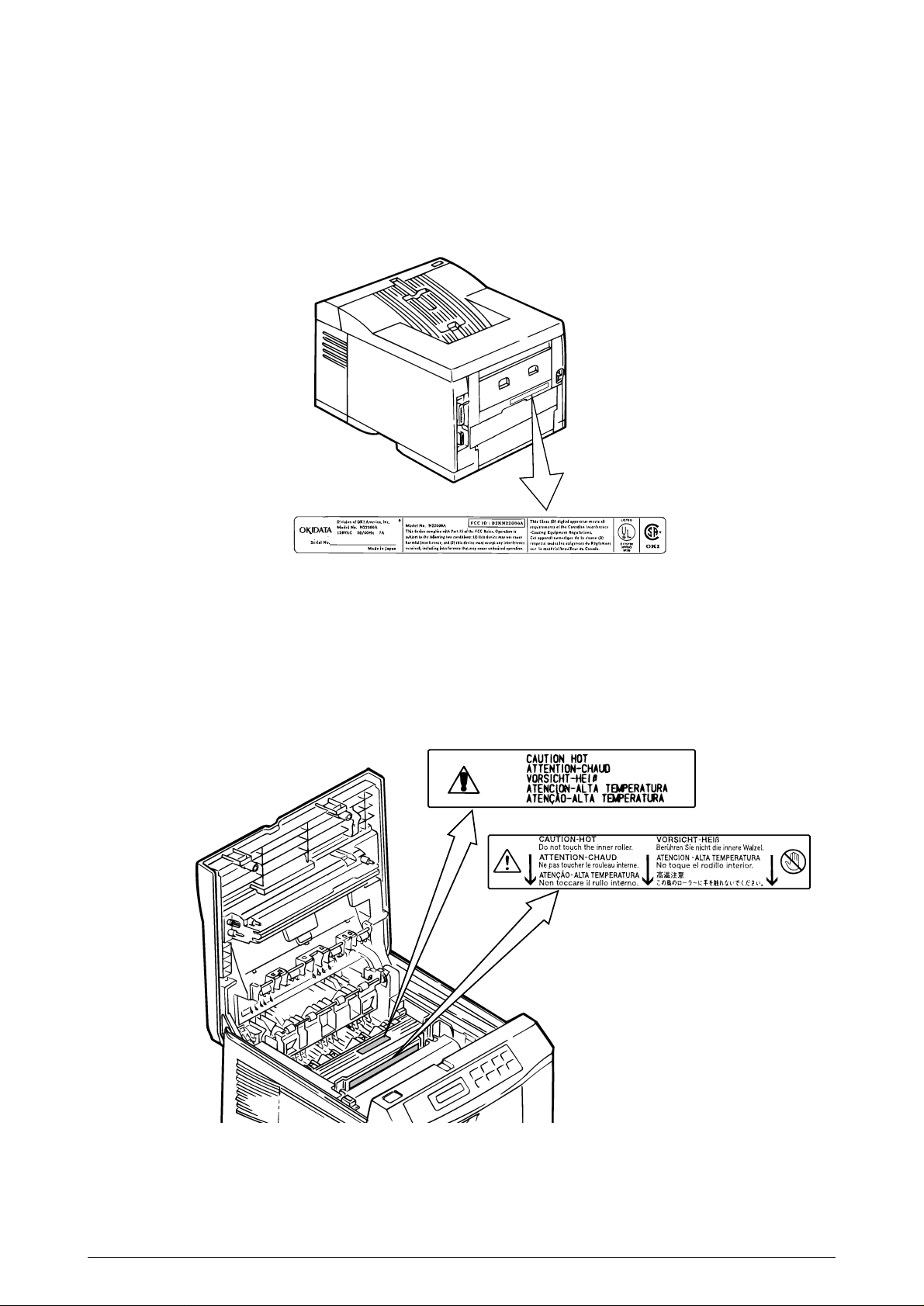
1.5 Safety Standards
ex. ODA 120V
1.5.1 Certification label
The safety certification label is affixed to the printer in the position below.
1.5.2 Warning label
The warning label is affixed to the portion which may cause an injury to human body.
Follow the instructions on warning labels during maintenance.
40930701TH DRAFT Vesion 13 /
Page 14

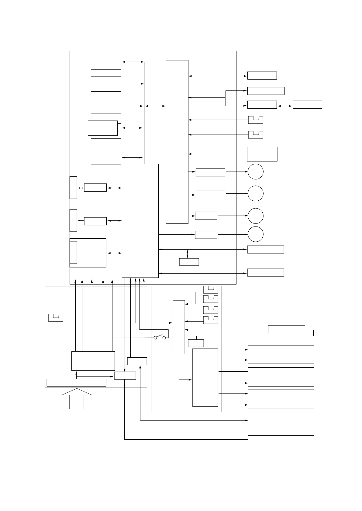
2. OPERATION DESCRIPTION
OKIPAGE24DX / OKIPAGE24dx consists of a main control board, a power supply unit (120V/
230V), a power supply unit (high voltage), an operator panel and an electro-photographic process
mechanism.
The control board receives data through a host I/F, decodes and edits the data, and stores the
edited data in a memory. After completing edition of one page of data, it references the font
memory and generates bit data on the same memory. At the same time, it transfers the bit image
data to an LED head in units of one dot line.
The electro-photographic process mechanism prints data on paper.
The operator panel is used for operations and status display.
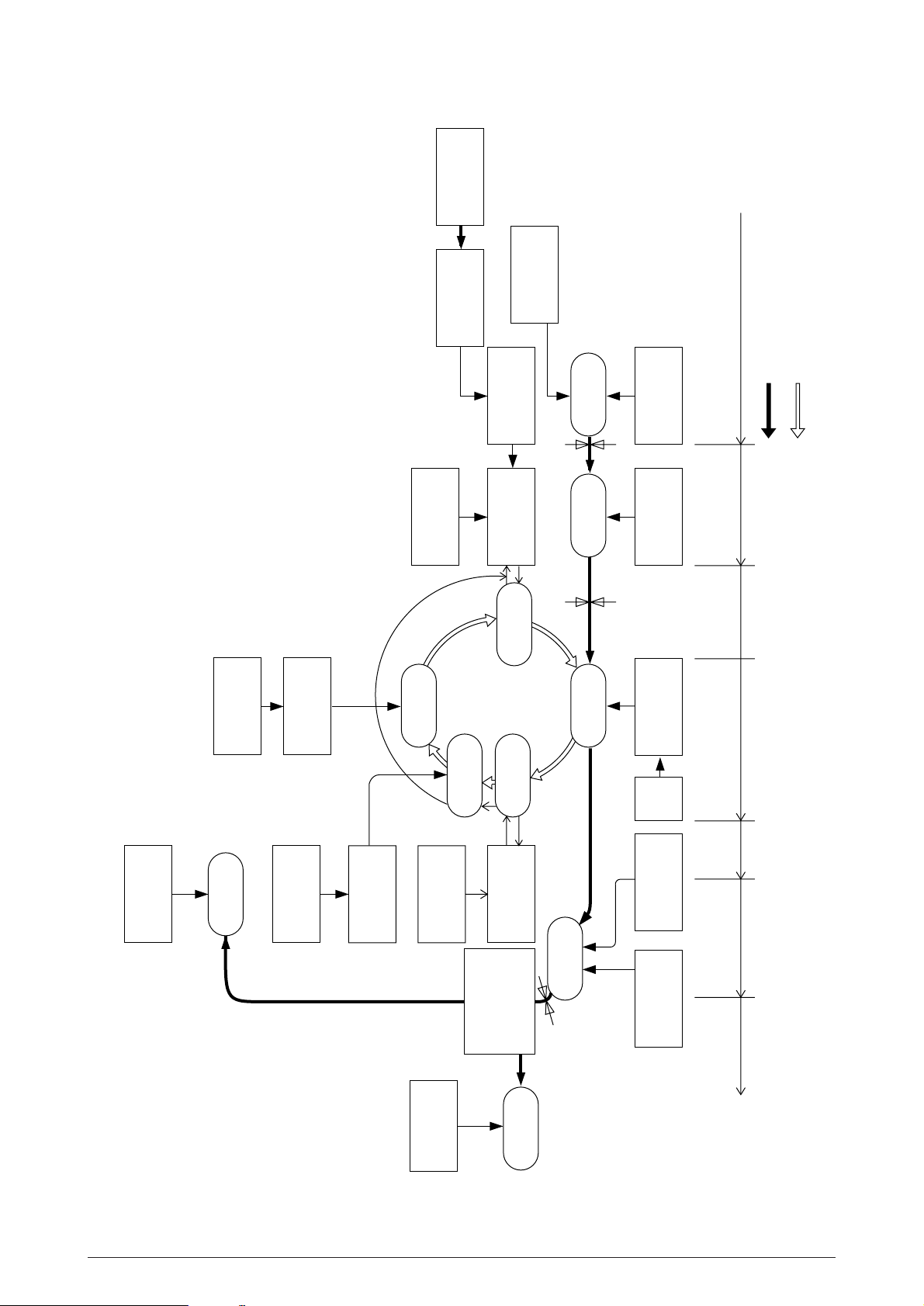
Fig. 2-1 shows an OKIPAGE24DX / OKIPAGE24dx block diagram.
40930701TH DRAFT Vesion 14 /
Page 15
FLASH ROM
Module
PS ROM
MAIN BOARD (BOARD-FFF)
DUPLEX unit
MULTI feeder
Centronics
I/F
RS232C
I/F
LAN etc.
(Option)
PCL ROM
Extension
DRAM
Module
DRAM
Driver
Receiver
Driver
Receiver
OKI
HSP I/F
Board
(Option)
3V 5V +8V -8V 38V
CPU
LSI
EEPROM
TRANSISTOR
TRANSISTOR
DRIVER
DRIVER
2nd tray
Paper end sensor
Paper near end sensor
BOARD PXC
Clutch for
CL
Regist Roller
Clutch for
CL
Hopping Roller
Hopping Motor
M
Main Motor
M
Operator panel
LED HEAD
3rd tray
Tray size
sensor board
POWER
SUPPLY
UNIT
(AC120V/230V)
Outlet sensor
FILTER CIRCUIT
AC120V/230V
LOW VOLTAGE
GENERATION
CIRCUIT
DRIVER
DRIVER
COVER
OPEN
SW
POWER
SUPPLY
UNIT
(high voltage)
LSI
0V
HIGH
VOLTAGE
CIRCUIT
Inlet sensor1
paper sensor
Inlet sensor2
Toner sensor
Sub-CH
CH
TR
DB
SB
CB
THERMISTOR
SUB CHARGE ROLLER
CHARGE ROLLER
TRANFER ROLLER
DEVELOPPING ROLLER
TONER SUPPLY ROLLER
CLEANING ROLLER
FAN
HEATOR
Figure 2-1 OKIPAGE24DX / OKIPAGE24dx block diagram
40930701TH DRAFT Vesion 15 /
Page 16

2.1 Main Control Board (BOARD-FFF)
The control board consists of an one chip CPU,a LSI, program/font ROM's, DRAM's, an
EEPROM, a host interface circuit, and a mechanism driving circuit.
(1) One-chip CPU
The one-chip CPU is a custom CPU (32-bit internal bus, 32-bit external bus, 120-MHz clock)
that incorporates an RISC CPU and its peripheral devices, and has the following functions.
Built-in device Function
Chip select controller Control of peripheral LSI, ROM, DRAM and I/O device
Bus controller
DRAM controller
DMA controller Transfer of data from Host I/F to RAM
Serial interface controller Control of RS232C serial interface
Parallel interface controller Control of Centronics parallel interface
Timer Generation of various control timing
Monitoring of paper running and paper size
Serial I/O port Control of serial interface between controller and operator panel, EEPROM
Control of a serial interface between controller and power supply board
I/O port Inputting of various sensor signals
Outputting of various control signals
Motor driver controller Control of Main Motor
Image processing circuit Executes the image data process for printing.
(2) Program/font ROM's
• PCL ROM
The program/font ROM's store the HP LJ5 emulation program and various types of font.
MASK ROM is used as the program/font ROM's.
• PS ROM
The program/font ROM's store the Adobe PostScript Level 2 program and its fonts.
40930701TH DRAFT Vesion 16 /
Page 17

(3) DRAM's
16-Megabyte DRAM (64 Mbit DRAM x 2) is mounted as resident memory to be used for storing
the program and providing various buffers. This DRAM is expandable up to 128 Mbytes by
adding expansion memory (SIMMs). This DRAM provides the areas shown in the following
table.
Memory area Use Memory capacity setting
MENU Expansion RAM
System area Fixed Fixed
Raster buffer Enable Expandable
Receive buffer Enable Expandable
Page buffer – Expandable
DLL/macro buffer – Expandable
Font cache buffer Enable Expandable
Working area used for the program
Stores converted bit image data
Stores temporarily the data received
from the host interface
Adds print information to the analyzed
receive data and stores the resulted
data.
Stores soft fonts and macro data.
Stores bit map fonts generated by the
font rasterizer based on scalable font
information
(4) EEPROM
The EEPROM has a 16-kbit capacity and stores the following data.
• Menu data
• Various counter data (page counter, drum counter, fuser counter, etc.)
• Adjustment parameters (LED head drive time, print start position, etc.)
(5) LSI (LZ9FF22)
Built in device Function
Serial I/O port Control of serial interface between controller and 2nd tray, 3rd tray, Multi purpose feeder
Control of serial interface between controller and Duplex unit
Motor driver controller Control of Hopping motor
I/O port Inputting of various sensor signals
Outputting of various control signals
(6) Host interface
This printer has the following interfaces to the host.
• Centronics bidirectional parallel interface
• RS232C interface
• OKI HSP interface (Option)
The single effective interface or the automatic interface select mode can be selected using
the menu. If the busy state of the printer continues for a long time period, the buffer nearfull control releases the busy status at constant intervals even if the host side is busy so not
to cause the interface time-out at the host side.
40930701TH DRAFT Vesion 17 /
Page 18

(a) Centronics bidirectional parallel interface
This is an interface conforming to IEEE-1284 and provides either of unidirectional and
bidirectional communications according to each of the following communication modes.
• Compatibility mode
Unidirectional communications from the host to the printer.
• Nibble mode
This mode transmits 4-bit wide data from the printer to the host. In this mode, each
1-byte data is transferred in the form of two nibbles using ERROR, BUSY, FAULT,
and SELECT signal leads. This mode can provide the bidirectional operation in
combination with the compatibility mode.
• ECP mode
This mode provides the asynchronous bidirectional interface and transmits and
receives 1-byte data using eight data signal leads under the semi-duplex control by
the host.
When the power is turned on, the compatibility mode is automatically selected. The
change to another mode from the compatibility mode is made through negotiation.
(When the BI DIRECTION is set to ENABLE in the menu, this change can be performed.)
(For the electrical/physical characteristics of this interface, see APPENDIX B)
(b) RS232C serial interface
The following protocol is supported for the serial interface conforming to EIA RS232C.
• READY/BUSY (DTR HI or DTR LO)
• X-ON/X-OFF
• RBST X-ON
(For the electrical/ physical characteristics of the interface, see APPENDIX B)
(c) OKI HSP interface (Option)
This interface (slot) is an OKI unique universal interface that provides the platform to
connect various of boards (including those supplied by third venders) such as the LAN
connection expansion board and SCSI expansion board.
Any expansion boards compatible with this interface can be mounted on the Control
board in the piggyback board from without modifying the program at the printer side. The
conceptual diagram of the OKI HSP interface is shown in Figure 2-2.
(For the electrical/physical characteristics of the OKI HSP interface, see the OKI HSP
interface technical manual.)
Printer
Network, etc.
Control board
LAN
expansion board
OKI HSP
interface
Figure 2-2
40930701TH DRAFT Vesion 18 /
Page 19
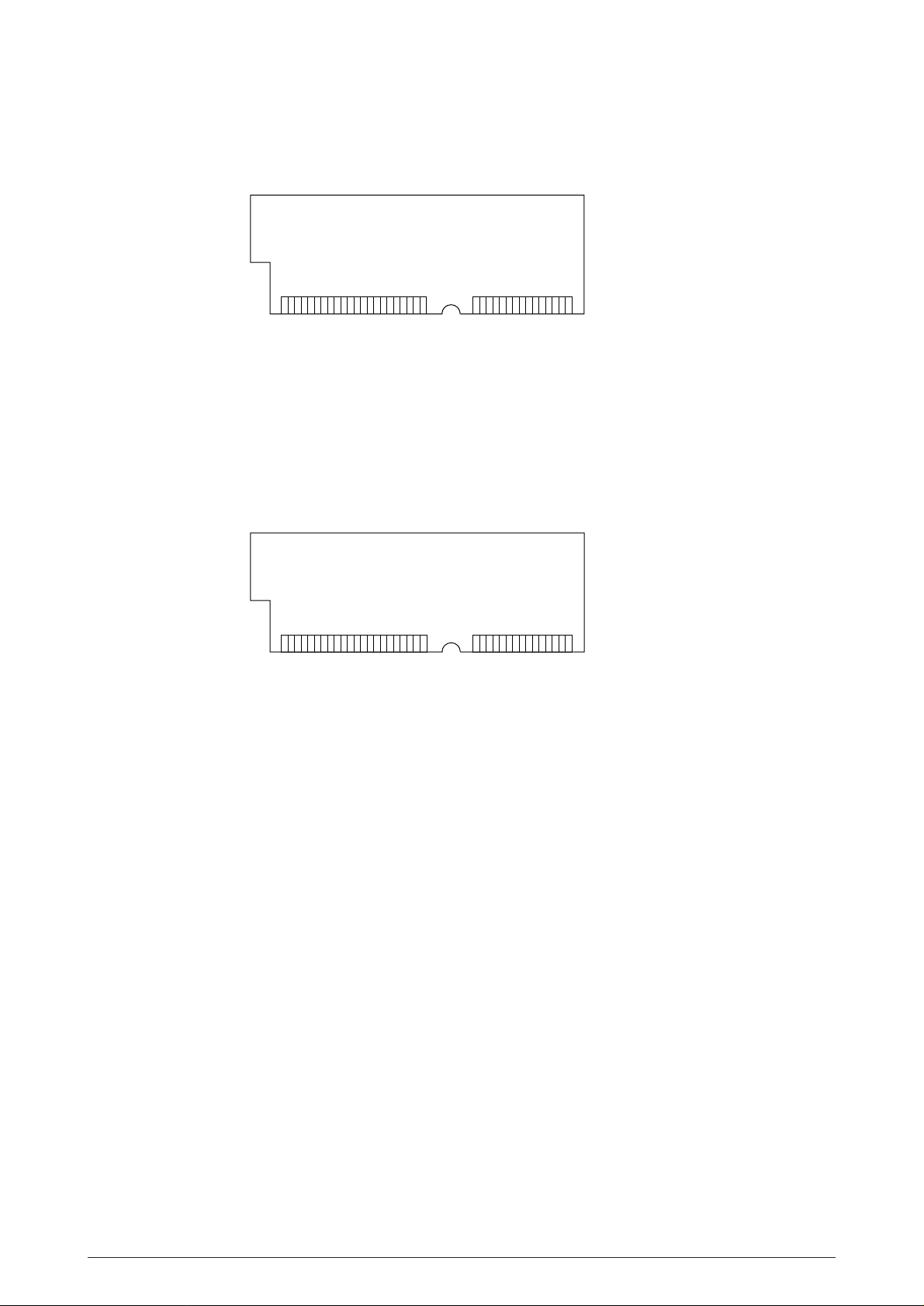
(7) RAM module
• Pin layout
1363772
• Basic specificaton
- Type: 72 pins Standerd SIMM (32 bits buss width)
- Access time: 60ns, 70ns, 80ns, 100ns
- Capacity: 16 or 32MB
- Parity: None
(8) Flash ROM module
• Pin layout
Board-FSL or Board-FSL-2
(4MB)
[Note : EDO SIMMtype]
(8MB)
1363772
• Basic specificaton
- Type: 72 pins SIIM (32 bits buss width)
- Access time: 90ns
- Capacity: 4 or 8MB
40930701TH DRAFT Vesion 19 /
Page 20

2.2 Power Supply Unit
The power supply unit consists of an AC filter circuit, a low voltage power supply circuit, a high
voltage power supply circuit, heater drive circuit, and photosensors.
(1) Low voltage power supply circuit
This circuit generates the following voltages.
Output voltage Use
+5 V Logic circuit supply voltage
+30 V Motor and fan drive voltage and source voltage for high-voltage supply
+8 V Reset circuit, RS232C Line voltage
–8 V RS232C Line voltage
+3.8V LED HEAD supply voltage
(2) High voltage power supply circuit
This circuit generates the following voltages necessary for electro-photographic processing
from +30 V according to the control sequence from the control board. When cover open state
is detected, +30 V supply is automatically interrupted to stop the supply of all the high-voltage
outputs.
Output Voltage Use Remarks
Sub-CH -15 µA Voltage applied to Sub charging roller
CH -1.30 KV Voltage applied to charging roller
DB -220 V/+300 V Voltage applied to developing roller
SB -450 V Voltage applied to toner supply roller
TR +4 KV/-1.3 kV Voltage applied to transfer roller Variable + Only
CB +450 V/-1350V Voltage applied to clearimng roller
(3) Photosensor
The photosensor mounted on this power supply unit supervises the paper running state
during printing.
40930701TH DRAFT Vesion 20 /
Page 21

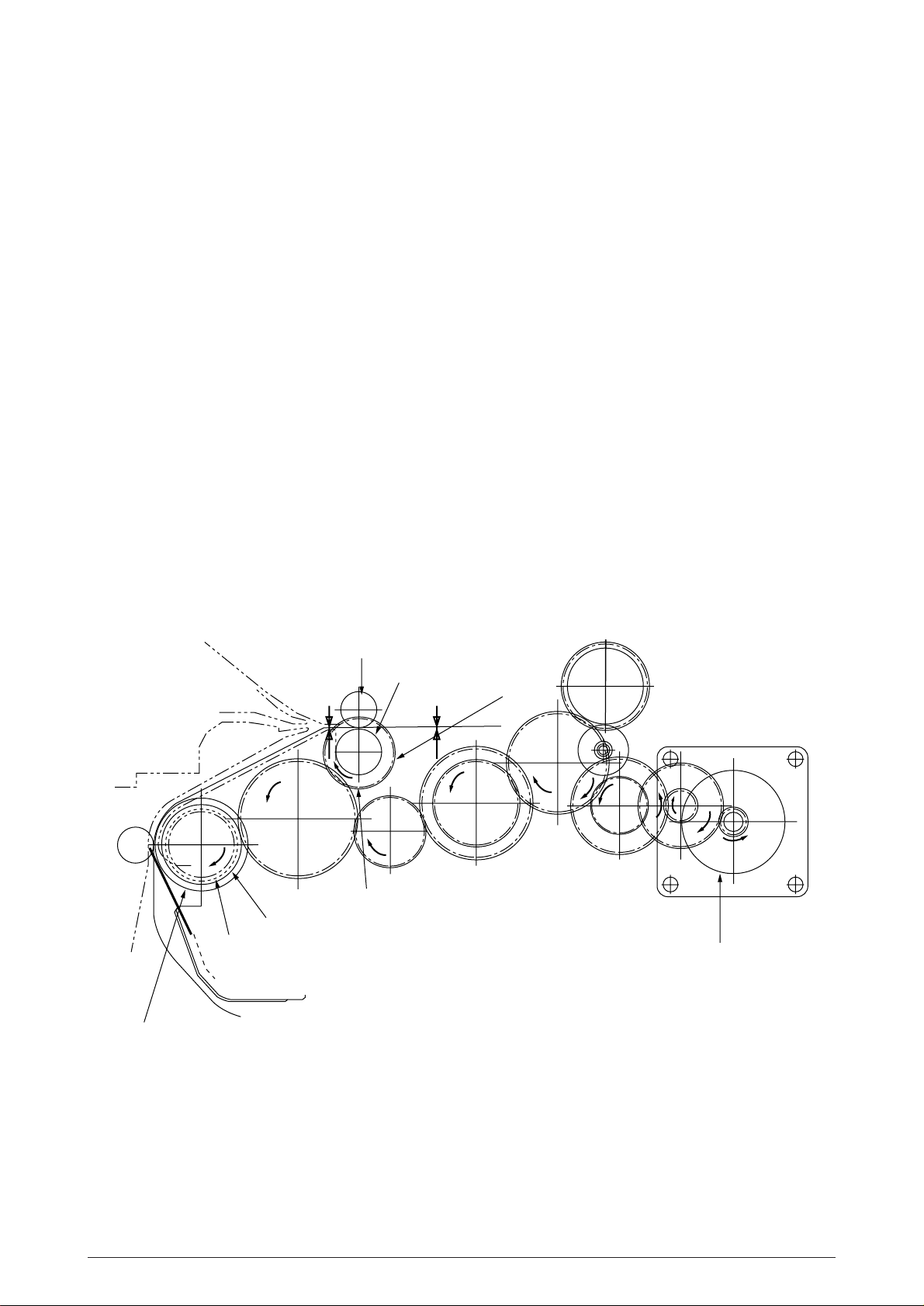
Figure 2-3 shows the sensor layout diagram.
Paper running direction
Roller-Heat
Roller-transfer
Roller-exit
Roller-feeder (c)
Outlet sensor
Sensor
Inlet sensor 1
Inlet sensor 2
Toner sensor
Inlet sensor 1
Inlet
sensor 2
Paper sensor
Roller-regist
Feed roller
Figure 2-3
Function
Detects the leading part of the paper and gives the supervision
timing for switching from hopping operation to feeding operation.
Supervises the paper running state and the paper size according to the paper reach time and running time.
Detects the form width.
ON: Paper exists.
OFF: No paper exists.
ON: A4 or larger
OFF: Smaller than A4
Sensing state
Paper sensor
Outlet sensor
Toner low sensor
40930701TH DRAFT Vesion 21 /
Detects the leading part of the paper.
Supervises the paper running state.
Supervises the paper feed and size according to the time of
arrival to the sensor and the time of passage of paper.
Detects the lack of toner.
ON: Paper exists.
OFF: No paper exists.
ON: Paper exists.
OFF: No paper exists.
ON long: Toner low exists
OFF short: No Toner low exists
Page 22
2.3 Electro-photographic Process
2.3.1 Electro-photographic process mechanism
This mechanism prints image data from the control board on the paper by electro-photographic
process.
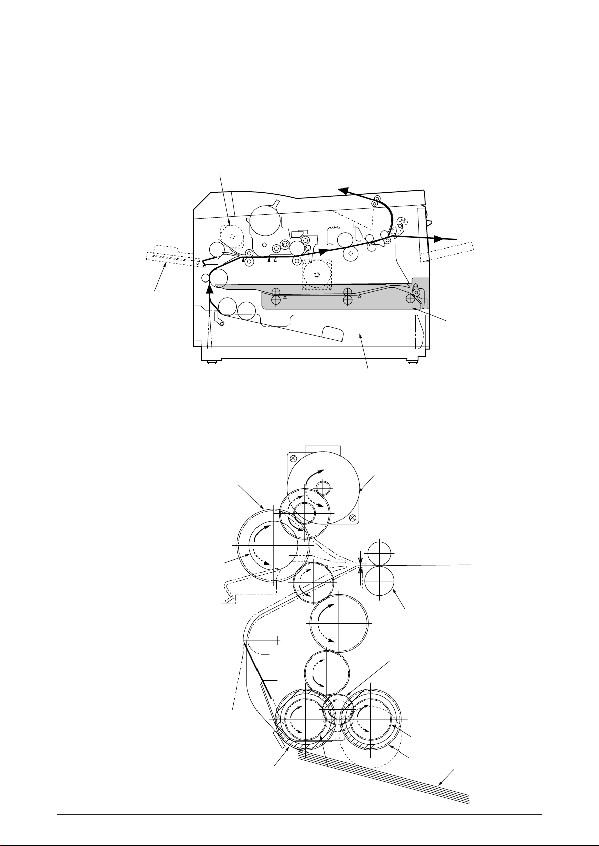
The Figure 2-4 shows the layout of the electro-photographic process mechanism.
Front Hopping Roller
Front Feeder
Roller Assy-Feed
Image Drum Unit
Hopping Motor
1st Hopping Roller
Sub Roller
LED HEAD
Motor-Main
Heat Assy
Face Up stacker
Duplex Unit
Figure 2-4
40930701TH DRAFT Vesion 22 /
Page 23

(1) Image drum unit
The image drum unit consists of a sensitive drum, a charger, and a developer. The unit forms
a toner image on the sensitive drum, using a electrostatic latent image formed by the LED
head.
(2) Hopping motor
This motor is a pulse motor of 48 steps/rotation that is two-phase excited by the signal from
the control board. It drives the hopping roller of the first tray and the front feed roller via two
one-way clutches according to the direction of rotation.
(3) Motor-Main
This motor is a pulse motor of 72 steps/rotation that is two-phase excited by the signal from
the control board and is the main motor of this mechanism.
(4) Clutch (for Regist)
Swithes the transfer of power to Roller Regist if necessary depending on the power from
Motor-Main and instructions from the control PCB.
(5) Clutch (for Feed Roller)
Swithes the transfer of power to Feed Roller if necessary depending on the power from
Motor-Main and instructions from the control PCB.
(6) LED head
Image data for each dot line from the control board is received by the shift register and latch
register. The 4992 LEDs are driven to radiate the image data to the image drum.
(7) Fuser
The fuser consists of a heater, a heat roller, a thermistor and a thermostat.
An AC voltage from the power supply board is applied to the heater under the control of the
HEATON signal from the control board. This AC voltage heats the heater. The control board
supervises the heat roller temperature via the thermistor, and regulates the heater roller at
a predetermined temperature (185 °C : Normal paper, MEDIA TYPE = MEDIUM) by
connecting or disconnecting the AC voltage supply to the heater.
If the heater roller temperature rises abnormally, the thermostat of the heater voltage supply
circuit is activated to cut the AC voltage supply forcibly.
(8) Duplex Unit
Duplex Unit is a unit, which is installed on the printer unit for controlling both-sided printing
from the printer unit, intended for automatically reversing paper of which one side have been
already printed and re-feeding them to the unit for printing other side.
40930701TH DRAFT Vesion 23 /
Page 24

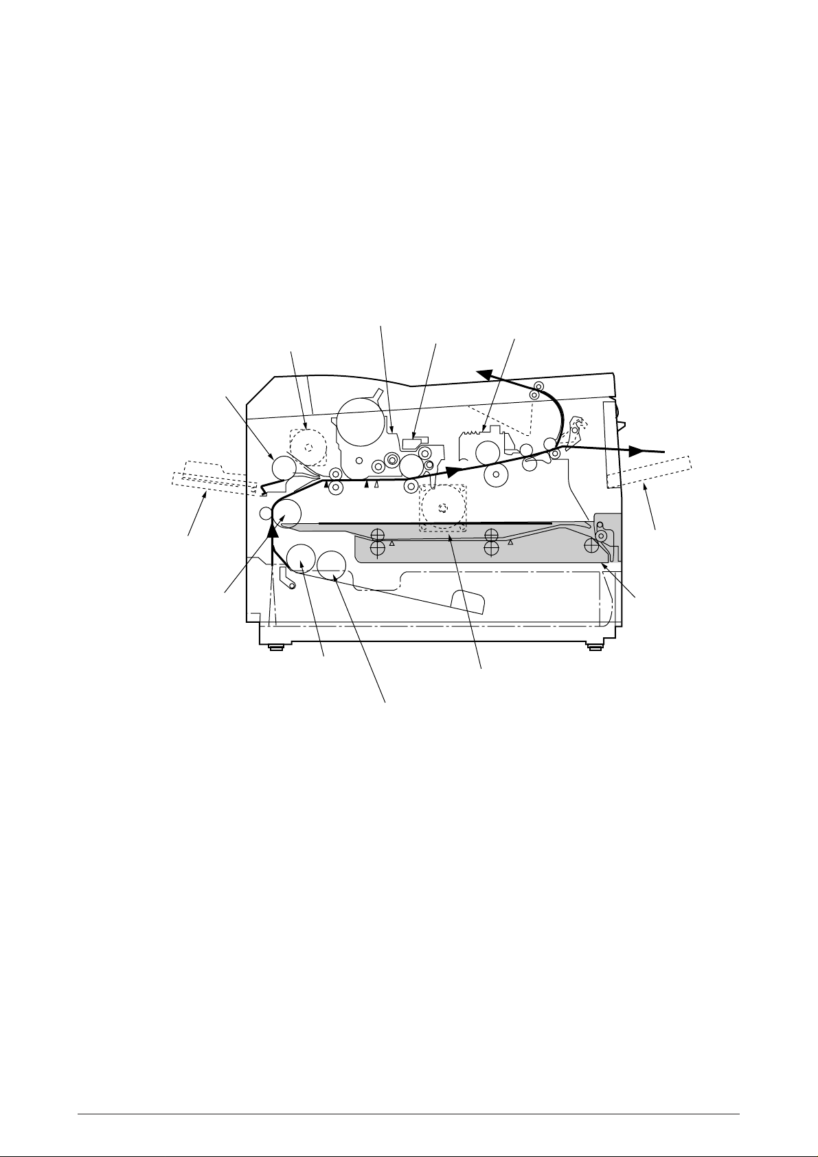
2.3.2 Electro-photographic process
The electro-photographic processing is outlined below. Figure 2-5 shows the electro-photo-
graphic printing process.
1 Charging
The surface of the image drum is uniformly charged with negative charges by applying a
negative voltage to the charge roller.
2 Exposure
Light emitted from the LED head irradiates the negatively charged surface of the image drum.
The surface potential of the irradiated part of the image drum surface is lowered, so that an
electrostatic latent image associated with the print image is formed.
3 Developing and toner recovery
When the negatively charged toner is brought into contact with the image drum, it is attracted
to the electrostatic latent image by static electricity, making the image visible.
At the same time, the residual toner on the image drum is attracted to the developing roller
by static electricity.
4 Transfer
When paper is placed over the image drum surface and a positive charge, opposite in polarity
to the toner, is applied to the reverse side of the paper from the transfer roller, the toner is
attracted by the positive charge and is transferred to the paper. As a result, the toner image
formed on the image drum is transferred to the paper.
5 Temporary cleaning
Residual toner that remains on the image drum without being transferred is made uniform
by the cleaning roller and is temporarily attracted to the cleaning roller by static electricity.
6 Fusing
The toner image transferred to the paper is fused under heat and pressure.
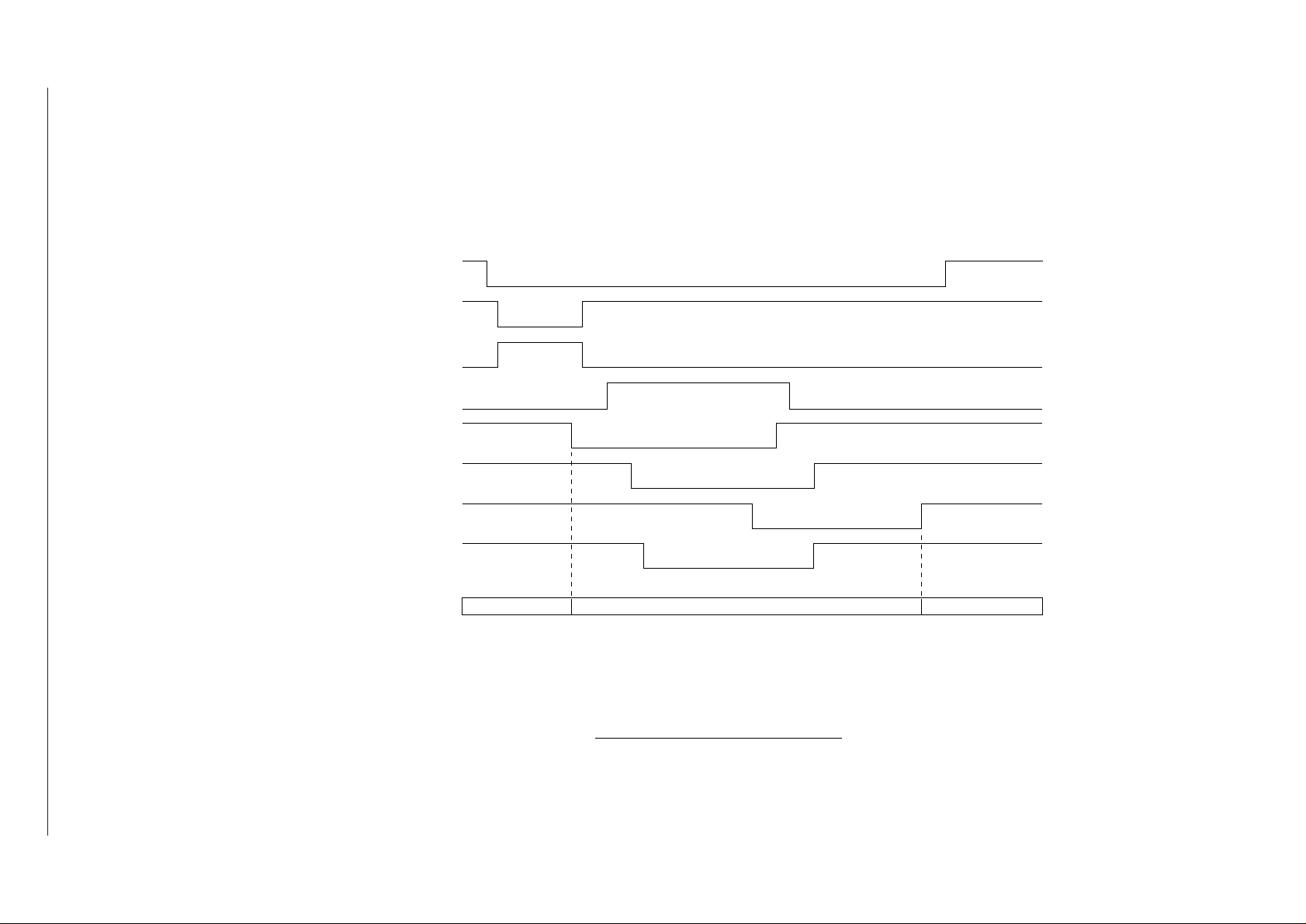
Figure 2-6 shows an electro-photographc process timing chart.
40930701TH DRAFT Vesion 24 /
Page 25
Toner
cartridge
Toner
supply roller
Front
feeder
Path of paper feeding
Direction of rotation of
the image drum
Image data
LED head
Power
supply
(Bias voltage)
Exposure
Charging
blade
Doctor
Inlet sensor
roller
Developing
Paper sensor
Developing
Cleaning
Paper
supply
Paper
registration
Transfer
roller
Hopping
roller
Registration
Image
production
roller
Transfer
Power
supply
developing Paper feed Paper hopping
eject
roller
Paper
eject
Paper
Power
(Face down)
supply
roller
Charger
Power
eject
Paper
supply
roller
Cleaning
path
Paper
selector
roller
eject
Paper
Fusing
Outlet sensor
(Face up)
Fusing pressure
Heater roller
Paper eject Fusing Cleaning Transfer
Figure 2-5
40930701TH DRAFT Vesion 25 /
Page 26
40930701TH DRAFT Vesion 26 /
DMON-N (DRUM MOTOR)
HMON-N (HOPPING MOTOR)
PWM1-P (CLUCH for hopping)
PWM2-P (CLUCH for REGISTRATION)
Figure 2-6
PSIN1-N (INLETSENSOR1)
WRSENSE-N (PAPER SENSOR)
PSOUT-N (OUTLET SENSOR)
STB-N (LED HEAD)
OFF
ON
OFF
ON
ON
OFF
ON
OFF
OFF
ON
OFF
ON
OFF
ON
OFF
ON
PAPER TRAYPAPER PRINTER
STACKER
SIMPLEX PRINTING TIMING CHART
Page 27
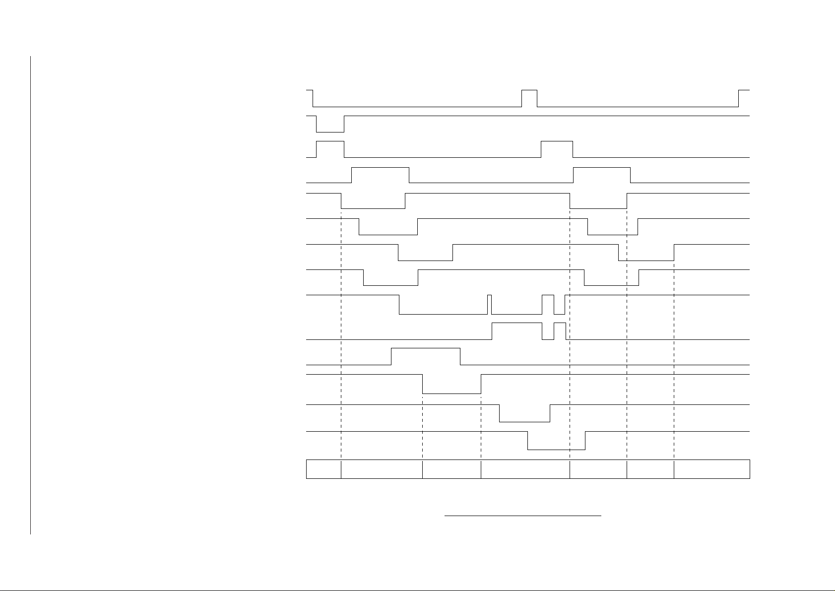
40930701TH DRAFT Vesion 27 /
DMON-N (DRUM MOTOR)
HMON-N (HOPPING MOTOR)
PWM1-P CLUCH for hopping)
PWM2-P (CLUCH for REGISTRATION)
PSIN1-N (INLETSENSOR1)
WRSENSE-N (PAPER SENSOR)
PSOUT-N (OUTLET SENSOR)
Figure 2-7
STB-N (LED HEAD)
DUPMON-N (MAIN MOTOR in DUPLEX
UNIT)
CLON-P (CLUCH in DUPLEX UNIT)
SLON-P (SOLENOID in DUPLEX UNIT)
DUPINSNS-N (INLET SENSOR in
DUPLEX UNIT)
DUPRSNS-N (REAR SENSOR inDUPLEX
UNIT)
DUPFSNS-N (FRONT SENSOR in
DUPLEX UNIT)
OFF
ON
OFF
ON
ON
OFF
ON
OFF
OFF
ON
OFF
ON
OFF
ON
OFF
ON
OFF
ON
ON
OFF
ON
OFF
OFF
ON
OFF
ON
OFF
ON
PAPER PRINTER PRINTER STACKERDUPLEX UNIT
PAPER
TRAY
PRINTER/
DUPLEX UNIT
DUPLEX UNIT/
PRINTER
DUPLEX PRINTING TIMING CHART
Page 28
2.4.3 Process operation descriptions
(1) Hopping
Hoppings from the first tray and the front feeder are effected by a single hopping motor in the
mechanism shown below.
Hopping Motor
Front Feeder
Duplex Unit
1st Tray
Turning the Hopping motor in direction a (CW) drives the 1st Hopping Roller. Turning the
Hopping motor in direction b (CCW) drives the Front Hopping Roller. Gear C and Hopping
roller bult in one-way bearing, so that turning each of these gears in reverse direction will not
be transmitted to the corresponding roller.
Gear C
(One-way Clutch build-in )
Front Hopping Roller
(One-way clutch build-in)
a
(CW)
(CCW)
b
Inlet Sensor
Hopping Motor
Roller-Regist
Planet Gear
Gear B
1st Hopping Roller
(One-way clutch build-in)
Sub Roller
Gear A
Paper
40930701TH DRAFT Vesion 28 /
Page 29
(a) Hopping from the 1st Tray
1 Hopping
Rotating the Hopping Motor in direction a (CW) drives the 1st Hopping Roller and
the Sub Roller then pick up a sheet of paper in the 1st tray. The Main Motor is always
driven in direction c (CCW) on printing. After the paper fed approx. 30mm from the
tray, the Clutch (Feed) drives the Align Roller to advance the paper until the Inlet
Sensor turns on.
2 Aligning
After turning on the Inlet Sensor, the paper fed by a predetermined length and
choked up to the wedge space formed by the Regist Roller and the Pressure Roller
so that to align the skew of paper.
3 During the paper fed from the 1st tray, the build in clutch of Gear C is idled and not
to drive the Front Hopping Roller.
4 Feeding
After aligned the paper, the Hopping Motor turned off and stop hopping. Also the
Clutch (Feed) turned off and the Align Roller idled freely. Then Clutch (Regist)
turned on and the Regist Roller start to feed the paper. After the paper fed, the 1st
Hopping Roller is freely idled by releasing build in one way clutch, also the Sub
Roller is freely idled by escaping the Planet Gear.
5 Start printing. after the paper turns off the Write Sensor.
Align Roller
Clutch (Feed)
Gear D
Pressure Roller
Inlet Sensor
Gear E
Regist Roller
Write Sensor
Clutch (Regist)
c
Main Motor
40930701TH DRAFT Vesion 29 /
Page 30

(b) Hopping from the Front Feeder
1 Hopping
The Front Feeder Plate is normally locked at the lower position by the Release
Lever and turn the Micro SW on. Top of the FF Cam which attached on end of the
Front Hopping Shaft is normally located Upper position (0 to 30 degree : home
position). Rotating the Hopping Motor in direction b (CCW) drives the Front Hopping
Shaft and then attached the FF Cam and the Front Hopping Roller are driven.
During the FF Cam rotated approx. 60 degree, the Release Lever was pushed and
the Front Feeder Plate lifts up, then the Front Hopping Roller picks up a sheet of
paper. At the FF Cam rotated approx. 180 degree, the Front Feeder Plate is pushed
down and locked by the Release Lever again. At the FF Cam rotated approx. 275
degree the paper fed until the Inlet Sensor turns off.
2 Aligning
After turning on the Inlet Sensor, the paper fed by a predetermined length and
choked up to the wedge space formed by the Regist Roller and the Pressure Roller
so that to align the skew of paper.
3 During the paper fed from the Front Feeder Plate, the one way clutch of 1st Hopping
Roller is idled and not to drive the 1st Hopping Roller and the Sub Roller.
4 Feeding
After aligned the paper, the Hopping Motor turned off and stop hopping. Then Clutch
(Regist) turned on and the Regist Roller start to feed the paper. After the paper fed,
the Front Hopping Roller drives the Front Hopping Shaft and attached the FF Cam
with small idle torque of build in one way clutch and when comes into the Release
Lever, the one way clutch is slipped and the FF Cam is stopped at the upper position
(home position). The Front Hopping Roller continuously idled up to the paper away.
5 Start printing. after the paper turns off the Write Sensor.
40930701TH DRAFT Vesion 30 /
Page 31

Hopping Roller
(Front Feeder)
Gear C
(one way clutch build in)
Hopping Motor
b (CCW)
Pressure Roller
Front Feeder Plate
Paper
Gear A
Hopping Roller
Inlet Sensor
d
1st Hopping Gear
(One way Gear build in)
Regist Roller
Paper
Sub Roller
(home position)
0~30
°
60
°
180
°
Release Lever
Front Hopping Shaft
FF Cam
Micro SW
Front Feeder Plate
40930701TH DRAFT Vesion 31 /
Page 32

Align Roller
Gear D
Inlet Sensor
Clutch (Feed)
Pressure Roller
Regist Roller
Write Sensor
Gear E
Clutch (Regist)
c
Main Motor
(2) Feeding
After the end of hopping, the pulse motor dedicated for driving the registration roller rotates
to drive the registration roller. The driven registration roller advances the paper until it comes
out of the registration roller.
When leading edge of the paper causes the paper sensor to turn on, the printing is started
synchronously.
Although Gear D is always rotating due to an all-time rotation of the main motor in direction
c, the regist roller would not rotate because the clutch (regist) is turned off.
After the completion of hopping, turn on the clutch (regist) to drive the regist roller. The regist
roller would drive a paper until the paper has passed.
40930701TH DRAFT Vesion 32 /
Page 33

(3) Charging
Charging is effected by applying a DC minus voltage to the charge roller that is in contact with
the image drum surface.
Power
supply
Image drum
Charge roller
(4) Exposure
Power
supply
Light emitted from the LED head irradiates the image drum surface with negative charges.
The surface potential of the irradiated part of the image drum drops, thereby forming an
electrostatic latent image associated with the image signal.
LED head
Charge roller
Image drum
LED head
Paper
Image drum
40930701TH DRAFT Vesion 33 /
Page 34

(5) Developing
Toner is attracted to the electrostatic latent image on the image drum surface to convert it
into a visible toner image. Developing takes place at the contact between the image drum
and the developing roller.
1 As the toner supply roller rotates while rubbing on the developing roller, a friction charge
is generated between the developing roller and the toner, allowing the toner to be
attracted to the developing roller. (The developing roller surface is charged positive and
the toner, negative.)
Doctor blade
Charge roller
Toner supply roller
Image drum
Developing roller
2 The toner attracted to the developing roller is scraped off by the doctor blade, forming
a thin coat of toner on the developing roller surface.
3 Toner is attracted to the exposed part (low-potential part) of the image drum at the
contact between the image drum and the developing roller, making the electrostatic
latent image visible.
40930701TH DRAFT Vesion 34 /
Page 35

(6) Transfer
The transfer roller is composed of conductive sponge material and is designed to make the
image drum surface and the paper closely into contact.
Paper is placed over the image drum surface, and a positive charge, opposite in polarity to
the toner, is applied to the paper from its reverse side.
The application of a high positive voltage from the power supply to the transfer roller causes
the positive charge induced to the transfer roller surface to be transferred to the paper at the
contact between the transfer roller and the paper. As a results, toner charged negative that
is attracted to the image drum surface is transferred to the upper side of the paper by the
positive charge on the lower side of the paper.
Image drum
Transfer roller
Paper
Power
supply
40930701TH DRAFT Vesion 35 /
Page 36

(7) Fusing
After the end of the transfer, the unfused toner image is fused on the paper under heat and
pressure as it passes between the heater roller and the back-up roller. The heater roller with
a Teflon coating incorporates a 750W heater (Halogen lamp), which heats the heat roller.
A thermistor which is in contact with the heater roller regulates the heater roller at a
predetermined temperature (about 180 ~ 200°C). A safety thermostat cuts off voltage supply
to the heater by opening the thermostat in the event of abnormal temperature rises.
The back-up roller is held under a pressure of 5 kg from the pressure spring at each side.
Heater
Paper
Separation Claw
Thermistor
Heater Roller
Roller-BK
Pressure Spring
40930701TH DRAFT Vesion 36 /
Page 37

(8) Cleaning
After the end of the transfer, residual toner on the image drum is attracted to the cleaning
roller temporarily by static electricity to clean the image drum surface.
Image Drum
Cleaning Roller
Power
Supply
Transfer Roller
(9) Cleaning of rollers
The charge roller, transfer roller and cleaning roller are cleaned in the following cases:
• In warming up at power-on time
• In warming up after the cover is opened and closed
• When the number of accumulated sheets is 10 or more and the printout operation ends
Changes in bias voltage applied to each roller move adhesive toner from the roller to the
image drum and return it to the developer.
40930701TH DRAFT Vesion 37 /
Page 38

(10) Duplex unit
When the Duplex Unit receives an instruction for both-sided printing from the unit, the
separator will be opened by the action of a solenoid within Duplex and the route will be shifted
to the one into the Duplex after one-sided printing of papers, which are fed from the tray, are
completed.
At this time, as the roller (1) rotates in the direction of arrow A, a sheet is retracted in the rear
of the cassette. And then, a given time later after the edge of the sheet passes through the
IN SNS (DUP), the roller will reverse and the roller (1) rotates in the derection of arrow B and
sending out the paper into the Duplex. After that, it passes though the roller (2) and (3), and
is fed again into the unit, given another-sided printing and ejected.
Separator
IN SNS
(DUP)
Roller (3) Front
Sensor
Rear
Sensor
Roller (1)Roller (2)
<In retracting paper> <In sending out paper>
A
B
40930701TH DRAFT Vesion 38 /
Page 39

2.3.4 Revision of LED Head Illumination
An LED correcting head, which is capable of correcting the illumination of the LED for each dot,
is being used in this printer. LED illumination correction function of 16 steps is carried out by using
an EEPROM which is installed in the LSI that maintains the LED illumination correction values,
and an LED correction drivers together as a pair.
The LED correcting head consists of the correction control LSI , LED drivers , and an LED array.
The block diagram of the LED correcting head is shown below.
(1) Both sides wire-bonding head
Correction Control
LSI
EEPROM
STRB4-N
STRB3-N
DATA 3
DATA 2
LED Driver LED Driver
From
CPU
LOAD
CLOCK
STRB2-N
STRB1-N
DATA 1
DATA 0
LED LED LED LED LED LED LED
LED Driver LED Driver
LED Array
In OKIPAGE 20/ OKIPAGE 20n, the correction control of LED head is excuted direction by CPU.
The procedure is as follows
(i) LED head is set to the correction control read mode and all correction data stored in
EEPROM within the correction control LSI are read by CPU, and stored temporarily in
the memory.
(ii) Next, LED head is set to the correction control direct mode and the correction data stored
temporarily in the memory is transferred directly to the LED driver.
40930701TH DRAFT Vesion 39 /
Page 40

(i) Read of correction data
CLOCK
LOAD
DATA 3~0
STRB1-N
STRB2-N
STRB3-N
STRB4-N
Mode setting
RD Mode enabled
RD Mode set
RD
250ns min
High-Z
High-Z
data1 data3
correction data1
correction data2 correction data 4992
data2 data4
1000
dummy cycle
8 clocks
RD cycle
8 clocks
RD cycle
8 clocks
Head data read Correction data read
Total 19992 clocks
RD cycle
8 clocks
RD cycle
8 clocks
correction data 4991
40930701TH DRAFT Vesion 40 /
Page 41

01100
CLOCK
LOAD
DATA 3~0
STRB4~1
Mode setting
Total 2496 clocks
Correction data 1
Correction data 4991
Correction data 4992
Correction data 2
Correction data 4
Correction data 3
DIRECT Mode enabled
DIRECT Mode set
DIRECT
250ns min
(ii) Transfer of correction data to head driver correction data
40930701TH DRAFT Vesion 41 /
Page 42

(2) One side wire-bonding head
DATA 3
DATA 2
DATA 1
DATA 0
From
CPU
CLOCK
LOAD
STRB4-N
STRB3-N
STRB2-N
STRB1-N
Correction Control
LSI
EEPROM
LED Array
LED LED LED LED LED LED LED
LED Driver LED Driver
(i) LED head is set to the correction control read mode and all correction data stored in
EEPROM within the correction control LSI are read by CPU, and stored temporarily in
the memory.
(ii) Next, LED head is set to the correction control direct mode and the correction data stored
temporarily in the memory is transferred directly to the LED driver.
40930701TH DRAFT Vesion 42 /
Page 43

(i) Read of correction data
CLOCK
LOAD
DATA 3~0
STRB1-N
STRB2-N
STRB3-N
STRB4-N
Mode setting
RD Mode enabled
RD Mode set
RD
250ns min
High-Z
High-Z
data1 data3
correction data1
correction data2 correction data 5200
data2 data4
1000
dummy cycle
8 clocks
RD cycle
8 clocks
RD cycle
8 clocks
Head data read Correction data read
Total 20824 clocks
RD cycle
8 clocks
RD cycle
8 clocks
correction data 5199
40930701TH DRAFT Vesion 43 /
Page 44

01100
CLOCK
LOAD
DATA 3~0
STRB4~1
STRB1-N
STRB2-N
STRB3-N
STRB4-N
Mode setting
Total 5200 clocks
Correction data1 Correction data1300
Correction data1301
Correction data2
DIRECT Tp
Ditail figure A-D
A part of A A part of B A part of C A part of D
Tp Tp Tp
Tp > 2µs
Tp Tp Tp Tp
Tp
Correction data2600
Correction data2601
Correction data3900
Correction data3901
Correction data5200
more than 1µS
(ii) Transfer of correction data to head driver correction data
40930701TH DRAFT Vesion 44 /
Page 45

The LED driver corrects the LED illumination by controlling the LED current. The LED illumination
can be set in 16 steps, with 7 steps in the direction of illumination increase in relation to the
standard value, and 8 steps in the direction of decrease. For this reason, the LED correction data
is a 4-bit data for each dot.
The relationship between the LED correction data and LED current correction steps with the LED
driver used in an LED head is shown below.
LED Correction Data
msb b3
1
0
0
0
0
0
0
0
0
1
1
1
1
1
1
1
Corretion Data
b2
0
1
1
1
1
0
0
0
0
1
1
1
1
0
0
0
b1
Correction
lsb b0
0
1
1
0
0
1
1
0
0
1
1
0
0
1
1
0
0
1
0
1
0
1
0
1
0
1
0
1
0
1
0
1
Step
+16%
+14%
+12%
+10%
+8%
+6%
+4%
+2%
0%
-2%
-4%
-6%
-8%
-10%
-12%
-14%
Correction
Mode
↑
↑
Correction by
increasing
illumination
↑
↑
↑
No correction
↓
↓
Correction by
decreasing
illumination
↓
↓
40930701TH DRAFT Vesion 45 /
Page 46

The printing operation timing chart is shown below.
Normal Mode Printing Timing Chart
CLOCK
LOAD
DATA3~0
STRB1-N
STRB2-N
STRB3-N
STRB4-N
First line printing data sent Second line printing data sent
First line printing
The printing operation is carried out in normal mode. Under ordinary circumstances such as when
the power is turned on or when LOAD signal level is low, the normal mode is enabled.
The printing operation is carried out in the following sequence. First, the printing data DATA3
through DATA0 are stored, sequentially shifted, in the shift registers of the LED drivers, by the
printing data synchronous clock, CLOCK. Then the printing data stored in shift registers are
latched by the high level pulse of LOAD. The latched printing data turns the LEDs on by STRB1N through STRB4-N and actuates printing.
40930701TH DRAFT Vesion 46 /
Page 47

2.4 Paper Jam Detection
The paper jam detection function supervises the paper state at power-on time and during printing.
In the event that the following state occurs, this function interrupts the printing process. If any of
the following errors is presented, recovery printing will be performed by removing the jammed
paper (namely by opening the upper cover, removing the jammed paper and closing the upper
cover).
Error
Paper input jam
Paper feed jam
Paper exit jam
Cause of error
• At power-on time, the paper is placed at the inlet sensor.
• After hopping operation is attempted three times, the leading part of the paper does not
reach the inlet sensor.
• At power-on time, the paper is placed at the paper sensor.
• The leading part of the paper does not reach the paper sensor within a predetermined
distance after the paper has reached the inlet sensor.
• The traiding part of the paper does not pass over the paper sensor within a predetermined distance after the leading edge of the paper has passed over the paper sensor.
• The leading part of paper does not reach the outlet sensor within a predetermined
distance after the paper has reached the paper sensor.
• At power-on time, the paper is placed on the outlet sensor.
• The paper does not pass over the outlet sensor within a predetermined after the leading
part of the paper has reached the outlet sensor.
• The paper size check with the manual feed specified considers the reference size as free
size.
Paper size error
Duplex input jam remove the paper
Duplex feed jam1 remove the paper
Duplex feed jam2 remove the paper
Duplex feed jam3 remove the paper
Duplex open jam remove the paper
Error 83
• The size of the paper is supervised by the inlet sensors 1. It is detected that the paper
• The inlet sensor 2 detects that the size of the loaded paper is A4 or larger, or smaller
• The paper size check with the manual feed specified considers the reference size as free
• Informs that a jam occurs in feeding papers to the Duplex Unit.
• Informs that a jam occurs in retracting papers into the reverse roller within the Duplex
• Informs that a jam occurs in reversing papers in the reverse roller within the Duplex Unit.
• Informs that a jam occurs in impinge-feeding papers within the Duplex Unit.
• Informs that the 1st tray is pulled out in paper-remaining state when feeding papers
• Informs that an I/F time-out occurs between the printer and Duplex.
does not pass over the inlet sensor 1 within predetermined range of distance.
than A4. The detected paper size differs from the paper size set by command or menu.
size.
Unit.
within the Duplex.
40930701TH DRAFT Vesion 47 /
Page 48

2.5 Cover Open
When the stacker cover is opened, the cover open microswitch on the Power Supply Unit (High
voltage) is turned off to cut the supply of +30V to the high voltage power supply circuit. As a result,
all high-voltage outputs are interrupted. At the same time, the CVOPN signal is sent to the control
board to notify it of the off state of the microswitch, and the Main board performs the cover open
processing.
40930701TH DRAFT Vesion 48 /
Page 49

2.6 Toner Low Detection
• Composition
The device consists of the stirring gear which rotates at a constant rate, the stirring bar and
the magnet on the stirring bar. The stirring bar rotates through the link on the protrusion in
the stirring gear.
Magnet
Stirring Bar Stirring Gear
• Operation
Toner Low is detected by monitoring the time interval of the encounter of the magnet set on
the sensor lever and the magnet on the stirring bar.
Protrusion
Stirring Gear Section
Operation during toner full state
• The stirring bar rotates due to the interlocking
with the stirring gear.
• Even when the magnet on the stirring bar
reaches the maximum height, since the other
side is being dipped in the toner, the stirring
bar is pushed by the stirring gear.
Operation during toner low state
• When the stirring bar reaches the maximum
height, since there is no resistance provided
by the toner on the other side, it falls to the
minimum height due to its own weight. Because of this, the time interval during which it
is in encounter with the magnet of the sensor
lever becomes long. By monitoring this time
interval, toner low can be detected.
Stirring Bar
Sensor Lever
Toner Sensor
Stirring Bar
Sensor Lever
40930701TH DRAFT Vesion 49 /
Page 50

TONER FULL state
TNRSNS
TONER LOW state
TNRSNS
• When the toner low state is detected 2 times consecutively, Toner Low is established.
• When the toner full state is detected 2 times consecutively, Toner Low is cancelled.
• When there is no change with the toner sensor for 2 cycles (2.727 sec. x 2) or more, then the
Toner Sensor Alarm is activated.
t1 < 2.727/4
t1
2.727 SEC.
t1
2.727 SEC.
t1 > 2.727/4
• The toner sensor is not monitored while the drum motor is in halt.
40930701TH DRAFT Vesion 50 /
Page 51

2.7 Stacker-full Detection
The sensor (interlocked with the lever) at the paper outlet to the stacker detects a stacker-full state
(about 250 sheets) and stops printing of the ensuing pages.
2.8 Page Size Detection
The four tab pieces are driven according to the setting position of the paper guide through the cam
interlocked with the paper guide of the paper cassette.
When the paper cassette is inserted into the printer, the state of the tab pieces is detected by the
microswitch to recognize the paper size.
State of Microswitches Paper size
SW1 SW2 SW3 SW4
0 1 1 1 Letter
0 1 0 1 Executive
0011A4
1 1 1 0 Legal 14
1 0 1 1 Legal 13
1101B5
1100A5
1 0 0 1 A6 (Not available)
40930701TH DRAFT Vesion 51 /
Page 52
3. PARTS REPLACEMENT
The section explains the procedures for replacement of parts, assemblies, and units in the field.
Only the removal procedures are explained here. Reverse the procedure for the installation.
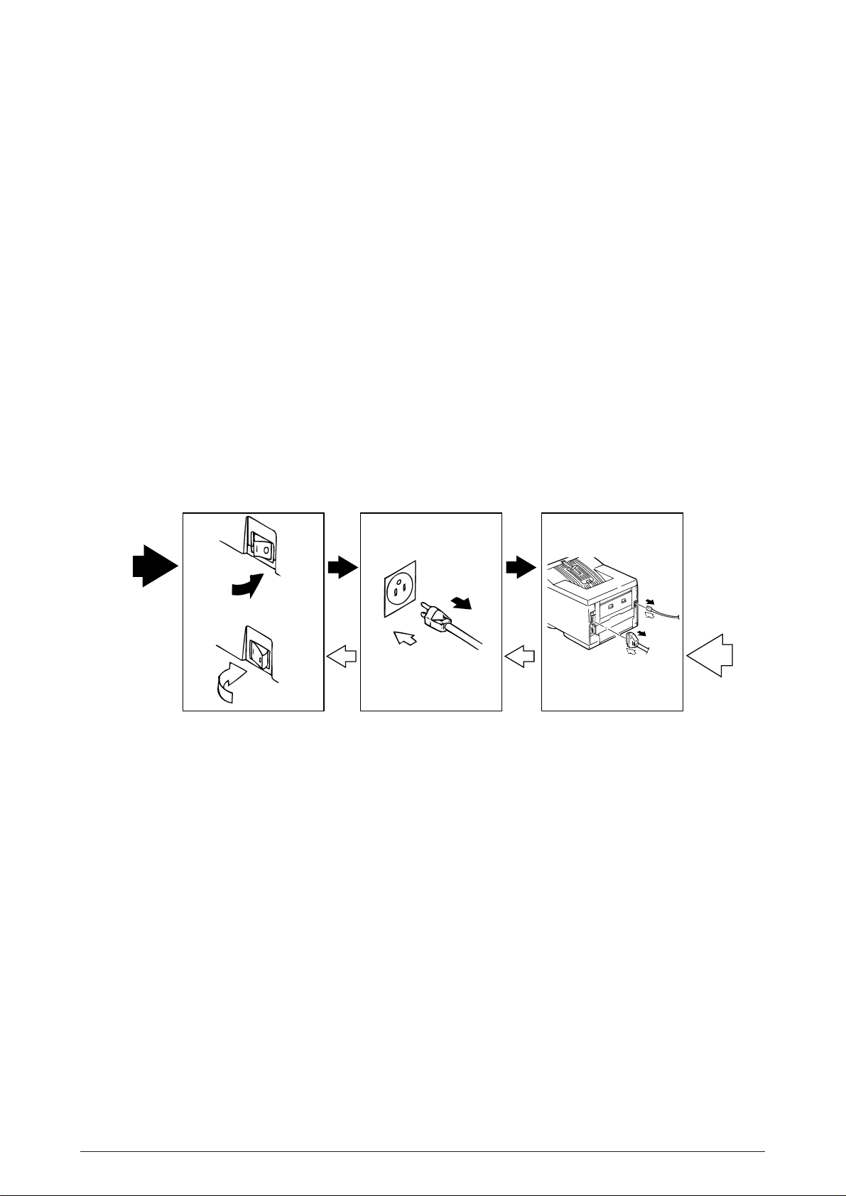
3.1 Precautions for Parts Replacement
(1) Before starting parts replacement, remove the AC cable and interface cable.
(a) Remove the AC cable in the following procedure:
i) Turn off ("o") the power switch of the printer
ii) Disconnect the AC inlet plug of the AC cable from the AC receptacle.
iii) Disconnect the AC cable and interface cable from the printer.
(b) Reconnect the printer in the following procedure.
i) Connect the AC cable and interface cable to the printer.
ii) Connect the AC inlet plug to the AC receptacle.
iii) Turn on ("l") the power switch of the printer.
Disconnect
OFF
ON
Connect
(2) Do not try disassembly as long as the printer is operating normally.
(3) Do not remove unnecessary parts: try to keep disassembly to a minimum.
(4) Use specified service tools.
(5) When disassembling, follow the determined sequence. Otherwise, parts may be damaged.
(6) Since screws, collars and other small parts are likely to be lost, they should temporarily be
attached to the orginal positions.
(7) When handling ICs such as microprocessors, ROM and RAM, and circuit boards, do not wear
gloves that are likely to generate static electricity.
(8) Do not place printed circuit boards directly on the equipment or floor.
40930701TH DRAFT Vesion 52 /
Page 53

[Service Tools]
Table 3-1 shows the tools required for field replacement of printed circuit boards and units.
Table 3-1 Service Tools
No.
1
2
3
4
5
6
7 1
8
9
No. 1-100 Philips
screwdriver
No. 2-200 Philips
screwdriver, Magnetized
No. 3-100 screwdriver
No. 5-200 screwdriver
Digital multimeter
Pliers
Handy cleaner
LED Head cleaner
P/N 4PB4083-2248P1
Connector remover
P/N 4PP4076-5395P1
Q' ty Place of use RemarksService Tools
1
2~2.5 mm screws
1
3~5 mm screws
1
1
1
1
1
Cleans LED head
Disconnect connector
1
10
Holder-TR Eject
P/N 40596701
1
For removing
ROLLER-Transfer
40930701TH DRAFT Vesion 53 /
Page 54

3.2 Parts Layout
Face-up stacker Assy
Cover-Rear
Frame-OP panel Assy
ROLLER-Transfer
Cover-Frame
Plate-Shield
Cover-Side(I/F)
Main Control Board
(Board-FFF)
Cover-Side(R)
Contact Assy
Cover-Side(L) Assy
Base Unit
CASE Assy-Cassette
Manual Feed Assy
Figure 3-1
40930701TH DRAFT Vesion 54 /
Page 55

Feed Unit-FRONT
HEAT-Assy
Motor-Main
Toner Cartridge
(Type 7)
ID Unit
(Type 7)
ROLLER
Assy-Feed
GUIDE-Assy-Eject
LED HEAD
Stacker Cover
FRAME-Main
DC Fan Motor
Figure 3-2
40930701TH DRAFT Vesion 55 /
Page 56

Power Supply Unit
(120V/230V)
FILM-Insulation
FRAME Assy-Hopping
Power Supply Unit
(High Voltage)
ROLLER Assy-Feed
GUIDE Assy-Cassette(L)
Board PXC
GUIDE
Assy-Cassette(R)
PLATE-Bottom
Figure 3-3
40930701TH DRAFT Vesion 56 /
Page 57

Photo sensor
Motor
Solenoid Assy
Control board
(Board-LEX)
Connector
(IMSA-9714N-14A)
Photo sensor
Figure 3-4
40930701TH DRAFT Vesion 57 /
Page 58

3.3 How to Change Parts
Printer Unit
Face-up Stacker Assy
Contact Assy
OP Panel Assy
Paper Cassette,
ROLLER Ass-Feed,
ROLLER-Assy-Hopping
Transfer Roller/TR Gear/
TR Bearing
Duplex Unit
(3.3.1)
(3.3.2)
(3.3.4)
(3.3.19)
(3.3.21)
(3.3.31)
DC fan motor
HEAT Assy
Board-FFF
Feeder Unit-Front
Frame Assy-Separation
Board-LEX
Connector
(3.3.3)
(3.3.14)
(3.3.5)
(3.3.10)
(3.3.20)
(3.3.32)
(3.3.33)
Roller Assy-BK
Stacker Assy, Damper Arm,
Cover Rear
Roller Assy-Regist
Motor-Main
Roller Assy-Feed
Photo Sensor
Solemnoid Assy
Motor
(3.3.16)
(3.3.6)
(3.3.11)
(3.3.12)
(3.3.17)
(3.3.34)
(3.3.35)
(3.3.36)
Sensor Stacker Full
Cable Cover
Damper
LED Head
Guide Assy-Eject
EP Lock Shaft
Lever Assy-Out Sensor
Toner Sensor Lever
Paper Sensor Lever
Inlet Sensor Lever
Power Supply Unit
Lever-Paper end &
Paper near end
(3.3.7)
(3.3.8)
(3.3.9)
(3.3.18)
(3.3.13)
(3.3.22)
(3.3.23)
(3.3.24)
(3.3.25)
(3.3.26)
(3.3.27)
(3.3.28)
Roller Feed (C)
Gudie Assy-Cassette(L)
Gudie Assy-Cassette(R)
(3.3.15)
(3.3.29)
(3.3.30)
This section explains how to change parts and assemblies appearing in the disassembly diagram
below.
40930701TH DRAFT Vesion 58 /
Page 59

3.3.1 Face -up Stacker Assy
(1) Turn off the AC Power Switch and unplug the AC Power Cord from the outlet.
(2) Disconnect the Interface Cable 1.
(3) Open the face-up stacker assy 2, unhook the right and left projections, and then remove
the face-up stacker assy 2.
2
1
40930701TH DRAFT Vesion 59 /
Page 60

3.3.2 Contact Assy
(1) Open the stacker assy 1 and unscrew 2 screw 2 to remove the assy -side (L)3.
(2) Unscrew 2 screws 4 and remove the plate (contact) 5 and contact Assy 6.
Note! Don’t deform the electrode plates of the contact assy 6.
2
1
3
Unlock this part before removing
6
6
5
4
40930701TH DRAFT Vesion 60 /
Page 61

3.3.3 DC Fan Motor
(1) Remove the cover assy-side (L). [See 3.3.2 (1)]
(2) Remove the DC fan motor 1 by pulling out the connector of DC fan motor 1.
1
40930701TH DRAFT Vesion 61 /
Page 62

3.3.4 OP Panel Assy
(1) Disconnect the Interface cable 1.
(2) Open the stacker assy 2, unscrew 2 screws 3 and remove the cover side (I/F) 4.
(3) Remove 2 screws 5 and flexible cable 6 to remove the operator panel assy 7.
5
7
6
3
4
2
1
40930701TH DRAFT Vesion 62 /
Page 63

3.3.5 Board-FFF
(1) Remove the operator panel assy and cover side (I/F). [See 3.3.4]
(2) Unscrew 2 screws 1 and remove the cover side (R) 2.
(3) Unscrew 16 screws 3 and remove plate-shield 4.
(4) Unscrew 3 screws 5 and 2 screws 6, unplug all the connectors 7 , and remove Board-FFF
8.
4
6
5
5
8
7
7
3
5
7
1
2
40930701TH DRAFT Vesion 63 /
Page 64

3.3.6 Stacker Assy, Damper Arm, Cover Rear
(1) Remove the face-up stacker assy. [See 3.3.1]
(2) Remove the cover-side (L). [See 3.3.2 (1)]
(3) Remove the OP panel assy. [See 3.3.4]
(4) Remove the Board-FFF. [See 3.3.5]
(5) Loosen 2 screws, unlock the both sides latches and remove the cover rear A.
(6) Unscrew 2 screws 1 and cover frame 2.
(7) Unscrew 3 screws 3 and remove the plate assy-side (R) 4.
(8) Remove the lever back up release 5 and unlock the engagement of the projection on the
right side of gear at the right side of stacker cover.
(9) Remove a screw 6 and washer 7, and then remove the stacker assy 8.
(At this time, the damper arm 9 can also be detached simultaneously.)
A
8
7
9
5
1
2
6
3
0
4
40930701TH DRAFT Vesion 64 /
Page 65

3.3.7 Sensor Stacker Full
(1) Turn the AC power switch off. Unplug the AC power cord from the outlet.
(2) Remove the Stacker assy. [See 3.3.6]
(3) Remove four screws 1. Remove stacker mount 2 by releasing the tabs at position 2A .
(4) Remove Sensor stacker full 3 by releasing speading the plastic tabs on each side of sensor
Assy 3 and lifting switch from cover.
2A
3
1
2A
1
2
40930701TH DRAFT Vesion 65 /
Page 66

3.3.8 Cable cover (guide film)
(1) Turn the AC power switch off. Unplug the AC power cord from the outlet.
(2) Remove the stacker Assy. [See 3.3.6]
(3) Unscrew 2 screws 1 release tabs at portion 1A . Remove cable cover 2, guide film 3.
1A
2
3
1
Note: Use care when replacing cable cover. Do not pitch, crimp, or cut cables or
protective sheet.
40930701TH DRAFT Vesion 66 /
Page 67

3.3.9 Damper
(1) Remove the damper arm. [See 3.3.6]
(2) Unscrew 2 screws 1 and remove the two damper 2.
1
2
40930701TH DRAFT Vesion 67 /
Page 68

3.3.10 Feeder Unit-Front
2
(1) Open the manual feed assy 1 and release both right and left parts by pulling out the
engagements on the lower part.
(2) Stand the manual feed assy 1 on end and unhook the engagements with both right and left
manual feed hopper stays.
(3) Remove the OP panel assy. [See 3.3.4]
(4) Unscrew 5 screws 2 and remove the feeder unit-front 3.
2
2
3
1
40930701TH DRAFT Vesion 68 /
Page 69

3.3.11 Roller Assy-Regist
(1) Remove the feeder unit-front. [See 3.3.10]
(2) Remove an E-ring 3, gear assy-clutch 4, and four screws 1 in this order, and lifting out the
roller assy-regist 2.
1
1
2
3
4
40930701TH DRAFT Vesion 69 /
Page 70

3.3.12 Motor -Main
(1) Remove the stacker assy. [See 3.3.6]
(2) Remove the feeder unit-front. [See 3.3.10]
(At this point, the manual feed assy has not to be removed.)
(3) Remove the DC fan motor. [See 3.3.3]
(4) Remove the contact assy. [See 3.3.2]
(5) Remove the plate-FG (F) 1.
(6) Remove the TR gear 2 and roller transfer 3.(Use Holder-TR Eject F for the removal.)
(7) Unscrew 7 screws 4 and remove the main frame 5.
(8) Unlock latches at two points of the lever back up release 6 and pull out it in right direction.
(9) Unhook the EP lock spring 7 and remove the EP lock lever 8.
(10) Take off the E ring 9 and remove the plate-FG (1st ) 0 and gear assy-clutch A.
(11) Unlock 2 latches to remove the motor assy-main B and idle gear C.
(12) Unscrew 2 screws D and remove the motor -main E .
40930701TH DRAFT Vesion 70 /
Page 71
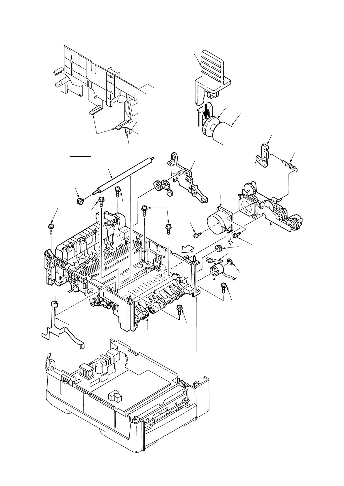
Latch
F
2
3
8
4
View A
2
4
3
4
5
4
6
D
View A
A
E
0
4
C
9
7
B
D
1
4
5
40930701TH DRAFT Vesion 71 /
Page 72
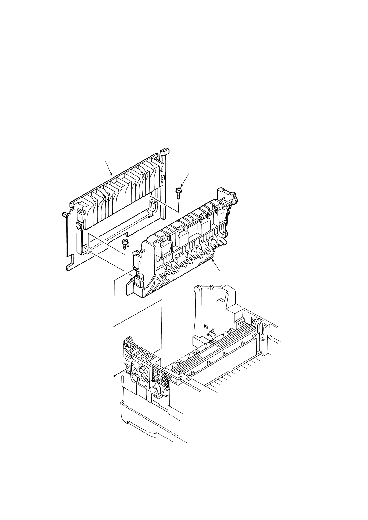
3.3.13 Guide Assy-Eject
(1) Remove the lever back up release. [See 3.3.12(8)]
(But the roller transfer/feeder unit front/plate-FG have not be removed)
(2) Loosen 2 screws 1, unlock the both side’s latches and remove the cover rear 2. [See 3.3.6
(5)]
(3) Unlock the latches on both sides of the guide assy-eject 3 and lifting it out.
2
1
1
3
40930701TH DRAFT Vesion 72 /
Page 73

3.3.14 Heat Assy
(1) Remove the cover assy-side (L). [See 3.3.2 (1)]
(2) Unplug the connectors 1, 2.
(3) Unscrew 4 screws 3 and remove the heat assy 4 in the direction of the arrow by lifting the
right side first.
Note ! • As the heat assy 4 becomes high temperature soon after the power is turned
off, start the work after it cools off sufficiently.
• Carry out a reset of the counter after the replacement. (See Section 4.2)
3
3
2
4
1
40930701TH DRAFT Vesion 73 /
Page 74

3.3.15 Roller feed (C)
(1) Remove the guide assy-eject. (See 3.3.13)
(But roller transfer/feeder unit-front/plate-FG(F) have not be removed)
(2) Remove the gear roller (C) 1 and bush 2, warp (a) part of the plate-FG (BK) 3. Take off
the carrier bearing 4 and remove the roller feed (c) 5 in the direction of the arrow.
Note ! Be careful not to deform (a) part of the plate-FG (BK) 3.
1
2
5
(a)
3
4
40930701TH DRAFT Vesion 74 /
Page 75

3.3.16 Roller Assy-BK
(1) Remove the heat Assy. [See 3.3.14]
(2) Remove the lever back up release. [See 3.3.12 (8)]
(3) Unlock the engagement with the plate-FG (BK) 1 and lift out the roller heat assy 2.
2
1
40930701TH DRAFT Vesion 75 /
Page 76

3.3.17 Roller Assy-Feed
(1) Remove the feeder unit -front. [See 3.3.10]
(2) Remove the roller assy-feed 1 by unlocking a latch.
1
40930701TH DRAFT Vesion 76 /
Page 77

3.3.18 LED Head
(1) Remove the stacker assy 1. [See 3.3.6]
(2) Unplug the PC connector 2 and 2 LED cables 3 from the LED head 4.
(3) Open the hooks of the cover stacker 1 in the direction of the arrow and remove the LED head
4.
(4) Pull out the head spring 5 from the post.
Note: Don't remove two LED cable 3 from the PC connector 2.
1
2
5
5
3
4
40930701TH DRAFT Vesion 77 /
Page 78

3.3.19 Paper cassette, ROLLER Ass-Feed, ROLLER-Assy-Hoppibg
(1) Pull out the case assy -cassette 1 from the printer.
(2) Remove the ROLLER Ass-Feed 2 and remove the ROLLER-Assy-Hopping 3.
3
2
1
40930701TH DRAFT Vesion 78 /
Page 79
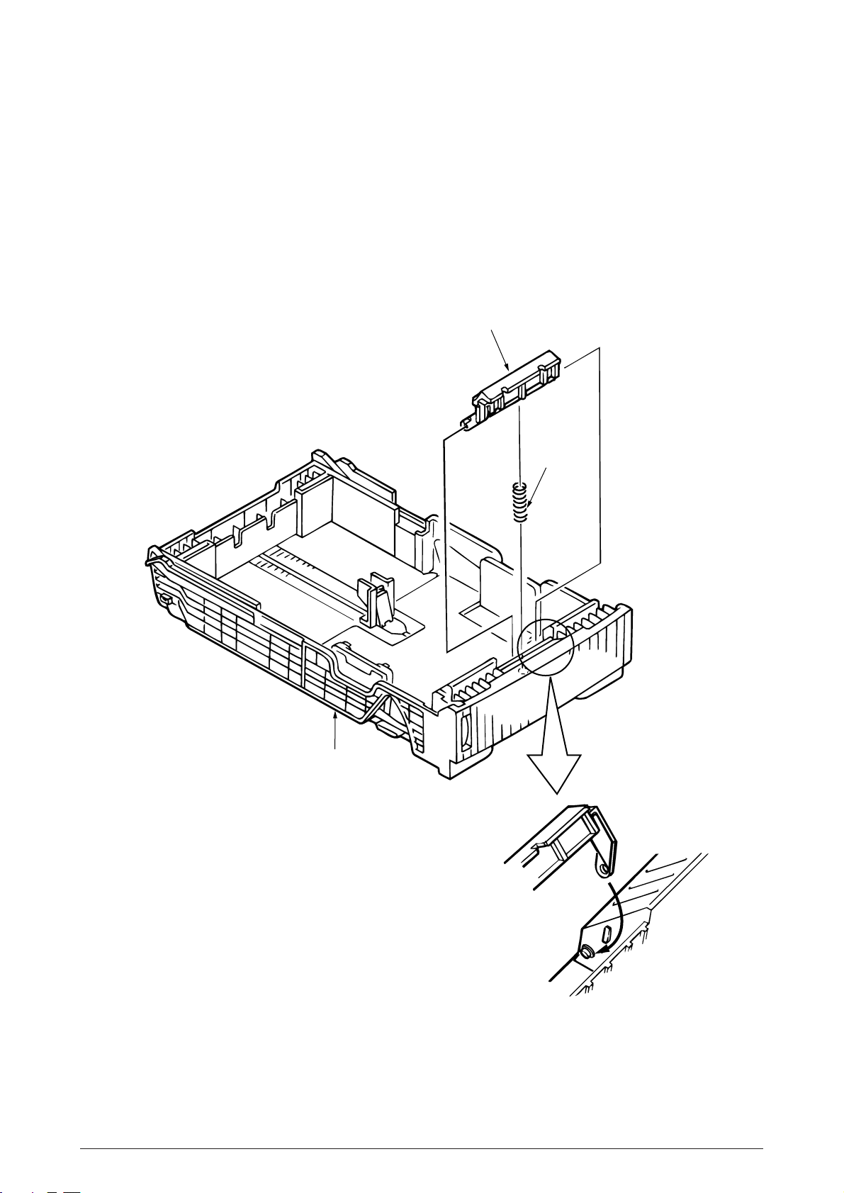
3.3.20 Frame Assy-Separation
(1) Turn the AC power switch off. Unplug the AC power cord from the outlet.
(2) Pull out the case Assy-Cassette 1 from the printer.[See 3.3.19(1)]
(3) Release two locks and remove frame assy-separation 2. (At this time, coil spring 3 is also
remove. Be careful not to lose this spring.)
2
3
1
Insert 1 so as to pass the both arms of 1
behind two latches inside the alcove of 2 unit.
40930701TH DRAFT Vesion 79 /
Page 80

3.3.21 Transfer Roller/TR Gear/TR Bearing
(1) Open the stacker cover .
(2) Unlock the lock by lifting the TR gear 1 to remove the TR gear 1 and roller transfer 2.
(Use the Holder-TR Eject 5 for the removal.)
Note ! Don’t place the removed roller transfer directly on the desk and so on. When
placing it, lay a paper and the like under it.
(3) Remove right and left, 2 bearings 3 from the frame-main by sliding them inside while
pushing them. At this time, 2 transfer springs R 4 would be detached simultaneously.
1
5
1
2
3
4
2
4
2
3
1
40930701TH DRAFT Vesion 80 /
Page 81

3.3.22 EP lock shaft
2
(1) Turn the AC power switch off. Unplug the AC power cord from the outlet.
(2) Remove Frame-Main [See.3.3.12(7)]
(3) Remove screw 1. Turn EP lock lever (L) Assy 2 in the direction of arrow A .
(4) Remove spring 3.
(5) Drop EP lock shaft 4 down and turn in the direction of arrows B and remove it.
1
3
4
A
B
40930701TH DRAFT Vesion 81 /
Page 82

3.3.23 LEVER Assy- Out Sensor
(1) Turn the AC power switch off. Unplug the AC power cord from the outlet.
(2) Remove the frame main [See 3.3.12(7)]
(3) Press the clamp part of LEVER Assy.- Out Sensor 1. Remove the LEVER Assy.-Out Sensor
1 by pushing it upward from the lower side.
1
1
40930701TH DRAFT Vesion 82 /
Page 83

3.3.24 Toner sensor lever
(1) Turn the AC power switch off. Unplug the AC power cord from the outlet.
(2) Remove the frame main [See 3.3.12(7)]
(3) Squeeze the clamp part of toner sensor lever 1 and remove the toner sensor lever 1 by
pushing it upward from the lower side.
1
1
40930701TH DRAFT Vesion 83 /
Page 84

3.3.25 Paper sensor lever
(1) Turn the AC power switch off. Unplug the AC power cord from the outlet.
(2) Remove the frame main [See 3.3.12(7)]
(3) Squeeze the clamp part of the paper sensor lever 1 and remove the paper sensor lever 1
by pushing it upward from the lower side.
1
1
40930701TH DRAFT Vesion 84 /
Page 85

3.3.26 Inlet sensor lever
(1) Turn the AC power switch off. Unplug the AC power cord from the outlet.
(2) Remove the frame main [See 3.3.12(7)]
(3) Squeeze the clamp part of two inlet sensor levers 1. Remove the inlet sensor levers 1 by
pushing them downward.
1
1
1
40930701TH DRAFT Vesion 85 /
Page 86

3.3.27 Power supply unit
(1) Turn the AC power switch off. Unplug the AC power cord from the outlet.
(2) Remove the frame main [See 3.3.12(7)]
(3) Unscrew 2 screws 1 and remove the BRACKET-AC 2.
(4) Unscrew 10 screws 3 and remove the connector 6 remove the Power supply unit [AC-
DC(120/230V)] 4 and Power supply unit (High voltage) 5.
2
3
3
4
3
6
3
5
1
40930701TH DRAFT Vesion 86 /
Page 87

3.3.28 Lever-Paper end & Lever-Paper near end
(1) Turn the AC power switch off. Unplug the AC power cord from the outlet.
(2) Remove the frame main [See 3.3.12(7)]
(3) Remove screw 1 and then remove the PLATE-Base 2.
(4) Remove two Spacer-Cord(KGPS-5RF) 4 and then remove FILM-Insulation 4.
(5) Remove four screws 5 and then remove the FRAME ASS-Hopping 6.
(6) Remove the GEAR-Z58 9 and GEAR-Z42 8.
(At this time, the ADF Bearing 0 can also be detached simultaneously.)
(7) Remove the GEAR-Z38 D, ADF Bearing E, ROLLER-Guide F and SHAFT Hopping G and
Bracket-Sub roller R.
(At this time, the Kock Pin H can also be detached simultaneously.)
(8) Remove two screws 7 and then remove the SPRING-Release A and then remove the
LEVER-Sub roller B and PLATE-Hopping C.
(9) Remove the GEAR-Planet(Z28) I, Plate-Planet J, BRACKET-Spring (Sub) K and
SPRING-Sub ROLLER L.
(10)Press the clamp part of Lever-Paper end M and Lever-Paper near end N. Remove the
Lever-Paper end M and Lever-Paper near end N by pushing it upward from the FRAME
Hopping R.
(11)Remove the Connection Cord-Wire O and TR-23-11-14 R CORE P together.
(12)Remove two Photo Sensor Q.
40930701TH DRAFT Vesion 87 /
Page 88

7
5
8
6
1
3
2
4
Q
N
R
5
O
F
P
C
Q
M
D
B
A
E
J
0
F
H
R
9
G
K
L
I
40930701TH DRAFT Vesion 88 /
Page 89

3.3.29 Guide Assy-Cassette (L)
(1) Turn the AC power switch off. Unplug the AC power cord from the outlet.
(2) Remove Frame Main [See 3.3.12(7)]
(3) Remove PLATE-Base and FRAME Assy Hopping [See 3.3.28 (5)]
(4) Unscrew two screw 1 and then remove Guid Assy-Cassette (L) 2.
(5) Remove SPRING-Sheet 3 and then remove LINK-Sheet 4 and pull block 5.
(Pay attention the direction of hook of SPRING-Sheet 3.)
(6) Remove spring 6 and then remove cassette stopper 7.
(7) Remove screw 8 from LINK-Sheet 4 and then remove link support 9 and Roller-link 0.
(8) Remove Earth Plate L A and Plate-Earth (link) B.
6
7
A
2
B
5
8
9
3
0
4
1
40930701TH DRAFT Vesion 89 /
Page 90

3.3.30 Guide Assy-Cassette (R)
(1) Turn the AC power switch off. Unplug the AC power cord from the outlet.
(2) Remove Frame Main [See 3.3.12(7)]
(3) Remove PLATE-Base and FRAME Assy Hopping [See 3.3.28 (5)]
(4) Unscrew two screw 1 and then remove Guid Assy-Cassette (R) 2.
(5) Remove SPRING-Sheet 3 and then remove LINK Sheet 4 and pull block 5.
(Pay attention the direction of hook of SPRING-Sheet 3.)
(6) Remove spring 6 and then remove cassette stopper 7.
(7) Remove screw 8 from LINK-Sheet 4 and then remove link support 9 and Roller-link 0.
(8) Unscrew two screws A and remove the Square shaped connector (176496-1) B and
Nylon Connector Cord C and TR-23-11-R CORE D.
(9) Unscrew two screws E and remove the two Plate Earth (Bottom) F.
(10) Unscrew two screws G and remove the Square shaped connector (5-176496-1) H and
Connection Cord Wire I and TR-23-11-R CORE J.
(11) Unscrew a screw K and remove the Detector spring L.
(12) Unscrew a screw M and remove the Board PXC N.
40930701TH DRAFT Vesion 90 /
Page 91

1
E
E
F
G
J
M
N
I
K
H
L
7
6
3
8
9
5
F
2
D
C
4
B
0
A
40930701TH DRAFT Vesion 91 /
Page 92

3.3.31 Removing/Installing Duplex Unit
Removing Duplex Unit
(1) Power Off and remove the Paper-Cassette from 1st tray.
(2) Remove the LEVER-Release (Dup) from the boss of the Hopping Frame.
B
Boss
LEVER-Release (Dup)
B
Release Release
LEVER-Release (Dup)
B - B View
(3) Rotate the LEVER-Lock (Dup) in the direction of the arrow to release the Lock.
Connector
LEVER-Lock (Dup)
Turn
LEVER-Lock (Dup)
(4) Pull the Duplex Unit out of the unit.
Connector
LEVER-Release (Dup)
Printer
Groove
Duplex Unit
40930701TH DRAFT Vesion 92 /
Page 93

Installing Duplex Unit
(1) Hold the LEVER-Lock (Dup) in horizontal lock position.
Then insert the Duplex Unit along the groove, up to accord both rear faces between printer
and Duplex Unit.
Printer
Groove
Note:
Before setting it to the
unit, make sure that the
LEVER-Release (Dup) is
Duplex Unit
locked at the angle as
shown Locking point
Connector
Locking point
LEVER-Release (Dup)
Note:
Printer and Duplex Unit will connect automatically with built-in connector.
LEVER-Release (Dup)
(2) Lock the Duplex Unit to the printer by turning the LEVER-Lock (Dup) to the next locking
position as below.
Connector
LEVER-Lock (Dup)
(3) From front side of printer, snap fit LEVER-Release (Dup) into the boss in Hopping Frame.
B
Boss
B
Snap Fit Snap Fit
LEVER-Release (Dup)
Snap Fit
into Boss
B - B View
LEVER-Release (Dup)
(4) After installing Duplex Unit, put back the Paper Cassette into 1st Tray.
40930701TH DRAFT Vesion 93 /
Page 94

3.3.32 Board-LEX
(1) Remove two LEVER-Lock (DUP) 1 by rotating them in the arrow direction.
(2) Unscrews five screws 2 to remove the bracket 3.
(3) Unlatch all the nails and unplug all the connectors 4 to remove the Board-LEX 5.
[Note : When installing the Board-LEX, install it, positioning earth plate over the PCB.]
2
3
2
PLATE-Earth (F/R)
1
3
4
5
5
4
1
1
40930701TH DRAFT Vesion 94 /
Page 95
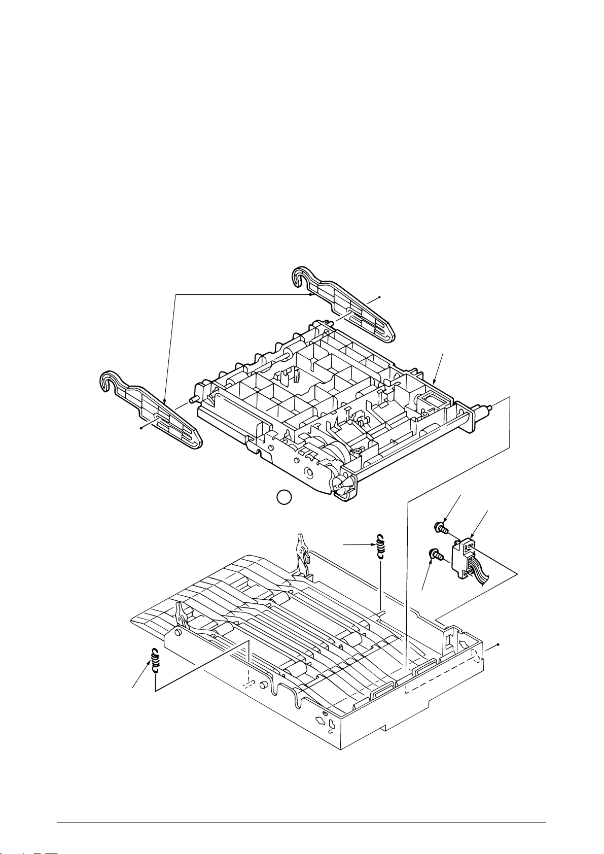
3.3.33 Connector (IMSA-9714N-14A)
(1) Remove two LEVER-Release (DUP) 1.
(2) Take away two SPRING-Support 2 to remove FRAME-MAIN (DUP) 3.
(Remove the FRAME-MAIN (DUP) by lifting in up from A side)
(3) Unscrew two screws 4 to unplug the Connector (IMSA-9714N-14A) 5.
1
3
2
A
4
5
2
4
40930701TH DRAFT Vesion 95 /
Page 96

3.3.34 Photo Sensor
(1) Remove the Frame-Main (DUP) (see section 3.3.2).
(2) Release the lock to remove two SPRING-Lock (frame) 1 and two LEVER-Lock Assy 2.
(3) Pull out four SHAFT-Pinch 3 and remove four ROLLER-Pinch 4 and eight SPRING-Pinch
(u) 5.
(4) Release the lock to remove two BRACKET-Pinch 6 , and two SPRING-Pinch(R) 9.
(5) Release the lock to remove LEVER Sensor (D-IN) 0 and SPRING-Sensor A.
(6) Unplug the Connection Code-Wire B and remove Photo Sensor C.
5
4
1
2
5
1
3
4
5
3
7
8
6
5
9
7
8
6
9
6
8
Film-Pinch (R)
C
B
7
A
Note
: It should not become a state such as of dotted line
from the results of installation.
40930701TH DRAFT Vesion 96 /
0
Page 97

3.3.35 SOLENOID Assy
(1) Remove the Frame-Main (DUP) (See section 3.3.2).
(2) Release the lock to remove Two LEVER Sensor (F/R) 1 and two SPRING-Sensor (F/R) 2.
(3) Unplug the Connection Code-Wire 3 and remove Photo Sensor 4.
(4) Take away the SPRING-SL 5 and two screws 6 to remove SOLENOID Assy 7.
3
4
7
5
1
2
2
View
6
7
View
6
40930701TH DRAFT Vesion 97 /
Page 98

3.3.36 Motor
1
(1) Remove the Frame-Main (DUP) (See section 3.3.2).
(2) Unscrew two screws 1 to remove PLATE-Earth (F/R) 2.
(3) Unscrew three screws 3 to remove PLATE-Earth (F/R-2) 4.
(4) Disengage the latch to remove the Bearing L 5 , GEAR-Z40S8 6 , Bearing 7and ROLLER-
(5) Unscrew the screw 0 to remove the PLATE-Earth (BTM) A.
(6) Disengage the latch and remove two PULLEY-MX25 B , Mini-Pitch Belt C and two Bushes
(7) Disengage the latch to remove the Bearing Feed E and ROLLER Feed (F) F.
(8) Remove the E-Ring G and Bush H.
(9) Unscrew two screws I to remove the GEAR Assy J.
(10) Unscrew two screws N to remove Motor O.
Feed (RV) 8.
(At this time, Knock Pin 9 can be removed simultaneously.)
D.
(At this time, the GEAR-Z40S6 K , Knock Pin L and ROLLER-Feed (R) M can be removed.)
E
3
4
I
3
K
F
L
M
2
D
8
9
B
C
5
N
0
G
H
J
6
O
A
7
40930701TH DRAFT Vesion 98 /
Page 99

5. PERIODIC MAINTENANCE
5.1 Periodic Replacing Part
As specified below, the parts shall be replaced periodically.
Part name Condition for replacement Cleaning Remarks
• Toner cartridge 5,000 • LED head. Consumables
• Image drum cartridge 30,000 • LED head. Consumables
• Heat Assy 200,000 Maintenance Kit
• Transfer Roller 200,000 Maintenance Kit
• Back up Roller Assy 200,000 Maintenance Kit
• Feed Roller Assy 200,000 Maintenance Kit
• Hopping Roller Assy 200,000 Maintenance Kit
• Regist Paper dust.
• Regist Paper dust.
• Separation Frame Assy 200,000 Maintenance Kit
[Note: Maintenance Kit shall be replenished by user;s calling to serviceman.]
5.2 Cleaning
Remove any toner and dust. Clean inside and around the printer with a piece of cloth when
necessary. Use the handy cleaner (VACCUM) for cleaning the printers interior.
Note:
Do not touch image drum, LED lens array, and LED head connector block.
5.2.1 Cleaning of LED lens array
Clean the LED lens array or replace the toner cartridge when white lines or stripes (void, light
printing) are generated vertically down the page.
Note:
The LED lens array must be cleaned with an LED head cleaner.
White lines or stripes
(void, light printing)
40930701TH DRAFT Vesion 118 /
Page 100

5.2.2 Cleaning the Plastic Film
(1) Open the stacker assy and remove I/D unit.
(2) After cleaning LED head, wipe off the paper powder by LED LENS CLEANER and remove
the paper powder.
Plastic Film
(3) Take the remove paper powder out of the printer unit in such a way as not to spill it, and then
waste it.
40930701TH DRAFT Vesion 119 /
 Loading...