

Page 1
Page 2

Page 3

◆ Contents ◆
Name of Parts ............................... 2
Power .............................................. 6
Computer Connection ................... 8
Paper Setting ................................. 9
Ribbon Setting ..........………….. 11
Does not print correctly .............. 13
When error light is ON ............... 14
Failure? .................. .............. ....... 15
Page 4
Name of Parts
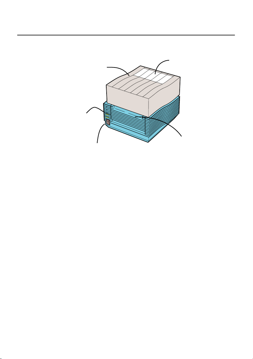
■Front View
Top cover
Paper check
window
Operation switch
Power switch
Front cover
■Top cover .................... Open thi s co ver when you s et t he p ape r.
■ Power switch .............. Press this sw it c h to t u rn O N/O F F t he p ri n te r.
■ Paper check window ... To check the status of p ap e r.
■ Front cover ................. Open this cover to refill or set DIP-SW.
■ Operation switch
2
• POWER .... When you turn on the power, the green light lights up. Refer to
“Starting/Power”.
• ERR OR ..... When a n error occu r s , t he red light t u rns ON. Re fe r t o
“When error light is ON”.
• ONLINE ... When the green light is ON, the printer can receive data. When
the light is OFF, the printer cannot receive.
• [ ONLINE ] button ... Pres s this bu tton to s top rece iving da ta. Resume by
pressing this button again. If this button is pressed
while printing, the printing is suspended. To resume
printing, press this button again.
• [FEED] but t on ........ When you press this button in the o ffline st at e, y o u
can feed paper. If you turn on the power of the printer
while you keep pressing this button, you can print out
the printer status.
Page 5
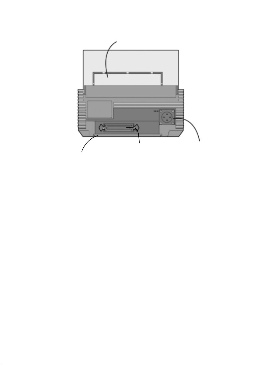
Back View
I/F Cover
Fanfold paper set in place
Optional interface
Connecter
■Power Connector ... Connects AC adapter.
■Optional interface Connecter ... Connects computer.
■Fanfold Paper set in place ...
Open this to use fanfold paper.To open the folder,
remove the Top Cover and release.
■I/F Cover ... It removes by exchange of an I/F board.
※
Handling of an I/F Cover:
Please close with an I/F Cover after shutting off a power supply and
attaching or removing an I/F board, in case an I/F Cover is opened.
Power
Connector
3
Page 6
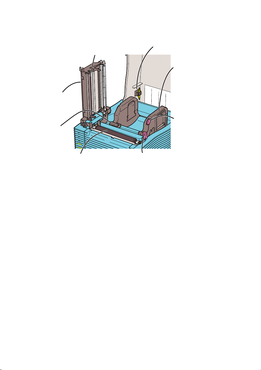
■ Top Cover Open
Thermal head
Head
Sensor
Platen roller
Head Open/Close lever
■ Paper holder ... When you use a roll paper, set the paper here. You can
adjust the width according to the paper size.
■ Paper holder slide lever .. Press this lever to ad ju st th e pape r holde r wid th.
■ Head ................ Open th i s p a rt t o re fill p ap e r.
■ Head Open/Close lever .. Press this to open the head.
■ Thermal head .... This is the printing area. Please keep this part clean.
■ Platen roller ...... Thi s i s th e pa rt t ha t fee d s pa pe r. Please ke ep th is pa rt
clean.
■ Sensor ................ Paper travels over this .
■ Driver for darkness adjustment ... This is used to change the print darkness.
4
Driver for darkness
adjustment
Paper holder
Paper holder
slide lever
Page 7
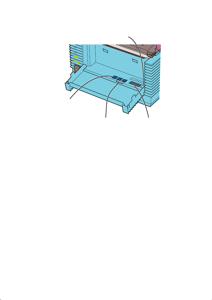
■ Front Cover Open
Error number display
Print darkness
adjustment volume
■ Print darkness adjustment volume .. You can finely adjust the darkness that
■ Sensor level ...... Do not use this . Only for used by service pe r s on nel.
■ DIP-SW ............ Appropriate s e t t i n gs are set ac c ording to yo u r printer
system environment. You can change the settings. See the
manual for details.
■ Error number display .. When the error light is ON, ch eck th e di sp layed
Sensor level DIP-SW
is set in the Printer Setting screen. See
the manual for details.
number. This number represents the reason of the
error. See the manual for details.
5
Page 8
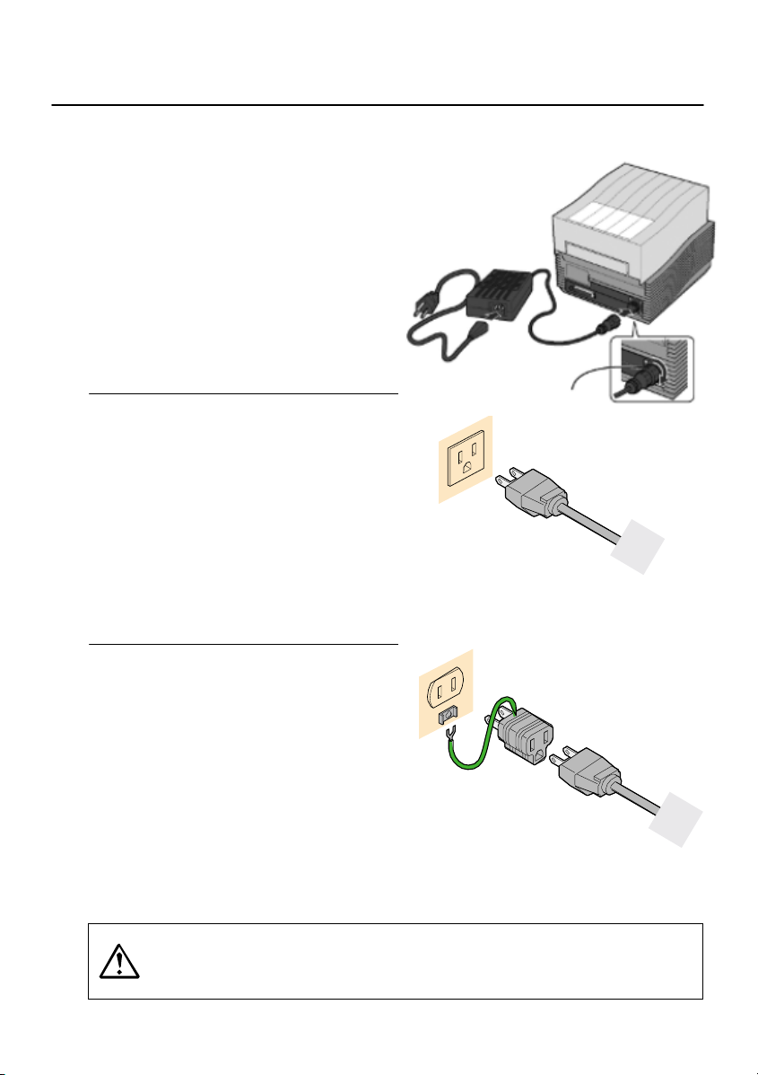
Power
Cable Connection
1 Connect the power cable with the
main unit and AC adapte r as shown
in the figure. When you insert the
AC adapter in the main unit, set the
stopper firmly.
2 Plug in t he po wer cable to th e outlet.
3 Use a Two-prong adapter if only a
two-prong outlet is available.
1 Connect the power cable with the
main unit and AC adapte r as shown
in the figure. When you insert the
AC adapter in the main unit, set the
stopper firmly.
2 Plug in t he po wer cable to th e outlet.
3 Use a Two-prong adapter if only a
two-prong outlet is available.
1 Connect the power cable with the
main unit and AC adapte r as shown
in the figure. When you insert the
AC adapter in the main unit, set the
stopper firmly.
2 Plug in t he po wer cable to th e outlet.
3 Use a Two-prong adapter if only a
two-prong outlet is available.
Always make sure to ground the power cable to the ground connector,
otherwise electric shock may result. Construct the ground facility if it
is not available.
6
Stopper
Page 9
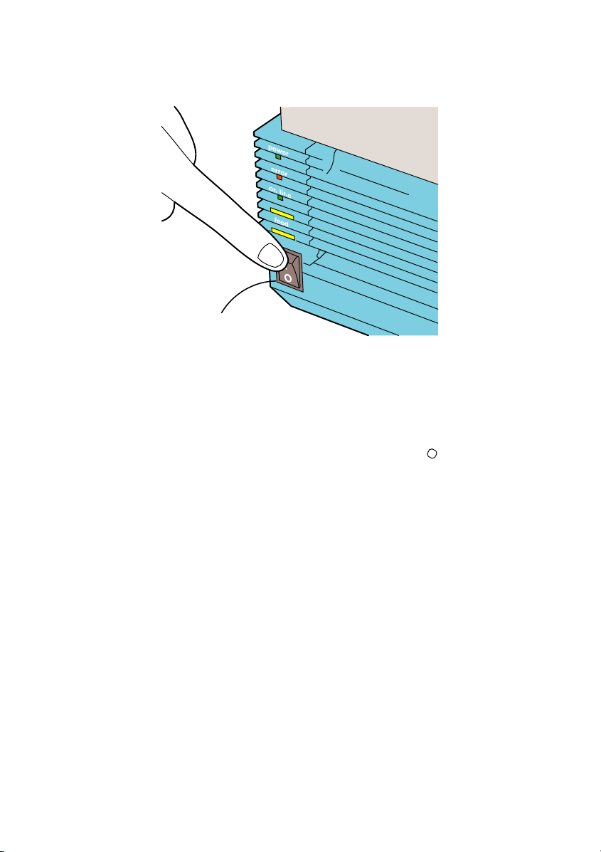
Power Switch
Press the power swit ch at the fron t side of the main unit in the “|” dire ction.
* When you turn on the power, the POWER light lights up. Please confirm
this.
When you turn off the printer, flip the switch to the “ ” direction.
Power Switch
7
Page 10
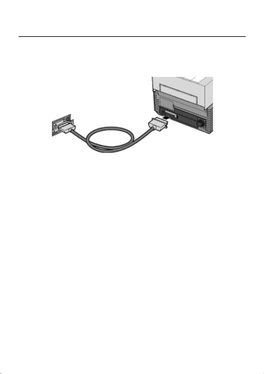
Computer Connection
Connection example using Bi-directional parallel interface
Use [Bi-directional parallel interface (sold sepa ra tel y)].
This printer operates by being connected to a computer.
interface cable connecting the bi-directional parallel interface connector at
the rear panel of the printer.
* If you are using a different optional interface board, refer to the instructions of
8
Turn off the power of the printer and connect to the computer with an
its “Optional Interface”.
Page 11
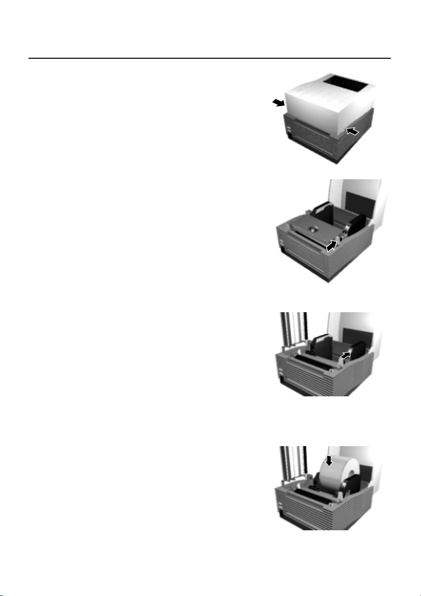
Paper Setting
1 Confirm the [PUSH ] mark on the
Left/Right side of the main unit.
While depressing the mark on the cover, open
the Top cover
2 Press the Head Open/Close lever to
the direction as shown in Figure.
Confirm that the head is detached from the
platen roller part, then lift the head in the
direction as shown in the Figure.
3 While pressing the paper holder slide
leve r, adjust the paper holder to the paper
size.
4 Set the paper on the paper holder .
9
Page 12
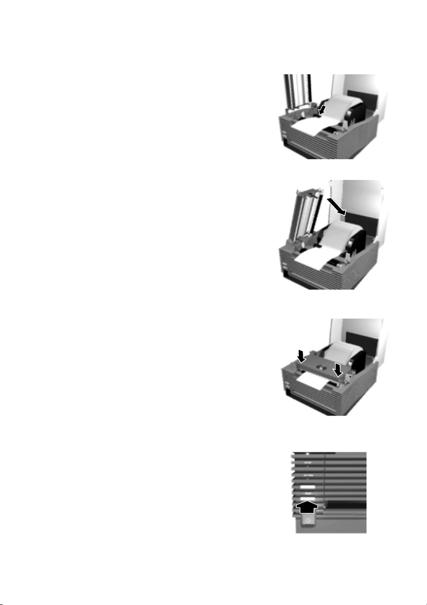
5 Pull the paper,then pass under the sensor.
6 Close the head to the home position.
7 Depress the [PUSH] mark with finger
until fixed fi rmly.
Close the Top cover.
8 Set the top of the paper by pressing the
[FEED] button.
Finally, press the [ONLINE] button to change
10
the online status.
Page 13
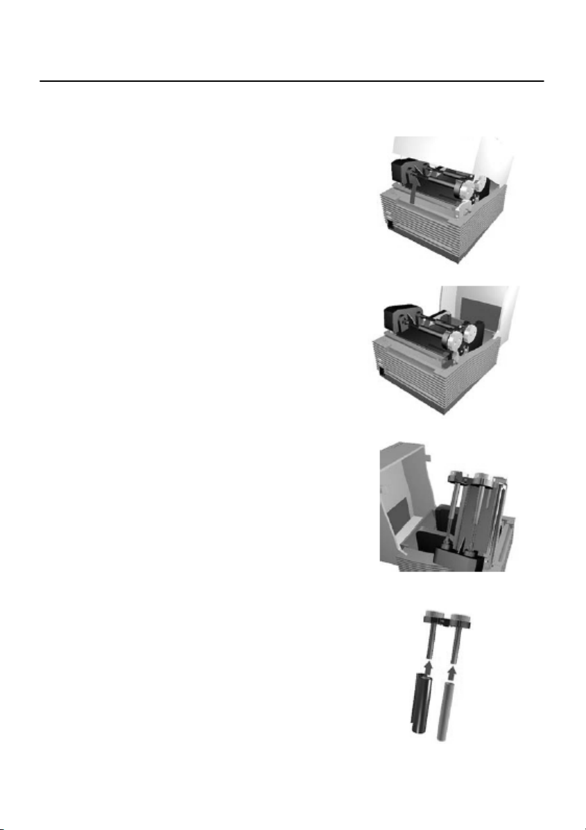
Ribbon Setting
Thermal Transfer model OKI POS T400/T410 only.
1 Confirm the [PUSH] mark on the Left/Right
side of the main unit.
While depressing the mark on the cover, open
the Top cover.
2 Press the Head Open/Close lever to the
direction as shown in Figure.
Confirm that the head is detached from the
platen roller part, then lift the head in the
direction as shown in the Figure.
3 While pressing the Ribbon Core Lock
button, pull the ribbon core from the unit.
* The roller is also opened.
4 Insert the ribbon core in the ribbon supply
spindle on the opposite side.
And insert the empty ribbon core to the
ribbon rewind spindle on this side.
Please confirm the direction of the roll.
Insert the guide part of the ribbon core in the
slot of the ribbon unit side and return the
ribbon core to the unit.
11
Page 14
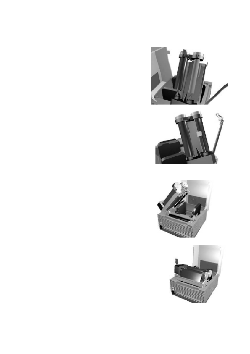
5 Please insert the ribbon core and fix
firmly.
* There are three depths according
to the ribbon width.
*Insert in the specified position by
pressing the Lock button.
6 Pull out the ribbon along with the
head. Stick the edge of the ribbon
into the empty ribbon core by using
a tape.
Rotate the Ribbon Roll-up Knob
in the clockwise direction and the
wind up the ribbon several times.
7 Close the roller to the home position.
Close the head to the home position.
8 Depress the [Push] mark with finger
until fixed firmly. Close the Top
cover.
*When replace the ribbon the next time, keep
the ribbon core and replace the used ribbon
with new ribbon.
12
Page 15

Does not print correctly
Print error
• Paper set correctly?
➞
• Platen roller clean?
➞
• Paper replenished regularly?
➞
• Is the data or signal from the computer is correct?
➞
• Setting of paper position correction adjusted?
➞
• Label adhered the sensor?
➞
• Sensor clean?
➞
Paper is fed but does not print
• Thermal head clean? No label is adhered to the head?
➞
Kit.
➞
➞
Printout is not clear
• Print darkness appropriate?
➞
➞
Please set the paper correctly.
If the platen roller is not clean, clean it using the Cleaning Kit
(refer to the manual).
If the edge of the paper does not set regularly, the paper cannot
be fed to the printer correctly. Please be sure to use paper.
Please turn off and on the power of the printer. Confirm the
contents and communication conditions of the software in your
computer.
Please correct the position. See the manual for de tails.
Remove the label and clean up.
Clean the sensor.
If the thermal head is not clean, clean the head using the Cleaning
If a label is adhered to the thermal head, remove the label.
Please make sure not to remove the label using metal instruments such
as a screw driver. It may damage the thermal head.
If the stick from the label is adhered to the thermal head, clean
it using the Cleaning Kit.
You can adjust the print darkness (refer to the manual).
You can adjust the Print Darkness Adjustment Volume (refer to
the manual) by changing the printer darkness settings in the Printer
Setting screen. When you use the Print Darkness Adjustment Volume, be
sure to read the manual.
13
Page 16
• Paper set correctly?
➞
Please confirm that the paper is set correctly.
• Platen roller clean?
➞
If the platen roller is not clean, clean the platen roller using the
Cleaning Kit (refer to the manual).
• Thermal head clean? No label is adhered to the head?
➞
If the thermal head is not clean, clean the head using the
Cleaning Kit.
➞
If a label is adhered to the thermal head, remove the label.
Please make sure not to remove the label using metal instruments such
as a screw driver. It may damage the thermal head.
➞
If the stick from the label is adhered to the thermal head,
clean it by using the Cleaning Kit.
• Paper clean?
➞
Please use a clean paper.
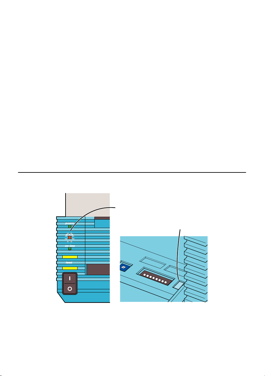
When error light is ON
Error light
When the error light is ON or flashing, there is an error.
Confirm the error number that is shown on the Error Number Display. This
number indicates the reason of the error.
See the manual for details.
14
[ERROR] light
Error Number Display
Page 17

Failure?
Please confirm the following before you decide it’s a mechanical failure.
POWER light is not ON even if you turn on the machine.
AC adapter and power cable are plugged in the outlet correctly?
➞
AC adap ter is plu gg e d in to the m ain unit c orrectly?
➞
No damages of the power cable?
➞
➞
Is there any electricity come from the outlet?
➞
Fuse or breaker is not functioning?
➞
AC adapter light is ON?
➞
Plug in AC adapter and power cable into the outlet correctly.
Plug in the AC adapter to the main unit power connector firmly.
Replace the power cable. A new power cable is available in
your local dealer.
Please do not use other power cables.
Confirm the power source of the outlet.
If there is no problem with the power source, confirm that electricity is
supplied to your building.
Please also check for any power cut possibility.
If so replace the fuse and turn on the breaker.
If it is not ON, confirm the power source.
15
Page 18

Page 19

 Loading...