

Page 1

OKIPAGE 8c Plus
/ OKICOLOR 8
Color LED Page Printer
MAINTENANCE
MANUAL
ODA/OEL/INT
1999.8.12 Rev.1
41057601TH Rev.1 1 / 199
Page 2
Rev.No. Date Corrected items Person in
No. Page Description of change change
1 1999.8.12 ISSUE E4 Yamazaki
41057601TH Rev.1 2 /
Page 3

PREFACE
This maintenance manual provides procedures and techniques for the troubleshooting, maintenance, and
repair of OKICOLOR 8 / OKIPAGE 8c Plus.
This manual is written for maintenance personnel, but it should always be accompanied with the
OKICOLOR 8 / OKIPAGE 8c Plus User’s Manual for procedures for handling and operating OKICOLOR
8 / OKIPAGE 8c Plus. For repairing each component of OKICOLOR 8 / OKIPAGE 8c Plus, see the
Troubleshooting manual.
[Notices]
The contents of this manual are subject to change without prior notice.
Although reasonable efforts have been taken in the preparation of this manual to assure its accuracy, this
manual may still contain some errors and omissions. OKI will not be liable for any damage caused or
alleged to be caused, by the customer or any other person using this maintenance manual to repair,
modify, or alter OKICOLOR 8 / OKIPAGE 8c Plus in any manner.
[Warning]
Many parts of OKICOLOR 8 / OKIPAGE 8c Plus are very sensitive and can be easily damaged by improper
servicing. We strongly suggest that OKICOLOR 8 / OKIPAGE 8c Plus be serviced by OKI’s authorized
technical service engineers.
41057601TH Rev.1 3 /
Page 4

CONTENTS
1. SPECIFICATIONS ............................................................................................ 7
1.1 Basic System Configuration............................................................................................. 7
1.2 Printer Specifications .......................................................................................................8
1.3 Option Specifications ....................................................................................................... 9
1.4 Basic Specifications....................................................................................................... 10
2. OPERATION................................................................................................... 12
2.1 Main Control Board (PCE PCB)..................................................................................... 13
2.2 Engine Control Board (PX4 PCB) .................................................................................. 16
2.3 Power/Units.................................................................................................................... 17
2.4 Mechanical Processes................................................................................................... 18
2.4.1 Electrophotographic processing mechanism .................................................... 19
2.4.2 Paper running process ..................................................................................... 25
2.5 Sensors.......................................................................................................................... 34
2.5.1 Paper related sensors ...................................................................................... 34
2.5.2 Other sensors ................................................................................................... 35
2.6 Correction of Color Deviation......................................................................................... 36
2.7 Transfer Control according to Environmental Changes
(Room Temperatures and Relative Humidities)............................................................. 36
2.8 Form Jam Detection....................................................................................................... 37
2.9 Cover Opening............................................................................................................... 37
2.10 Toner Low Detection...................................................................................................... 38
2.11 Page Size Detection ...................................................................................................... 39
2.12 Power-on Processing..................................................................................................... 40
2.12.1 Self-diagnostic test ........................................................................................... 40
3. PARTS REPLACEMENT................................................................................41
3.1 Precautions for Parts Replacement ............................................................................... 41
3.2 Parts Layout................................................................................................................... 43
3.3 How to Change Parts..................................................................................................... 47
3.3.1 Cover Assy Rear .............................................................................................. 48
3.3.2 Motor-Fan (80-25) ............................................................................................ 49
3.3.3 Paper Eject Assy .............................................................................................. 50
3.3.4 Cover Assy Stacker, Guide Eject FD Assy....................................................... 51
3.3.5 Frame Assy Upper............................................................................................ 52
3.3.6 Plate Support Assy ........................................................................................... 53
3.3.7 Limiter 2way (L), (R) / Plate Guide (L) , (R) ...................................................... 54
3.3.8 Cover ............................................................................................................... 55
3.3.9 PCB Assy : PCE ............................................................................................... 56
3.3.10 Motor Fan (CU)................................................................................................. 57
3.3.11 PXF PCB/PX4 PCB .......................................................................................... 58
3.3.12 Gear Heat Assy ................................................................................................ 59
3.3.13 Main Motor (A), (B) Assy .................................................................................. 60
3.3.14 Gear One-way (Z30)......................................................................................... 61
3.3.15 Motor Assy BT .................................................................................................. 62
3.3.16 Power Supply Unit, Holder Inlet, Sheet Insulation............................................ 63
3.3.17 Sensor Assy Box Toner .................................................................................... 64
3.3.18 Square-shaped Connector ............................................................................... 65
41057601TH Rev.1 4 /
Page 5

3.3.19 Hopping Motor .................................................................................................. 66
3.3.20 Gear One-way .................................................................................................. 67
3.3.21 Feeder Unit Front ............................................................................................. 68
3.3.22 Manual Feed Hopper Assy ............................................................................... 69
3.3.23 Guide Paper Input Assy.................................................................................... 70
3.3.24 Two Lever Input Sensors, Lever 2nd Feed Sensor .......................................... 71
3.3.25 Roller Registration, Roller Assy Hopping ......................................................... 72
3.3.26 Roller Hopping.................................................................................................. 73
3.3.27 PXU PCB/PXM PCB, Lever Resist Sensor ...................................................... 74
3.3.28 Paper End Lever............................................................................................... 75
3.3.29 PCO PCB (Operator Panel).............................................................................. 76
3.3.30 Holder Gear Toner Assy................................................................................... 77
3.3.31 Plate Latch Lever (FD), Spring Latch Lever (FD) ............................................. 78
3.3.32 Belt Cassette Assy ........................................................................................... 79
3.3.33 High Voltage Power Supply Unit, Bracket HV (BT) Assy ................................. 80
3.3.34 Eraser Bracket Assy, Eraser Bracket (KCM) Assy ........................................... 81
3.3.35 Shaft Link.......................................................................................................... 82
3.3.36 Contact (BL-R) Assy, Contact (CL-R) Assy ...................................................... 83
3.3.37 Contact (BL-L) Assy, Contact (CL-L) Assy ....................................................... 84
3.3.38 Contact SB Assy............................................................................................... 85
3.3.39 PXC PCB .......................................................................................................... 86
3.3.40 Heat Unit Assy.................................................................................................. 87
3.3.41 Oil Roller Assy .................................................................................................. 88
3.3.42 Lever Lock Heat (L)/(R), Guide Side Heat, Spring Lock................................... 89
3.3.43 PXL PCB .......................................................................................................... 90
3.3.44 Heat Unit Guide Assy ....................................................................................... 91
3.3.45 Holder LED Assy, LED Head............................................................................ 92
4. ADJUSTMENTS ............................................................................................. 93
4.1 Maintenance Modes and Their Functions...................................................................... 93
4.1.1 User maintenance mode .................................................................................. 93
4.1.2 System maintenance mode .............................................................................. 95
4.1.3 Engine maintenance mode ............................................................................... 97
4.2 Adjustments after Parts Replacement ......................................................................... 100
4.2.1 Confirm the LED head driving time................................................................. 100
4.2.2 Color deviation correction............................................................................... 102
5. PERIODIC MAINTENANCE ......................................................................... 105
5.1 Periodically Replaced Parts ......................................................................................... 105
5.2 Cleaning....................................................................................................................... 105
5.3 Cleaning the LED Lens Array ...................................................................................... 105
5.4 Cleaning the Pickup Roller........................................................................................... 105
6. TROUBLESHOOTING PROCEDURES ....................................................... 106
6.1 Troubleshooting Tips ................................................................................................... 106
6.2 Points to Check before Correcting Image Problems.................................................... 106
6.3 Tips for Correcting Image Problems ............................................................................ 106
6.4 Preparation for Troubleshooting .................................................................................. 107
6.5 Troubleshooting Flow................................................................................................... 107
6.5.1 LCD status message/trouble list..................................................................... 107
6.5.2 LCD message troubleshooting ....................................................................... 116
6.5.3 Image troubleshooting .................................................................................... 129
41057601TH Rev.1 5 /
Page 6

7. WIRING DIAGRAM...................................................................................... 146
7.1 Resistance Check ........................................................................................................ 146
7.2 Program/Font ROM Location ....................................................................................... 150
8. Parts List...................................................................................................... 154
Appendix A CENTRONICS PARALLEL INTERFACE.................................... 175
Appendix B HIGH CAPACITY SECOND PAPER FEEDER ........................... 179
1. OUTLINE ......................................................................................................179
1.1 Functions ..................................................................................................................... 179
1.2 External View and Component Names........................................................................ 179
2. MECHANISM DESCRIPTION ...................................................................... 180
2.1 General Mechanicsm................................................................................................... 180
2.2 Hopper Mechanism...................................................................................................... 181
3. PARTS REPLACEMENT..............................................................................182
3.1 Precautions Concerning Parts Replacement............................................................... 182
3.2 Parts Layout................................................................................................................. 184
3.3 Parts Replacement Methods........................................................................................ 185
3.3.1 Idle rollers ....................................................................................................... 186
3.3.2 AOLT-PCB...................................................................................................... 187
3.3.3 Hopping motor ................................................................................................ 188
3.3.4 Feed roller ...................................................................................................... 189
3.3.5 Hopping roller ................................................................................................. 190
3.3.6 Side frame (L) assy ........................................................................................ 191
3.3.7 Side frame (R) assy........................................................................................ 192
4. TROUBLESHOOTING.................................................................................. 193
4.1 Precautions Prior to the Troubleshooting..................................................................... 193
4.2 Preparations for the Troubleshooting........................................................................... 193
4.3 Troubleshooting Method .............................................................................................. 194
4.3.1 LCD Status Message List ............................................................................... 194
4.3.2 Troubleshooting Flow ..................................................................................... 195
5. CONNECTION DIAGRAM............................................................................ 196
5.1 Interconnection Diagram.............................................................................................. 196
5.2 PCB Layout.................................................................................................................. 197
6. PARTS LIST ................................................................................................. 198
41057601TH Rev.1 6 /
Page 7
M
M M
M M
M M
M
LED head
Discharging indicators
Centronics
interface
HSP
Controller
Junction board
Pulse motors
Engine controller
Low-voltage
power unit
Fixing unit
High-voltage
power unit
Second tray
Belt unit
<Sensors, switches, and thermistors>
Paper width sensor
Form size detector (4 bits)
Form end sensor
FF form end
FF home switch
Form feed sensor 1
Form feed sensor 2
Write sensor
Ejection sensor
Toner Low (Y.M.C.K)
EP Up/Down (Y.M.C.K)
Waste toner sensor
Resist Up/Down
Cover open switch (High-voltage
interlock switch)
Heater temperature thermistor
Backup temperature thermistor
Environment temperature sensor
Environment humidity sensor
Oil Roller switch
Fixing unit interlock switch
Waste toner box switch
Y-EP unit M-EP unit C-EP unit B-EP unit
PSIMM
x2
interface
SIMM
x4
interface
Y EP M EP C EP K EP BELT HEATER REGIST FF
Operator panel
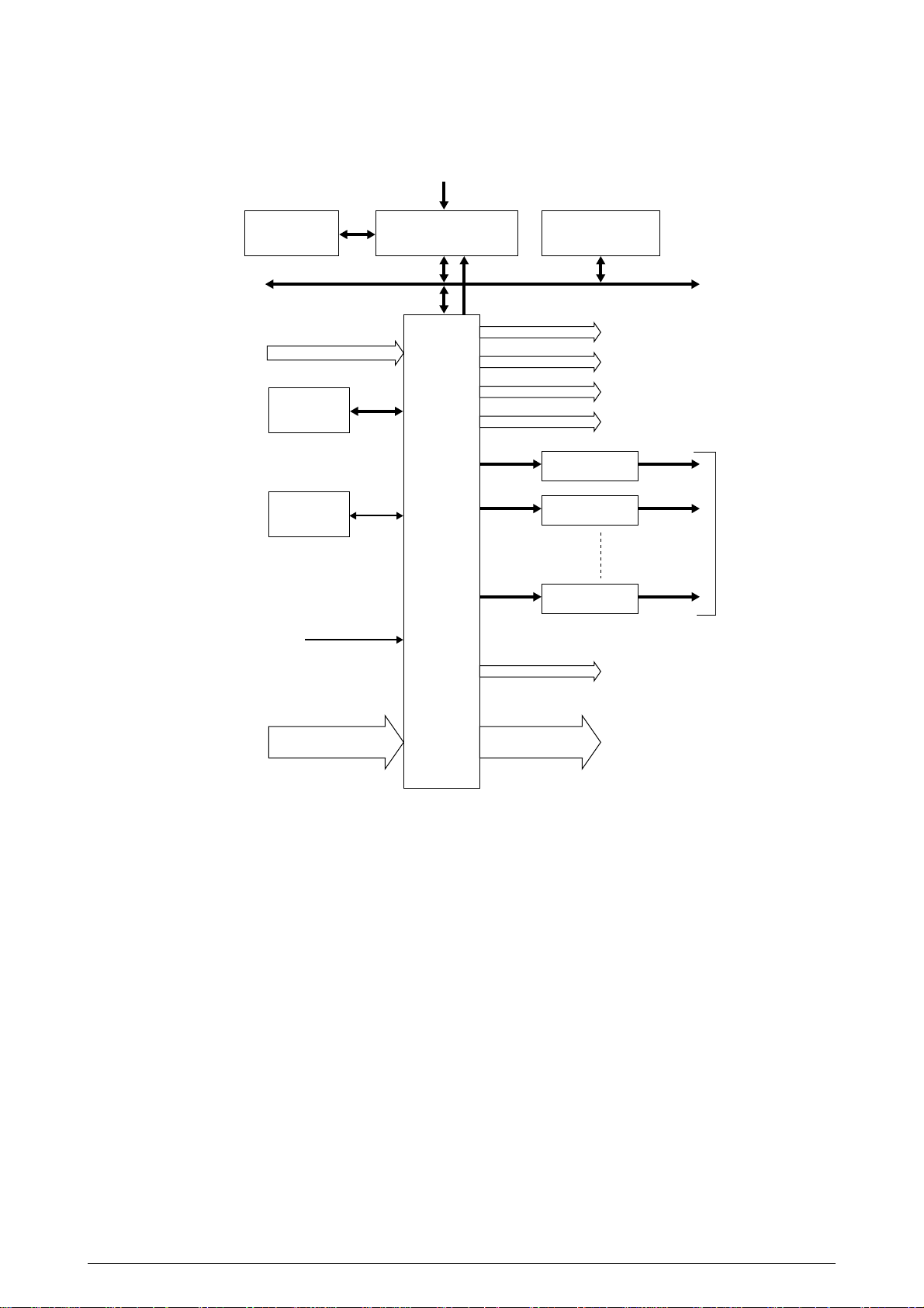
1. SPECIFICATIONS
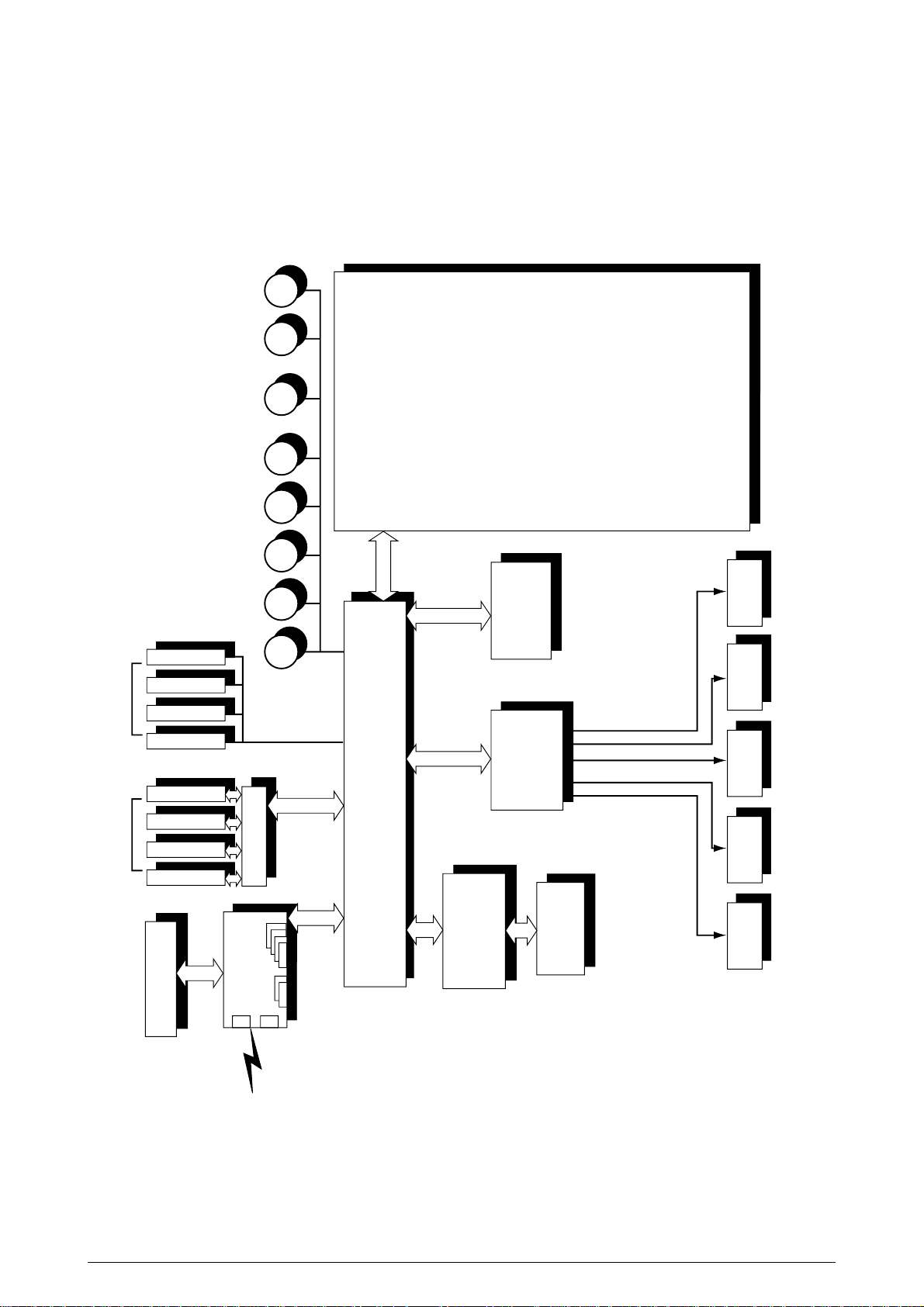
1.1 Basic System Configuration
The basic system configuration of OKICOLOR 8 / OKIPAGE 8c Plus is illustrated in Figure 1.1.
Figure 1.1
41057601TH Rev.1 7/
Page 8
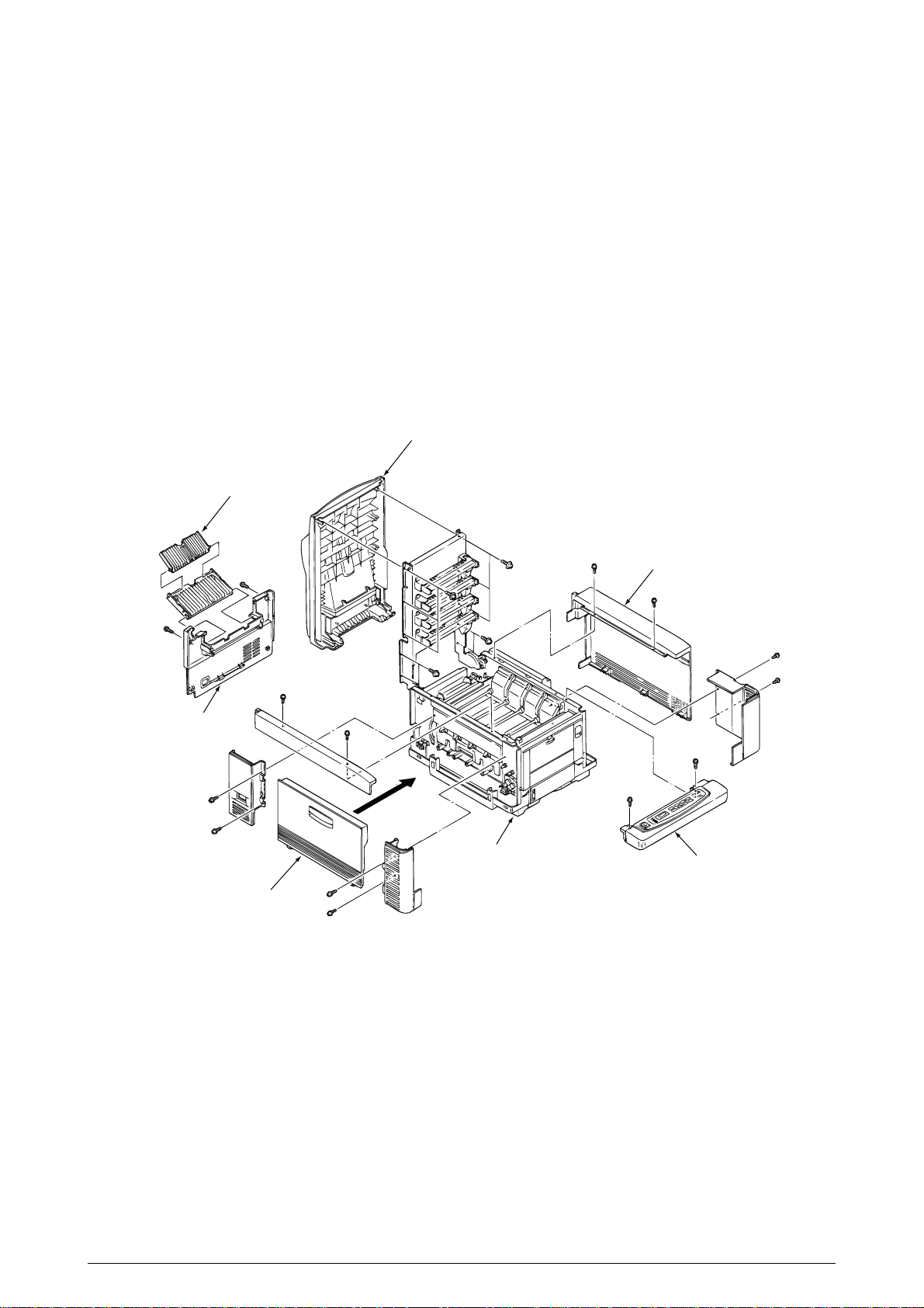
1.2 Printer Specifications
This printer unit is composed with the following hardware.
• Electro-photographric processor
• Paper feeder
• Controller (CU part / PU Part)
• Operator panel
• Power board (High voltage part / PU part)
Figure 1-2 show the printer unit configuration.
Face-up Stacker Assy
Stacker Cover Assy
I/F Cover Assy
Rear Cover
Side Cover (L) Assy
Base Unit
Figure 1.2
Operator Panel Assy
41057601TH Rev.1 8/
Page 9
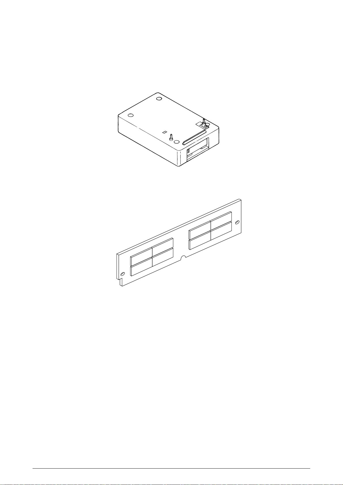
1.3 Option Specifications
Options available for OKICOLOR 8 / OKIPAGE 8c Plus are as follows.
(1) 2nd-Feeder
(2) RAM SIMM module (72 pin SIMM, 4MB/8MB/16MB/32MB)
* Make sure to use a set of 2 of the same volume size modules.
41057601TH Rev.1 9/
Page 10

1.4 Basic Specifications
(1) Dimensions
Width: 18.8" (478mm) Length: 24.5" (622mm) Height: 15.6" (396mm)
(2) Weight
Approx. 48kg (106lbs)
(3) Form
Type: Ordinary paper (Hammermill 24lbs) and OHP (Only CG3710)
Recommended paper (for color printing)
Color laser paper (20lb to 24lbs)
Note: The printout color tones are dependent upon the whiteness of the print
paper
Sizes: Letter, Legal (13"or 14"), Executive, A4, A5, B5, and A6 (1st tray and front feeder)
Reams: 1st tray 20lbs to 28lbs
2nd tray 20lbs to 28lbs
Front feeder 20lbs to 44lbs
(5) Printing speed
8 pages per minute (5 pages per minute: OHP/ 34lbs ~44lbs, 123g/m2~166g/m2)
(6) Resolution
600 dots per inch x 600 dots per inch
(7) Input voltage
120VAC +5.5%, -15%
230VAC ±10%
(8) Power consumption
Peak W
Typical operation W
Idle W
Power-save mode W
(9) Frequency
50Hz or 60Hz +2%, -2%
(10) Noises
Operating: 54dB (without 2nd tray), 55dB (with 2nd tray)
Standby: 45dB
Power-saving: 43dB
(11) Expendibles and service life
Toner cartridge: Approx. 1800 pages (5% duty) (each of Y, M, C, and K)
(Approx. 1000 sheets for the first)
Image drum: Up to 12,000 pages (5% duty, continuous) (each of Y, M, C, and K)
Waste Toner Box: Up to 25,000 Sheets
(under typical printout conditions: Single images of 5% density,
equivalent to printout using 14 toner cartridges)
Oil Roller Unit: Up to 10,000 sheets (Life defined in the number of actually printed
paper sheets)
(12) Periodically-replaced parts
Heat Unit Assy: 60,000 pages
Belt Cassette Assy: 50,000 pages
41057601TH Rev.1 10/
Page 11
(13) Temperatures and relative humidities
Temperature
Temperature conditions
Temperature (in _F) Temperature (in _C) Remarks
Operating
Non-operating
Storage (1 year max.)
Delivery (1 month max.)
Delivery (1 month max.)
50 to 89.6
32 to 109.4
14 to 109.4
-20 to 122
-20 to 122
Humidity
Humidity condition
Relative humidity (%) Wet-bulb temperature Remarks
Operating
Non-operating
Storage
Delivery
20 to 80
10 to 90
10 to 90
10 to 90
for the packed unit only
10 to 32
0 to 43
-10 to 43
-29 to 50
-29 to 50
25
26.8
35
40
17_C to 27_C (for assurance
of full-color printout quality)
Power off
with drum and toner
without drum and toner and
Belt Cassette Assy
with drum and toner
50% to 70% (for assurance of
full-color printout quality)
Power off
(14) Printer life
3,000,000 (A4) pages or 5 years
41057601TH Rev.1 11/
Page 12
2. OPERATION
AC-IN AC switch
Crimp-style terminal
PXL board
PXL
Ejection sensor
LED head: Y M C K
Discharging lamp: Y M C K
Heat roller
thermistor
Backup roller
thermistor
Heater unit
SUMi card x 4
PD6 board
Y600 14P
YPOW 12P
M600 14P
MPOW 12P
C600 14P
CPOW 12P
K600 14P
KPOW 12P
HEAD1 13P HEAD2 14P HEADPOW 12P HEAD3 15P
FF form
sensor
Toner sensor x 4
ID sensor x 4
Low-voltage power supply
6P
6P'
JST3P
FAN 1
FAN 2
3P
Oil PAD MSW
FF
motor
Paper supply sensor board
FF Pos MSW
PXM board
40095001YU
REG.POS
sensor
Resist
motor
Y-IDU
motor
M-IDU
motor
C-IDU
motor
K-IDU
motor
Belt
motor
Heat
motor
PXF board
JODEN 8P
FSENS 8P
TONER
14P
PXFIF 30P
OPTION 7P
PENDTNR 6P
PX4 board
2nd tray
(option)
Form end
sensor
Waste toner
sensor
YIDREG
8P
MCKID
12P
HETBELT
8P
HEAD3
15P
HEAD2
14P
HEAD1
13P
HEADPOW
12P
FF 12P
PXFIF 30P
HVOLT 16P COVOPN 2P PSIZE 6P
High-voltage power supply
PXC board
Form size detector
Cover open
MSW
PCE
Operator
panel
PCO
board
CM
6P
PU 40P
72PX2
PS SIMM
72PX4
D-RAM SIMM
64P
OKI HSP
36P
Parallel
CUIF 40P
POWER 30P
THE.RM 6P
RSENS 7P
Interlock switch
UPDOWN
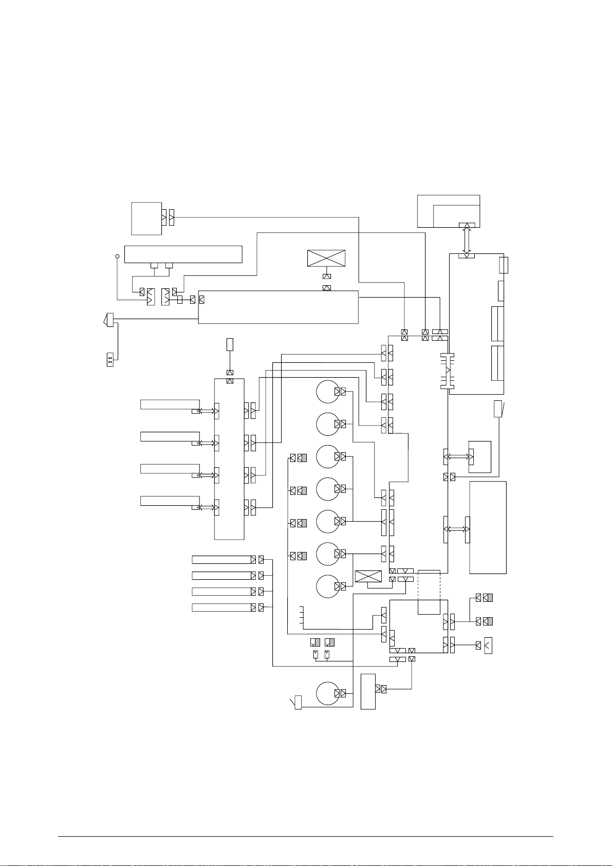
12P
OKICOLOR 8 / OKIPAGE 8c Plus is a tandem color electrophotographic page printer, using 4992LED technologies , OPC, dry single-component non-magnetic developing, roller transfer, heatcompression fixing and so on. The printing method used is a Black Writing method which applies
light beams to printout areas.
Figure 2.1 shows the functional block diagram of OKICOLOR 8 / OKIPAGE 8c Plus.
41057601TH Rev.1 12/
Figure 2.1
Page 13
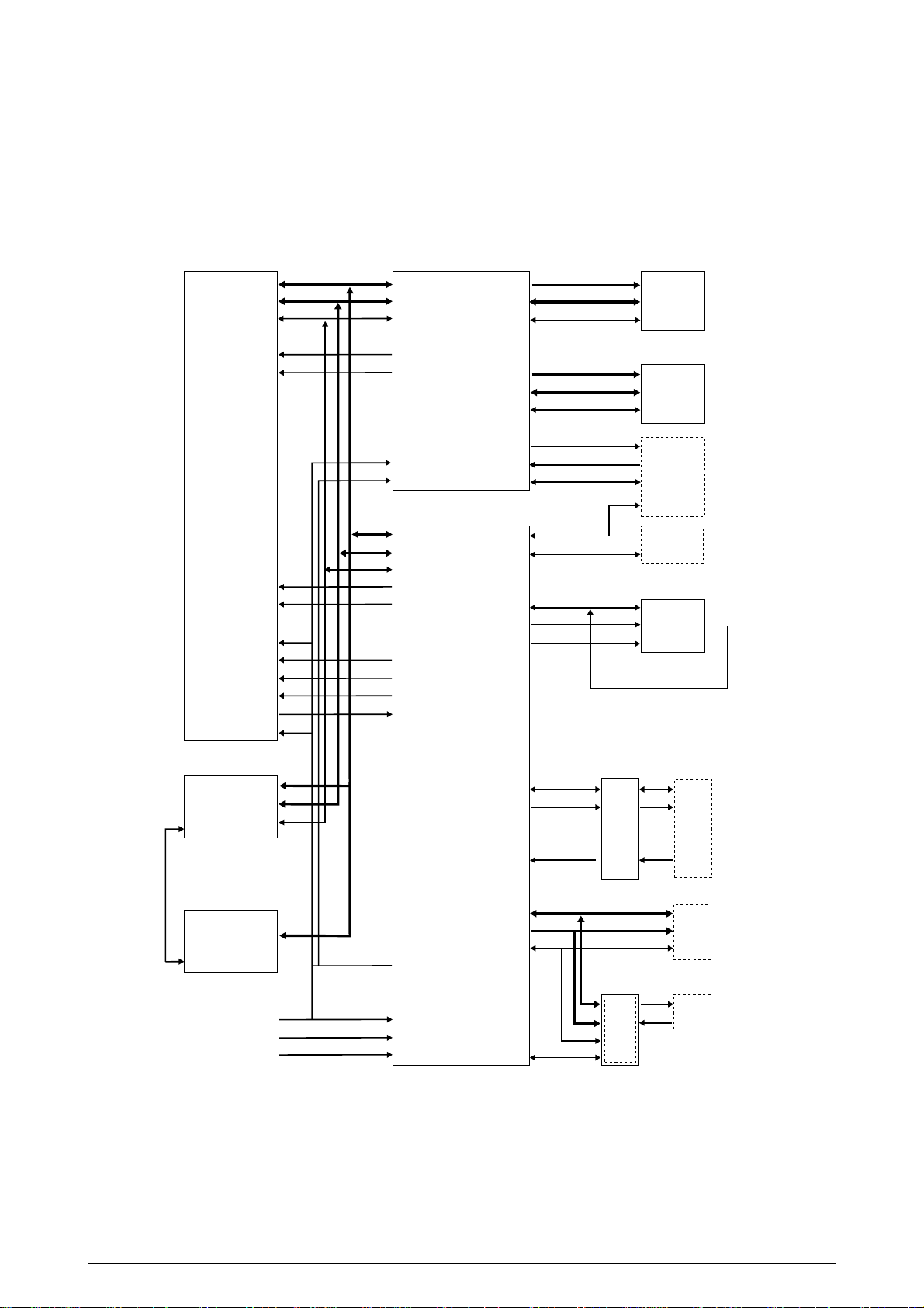
2.1 Main Control Board (PCE PCB)
The control board consists of a CPU (µPD30500S2-200) block, a memory control LSI block, an
interface control LSI block, a DRAM block, an EEPROM block, a mask ROM block, and an interface
block. Figure 2.2 shows the functional block diagram of the main control board (PCE PCB).
MPU Memory controller ROM, Flash Max 32M
SysAD
SysCmd
Control
NMI
INTO
µ
PD30500
S2-200
ExtReg
INT1
Reset
ColdReset
VCCOK
ModeIn
ModeClock
MasterClock
2nd cache controller
SysAD
SysCmd
Control
Control
64
9
5
1
1
1
1
64
9
5
1
1
1
1
1
1
SysAD
SysCmd
Control
uPD94704
NMI
S1-001-F6
INT
CLK
RST
Interface controller
SysAD
SysCmd
Control
ExtReq
INT
ColdReset
VCCOK
ModeIn
ModeClk
uPU66044
GN-014-LMU
A
D
Control
A
D
Control
WDATA
FSYNC
Control
PU I/F
OP I/F
EEPD
EEPCLK
EEPCS0
PD
PCO
PCI
22
64
11
11
64
25
8
4
4
9
4
1
1
1
8
5
4
D-RAM Max 144M
74LVC161284 Bi-Centro
WDATA
ESYNC
Control
Operator
panel
DI
CLK DO
CS
Engine
EE-PROM
2nd cache
Control
Reset circuit
SysAD
OSC
DIP SW
16
D
18
A
12
1
Reset
1
CLK
1
RSTIN
2
M
C
10
(TE6135 (6137), 16550, 53C80)
OKI HSP
Host I/F(Not installed)
Figure 2.2
41057601TH Rev.1 13/
Page 14

(1) CPU
The CPU is a 64-bit RISC architecture processor (provided by NEC). It inputs a frequency
of 50MHz and runs at 200MHz. It transfers data to and from memory at 50MHz.
(2) OTP ROM
The otp ROM block consists of four 16Mbit (1M x 16bits) chips and its total size is 8M bytes.
The chips are mounted on the PCE-PCB by means of IC sockets and store programs and
character fonts.
(3) DRAM
The DRAM block consists of eight 16Mbit (1M x 16bits) chips and its total size is 16M bytes.
The chips are mounted on the PCE-PCB and can be expanded up to 144M bytes by adding
the 32M byte SIMMs to the SIMM slots on the PCE-PCB.
(4) EEPROM
The EEPROM block consists of 16K-bit chips mounted on a board by means of IC sockets
and stores the following:
- Menu data
- Counter values
- Adjustment values
(5) Flash ROM
The Flash ROM block consists of four 4M bit (256K x 16bits) chips and its total size is 2M
bytes. The chips are mounted on the PCE-PCB and are used for storing fonts, macro and
demo pages.
(6) Memory control LSI
This block mainly consists of memory control, CPU control, compression and decompression, and video interface functions.
(7) Interface control LSI
This block mainly consists of PU interface control, operator panel interface control, EEPROM
control, parallel interface control, and HSP control functions.
(8) Host interface
This printer has the following interfaces to the host.
• Centronics bidirectional parallel interface
• HSP interface (Option)
The single effective interface or the automatic interface select mode can be selected using
the menu. If the busy state of the printer continues for a long time period, the buffer near-full
control releases the busy status at constant intervals even if the host side is busy so as not
to cause interface time-out at the host side.
(a) Centronics bidirectional parallel interface
This is an interface conforming to IEEE-1284 and provides either unidirectional and
bidirectional communications according to each of the following communication modes.
• Compatibility mode
Unidirectional communications from the host to the printer.
• Nibble mode
This mode transfers 4-bit wide data from the printer to the host. In this mode, each
bit of 1-byte data is transmits in the form of two nibbles using ERROR, BUSY, FAULT,
and SELECT signal leads. This mode can provide bidirectional operation in
combination with the compatibility mode.
41057601TH Rev.1 14/
Page 15
• ECP mode
This mode provides the asynchronous bidirectional interface and transmits and
receives 1-byte data using eight data signal leads under semi-duplex control by the
host.
When the power is turned on, the compatibility mode is automatically selected. The
change to another mode from the compatibility mode is made through negotiation.
(When the BI DIRECTION is set to ENABLE in the menu, this change can be performed.)
(For the electrical/physical characteristics of this interface, see APPENDIX B)
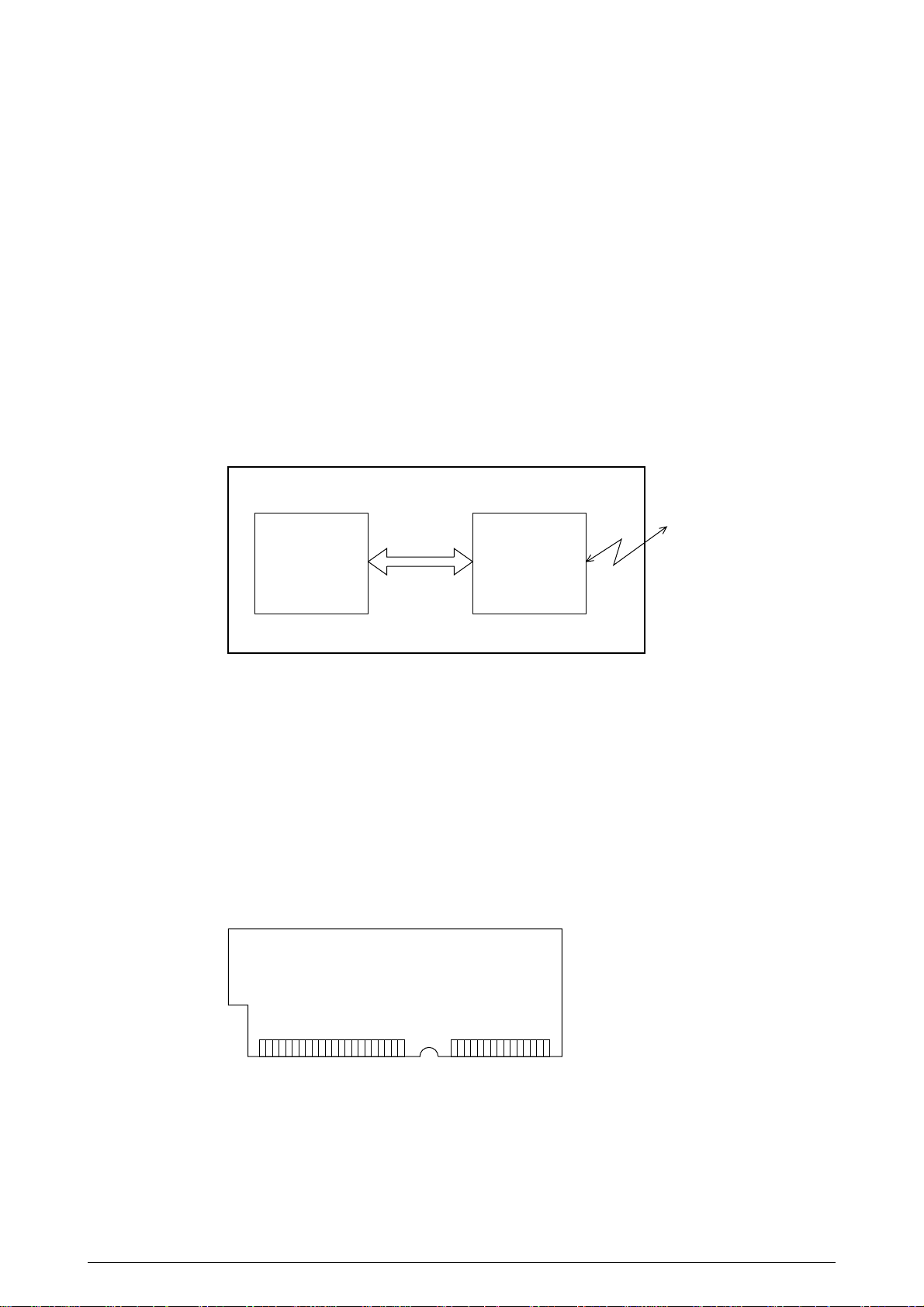
(b) HSP interface (Option)
This interface (slot) is an OKI unique universal interface that provides the platform to
connect various of boards (including those supplied by third venders) such as the LAN
connection expansion board and SCSI expansion board.
Any expansion boards compatible with this interface can be mounted on the Control
board in the piggyback board from without modifying the program at the printer side. The
conceptual diagram of the HSP interface is shown in Fig. 2-3.
Printer
Network, etc.
Control board
LAN
expansion board
HSP
interface
Figure 2.3
(For the electrical/physical characteristics of the HSP interface, see the HSP interface
technical manual.)
(9) 2nd Cache and 2nd Cache Controller
This printer has 2nd Cache unit which type is Write Through Cache and size is 512 KByte.
Thereare any difference between the instruction and data.
All of the CPU read/ write accesses are cached to same 2nd Cache memory.
(10) RAM module
• Pin layout
1363772
• Basic specificaton
- Type: 72 pins SIMM (32 bits buss width)
- Access time: 60ns, 70ns, 80ns
- Capacity: 4, 8, 16 or 32MB
- Parity: None
41057601TH Rev.1 15/
Page 16
2.2 Engine Control Board (PX4 PCB)
NM93C66N-NW
CPU BUS
VIDEO I/F
(Heater temperatures and envirnment humidity and temperature)
EEPROM
VIDEO MEM
HM658512
OSC 28MHz
RESET
ANALOG INPUT
CPU
MSM65524
(containing AD converter)
INT
LSI
MB87D
113PFV
MT DRIVER
MTD2005F
MT DRIVER
MTD2005F
MT DRIVER
MTD2005F
ROM
27512
Y HEAD I/F (3.3V)
M HEAD I/F (3.3V)
C HEAD I/F (3.3V)
B HEAD I/F (3.3V)
PULSE MOTOR x 8
HIGH-VOLTAGE POWER SUPPLY
SERIAL INTERFACE (2 channels)
GENERAL INPUT PORT
GENERAL OUTPUT PORT
Figure 2.4
The engine control block (PU) is controlled by the engine control board (PX4 PCB) which consists
of a CPU (MSM65524), general purpose LSI chips, EPROM, EEPROM, pulse motor drivers, and
video memory. (See Figure 2.4.)
(1) CPU
This is an 8-bit CPU (OKI MSM65524) containing the AD converter and controls the whole
system.
(2) General-purpose LSI
This LSI (MB87D113PFV) is provided in the printer engine control block and has controllerengine video interface, LED interface, motor control, sensor input, video memory control,
main scanning color correction, skew correction, high-voltage power control, and OST-EX2
functions.
41057601TH Rev.1 16/
Page 17
(3) EPROM
This EPROM (27C512-150) has a storage capacity of 512K bits and stores programs for the
PU block.
(4) EEPROM
This EEPROM (NM93C66N-NW) having a storage capacity of 4K bits is mounted on the
board by means of IC socket and stores adjustment values etc.
(5) Pulse motor drivers
These drivers (MTD2005F) drive eight pulse motors for moving up and down the EP and
transferring medium.
(6) Video memory
This SRAM receives print data through video interface and stores it.
2.3 Power/Units
The power supply unit comprises of the low voltage power supply unit which consists of an AC filter
circuit, low voltage power supply circuit and heater driver circuit, and the high voltage power supply
unit.
(1) Low voltage power supply unit
This circuit generates the following voltages.
Output voltage Use
+3.3 V CU Unit CPU, LED HEAD
+5 V Logic circuit supply voltage
+32 V Motor and fan drive voltage and source voltage for high-voltage supply, discharge lamp
+12 V HSP, OP Amp, high voltage power supply
–12 V HSP
(2) High voltage power supply unit
This circuit generates the following voltages necessary for electro-photographic processing
from +32 V in accordance with the control sequence from the control board. When cover open
state is detected, +32 V supply is automatically interrupted to stop the supply of all the highvoltage outputs.
Output Voltage Use Remarks
CH -1.35 KV ± 50V Voltage applied to charging roller
DB Normal paper Voltage applied to developing roller
Y. M. C : -250V/+300V, -232V/+300V(First paper. Y only)
K : -275V/+300V
Transparency
Y. M. C. : -200V/+300V, K. : -250V/+300V
SB Y. M. C.K : -650V/0V Voltage applied to toner supply roller
TR 0 to 4 KV Voltage applied to transfer roller Variable
FIX 0 to 2.5 KV Voltage applied to transfer roller Variable
41057601TH Rev.1 17/
Page 18
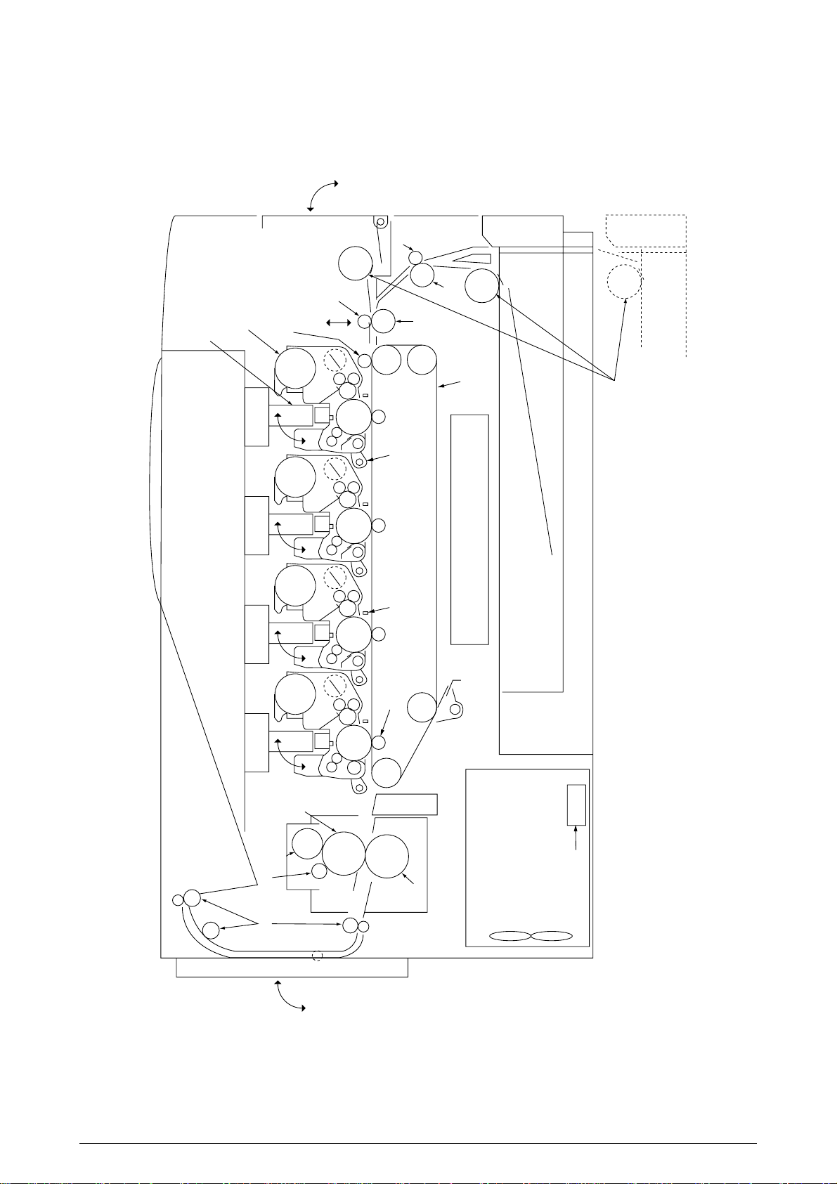
2.4 Mechanical Processes
Paper
ejection
roller
Paper
ejection
(Face down)
Power
supply
Charging
roller
Cleaning
blade
Paper
path
selection
Heat roller
Ejection
roller
Fixing
Backup roller
Control signal
LED head
Developing
roller
Power
supply
Toner
cartridge
Transfer
roller
Paper
resist
Resist
roller 1
Paper
feed
Hopping
roller
Power
supply
Resist
roller 2
Paper ejection Fixing Cleaning Transferring
Paper pickup
Paper conveying Paper hopping
Movement of
paper
Rotation of
OPC drum
Transferring
Charging
Exposure
Developing
Cleaning
Paper ejection
sensor
Form feed sensor 1
Paper
ejection
(Face up)
Form feed sensor 2
Front
feeder
Paper
cassette
Paper
resist
Paper
pickup
(FF, 1ST, 2ND)
Write sensor
x 4
Y M C K
Figure 2.5 shows the mechanical processes of OKICOLOR 8/ OKIPAGE 8c Plus.
41057601TH Rev.1 18/
Figure 2.5
Page 19

2.4.1 Electrophotographic processing mechanism
(1) Electrophotographic processes
Each process of the electrophotographic processing mechanism is outlined below.
1 Paper pickup
This process causes the roller to give a DC voltage to the paper to have a negative charge.
With this negative charge, the paper is electrostatically attracted to the roller.
2 Charging
This process gives a DC voltage to the CH roller so that the OPC drum may have a uniform
negative charge on its surface.
3 Exposure
This process causes the LED head to apply light beams according to image signals to the
negatively-charged surface of the OPC drum. The negative charge on the illuminated
surface of the OPC drum is reduced according to magnitudes of the light beams.
Thus, a latent image is formed on the surface of the OPC drum according to the resulting
surface potentials.
4 Developing and recovery of excessive toner
This process applies negatively-charged toner to the surface of the OPC drum. The toner
is electrostatically attracted to the latent image to form a visible image on the surface of
the OPC drum. Simultaneously, this process electrostatically transfers excessive toner
from the OPC drum to the developing roller.
5 Transferring
This process fits paper to the surface of the OPC drum, applies positive charge (opposite
to the charge of the toner) to the back side of the paper from the transfer roller. The toner
image is transferred to the paper.
6 Cleaning
Cleaning blade scrapes off the remaining toner from the OPC drum which has been used
to transfer.
7 Fixing
This process fixes the toner image on the paper by pressing and fusing the image.
41057601TH Rev.1 19/
Page 20
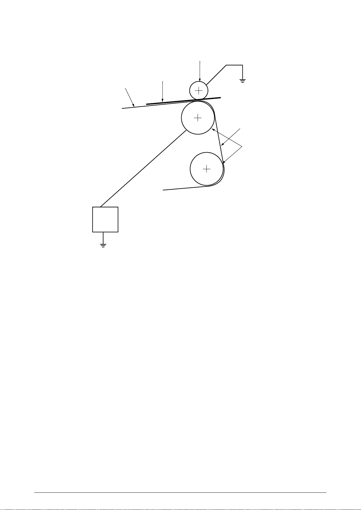
(2) Paper pickup
Pickup roller
Paper (medium)
Conveying belt
A
Conveying belt
Driven roller
B
Power
supply
A DC voltage (0V to 2KV) is applied to the driven roller A to positive charge the lower surface
of the paper. The negatively-charged paper is electrostatically attracted to the pickup roller.
With this, the paper is in close-contact with the conveying Belt and conveyed steadily.
41057601TH Rev.1 20/
Page 21
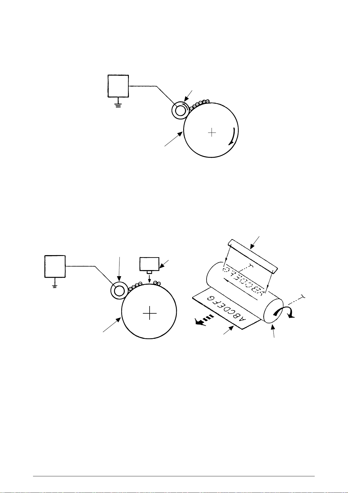
(3) Charging
This process applies a DC voltage to the charging roller in contact with the surface of the OPC
drum.
Power
supply
unit
OPC drum
Charging roller
(4) Exposure
The light beams from the LED head are applied to the surface of the OPC drum which is
charged negatively. The negative charge on the illuminated surface of the OPC drum is
reduced according to magnitudes of the light beams and a latent image is formed on the
surface of the OPC drum according to the resulting surface potentials.
Power
supply
unit
Charging roller
OPC drum
LED head
Paper
LED head
OPC drum
41057601TH Rev.1 21/
Page 22
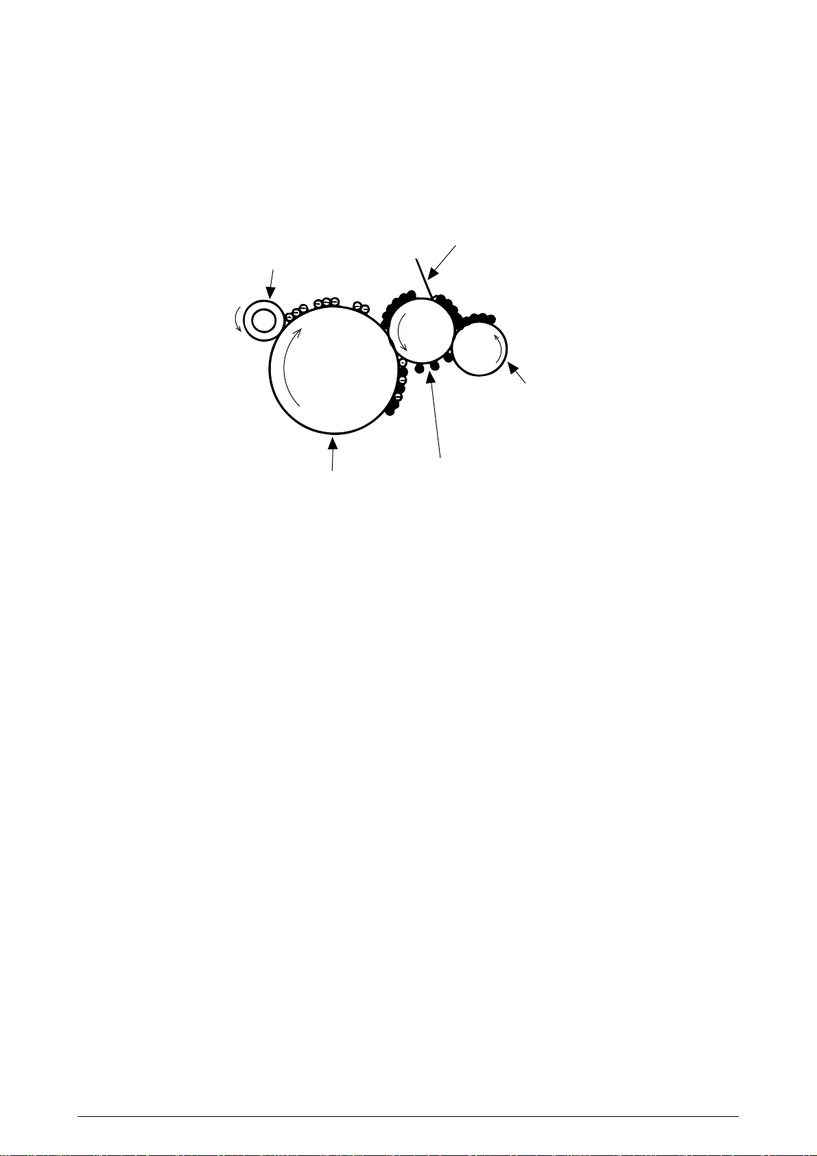
(5) Developing
This process applies toner to the latent image on the surface of the drum to convey it into a
toner image. Developing is carried out on the surface of the OPC drum at which the OPC drum
is in contact with the developing roller.
1 The sponge roller transfers toner to the developing roller. The toner is charged
negatively.
Developing toner blade
Charging roller
Sponge roller
Developing roller
OPC drum
2 The toner blade scrapes away excessive toner on the developing roller to form a thin
film of toner on the surface of the developing roller.
3 The toner is attracted to the latent image on the surface of the OPC drum at which
the OPC drum is in contact with the developing roller. The latent image on the
surface of the OPC drum is made visible with the toner.
41057601TH Rev.1 22/
Page 23
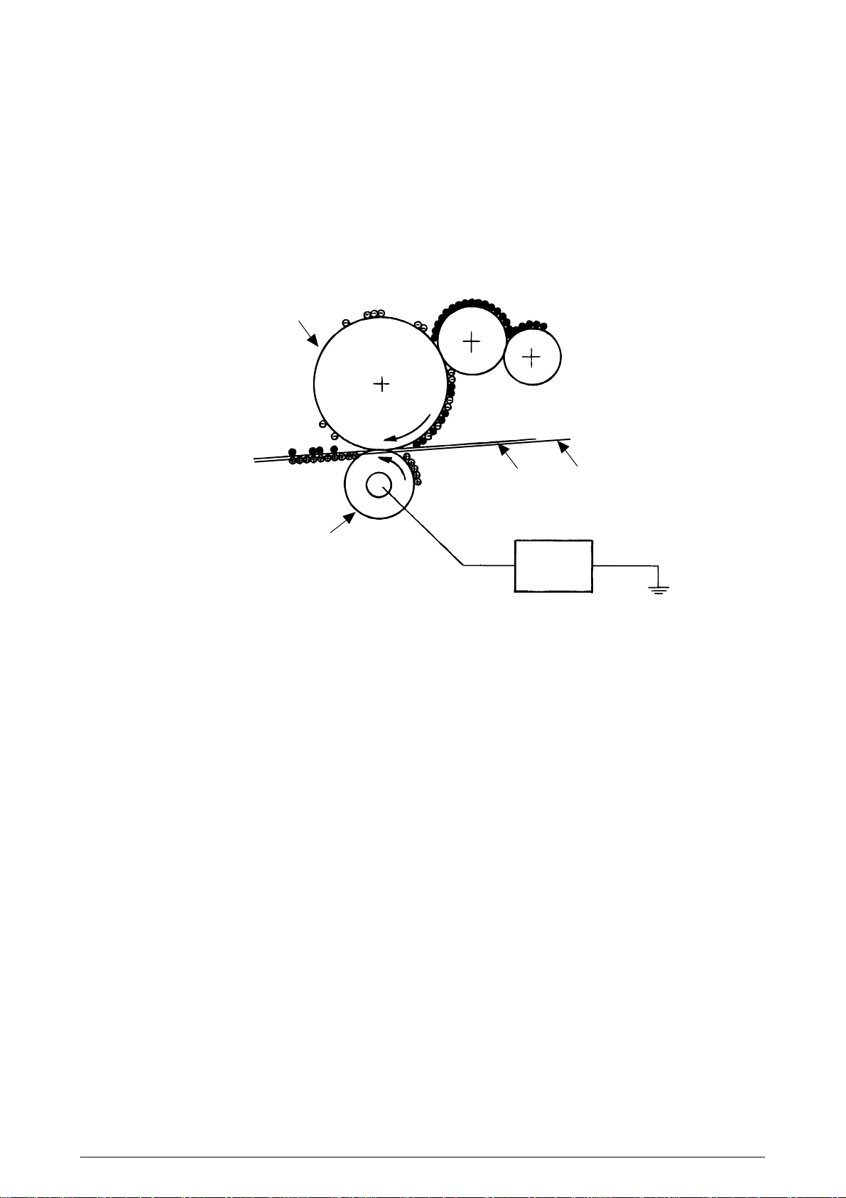
(6) Transferring
The transfer roller made of conductive sponge presses the paper
against the surface of the OPC drum so that the paper may be close contact with the surface
of the OPC drum.
This process fits the paper to the surface of the OPC drum by the transfer roller and applies
positive charge (opposite to the charge of the toner) from under the paper.
When a positive high voltage is applied to the transfer roller from the power supply, the
positive charge induced on the transfer roller jumps to the upper surface of the paper at which
the transfer roller touches the paper and attracts the negatively-charged toner from the
surface of the OPC drum onto the surface of the paper.
OPC drum
Conveying belt
Paper
Transfer roller
Power
supply unit
41057601TH Rev.1 23/
Page 24
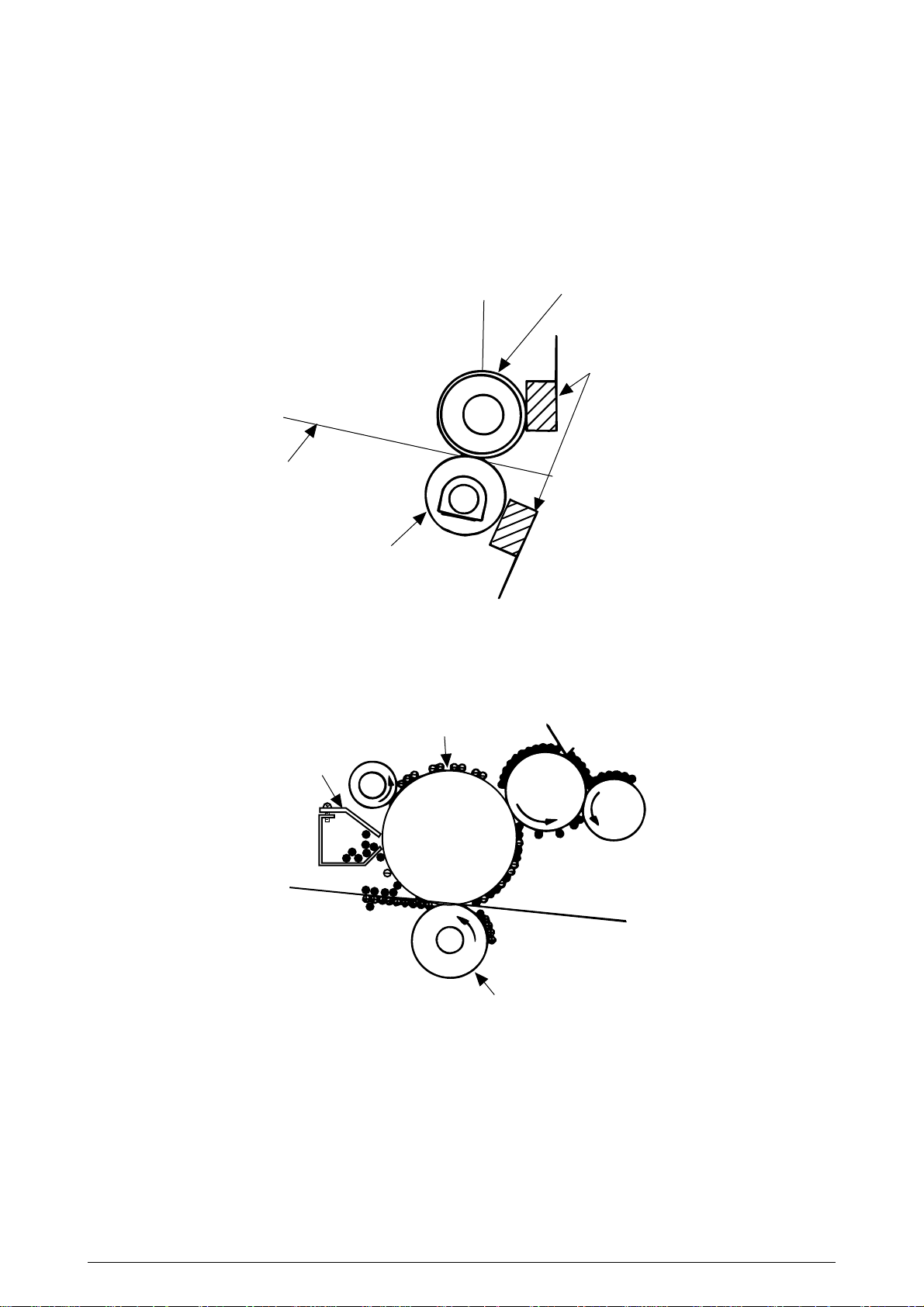
(7) Fixing The toner image just transferred to the paper is fused and fixed to the paper while
the paper is passing through the gap between the heat roller and the backup roller.
The teflon-coated surface of the heat roller is heated up by the 800-watt heater (or a
halogen lamp) provided in the heat roller. The temperature of the heat roller surface is
controlled by a thermistor in contact with the surface of the heat roller. A thermostat is
provided for safety. When the heat roller temperature goes higher than the preset
temperature, the thermostat opens and shut off power to the heater in the heat roller.
The backup roller is evenly pushed against the heat roller by two end springs.
Heater
Paper
Backup roller
Heat roller
Thermistor
(8) Cleaning
The toner which remains on the OPC Drum without being fused is scraped by a cleaning blade
and discarded in the waste toner tank.
OPC drum
Cleaning blade
Transfer roller
41057601TH Rev.1 24/
Page 25
2.4.2 Paper running process
face down stacker
oil roller
fuser
low-voltage power supply
AC switch
transfer roller
x
4 light rejector
x
4
transfer belt unit
ID unit up / down actuater
belt cleaning
high voltage power supply
pick up roller
pinch roller up / down
transfer belt
1st tray
2nd tray
front feeder
KCMY
I/D unit
LED Head
pinch roller 2
pinch roller 1
regist
roller 2
regist
roller 1
hopping roller
backup roller
Eject roller
oil cleaning roller
heat roller
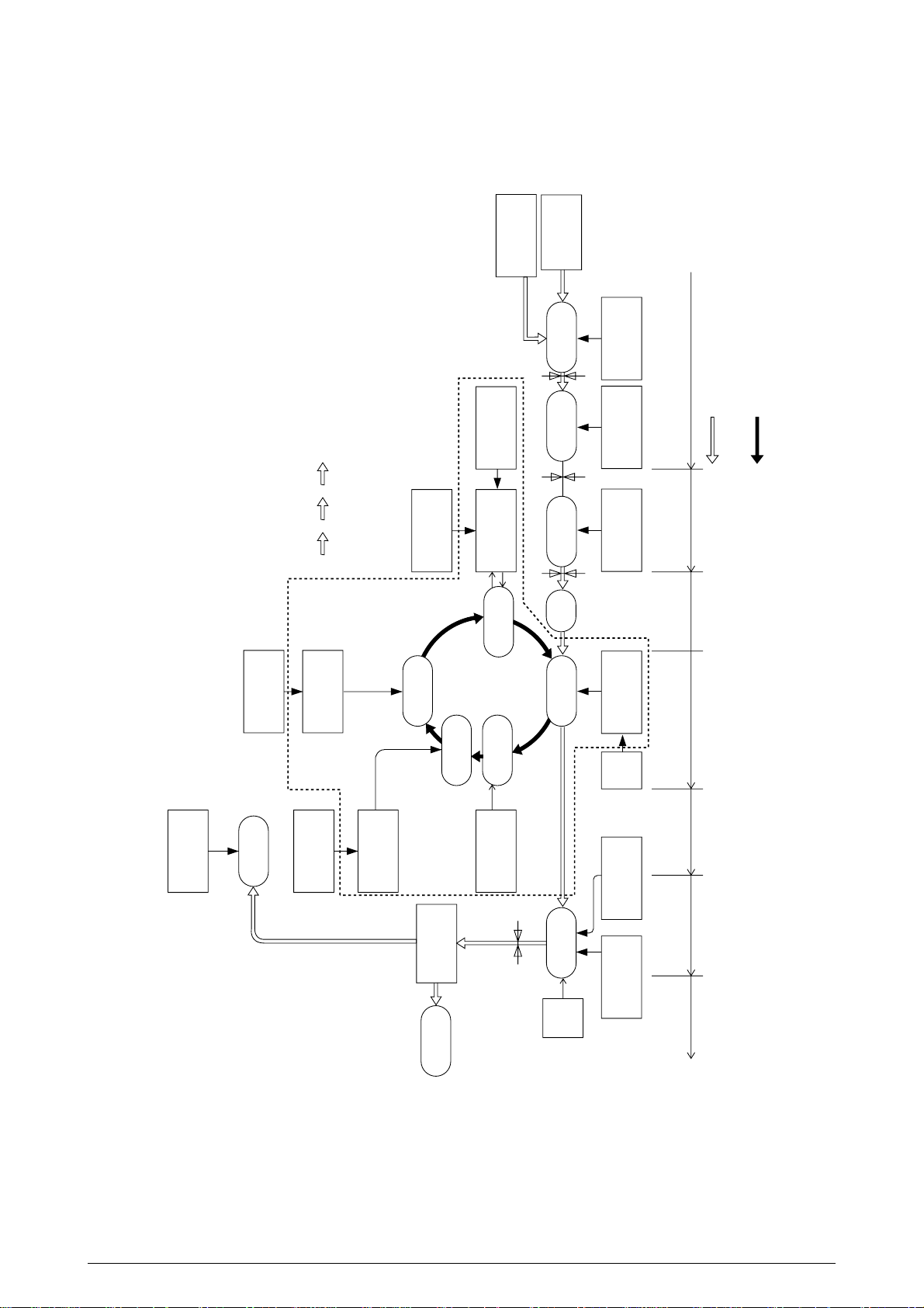
Figure 2.6 shows how paper moves in the OKICOLOR 8/ OKIPAGE 8c Plus.
Figure 2.6 Paper Route
41057601TH Rev.1 25/
Page 26
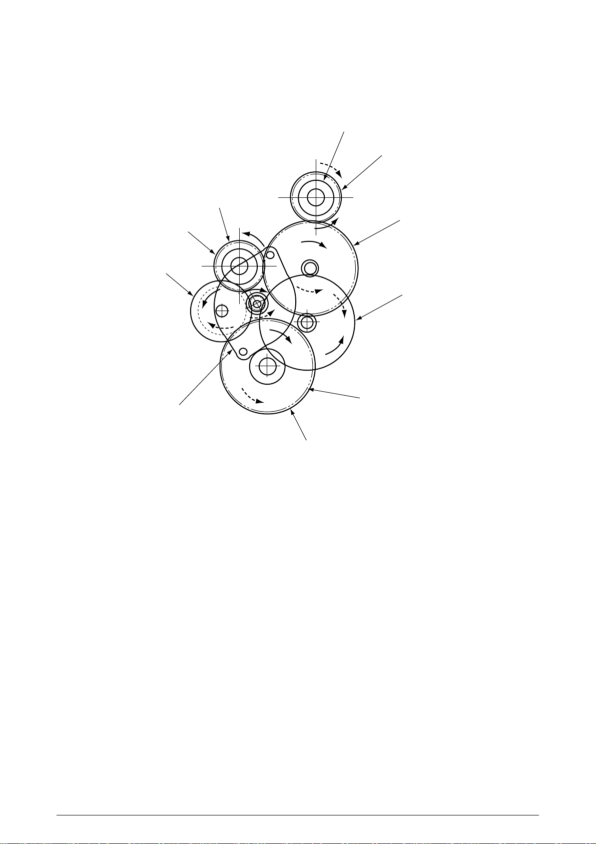
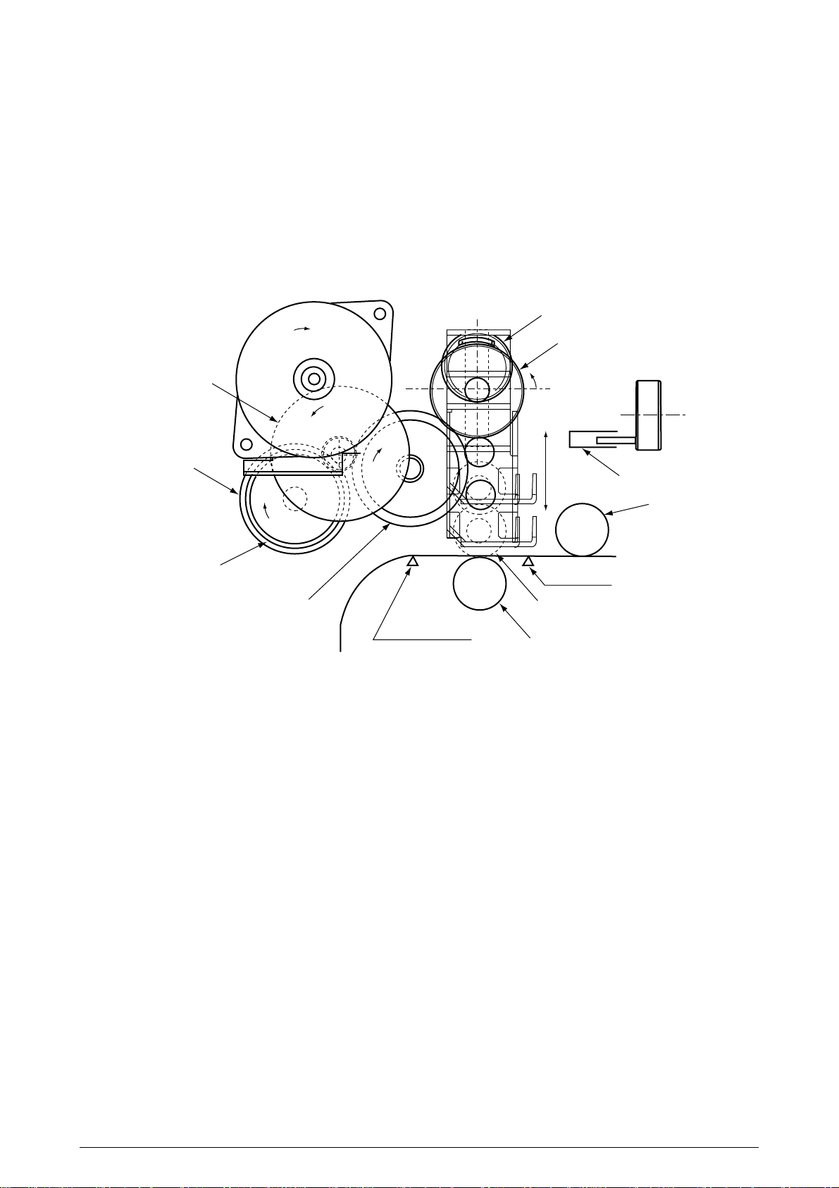
(1) Paper hopping and transfer and up/down movement of pinch roller 2
Paper is hopped and delivered by the mechanism shown below. This mechanism is driven
by a single pulse motor.
Resist roller 2
One-way gear C
Resist roller 1
Idle gear C
One-way gear B
Idle gear A
a
b
Idle gear B
First hopping roller
Pulse motor
One-way gear A
The pulse motor turns in the arrow direction (a) and drives the hopping roller in the direction of
“b.” The hopping roller drives the resist roller.
Each of the one-way clutch gears A, B, and C has a one-way clutch to prevent the rollers from
rotating reversely.
41057601TH Rev.1 26/
Page 27
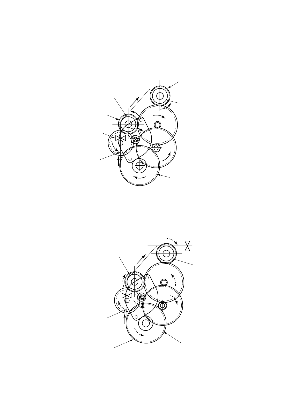
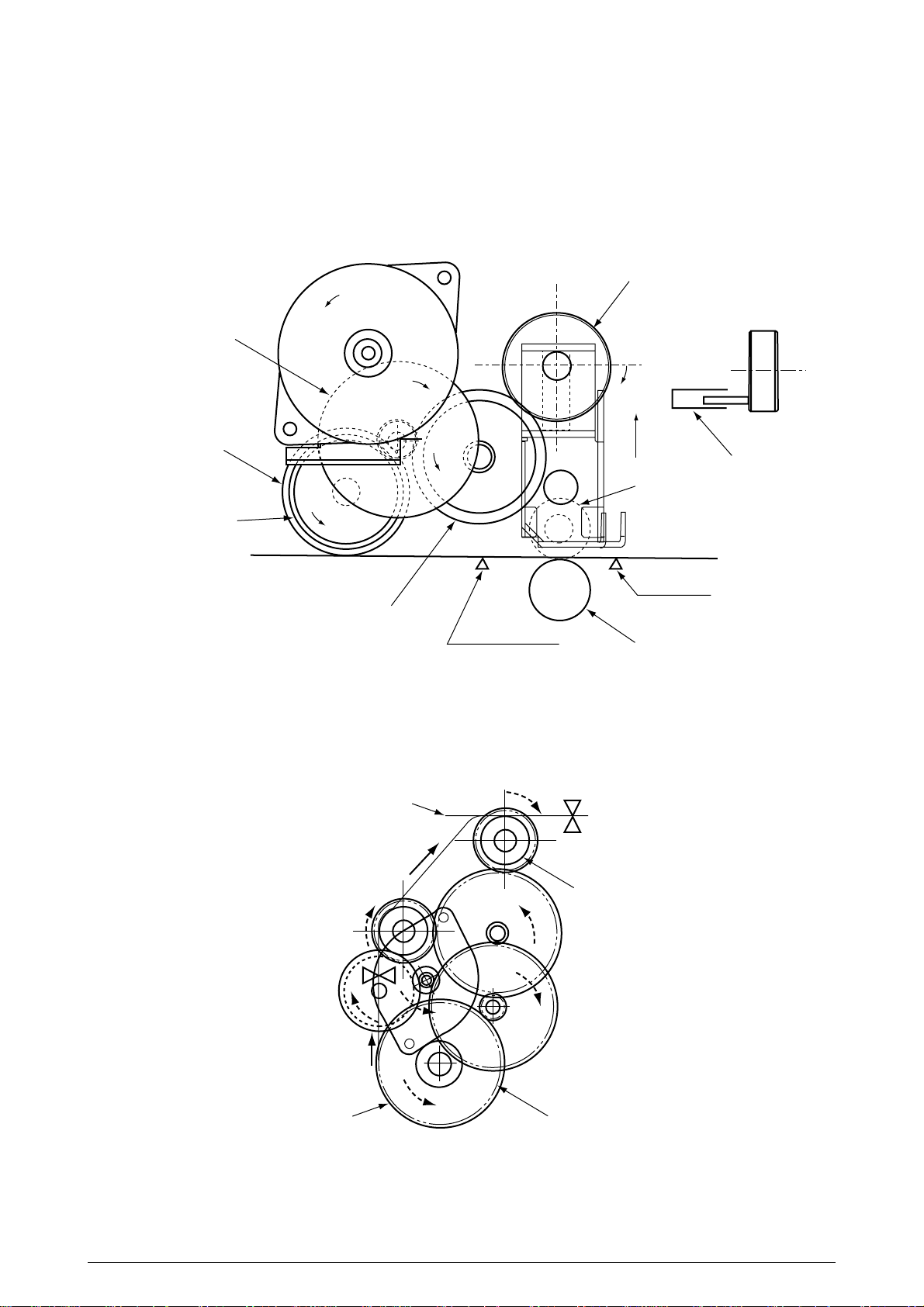
(a) Hopping
1 The pulse motor turns in the arrow direction of “a” (counterclockwise) and drives the
hopping roller to move the paper until the Entrance sensor turns on. Although the oneway gears B and C are also driven, the resist roller 2 does not turn because the
reverse rotations of the one-way clutch gears are not transmitted to the resist roller.
2 After the Entrance sensor turns on, the hopping roller keeps on feeding the paper until
it hit the resist roller 1. (This operation corrects any paper skew.)
One-way gear C
Resist roller 1
Resist roller 2
One-way gear B
Entrance sensor
Paper
a
First hopping roller
(b) Conveying
1 After paper hopping is completed, the pulse motor turns right (in the direction of “b”)
to drive the resist rollers 1 and 2. The resist rollers feed the paper until the Form
sensor turns on.
Although the one-way gear A is also driven, the hopping roller does not turn because
of the one-way clutch.
2 The paper is further fed in synchronism with the print data.
Form sensor
Resist roller 1
Resist roller 2
b
Paper
First hopping roller
One-way gear A
41057601TH Rev.1 27/
Page 28
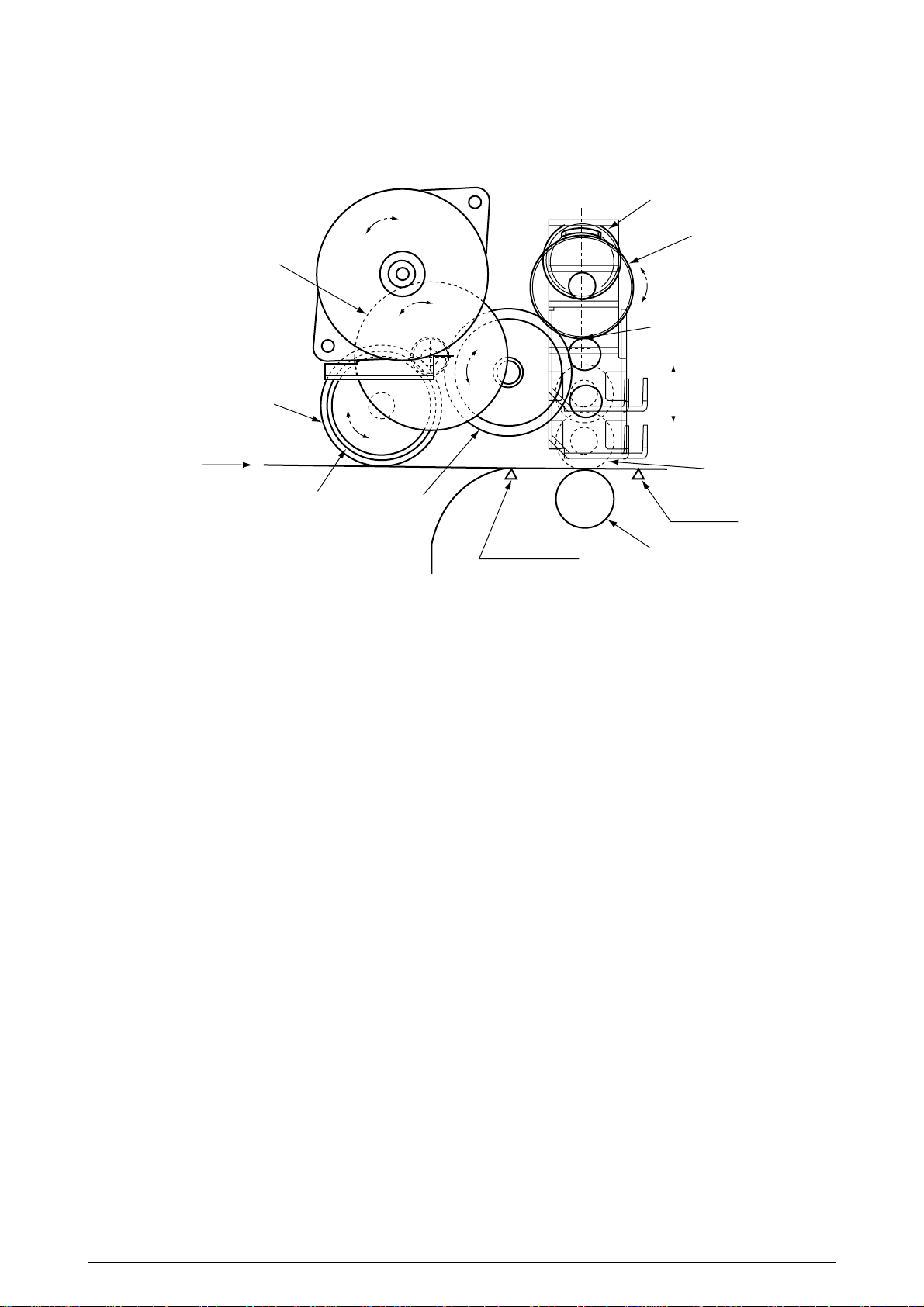
(2) The hopping operation of the front feeder and the up/down operation of the pinch roller 2 are
performed by a single pulse motor, as shown below.
Cam
b
a
Idle gear A
One-way clutch gear B
Sensor position
From front
Hopping roller
One-way clutch gear A Idle gear B
Entrance sensor
Up/down
Pinch roller
Form sensor
Resist roller 2
When the pulse motor of the front feeder turns right (in the direction of “A”), the front hopping
roller turns left (in the direction of “b”) to drive the cam. This cam moves up and down
the pinch roller 2. The one-way clutch gears are made to turn only in a preset direction by
means of the one-way clutches.
41057601TH Rev.1 28/
Page 29
(a) First and second hopping rollers
1 When the front edge of the paper passes by the pickup roller, the pulse motor of the
front feeder turns left (in the direction of “b” to drive the cam. The cam moves up the
pinch roller 2. Although the one-way clutch gear A is also rotating, the hopping roller
of the front feeder does not rotate by means of the one-way clutch.
2 When the rear edge of the paper passes by the Entrance sensor 2, the pulse motor
of the front feeder turns left (in the direction of “b”) to drive the cam. The cam moves
down the pinch roller 2 until it is sensed by the sensor. Although the one-way clutch
gear A is also rotating, the hopping roller of the front feeder does not rotate by means
of the one-way clutch.
Cam
b
One-way clutch gear B
Idle gear A
Hopping roller
One-way clutch gear A
Idle gear B
b
b
Paper from the tray
b
Entrance sensor 2
b
Up
Cam
Sensor
Pickup roller
Form sensor
Pinch roller 2
Resist roller 2
41057601TH Rev.1 29/
Page 30
(b) Front feeder hopping
1 The pulse motor of the front feeder turns right (in the direction of “a” to drive the
Idle gear A
Hopping roller
One-way clutch gear A
Paper from front feeder
hopping roller. The paper is fed until the Entrance sensor 2 turns on. Although the
one-way clutch gear B is also rotating, the pinch roller 2 does not drive the up/down
cam by means of the one-way clutch.
After turning on the Entrance sensor, the paper is further fed until it hits the resist roller
2. (This operation corrects any paper skew.)
One-way clutch gear B
a
b
Cam
Sensor
Pickup roller 2
Form sensor
Idle gear B
Entrance sensor 2
Resist roller 2
(c) Conveying
1 After paper hopping is completed, the pulse motor turns right (in the direction of “b”)
to drive the resist rollers 1 and 2. The resist rollers feed the paper until the Form
sensor turns on.
2 Although the one-way gear A is also driven, the first hopping roller does not turn
because of the one-way clutch.
Paper
b
Form sensor
Resist roller 2
One-way gear A First hopping roller
41057601TH Rev.1 30/
Page 31

(2) Up/down movement of the I/D unit and rotation of the EP drum
The up/down movement of the I/D unit and the rotation of the EP
drum are performed by a mechanism shown below. (See Figure 2.6-a) This mechanism is
driven by a single pulse motor.
When the pulse motor turns left (CCW), the up/down gear turns left (in the direction of “a”) and
the up/down lever (see Figure 2.6-b) moves up (in the direction of “ ”). The up/down lever
pushes up the up/down actuator of the I/O unit. The I/D unit moves up as shown in Figure
2.6-b. The EP drum rotates freely.
a
Up/down gear
Z53/44
b
Z25/75
CCW
Pulse motor
CW
Z67/43/24
EP drum gear
CCW
Figure 2.6-a
When the pulse motor (see Figure 2.6-a) turns right (CW), the EP drum gear turns left (CCW)
and the up/down gear (one-way gear) is released. The weight of the I/D unit is applied to the
up/down lever via the up/down actuator of the I/O unit. The free up/down gear turns right (in
the direction “b” in Figure 2.6-a) and the I/D unit goes down until the up/down actuator of the
I/D unit is stopped by the up/down lever. (See Figure 2.6-c.) During this, the image is
transferred onto the running paper.
41057601TH Rev.1 31/
Page 32

I/D unit up/down actuator
Up/down lever
Up/down lever
I/D unit
Figure 2.6-b
I/D unit
Figure 2.6-c
41057601TH Rev.1 32/
Page 33

(3) Lubrication and cleaning of fixing, ejecting, and heat rollers
a
a
Ejection roller
Oil cleaning roller
a
a
Face-down stacker
Oil roller
a
Hear roller
a
a
The fixing roller, the ejecting
roller, and the heat roller are lubricated and cleaned by a single
pulse motor.
When the heat roller pulse motor
turns right (in the direction of “a”),
the heat roller and the backup
roller turn left (in the direction of
“a”) to fix a toner image onto the
paper.
At the same time, three ejection
rollers turn right (in the direction
of “a”) to eject the paper. The oil
roller and the oil cleaning roller
turn left (in the direction of “a”) to
supply oil to the surface of the
heat roller and clean the surface.
Backup roller
Heat motor
Fixer
41057601TH Rev.1 33/
Page 34

2.5 Sensors
2.5.1 Paper related sensors
Ejection roller
Heat roller
Exit sensor
Backup roller
Sensor
FF sensor 1/2
(Entrance sensor 1/2)
Form width sensor
Write sensor
Ejection sensor
K drum C drumM drumY drum
Driving roller
Driven rollers
Belt cleaning blade
Function
Detects the front edge of an incoming paper and determines
timing to change from hopping to conveying.
Senses the width of the paper sheet.
Detects the front edge of the conveyed paper sheet and determines the
length of the paper sheet from elapsed time before the front edge of the
paper reaches the sensor.
Detects the front and rear edges of a paper sheet and determines
whether the paper is ejected.
Conveying belt
Write sensor
Pickup roller
Pinch roller 2
Resist roller 2
FF sensor 2
First hopping roller
Second hopping roller
Sensor status
ON: Front edge detected
OFF: Front edge not detected
ON: A4 size or bigger
OFF: Smaller than A4 size
ON: Form present
OFF: Form absent
ON: Form present
OFF: Form ejected
FF hopping roller
Form width sensor
Pinch roller 1
Resist roller 1
FF sensor 1
Auxiliary rollers
41057601TH Rev.1 34/
Page 35

2.5.2 Other sensors
1 Form end sensor
This sensor checks whether the paper cassette is empty.
2 FF form end sensor
This sensor checks whether the front feeder has paper.
3 FF home switch
This microswitch checks whether the front feeder stage is in the up or down position.
4 EP up/down sensor (one for each color Y, M, C, K)
This sensor checks whether the I/D unit is in the up or down position.
5 Waste toner sensor
This sensor judges whether the waste toner cartridge is full by measuring a time period at
which the sensor lever turns on periodically. When the time period falls under a preset
value, the system judges that the waste toner cartridge is full and displays the “waste
toner full” message.
6 Resist up/down sensor
This sensor detects the up or down position of the resist roller 2.
7 Temperature sensor
Refer to 2.8 (Transfer Control according to Environmental Changes).
8 Humidity sensor
Refer to 2.8 (Transfer Control according to Environmental Changes).
41057601TH Rev.1 35/
Page 36

2.6 Correction of Color Deviation
OKIPAGE 8c is equipped with an array of I/D units which cannot be from generation of color
deviations. This mechanically caused color deviation is corrected electronically as shown
below.
(1) Color deviations to be corrected
1 Color deviation in the X axis (Positional error of the LED head)
2 Diagonal color deviation (Positional error of the LED head)
3 Color deviation in the Y axis (Positional errors of the I/D units and light receivers)
(2) Method of correction Print out the preset color chart, compare the printed color chart by
the original color chart, and enter the amount of color deviation of each color from the
operator panel or from the host computer. OKIPAGE 8c calculates correction values from
the entered values and changes the write timing of each color (cyan, magenta, and
yellow) relative to black.
2.7 Transfer Control according to Environmental Changes (Room Temperatures and
Relative Humidities)
OKIPAGE 8c measures the room temperature and humidity by the room temperature sensor
and the room humidity sensor, calculates an optimum transfer voltage according to the obtained environmental conditions and realtime-controls printing with the optimum transfer
voltage.
41057601TH Rev.1 36/
Page 37

2.8 Form Jam Detection
OKICOLOR 8/ OKIPAGE 8c Plus checks for a paper jam when the page printer is powered on
and during printing. When finding a paper jam, OKICOLOR 8/ OKIPAGE 8c Plus immediately
stops the printing process. To recover the printer, open the cover, find and remove the
jammed paper, then close the cover.
Error
Form feed jam
Convey jam
Ejection jam
Form size error
Three hopping operations are made, but the Form Feed sensor (Entrance) does not turn on a preset
time after the Form Feed sensor 1 turns on.
The ejection sensor does not turn on a preset time period after the Write sensor detects the front end
of paper.
The ejection sensor detected the front edge of the paper but does not detect the rear edge of the paper
for a preset time period.
The form size obtained by measuring the time period before the rear edge of the paper passes by the
Form Feed sensor 2 after the front edge of the paper passed the Write sensor is longer by 45mm than
the specified form length.
2.9 Cover Opening
When the upper, side, or front cover of OKICOLOR 8/ OKIPAGE 8c Plus is opened, the Cover
Open microswitch turns off, a voltage of 32V to the high-voltage power supply is shut off, and
all high-voltage outputs are shut off. At the same time, the CPU receives a signal (CVOPN)
indicating the status of the microswitch and performs the cover open process.
PX4-PCB
CPU
65524
+32V
Conditions
Upper cover
microswitch
Side cover
microswitch
Front cover
microswitch
P4.7
12
COVOPN (2P)
High-voltage power supply board
HVOLT (16P)
detect
circuit
High-voltage power supply unit
41057601TH Rev.1 37/
Page 38

2.10 Toner Low Detection
• Composition
The device consists of the stirring gear which rotates at a constant rate, the stirring bar and
the magnet on the stirring bar. The stirring bar rotates through the engagement of concave
in the stirring gear.
Magnet
Stirring Bar Stirring Gear
• Operation
Toner Low is detected by monitoring the time interval of the encounter of the magnet set on
the sensor lever and the magnet on the stirring bar.
Stirring Gear Section
Operation during toner full state
• The stirring bar rotates due to the interlocking
with the stirring gear.
• Even when the magnet on the stirring bar
reaches the maximum height, since the other
side is being dipped in the toner, the stirring bar
is pushed by the stirring gear.
Stirring Bar
Toner Sensor
Concave
Sensor Lever
Stirring Bar
Operation during toner low state
• When the stirring bar reaches the maximum
height, since there is no resistance provided by
the toner on the other side, it falls to the minimum height due to its own weight. Because of
this, the time interval during which it is in encounter with the magnet of the sensor lever
becomes long. By monitoring this time interval,
toner low can be detected.
41057601TH Rev.1 38/
Sensor Lever
Page 39

TONER FULL state
TNRSNS
t1
1.965 SEC.
t1 < 0.74 SEC (Y)
t1 < 1.165 SEC (M, C, K)
TONER LOW state
TNRSNS
t1
1.965 SEC.
t1 > 0.74 SEC (Y)
t1 > 1.165 SEC (M, C, K)
• When the toner low state is detected for 2 times consecutively, Toner Low is established.
• When the toner full state is detected for 2 times consecutively, Toner Low is cancelled.
• When there is no change with the toner sensor for 2 cycles (1.965 sec. x 2) or more, then the
Toner Sensor Alarm is activated.
• The toner sensor is not monitored while the drum motor is in halt.
2.11 Page Size Detection
The four tab pieces are driven according to the setting position of the paper guide through the cam
interlocked with the paper guide of the paper cassette.
When the paper cassette is inserted into the printer, the state of the tab pieces is detected by the
microswitch to recognize the paper size.
State of Microswitches Paper size
SW1 SW2 SW3 SW4
0111Letter
0101Executive
0011A4
1110Legal 14
1011Legal 13
1101B5
1100A5
1001A6
41057601TH Rev.1 39/
Page 40

2.12 Power-on Processing
2.12.1 Self-diagnostic test
(1) Initial test
The following checks are automatically performed when the OKICOLOR 8 / OKIPAGE 8c
Plus page printer is powered on:
(a) ROM check
(b) RAM check
(c) EEPROM check
(d) Flash ROM check
(2) ROM check
(a) Checks ROM by comparing the sum of bits in the received data unit by the number of bits
in the transferred data unit.
(3) RAM check
(a) Checks RAM by writing a preset data pattern in RAM, reading the contents of RAM, and
comparing the data read from RAM by the data written in RAM. (Write-read test)
(b) Checks optional RAM if it is installed.
(c) Checks resident RAM by exclusively ORing high and low addresses (to prepare 16-bit
data units), writing a preset 16-bit data pattern in RAM, reading the contents of RAM, and
comparing the data read from RAM by the data written in RAM. Checks optional RAM
by writing and reading 32-bit fixed patterns (“5555h” and “aaaah”) in optional RAM.
(4) EEPROM check
(a) Checks ID numbers stored in the fixed addresses of EEPROM.
(b) Checks the content of the menu area by control firmware and the engine area by engine
firmware.
(5) Flash ROM check
Checks Flash ROM by writing a present data pattern in Flash ROM, reading the contents
ofFlash ROM, and comparing the data read from Flash ROM by the data written in Flash
ROM. (Write-read test).
(6) Option unit check
Checks whether the optional units (such as the second tray, PS SIMM, and so on) have been
installed before entering the operation mode.
41057601TH Rev.1 40/
Page 41

3. PARTS REPLACEMENT
The section explains the procedures for replacement of parts, assemblies, and units in the field.
Only the removal procedures are explained here. Reverse the procedure for the installation.
3.1 Precautions for Parts Replacement
(1) Before starting parts replacement, remove the AC cable and interface cable.
(a) Remove the AC cable in the following procedure:
i) Turn off ("o") the power switch of the printer
ii) Disconnect the AC inlet plug of the AC cable from the AC receptacle.
iii) Disconnect the AC cable and interface cable from the printer.
(b) Reconnect the printer in the following procedure.
i) Connect the AC cable and interface cable to the printer.
ii) Connect the AC inlet plug to the AC receptacle.
iii) Turn on ("l") the power switch of the printer.
Disconnect
(2) Do not try disassembly as long as the printer is operating normally.
(3) Do not remove unnecessary parts: try to keep disassembly to a minimum.
(4) Use specified service tools.
(5) When disassembling, follow the determined sequence. Otherwise, parts may be damaged.
(6) Since screws, collars and other small parts are likely to be lost, they should temporarily be
(7) When handling ICs such as microprocessors, ROM and RAM, and circuit boards, do not wear
(8) Do not place printed circuit boards directly on the equipment or floor.
Connect
attached to the orginal positions.
gloves that are likely to generate static electricity.
41057601TH Rev.1 41/
Page 42

[Service Tools]
Table 3-1 shows the tools required for field replacement of printed circuit boards and units.
Table 3-1 Service Tools
No.
1
2
3
4
5
6
7 1
8
9
No. 1-100 Philips
screwdriver
No. 2-200 Philips
screwdriver, Magnetized
No. 3-100 screwdriver
No. 5-200 screwdriver
Digital multimeter
Pliers
Handy cleaner
LED Head cleaner
P/N 4PB4083-2248P1
Tweezers
Q' ty Place of use RemarksService Tools
1
2~2.5 mm screws
1
3~5 mm screws
1
1
1
1
1
Cleans LED head
1
41057601TH Rev.1 42/
Page 43

3.2 Parts Layout
Figure 3-1
41057601TH Rev.1 43/
Page 44

Figure 3-2
41057601TH Rev.1 44/
Page 45
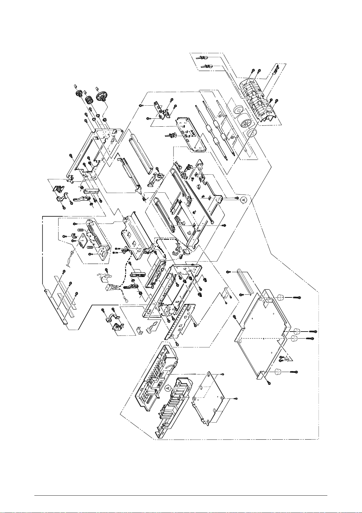
Figure 3-3
41057601TH Rev.1 45/
Page 46

Figure 3-4
41057601TH Rev.1 46/
Page 47

3.3 How to Change Parts
Printer Unit
Cover Assy Rear (3.3.1)
Cover (3.3.8)
Belt Cassette Assy (3.3.32)
Heat Unit Assy (3.3.40)
Oil Roller Assy (3.3.41)
Holder LED Assy (3.3.45)
Frame Assy Upper (3.3.5) Plate Support Assy (3.3.6) Limiter 2Way (L), (R) (3.3.7)
/Plate Guide (L) ,(R)
Motor Fan (80-25) (3.3.2)
Paper Eject Assy (3.3.3)
Cover Assy Stacker (3.3.4)
Guide Eject FD Assy
PCB Assy : PCE (3.3.9)
Power Supply Unit (3.3.16)
Hopping Motor (3.3.19)
Feeder Unit Front (3.3.21)
Manual Hopper Assy (3.3.22)
PCO PCB (3.3.29)
Holder Gear Toner Assy (3.3.30)
Plate Latch Lever (FD) (3.3.31)
High Voltage Power Supply Unit (3.3.33)
Eraser BKT Assy (3.3.34)
Lever Lock Heat L, R (3.3.42)
PXL PCB (3.3.43)
Heat Unit Guide Assy (3.3.44)
Moter Fan (3.3.10)
PXF PCB / PX4 PCB (3.3.11)
Gear Heat Assy (3.3.12)
Main Motor (A),(B) Assy (3.3.13)
Gear Oneway (Z30) (3.3.14)
Motor Assy BT (3.3.15)
Sensor Assy BOX Toner (3.3.17)
Square-shaped connector (3.3.18)
Gear One-way (3.3.20)
Guide Paper Input Assy (3.3.23)
Lever Input Sensor (3.3.24)
Lever 2nd Feed Sensor
Roller Registration
Roller Assy Hopping (3.3.25)
PXU PCB/PXM PCB (3.3.27)
Roller Hopping (3.3.26)
Paper End Lever (3.3.28)
Shaft Link, Lever Link (3.3.35)
Contact (BL-R, CL-R) Assy (3.3.36)
Contact (BL-L, CL-L) Assy (3.3.37)
Contact SB Assy (3.3.38)
PXC PCB (3.3.39)
This section explains how to change parts and assemblies appearing in the disassembly diagram
below.
41057601TH Rev.1 47/
Page 48

3.3.1 Cover Assy Rear
1. Unscrew 2 screws 1 then lift the cover assy rear 2 a little bit, then remove the cover assy
rear by releasing the lock of two claws.
Figure 3.3.1 Cover Assy Rear
2
1
41057601TH Rev.1 48/
Page 49

3.3.2 Motor-Fan (80-25)
1. Remove the cover assy rear. (See 3.3.1)
2. Unscrew 2 screws 1.
3. Detach the motor-fan 2 from the guide with its right side lifted then draw the motor-fan.
4. Unplug the cable 3 then remove the motor-fan 2.
3
Figure 3.3.2 Motor-Fan (80-25)
2
1
41057601TH Rev.1 49/
Page 50

3.3.3 Paper Eject Assy
The paper eject assy comprises the frame eject assy and the guide paper eject assy.
1. Remove the cover assy rear. (See 3.3.1)
2. Open the top cover.
3. Unscrew 4 screws 1 then remove the frame eject assy 2.
4. Remove the guide paper eject assy 3 by releasing the lock of one claw.
3
claw
Figure 3.3.3 Paper Eject Assy
1x2
2
1x2
41057601TH Rev.1 50/
Page 51

3.3.4 Cover Assy Stacker, Guide Eject FD Assy
Remove the belt cassette assy and the heat unit assy.
1. Remove the cover assy rear. (See 3.3.1)
2. Detach the cable from the cable clamp 1 by releasing its lock.
3. Unscrew 8 screws 2 then remove the cover assy stacker.
4. Unscrew 4 screws 4 then remove the guide eject FD assy 5.
3
2x6
4
5
4x4
1
2x2
Cable
Figure 3.3.4 Cover Assy Stacker, Guide Eject FD Assy
41057601TH Rev.1 51/
Page 52

3.3.5 Frame Assy Upper
1. Remove the cover assy rear. (See 3.3.1.)
2. Remove the cover assy stacker. (See 3.3.4.)
3. Remove the holder LED assy. (See 3.3.45.)
4. Detach the cable from the cable clamp 1 by releasing its lock.
5. Remove connections of 4 connector cables 2 and 4 cables 3.
6. Unscrew 4 screws 4 then remove the PCB 5.
7. Unscrew 2 screw 6 then remove Holder 7 by releasing the clamp of the claw.
8. Unscrew 4 screws 8 then remove the frame assy upper 9.
8x2
4x4
9
5
6
2
7
3
7
8x2
1
Cable
Figure 3.3.5 Frame Assy Upper
41057601TH Rev.1 52/
Page 53

3.3.6 Plate Support Assy
The plate support assemblies are provided right and left. The method of those replacements is the
same.
1. Remove the heat unit assy. (See 3.3.40)
2. Remove the cover assy rear. (See 3.3.1)
3. Remove the cover assy stacker. (See 3.3.4)
4. Remove the frame assy upper. (See 3.3.5)
5. Detach the cable from the cable clamp 1 by releasing its lock.
6. Unscrew 2 screws 2 then remove the plate support assy 3.
(Be careful not to lose the spring 4 which is removed with the plate support assy 3.)
4
4
3
2
2
3
1
Cable
Figure 3.3.6 Plate Support Assy
41057601TH Rev.1 53/
Page 54

3.3.7 Limiter 2way (L), (R) / Plate Guide (L) , (R)
1. Remove the plate support assy (L) and (R). (See 3.3.6)
2. Unscrew 2 screws 1 then remove the limiter 2way (L) 2 and the plate guide (L) 3.
3. Unscrew 2 screws 4 then remove limiter 2way (R) 5 and the plate guide (R) 6.
4
1
3
2
Figure 3.3.7 Limiter 2way (L), (R) / Plate Guide (L) , (R)
5
6
41057601TH Rev.1 54/
Page 55

3.3.8 Cover
Describes the method of removing the cover assy side (L)/(R), cover assy OP panel, cover front
(L)/(R) and the cover rear (L).
Remove the belt cassette assy and the heat unit assy.
1. Remove the cover assy rear. (See 3.3.1)
2. Remove the cover assy stacker. (See 3.3.4)
3. Unscrew 2 screws 1 then remove the frame side (L) 2.
4. Unscrew 2 screws 3 then release the lock of the claw with the cover assy side (R) 4 lifted
5. Unplug the operator panel cable 5 from the PCM PCB.
6. Open the FDR unit front in the arrow direction.
7. Unscrew 2 screws 6 then remove the cover assy OP panel7.
8. Unscrew 2 screws 8 then release the lock of the claw with the cover front (R) 9 pushed up
9. Unscrew 2 screws 0 then remove the cover front (L) A.
10. Unscrew 2 screws B then remove the cover rear (L) C.
11. Pull off the film E glued on the cassette guide.
11. Release the engagement with the guide by lifting the cover assy side (L) D, then remove the
a little bit, then remove the cover assy side (R).
then remove the cover front (R).
cover assy side (L).
C
6
1
7
5
3
2
4
8
9
A
Pushed Up
E
B
A
FDR Unit Front
A
D
0
Figure 3.3.8 Cover
41057601TH Rev.1 55/
Page 56

3.3.9 PCB Assy : PCE
Remove the belt cassette assy and the heat unit assy.
1. Open the top cover.
2. Unscrew 2 screws 1 to release the lock of the claw by lifting the cover assy side (R) 2 a little
bit, then remove the cover assy side (R).
3. Unscrew 2 screws 8 to remove the plate shieled (CU) 9.
4. Unscrew 3 screws 3 to remove the plate shield 4.
5. Unplug the operator panel cable 5 from the PCE PCB.
6. Unscrew 8 screws 6 to remove the PCB assy : PCE 7.
8
9
1
7
5
6
Figure 3.3.9 PCB Assy : PCR
2
3
4
41057601TH Rev.1 56/
Page 57

3.3.10 Motor Fan (CU)
1. Open the top cover.
2. Remove the cover assy side (R), frame side (L), cover assy OP panel and the cover front (R).
(See 3.3.8)
3. Unplug the cable 1 and unscrew 2 screws 2, 2 collars 4 and then remove the motor fan
(CU) 3.
3
1
4
2
Figure 3.3.10 Motor Fan (CU)
41057601TH Rev.1 57/
Page 58

3.3.11 PXF PCB/PX4 PCB
Since the PXF PCB and PX4 PCB are connected with each other via the connector, remove them
at the same time.
1. Remove the PCB assy : PCE. (See 3.3.9)
2. Unscrew 5 screws 1 then remove the cover CU2.
3. Unplug all the cables 5 connected to the PXF PCB 3 and PX4 PCB 4.
4. Unscrew 5 screws 6 then remove the PXF PCB3 and PX4 PCB4 at the same time.
3
5
5
5
5
6
5
5
5
2
4
5
1
6
1
1
1
Figure 3.3.11 PXF PCB/PXS PCB
41057601TH Rev.1 58/
Page 59

3.3.12 Gear Heat Assy
1. Remove the cover assy side (R), cover assy OP panel, cover front (R) and the cover rear (L).
(See 3.3.8)
2. Remove the cover CU then unplug all the cables connected to the PXS PCB and unscrew 3
screws. (See 3.3.11)
3. Unplug all the cables connected to the PXF PCB then remove the PX4 PCB. (See 3.3.11)
(Be careful not to damage the connector when unplugging cables connected to the PXF
PCB.)
4. Remove the heat unit assy. (See 3.3.40)
5. Remove the guide paper eject assy. (See 3.3.3)
6. Remove the motor fan (80-25). (See 3.3.2)
7. Unscrew 5 screws 1 and unplug the cable 2 then remove the guide heat assy 3.
8. Unscrew 2 screws 4 then remove the motor (ID)5.
1
1
1
5
Figure 3.3.12 Gear Heat Assy
4
3
2
41057601TH Rev.1 59/
Page 60

3.3.13 Main Motor (A), (B) Assy
1. Remove the PXF PCB and PX4 PCB. (See 3.3.11)
2. Unscrew 4 screws 8 and remove 4 plate-Earth 9 and 4 lever Up/Dn 2 1.
3. Unplug all the cables 2 connected and unscrew 4 screws 3, then remove the main motor
(A) assy 4.
4. Unplug all the cables 5 connected and unscrew 3 screws 6, then remove the main motor
(B) assy 7.
5
2
2
4
3
2
3
1
7
9
5
1
8
6
5
1
6
1
9
8
Figure 3.3.13 Main Motor (A), (B) Assy
41057601TH Rev.1 60/
Page 61

3.3.14 Gear One-way (Z30)
Four gear one-ways (Z30) are provided but the method of those replacements is the same. Do not
disassemble the gear one-ways (Z30) because they are assemblies requires adjustment.
1. Remove the PCB assy : PCM. (See 3.3.9)
2. Remove the cover CU. (See 3.3.11)
3. Remove the 4 Plate-Earth and 4 lever Up/Dn 2. (See 3.3.13)
4. Release the lock with the shaft by spreading the claw, then remove the gear one-way (Z30)
1.
[Notice for mounting]
Mount the gear one-way (Z30) by fitting it with the shaft link turned in the arrow direction.
Shaft link
Figure 3.3.14 Gear One-way (Z30)
Claw
1
41057601TH Rev.1 61/
Page 62

3.3.15 Motor Assy BT
1. Remove the main motor (B) assy. (See 3.3.13)
2. Unplug 2 cables 1 connected and unscrew 2 screws 2, then remove the motor assy BT 3.
Figure 3.3.15 Motor Assy BT
3
1
2
41057601TH Rev.1 62/
Page 63

3.3.16 Power Supply Unit, Holder Inlet, Sheet Insulation
1. Remove the motor-fan (80-25). (See 3.3.2)
2. Remove the frame side (L), the cover assy side (R) and the cover rear (L). (See 3.3.8)
3. Unplug the cable 1.
4. Remove the holder inlet 3 by unscrewing 2 screws 2, then remove the power switch 4 and
unplug the AC socket 5.
5. Draw the power supply unit 7 by unscrewing 3 screws 6, then unplug the cable 8.
1
6
8
7
5
4
3
2
Figure 3.3.16 Power Supply Unit, Holder Inlet, Sheet Insulation
41057601TH Rev.1 63/
Page 64
3.3.17 Sensor Assy Box Toner
1. Remove the power supply unit. (See 3.3.16)
2. Unscrew the screw 1 then remove the sensor assy box toner 2 together with the bracket
3.
3. Unscrew the screw 4 then remove the sensor assy box toner 2.
Figure 3.3.17 Sensor Assy Box Toner
3
2
4
1
41057601TH Rev.1 64/
Page 65

3.3.18 Square-shaped Connector
Remove the heat unit assy.
1. Draw the power supply unit. (See 3.3.16) (Do not remove the power switch and AC socket
from the holder inlet.)
2. Unplug the cable 1.
3. Remove cable 2, screw 5 bracket 6 and cable 7 in order and then take off SW from bracket
6 to pull off square-shaped connector 4.
6
3
7
5
4
1
2
Figure 3.3.18 Square-shaped Connector
41057601TH Rev.1 65/
Page 66

3.3.19 Hopping Motor
1. Remove the cover assy side (R), cover assy OP panel and the cover front (R). (See 3.3.8)
2. Unscrew 2 screws 1 and unplug the cable 2, then remove the bracket hopping motor 3.
(Be careful not to lose the gears 5, 6 and 7 which slip off at this time.)
3. Unscrew 2 screws 8 then remove the hopping motor 3.
3
1
6
8
7
8
5
2
3
Figure 3.3.19 Hopping Motor
41057601TH Rev.1 66/
Page 67

3.3.20 Gear One-way
1. Remove the bracket hopping motor. (See 3.3.19)
2. Remove the spacer 4 first and release the locks with the shaft by spreading the claws of the
gear one-way 1, 2 and 3, then remove the gear one-ways.
3
Figure 3.3.20 Gear One-way
2
4
4
1
Claw
4
41057601TH Rev.1 67/
Page 68

3.3.21 Feeder Unit Front
1. Remove the cover assy side (R), cover assy OP panel, cover front (R) and the cover front (L).
(See 3.3.8.)
2. Remove the cover CU. (See 3.3.11)
3. Unscrew the screw 8 and remove the cable 9.
4. Unplug the cable 1 and unscrew the screw 2, then remove the bracket FF shaft 3.
5. Remove 2 E-rings 4 then remove the feeder unit front 5.
6. Unscrew each 2 screws 6 then remove 2 bracket FF links 7.
4
7
5
6
4
6
7
9
3
PXF
PX4
1
2
8
Figure 3.3.21 Feeder Unit Front
41057601TH Rev.1 68/
Page 69

3.3.22 Manual Feed Hopper Assy
1. Open the manual feed hopper assy.
2. Release the engagement between the holder and the link then remove the manual feed
hopper assy. (Be careful not to damage the holder.)
Link
Holder
1
Figure 3.3.22 Manual Feed Hopper Assy
41057601TH Rev.1 69/
Page 70

3.3.23 Guide Paper Input Assy
1. Remove the cover assy OP panel, cover front (R) and the cover front (L). (See 3.3.8)
2. Remove the feeder unit front. (See 3.3.21)
3. Unscrew 4 screws 1 then draw out the guide paper input assy 2 from the left side by rotating
its upper part . (Be careful not to damage the lever sensor resist.)
Lever Sensor Resist
1
2
1
Figure 3.3.23 Guide Paper Input Assy
41057601TH Rev.1 70/
Page 71

3.3.24 Two Lever Input Sensors, Lever 2nd Feed Sensor
1. Remove the guide paper input assy. (See 3.3.23)
2. Release the engagement with the guide by pressing 2 lever input sensors 2 in the arrow
direction, then remove them.
3. Release the engagement with the guide by pressing the lever 2nd feed sensor 2 in the arrow
direction, then remove the sensor.
1
2
Figure 3.3.24 Two Lever Input Sensors, Lever 2nd Feed Sensor
41057601TH Rev.1 71/
Page 72
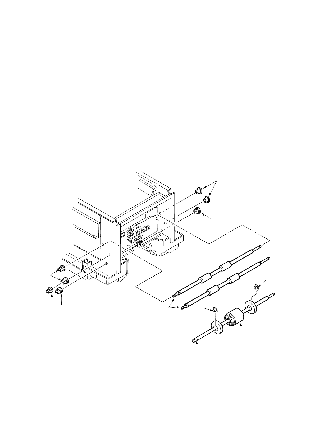
3.3.25 Roller Registration, Roller Assy Hopping
1. Remove the guide paper input assy. (See 3.3.23)
2. Remove the bracket hopping motor. (See 3.3.19)
3. Remove the gear one-way. (See 3.3.20)
4. Remove the holder gear toner assy. (See 3.3.30)
[Removal of the roller registration]
5. Remove the gear 1 and 2 bushes 2 and 2 bearings 3, then 2 roller registrations 4.
[Removal of the roller assy hopping]
6. Remove the bush 5 and the bearing 6.
7. Remove E-rings 9 of the sub-roller hopping at both sides of hopping roller and then release
the lock of the roller hopping 7 with the shaft 8 by spreading the claw, then remove the roller
hopping from the left side by sliding the shaft 8 in the arrow direction. (Be careful not to lose
the knock-pin for fastening the roller hopping 7, which slips off together.)
3
2
1
5
4
6
9
9
7
8
Figure 3.3.25 Roller Registration, Roller Assy Hopping
41057601TH Rev.1 72/
Page 73

3.3.26 Roller Hopping
1. Remove the roller assy hopping. (See 3.3.25) and remove the 2 sub-roller hopping guide 3 .
(Be careful not to lose the knock-pin which slips off together when removing the roller assy
hopping.)
2. Detach the roller hopping 2 from the shaft 1.
Knock-pin
1
Claw
3
2
3
Figure 3.3.26 Roller Hopping
41057601TH Rev.1 73/
Page 74
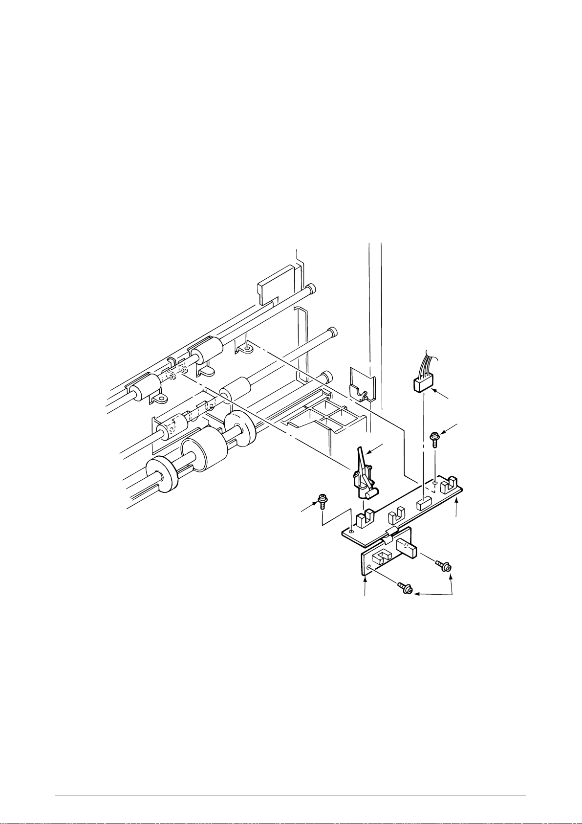
3.3.27 PXU PCB/PXM PCB, Lever Resist Sensor
Since the PXU PCB and PXM PCB are connected with each other via the cable, remove them at
the same time.
1. Remove the guide paper input assy. (See 3.3.23)
2. Unscrew 4 screws 1 and unplug the cable 2, then remove the PXU PCB 3 and PXM PCB
4 at the same time.
3. Remove the lever resist sensor 5 by releasing the engagement with the guide.
5
1
3
PXU PCB
Figure 3.3.27 PXU PCB/PXM PCB, Lever Resist Sensor
2
1
4
PXM PCB
1
41057601TH Rev.1 74/
Page 75

3.3.28 Paper End Lever
1. Remove the guide paper input assy. (See 3.3.23)
2. Remove the paper end lever 1 by releasing the engagement with the guide.
Figure 3.3.28 Paper End Lever
1
41057601TH Rev.1 75/
Page 76
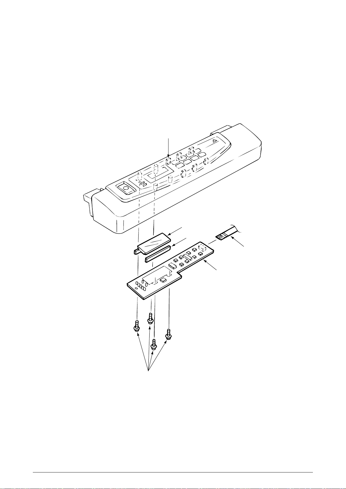
3.3.29 PCO PCB (Operator Panel)
1. Remove the cover assy side (R) and the cover assy OP panel. (See 3.3.8)
2. Unscrew 4 screws 1 and unplug the operator panel cable 2.
6. Remove the PCO PCB 3 by releasing 6 claws.
(Be careful not to drop the LCD (Liquid Crystal Display) 4 and 5 which are detached
together.)
Claw (six)
1
4
5
2
3
Figure 3.3.29 PCO PCB (Operator Panel)
41057601TH Rev.1 76/
Page 77

3.3.30 Holder Gear Toner Assy
1. Remove the cover assy side (R), cover assy OP panel, cover front (R) and the cover rear (L).
(See 3.3.8)
2. Unplug the cable 1 and unscrew the screw 2, then remove the holder gear toner assy 3.
2
3
1
Figure 3.3.30 Holder Gear Toner Assy
41057601TH Rev.1 77/
Page 78

3.3.31 Plate Latch Lever (FD), Spring Latch Lever (FD)
Remove the belt cassette assy.
1. Remove the cover assy side (R), cover assy OP panel, cover front (R) and the cover front (L).
(See 3.3.8)
2. Open the cover CU. (See 3.3.11)
3. Unplug the cable 1.
4. Unscrew 4 screws 4 then remove the stay upper (front) 5.
5. Unscrew 2 screws 2 then remove the bracket SW (side) 3.
6. Remove the plate latch lever (FD) 6 and spring latch lever (FD) 7 with the side frames
spread. (Be careful not to spread the frames too much.)
7
4
6
2
Frame
Frame
3
2
5
4
1
Figure 3.3.31 Plate Latch Lever (FD), Spring Latch Lever (FD)
41057601TH Rev.1 78/
Page 79

3.3.32 Belt Cassette Assy
1. Open the Top cover.
2. Release the lock by drawing the cover knob then open the cover assy side (L).
3. Turn the waste toner box (box toner assy) 1 to the left by pressing it down, then remove it.
4. Draw out the belt cassette assy 2 by lifting it a little bit with its handle.
Cover knob
2
1
Cover assy side (L)
Figure 3.3.32 Belt Cassette Assy
41057601TH Rev.1 79/
Page 80

3.3.33 High Voltage Power Supply Unit, Bracket HV (BT) Assy
1. Remove the belt cassette assy. (See 3.3.32)
2. Unscrew 2 screws 1 with the stacker cover opened, then remove the plate HV 2.
3. Unplug the cable 3 and 7 codes 4.
4. Unscrew 2 screws 5 then remove the high voltage power supply unit 6.
5. Remove the bracket HV (BT) assy 7.
1
2
4
5
3
7
5
6
Figure 3.3.33 High Voltage Power Supply Unit, Bracket HV (BT) Assy
41057601TH Rev.1 80/
Page 81

3.3.34 Eraser Bracket Assy, Eraser Bracket (KCM) Assy
1. Remove the belt cassette assy. (See 3.3.32.)
2. Open the stacker cover.
3. Remove four screws 5 and then remove the Plate Blind 6.
[Removing the eraser bracket assy]
4. Remove the screw 1 and the connector 2.
5. Release the screw 7 and then remove the eraser bracket assy 3
[Removing the eraser bracket (KCM) assy]
5. Remove the screw 1 and the connector 2.
6. Release the lock of the claw then release the engagement with the bracket sensor T (KCM)
(See 3.3.35 2.)
7. Release the screw 7 and then remove the eraser bracket (KCM) assy 4 and unplug the
cable 2 then remove the eraser bracket (KCM) assy.
1
1
4
2
3
2
5
6
5
7
Figure 3.3.34 Eraser Bracket Assy, Eraser Bracket (KCM) Assy
41057601TH Rev.1 81/
Page 82
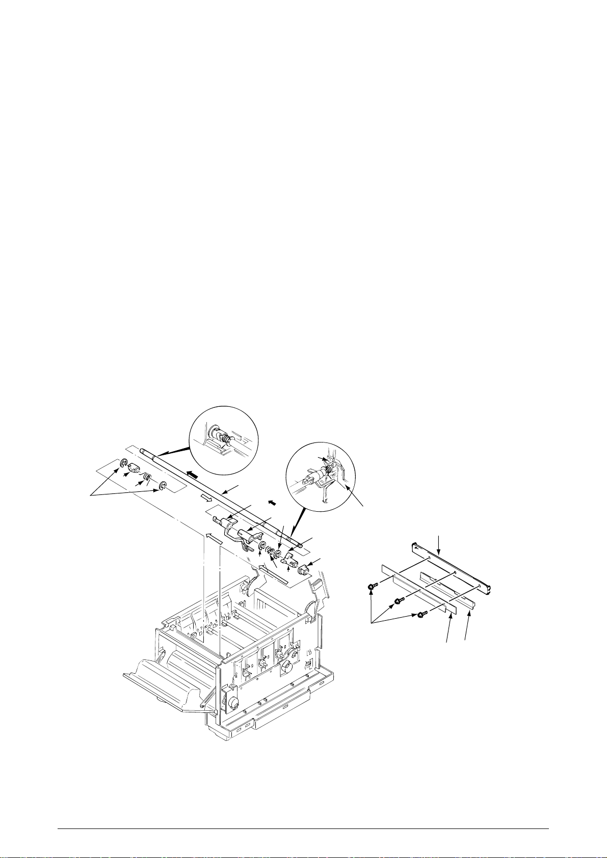
3.3.35 Shaft Link
1. Remove the eraser bracket assy. (See 3.3.34.)
2. Remove the gear one-way (Z30). (See 3.3.14.)
3. Remove the E-ring 3 by sliding the sensor assy T (KCM) 1 and bracket sensor T (KCM) 2
together in the arrow (A) direction. When removing shaft (K) assy, remove 3 screws then
remove the Heat Sink-801 B. Release the lock of the claw then remove the plate shield Heat
C by sliding .
4. Release the engagement between the lever Up/Dn and boss A of the lever link (R) 5 by
sliding the spring support (R) 4, lever link (R) 5 and the bearing 6 together in the arrow (B)
direction.
(Keep on sliding until the lever link (R) 5 reaches the end of D-cut part of the shaft link 7.)
5. Draw out the entire shaft link 7 by pressing it in the arrow (C) direction and turning its left side
under the contact (BL L) assy.
6. Detach the sensor assy T (KCM) 1, bracket sensor T (KCM) 2, spring support (R) 4, lever
link (R) 5 and the bearing 6 from the shaft link 7.
7. Remove 2 E-rings 8 then remove the spring support (L) 9 and lever link (L) 0.
[Notice for mounting]
- Engagement between the lever Up/Dn and boss A of the lever link (R) 5:
Mount the spring support (L) 9 and lever link (L) 0 in the predetermined positions, then clamp
the boss A of lever link (R) 5 with the lever Up/Dn by adding rotating power on the spring
support (L) 9 by rotating the shaft link 7.
- Mounting of the spring support (R) 4:
Clamp the spring support (R) 4 at the predetermined positions in the lever link (R) 5 and the
contact BKT (R).
8
0
9
(C)
Slide 7
(D)
Remove 7
(A)
Slide 1, 2
7
1
3
(B)
Slide 4, 5 and 6
2
Boss A
Lever Up/Down
3
Boss A
6
4
5
A
Stay EP
B
C
Figure 3.3.35 Shaft Link
41057601TH Rev.1 82/
Page 83

3.3.36 Contact (BL-R) Assy, Contact (CL-R) Assy
1. Remove the gear one-way (Z30). (See 3.3.14)
2. Remove the motor assy BT. (See 3.3.15)
3. Remove the high voltage power supply unit. (See 3.3.33)
4. Remove the shaft link. (See 3.3.35)
[Removal of the contact (BL-R) assy]
5. Unscrew 2 screws 1 and unplug the cable 2, then remove the contact (BL-R) assy 3.
[Removal of the contact (CL-R) assy]
6. Unscrew 2 screws 4 then remove the contact (CL-R) assy 5.
Contact (CL-R) Assy
Contact (BL-R) Assy
4
5
1
3
2
Figure 3.3.36 Contact (BL-R) Assy, Contact (CL-R) Assy
41057601TH Rev.1 83/
Page 84

3.3.37 Contact (BL-L) Assy, Contact (CL-L) Assy
1. Remove the shaft link. (See 3.3.35)
[Removal of the contact (BL-L) assy]
2. Unscrew 2 screws 1 then remove the contact (BL-L) assy 2.
[Removal of the contact (CL-L) assy]
3. Unscrew 2 screws 3 then remove the contact (CL-L) assy 4.
Contact (BL-L) Assy
Contact (CL-L) Assy
4
2
3
1
Figure 3.3.37 Contact (BL-L) Assy, Contact (CL-L) Assy
41057601TH Rev.1 84/
Page 85

3.3.38 Contact SB Assy
1. Remove the contact (BL-L) assy and contact (CL-L) assy. (See 3.3.37)
2. Unscrew 3 screws 1 then remove the plate blink 2.
3. Unplug 7 codes 3.
4. Unscrew 3 screws 4 then remove the contact SB assy 5.
5
2
1
3
4
3
3
Figure 3.3.38 Contact SB Assy
41057601TH Rev.1 85/
Page 86

3.3.39 PXC PCB
1. Remove the contact (BL-R) assy and contact (CL-R) assy. (See 3.3.36)
2. Remove the contact (BL-L) assy and contact (CL-L) assy. (See 3.3.37)
3. Remove the hopping motor. (See 3.3.19)
4. Remove the motor assy BT. (See 3.3.15)
5. Remove the gear heat assy. (See 3.3.12)
6. Remove the roller assy hopping. (See 3.3.25)
7. Remove the holder gear toner assy. (See 3.3.30)
8. Remove the high voltage power supply unit. (See 3.3.33)
9. Unplug the inlet AC. (See 3.3.16)
10. Unscrew 9 screws 1 then remove the guide cassettes (L) 2 and (R) 3 together.
11. Unscrew the screw 4 then remove the switch 5.
12. Unscrew the screw 6 then remove the PXC PCB 7.
1
1
1
1
1
1
7
6
4
3
5
2
Figure 3.3.39 PXC PCB
41057601TH Rev.1 86/
Page 87

3.3.40 Heat Unit Assy
1. Open the stacker cover.
2. Release the lock by turning down the lever lock heat guides (blue) on both sides, then lift the
heat unit assy 1 and remove it.
1
Lever Lock Heat Guide
Figure 3.3.40 Heat Unit Assy
41057601TH Rev.1 87/
Page 88

3.3.41 Oil Roller Assy
1. Remove the heat unit assy. (See 3.3.40)
2. Release the lock by turning down the lever in the arrow (A) direction, then slide the oil roller
assy 1 with its right side lifted and remove it.
1
(A)
Lever
Figure 3.3.41 Oil Roller Assy
41057601TH Rev.1 88/
Page 89

3.3.42 Lever Lock Heat (L)/(R), Guide Side Heat, Spring Lock
Removing methods for right side and left side of each part are the same. Here describes the method
for right side.
1. Remove the heat unit assy. (See 3.3.40)
2. Unscrew 2 screws 1 then remove the guide side heat 2.
3. Remove the E-ring 3 then lever lock heat (R) 4.
(Be careful not to lose the spring lock 5 which slips off together.)
4
5
3
1x2
2
Figure 3.3.42 Lever Lock Heat (L)/(R), Guide Side Heat, Spring Lock
41057601TH Rev.1 89/
Page 90

3.3.43 PXL PCB
1. Remove the paper eject assy. (See 3.3.3)
2. Remove the belt cassette assy. (See 3.3.32)
3. Remove the heat unit assy. (See 3.3.40)
4. Unplug the cable 1 and the screw 2, then remove PXL PCB 3.
5. Release the lock of the claw then remove the sensor cover 4.
2
1
4
3
Figure 3.3.43 PXL PCB
41057601TH Rev.1 90/
Page 91

3.3.44 Heat Unit Guide Assy
1. Remove the cover assy rear. (See 3.3.1)
2. Remove the paper eject assy. (See 3.3.3)
3. Remove the gear heat assy. (See 3.3.12)
4. Remove the belt cassette assy. (See 3.3.32)
5. Open the stacker cover and remove the heat unit assy. (See 3.3.40)
6. Unscrew 4 screws 1 then remove the heat unit guide assy 2.
1
1
2
Figure 3.3.44 Heat Unit Guide Assy
41057601TH Rev.1 91/
Page 92

3.3.45 Holder LED Assy, LED Head
Remove the belt cassette assy and the heat unit assy.
1. Unplug the cable 1.
2. Remove the LED head 3 by spreading the holder LED assy 2 a little bit.
(Be careful not to lose the spring 4 which slips off together.)
3. Remove the holder LED assy 2 by spreading the A-part of the guide holder a little bit with
a flat blade screwdriver.
(Be careful not to lose the spring 5 which slips off together.)
Guide Holder
3
5
A
2
5
4
1
Figure 3.3.45 Holder LED Assy, LED Head
41057601TH Rev.1 92/
Page 93

4. ADJUSTMENTS
Adjustments are carried out by key operations on the operator panel, by software operation panel,
and by EEPROM of PU (PX4-PCB) setting.
This page printer supports three maintenance modes. Select and set a maintenance mode fit for
the adjustment.
4.1 Maintenance Modes and Their Functions
4.1.1 User maintenance mode
To set the user maintenance mode, turn on the power switch of the page printer while pressing on
the MENU key.
• Functions
- Menu reset - Hex dump
- Resource save area - Receive buffer size
- Operator panel menu disable - X adjust
- Y adjust
(a) Menu reset
1 Resets all Menu Level 1 settings to the default settings (which have been factory-set).
2 Resets all executable Emulation menu items (including options) to factory-set default
emulation items.
(b) Hex dump
1 Receives data from the host computer and dumps it in a hexadecimal format.
2 When one page of data or more comes from the host, printing automatically starts.
To print out data of less than one page, press the ONLINE key to set the offline state
and press the EJECT key. Printing starts.
3 To exit this mode, shut off power to the page printer.
(This is the only one way to exit this mode.)
(c) Resource save area
Sets the resource saving area. This menu item appears when the option PS SIMM and
RAM increases, the selectable size will also increase (When adding a RAM over
24Mbytes, the selection can be made up to 22.5Mbytes). The size upon auto will also
increase if the size of the add-on RAM increases.
(d) Receive buffer
Sets the receive buffer. The data transmission time from the upper command will
decrease when set to a high value, but memory overflow will occur easier. Memory will
be restructured with this change, and the contents of all download fonts, PCL macro, and
PodtScript will be lost.
(e) Operator panel menu disable
Enables or disables the menu functions (Menu1, Menu2, Tray Type, Power Save, and
Paper Size) of the operator panel.
(f) X adjust
1 Corrects the position of the whole print image so that it may be perpendicular to the
movement of paper (at intervals of 0.25mm).
2 The print image exceeding the specified printable area is clipped.
(g) Y adjust
1 Corrects the position of the whole print image so that it may be parallel to the
movement of paper (at intervals of 0.25mm).
2 The print image exceeding the specified printable area is clipped.
41057601TH Rev.1 93/
Page 94

User maintenance mode memu system
Category Selection DF After pressing ENTER key After completing the process
MENU MENU MENU
RESET RESETTING RESET
HEX DUMP ON-LINE
HEX DUMP
RESOURCE SAVE AUTO *
OFF
400KB
900KB
1.6MB
2.5MB
•
•
•
19.6MB
22.5MB
RECEIVE BUFFER AUTO *
OFF
100KB
512KB
1MB
ECP ENABLE *
DISABLE
OP MENU ENABLE * SETTING EEPROM
DISABLE
X ADJUST 0 mm * SETTING EEPROM
+0.25 mm
+0.50 mm
~
+2.00 mm
-2.00 mm
-1.75 mm
~
-0.25 mm
Y ADJUST 0 mm * SETTING EEPROM
+0.25 mm
+0.50 mm
~
+2.00 mm
-2.00 mm
-1.75 mm
~
-0.25 mm
41057601TH Rev.1 94/
Page 95

4.1.2 System maintenance mode
To set the system maintenance mode, turn on the power switch of the page printer while pressing
on the Recover key.
Note: The system maintenance mode is hidden and not available to the user.
To exit this mode, press the ONLINE switch except during rolling ASCII continuous printing. Then
the RUN mode is set.
In the system maintenance mode, the category changes each time the MENU switch is pressed.
The last category wraps around to the first category. The system maintenance mode supports the
following functions:
• Page count display • Page count printing enable/disable
• Rolling ASCII continus prinitng • EEPROM reset
• HSP ERROR recovery • HSP ERROR count display
• HSP ERROR count reset
(1) Page count display
• The total number of pages counted at the engine is displayed on the LCD.
(2) Page count printing enable/disable
• This function selects whether to include (enable) or exclude (disable) the total number of
printed pages counted at the engine at the time of menu printing.
(3) Rolling ASCII continuous printing
• The rolling ASCII pattern is printed continuously for various engine tests.
• Press the ON-LINE key to cancel this mode.
(4) EEPROM reset
• All EEPROM areas including Menu level-2 to the factory default values.
• The following items are excluded
Head drive time setting
ENGINE Maintenance Item
Revision (Including Destination setting)
(5) HSP ERROR recovery
• Select HSP ERROR recovery function either recover or stop.
(6) HSP ERROR count
• Display total HSP ERROR count.
(7) HSP ERROR count reset
• Reset the HSP ERROR counter.
41057601TH Rev.1 95/
Page 96

System Maintenance mode menu system
Category Selection DF After pressing ENTER key After completing the process
PAGE CNT
nnnnnn
PAGE PRT DISABLE *
ENABLE
CONT PRT CONT PRT CONT PRT
PRINTING CANCELLED
(ON LINE SW Press)
EEPROM EEPROM EEPROM
RESET RESETTING RESET
HSPERR RECOVER * SETTING
STOP EEPROM
HSPERR
CNT nn
HSPERR HSPERR HSPERR
CNT RST RESETTING CNT RST
41057601TH Rev.1 96/
Page 97

4.1.3 Engine maintenance mode
To set the engine maintenance mode, turn on the power switch of
the page printer while pressing on the ENTER and FORM FEED keys. The engine maintenance
mode is set and “ENG MNT” is displayed on-screen.
Note: The engine maintenance mode is hidden and not available to the user.
To exit this mode, press the ONLINE switch. The operation mode is set. The engine maintenance
mode supports the following functions:
• Head drive time setting (YELLOW, MAGENTA, CYAN, BLACK)
• Drum count display (YELLOW, MAGENTA, CYAN, BLACK)
• Total drum count display (YELLOW, MAGENTA, CYAN, BLACK)
• Fuser count display
• Belt count display
• Oil roller count display
• Setting of standard tray paper feed length
• Setting of second tray paper feed length
• Setting of frontfeeder paper feed length
• Engine reset
(1) Head drive time setting (Yellow, Magenta, Cyan, and Black)
Sets the time of driving each LED head.
(2) Drum count display (Yellow, Magenta, Cyan, and Black)
Displays the number of revolutions of each EP drum counted by the engine on the LCD.
(3) Total drum count display (Yellow, Magenta, Cyan, Black)
Displays the total number of rotations at each color.
(4) Fuser count display
Displays the total number of pages by Fuser which have been counted by the engine.
(5) Belt count display
Displays the total number of pages by Belt which have been counted by the engine.
(6) Oil roller count display
Displays the counter of the oil roller.
(7) T1 position (Setting of standard tray paper feed length)
Sets a value for correcting the amount of paper feeding of the standard tray.
(8) T2 position (Setting of second tray paper feed length)
Sets a value for correcting the amount of paper feeding of the second tray.
(9) Engine reset
- Resets the contents of all EEPROM areas used by the engine with default values.
- Does not reset the following items:
LED head drive time
Menu level 1
Menu level 2
Operator Panel Menu Disable/Enable
Page Print Disable/Enable
41057601TH Rev.1 97/
Page 98

Engine maintenance mode memu system (1/2)
Category Selection DF After pressing ENTER key After completing the process
YELLOW LED HEAD No.1 SETTING EEPROM
No.2
No.16
No.17
No.32
MAGENTA LED HEAD No.1 SETTING EEPROM
No.2
No.16
No.17
No.32
CYAN LED HEAD No.1 SETTING EEPROM
No.2
No.16
No.17
No.32
BLACK LED HEAD No.1 SETTING EEPROM
No.2
No.16
No.17
No.32
41057601TH Rev.1 98/
Page 99

Engine maintenance mode menu system (2/2)
Category Selection DF After pressing ENTER key After completing the process
YELLOW DRMCNT
nnnn
Yellow DRMCNT
T nnnnnnn
MAGENTA DRMCNT
nnnn
Magenta DRMCNT
T nnnnnnn
CYAN DRMCNT
nnnn
Cyan DRMCNT
T nnnnnnn
BLACK DRMCNT
nnnn
Black DRMCNT
T nnnnnnn
FUSER COUNT
nnnn
BELT COUNT
nnnn
Oil Roller Count
nnnnnnn
T1 POSITION 0 mm * SETTING EEPROM
+1 mm
~
+7 mm
-8 mm
~
-1 mm
T2 POSITION 0 mm * SETTING EEPROM
+1 mm
~
+7 mm
-8 mm
~
-1 mm
FF POSITION 0 mm * SETTING EEPROM
+1 mm
~
+7 mm
-8 mm
~
-1 mm
ENGINE ENGINE ENGINE
RESET RESETTING RESET
41057601TH Rev.1 99/
Page 100

4.2 Adjustments after Parts Replacement
Adjustments required after parts replacement are listed below.
Adjustment and correction of color deviations are always required after parts are replaced.
Part replaced Adjustment required
LED head Correct color deviations.
Drum cartridge (Y, M, C, B, and K) Reset the drum counter and correct color deviations.
Fuser Unit Reset the fuser counter and correct™™ color deviations.
Belt cassette assembly Reset the belt counter and correct color deviations.
EEPROM (PU block) Correct color deviations.
Oil Roller Reset the oil roller counter.
Other parts Correct color deviations (if any).
4.2.1 Confirm the LED head driving time
Note: The OKICOLOR 8/ OKIPAGE 8c Plus, if a new LED HEAD is placed, reads the contents
of EEPROM within the LED HEAD, automatically re-setting the drive time. Therefore, the
re-setting of drive time is unnecessary, but a confirmation to the drive time re-set is
necessary.
- Display of illumination level of the LED head
405473
03234*********078TH
The trailing three digits of this number
indicates the illumination level of the LED head.
41057601TH Rev.1 100/
 Loading...