

Page 1

Line Thermal Printer
STAR Line Mode
Command
Specifications
Rev 0.01
Page 2

Table of Contents
1. INTERFACE CONFIGURATION ........................................................ 1-1
1-1) RS-232C Serial Interface ................................................... 1-1
1-1-1) Specifications (Conforming to RS-232)........................................... 1-1
1-1-2) Signal array and explanations according to interface connector pin ...................... 1-1
1-1-3) Communication protocol ..................................................... 1-2
1-2) Parallel Interfaces (Amphenol 36 pins) ..................................... 1-4
1-2-1) Specifications (Conforming to IEEE1284) ......................................... 1-4
1-2-2) Signal array and explanations according to interface connector pin ...................... 1-4
1-2-3) Signal output timing ........................................................ 1-5
1-2-4) Status specification ......................................................... 1-5
1-3) USB interface ..............................................................1-6
1-4) Ethernet interface ......................................................... 1-7
2. COMMAND FUNCTION LIST .......................................................... 2-1
3. COMMAND DETAILS ................................................................ 3-1
3-1) Explanation of Terms ....................................................... 3-1
3-2) Exception processing ....................................................... 3-2
3-3) Standard Command Details ................................................... 3-3
3-3-1) Font style and character set................................................... 3-3
ESC GS t n ..................................................................... 3-3
ESC GS = n1 n2 da1 da2...dak db1 db2...dbk ............................................ 3-4
ESC R n ....................................................................... 3-5
ESC / n ........................................................................ 3-6
ESC SP n ...................................................................... 3-7
ESC M ........................................................................ 3-8
ESC P ......................................................................... 3-8
ESC : ......................................................................... 3-8
ESC g ......................................................................... 3-9
3-3-2) Character Expansion Settings ................................................ 3-10
ESC i n1 n2 ....................................................................3-10
ESC W n ......................................................................3-11
ESC h n....................................................................... 3-11
SO .......................................................................... 3-12
DC4 ......................................................................... 3-12
ESC SO ...................................................................... 3-13
ESC DC4...................................................................... 3-13
3-3-3) Print mode .............................................................. 3-14
ESC E ........................................................................ 3-14
ESC F ........................................................................ 3-14
ESC – n....................................................................... 3-15
ESC _ n....................................................................... 3-15
ESC 4 ........................................................................ 3-16
ESC 5 ........................................................................ 3-16
SI ........................................................................... 3-17
DC2 ......................................................................... 3-17
3-3-4) Line spacing ............................................................. 3-18
LF ........................................................................... 3-18
CR .......................................................................... 3-18
ESC a n....................................................................... 3-18
ESC z n....................................................................... 3-19
ESC 0 ........................................................................ 3-19
ESC J n....................................................................... 3-20
ESC n ...................................................................... 3-20
3-3-5) Page control commands .................................................... 3-21
FF........................................................................... 3-21
ESC C n ...................................................................... 3-21
ESC C 0 n .....................................................................3-22
VT........................................................................... 3-23
ESC B n1 n2…nk NUL ............................................................3-24
ESC B NUL .................................................................... 3-24
3-3-6) Horizontal direction printing position ............................................ 3-25
ESC l n .......................................................................3-25
ESC Q n ...................................................................... 3-26
HT........................................................................... 3-26
ESC D n1 n2…nk NUL ............................................................ 3-27
ESC D NUL ....................................................................3-27
―――――――――――――――――――――――――――――――――――――――――― ――――――――――――――――――――――――――― ――――――――――――――――
STAR Line Mode Command Specifications 1-1
Page 3

ESC GS A n1 n2 ................................................................ 3-28
ESC GS R n1 n2 ................................................................ 3-28
ESC GS a n.................................................................... 3-29
3-3-7) Download............................................................... 3-30
ESC & c1 c2 n d1…d48 ........................................................... 3-30
ESC & c1 c2 n ..................................................................3-31
ESC % n ...................................................................... 3-31
3-3-8) Bit image graphics ........................................................ 3-32
ESC K n1 n2 d1...dk.............................................................. 3-32
ESC L n1 n2 d1...dk .............................................................. 3-33
ESC k n1 n2 d1...dk .............................................................. 3-34
ESC X n1 n2 d1...dk.............................................................. 3-35
3-3-9) Logo .................................................................. 3-36
ESC FS q n [x11 x12 y11 y12 d1...dk]1...[xn1 xn2 yn1 yn2 d1...dk]n ........................... 3-36
ESC FS p n m ..................................................................3-38
3-3-10) Bar code ............................................................... 3-39
ESC b n1 n2 n3 n4 d1...dk RS ...................................................... 3-39
3-3-11) Cutter control ............................................................ 3-41
ESC d n....................................................................... 3-41
3-3-12 External device drive....................................................... 3-42
ESC BEL n1 n2 ................................................................. 3-42
BEL.......................................................................... 3-43
FS........................................................................... 3-43
SUB ......................................................................... 3-44
EM .......................................................................... 3-44
3-3-13) Print settings ............................................................ 3-45
ESC RS d n .................................................................... 3-45
ESC RS r n .................................................................... 3-46
3-3-14) Status ................................................................. 3-47
ESC RS a n .................................................................... 3-47
ESC ACK SOH ................................................................. 3-48
ENQ ......................................................................... 3-48
EOT ......................................................................... 3-48
3-3-15) Chinese characters ........................................................ 3-49
ESC p ........................................................................ 3-49
ESC q ........................................................................ 3-49
ESC $ n....................................................................... 3-50
ESC s n1 n2 ................................................................... 3-51
ESC t n1 n2 ....................................................................3-51
ESC r c1 c2 d1...dk .............................................................. 3-52
3-3-16) Others ................................................................. 3-53
CAN ......................................................................... 3-53
ESC @ ....................................................................... 3-54
ESC GS # m N n1 n2 n3 n4 LF NUL .................................................. 3-55
ESC ? LF NUL .................................................................. 3-56
3-4) Raster Graphics Command Details ........................................... 3-57
ESC * r R...................................................................... 3-58
ESC * r A...................................................................... 3-59
ESC * r B...................................................................... 3-60
ESC * r C...................................................................... 3-60
ESC * r D n NUL ................................................................ 3-61
ESC * E n NUL ................................................................ 3-62
ESC * r F n NUL................................................................. 3-63
ESC * r P n NUL ................................................................ 3-64
ESC * r Q n NUL ................................................................ 3-64
ESC * r m l n NUL ............................................................... 3-65
ESC * r m r n NUL ............................................................... 3-65
ESC * r T n NUL................................................................. 3-66
ESC * r K n NUL ................................................................ 3-66
b n1 n2 data ................................................................... 3-67
k n1 n2 data ................................................................... 3-68
ESC * r Y n NUL ................................................................ 3-69
ESC FF NUL ................................................................... 3-70
ESC FF EOT ................................................................... 3-70
3-5) Black Mark Related Command Details ........................................ 3-71
ESC d n....................................................................... 3-71
―――――――――――――――――――――――――――――――――――――――――― ――――――――――――――――――――――――――― ――――――――――――――――
STAR Line Mode Command Specifications 1-2
Page 4

FF........................................................................... 3-72
ESC C n ...................................................................... 3-72
ESC C 0 n .....................................................................3-73
ESC c n....................................................................... 3-73
VT........................................................................... 3-74
ESC B n1 n2...nk NUL ............................................................ 3-74
ESC B NUL .................................................................... 3-74
3-6) USB Related Command Details ............................................... 3-75
3-7) 2 Color Printing Command Details .......................................... 3-76
ESC RS c n .................................................................... 3-76
ESC RS C n ................................................................... 3-77
ESC 4 ........................................................................ 3-79
ESC 5 ........................................................................ 3-79
ESC RS d n .................................................................... 3-80
ESC RS r n .................................................................... 3-81
ESC FS q n [x11 x12 y11 y12 d1...dk]1...[xn1 xn2 yn1 yn2 d1...dk]n ........................... 3-82
ESC FS p n m ..................................................................3-84
3-8) Presenter Related Command Details ......................................... 3-85
ESC SYN 0 n................................................................... 3-85
ESC SYN 1 n................................................................... 3-85
ESC SYN 3 n................................................................... 3-86
ESC SYN 4 n................................................................... 3-87
4. CHARACTER CODE TABLES .......................................................... 4-1
4-1) ANK Codes .................................................................. 4-1
4-2) Japanese Character Codes ................................................... 4-7
4-2-1) JIS Code Type (Conforming to JIS x0208-1983) .................................... 4-7
4-2-2) SHIFT-JIS Code Type ...................................................... 4-14
4-3) Chinese Character Codes (Conforming to GB2312) ............................ 4-20
4-4) Taiwanese Character Codes ................................................. 4-28
4-5) Korean Character Codes .................................................... 4-40
5. APPENDIX ....................................................................... 5-1
5-1) Appendix 1: Bar code specification details ................................. 5-1
5-1-1) Code 39 ................................................................. 5-1
5-1-2) Interleaved 2 of 5 .......................................................... 5-1
5-1-3) JAN/EAN/UPC ............................................................ 5-2
5-1-4) Code 128 ................................................................5-3
5-1-5) Code 93 ................................................................. 5-5
5-1-6) NW7 (CODERBAR) ........................................................ 5-5
5-2) Appendix 2: Status Specifications .......................................... 5-6
5-2-1) ENQ Command Status ...................................................... 5-6
5-2-2) EOT Command Status ...................................................... 5-6
5-2-3) Automatic Status .......................................................... 5-7
5-3) Appendix 3: Blank Code Page Configuration ................................. 5-14
6. SPECIAL APPENDIX COMMAND LIST BY MODEL ....................................... 6-1
―――――――――――――――――――――――――――――――――――――――――― ――――――――――――――――――――――――――― ――――――――――――――――
STAR Line Mode Command Specifications 1-3
Page 5

This specifications document describes the command specifications for the STAR LINE MODE on line thermal
printers. Information contained herein applies to models with the following conditions.
- Line thermal printers
- Interfaces:
- Parallel
- RS-232C
- USB
- Ethernet
< Applicable Models:>
TSP700
TSP600
TSP800
TUP900
―――――――――――――――――――――――――――――――――――――――――― ――――――――――――――――――――――――――― ――――――――――――――――
STAR Line Mode Command Specifications 1-4
Page 6
1. INTERFACE CONFIGURATION
1-1) RS-232C Serial Interface
1-1-1) Specifications (Conforming to RS-232)
Rating: RS-232C
Synch method: Start-Stop synchronization method
Handshake: DTR mode
Baud rates: 4800, 9600, 19200, 38400 bps (Set by DIP switches)
Bit length: 7, 8 bits (Set by DIP switches)
Parity: Yes/No (Set by DIP switches)
Parity bit: Odd/even (Set by DIP switches)
Stop bit: 1 bit (Fixed)
Signal polarity: Mark = logic 1 (-3 to -15 V)
Space = logic 0 (+3 to +15 V)
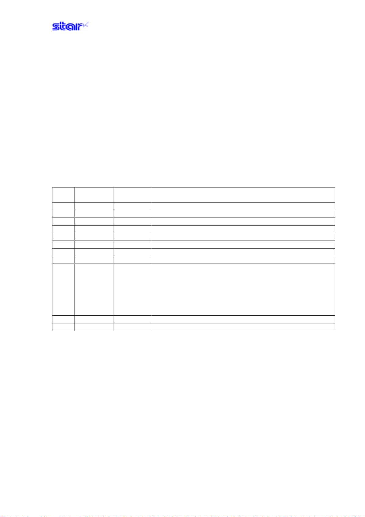
1-1-2) Signal array and explanations according to interface connector pin
<Signal Array and Functions>
Pin
No.
8-19 N.C - Not used
21-24 N.C Signal ground
Signal Name Signal
Direction
1 FG - Frame ground
2 TXD OUT Transmission data
3 RXD IN Reception data
4 RTS OUT Same as DTR
5 N.C - Not used
6 DSR IN Not used
7 SG - Signal ground
20 DTR OUT Data terminal ready signal (SPACE: printer is ready to receive.)
1) When in DTR mode:
When printer is ready to receive data: SPACE
2) When in XON/XOFF mode:
Always SPACE except in the following conditions.
1 Until communication is possible after a reset.
2 When test printing
25 /INIT IN Signal ground
Remarks
―――――――――――――――――――――――――――――――――――――――――― ――――――――――――――――――――――――――― ――――――――――――――――
STAR Line Mode Command Specifications 1-1
Page 7
1-1-3) Communication protocol
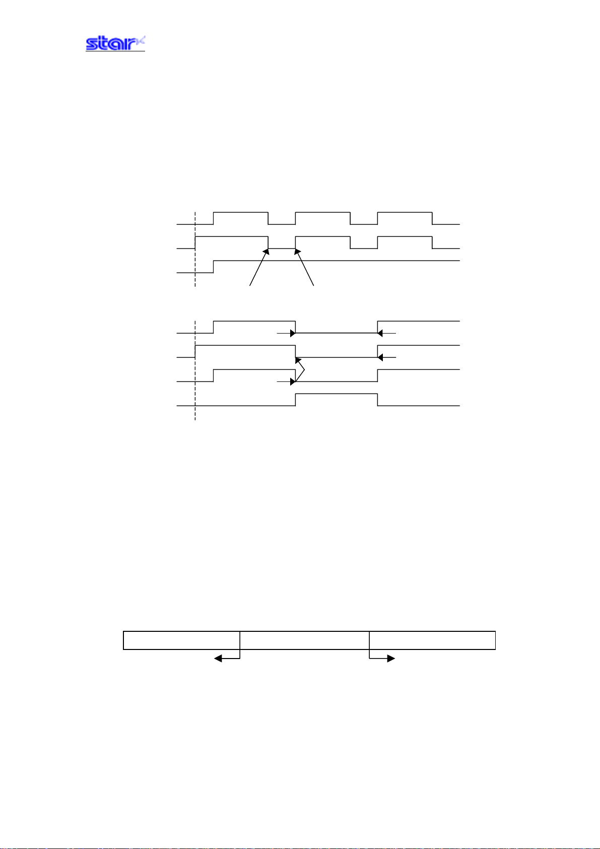
1) General description of operations in the DTR mode
This mode abides by the DIP switch settings. (Ex-factory settings)
This mode performs communication while handshaking with the DTR signals. In the operations to receive printer
data, this mode controls the DTR signals by confirming the BUSY signal. A SPACE indicates that the printer is ready
to receive data; conversely, a “mark” indicates that the printer cannot receive data.
<When ON-LINE>
RXD DATA DATA DATA
DTR
Printing
Power ON Buffer full Buffer empty
<When out of paper>
RXD OFF-LINE ON-LINE
DTR ON-LINE Recovery
Printing Out of paper
No paper signal
Power ON
If there is no printer error after turning ON the power, the DTR signal line is set to a SPACE. When the host computer
confirms that the DTR signal line is a SPACE, it sends the data text to the RXD signal line. The printer sets the DTR
signal line to a “Mark” after the empty area of the data buffer reaches a maximum of 256 bytes. When the host
computer confirms that the DTR signal line is a Mark, it stops the transmission of data text to the printer buffer, but at
this point as well, the printer is still capable of receiving data, up to the amount of empty space in the data buffer. If
the host computer ignores the DTR signal and transmits data, all data exceeding the amount of space in the data
buffer is simply discarded. The printer sets the DTR signal line to SPACE again when the amount of empty space in
the data buffer increased because of the printing and the data in the buffer is a maximum of 256 bytes.
2) Buffer full/Buffer full cancel in the DTR mode
Full Near Full Near Empty Empty
Buffer Empty area: 256 bytes Reception data: 256 bytes
DTR "Mark" DTR "SPACE"
DTR is set to mark at the point the empty area is a maximum of 256 bytes.
DTR is set to SPACE when the data in the buffer is a minimum of 256 bytes.
―――――――――――――――――――――――――――――――――――――――――― ――――――――――――――――――――――――――― ――――――――――――――――
STAR Line Mode Command Specifications 1-2
Page 8
3) General description of operations in the XON/XOFF mode
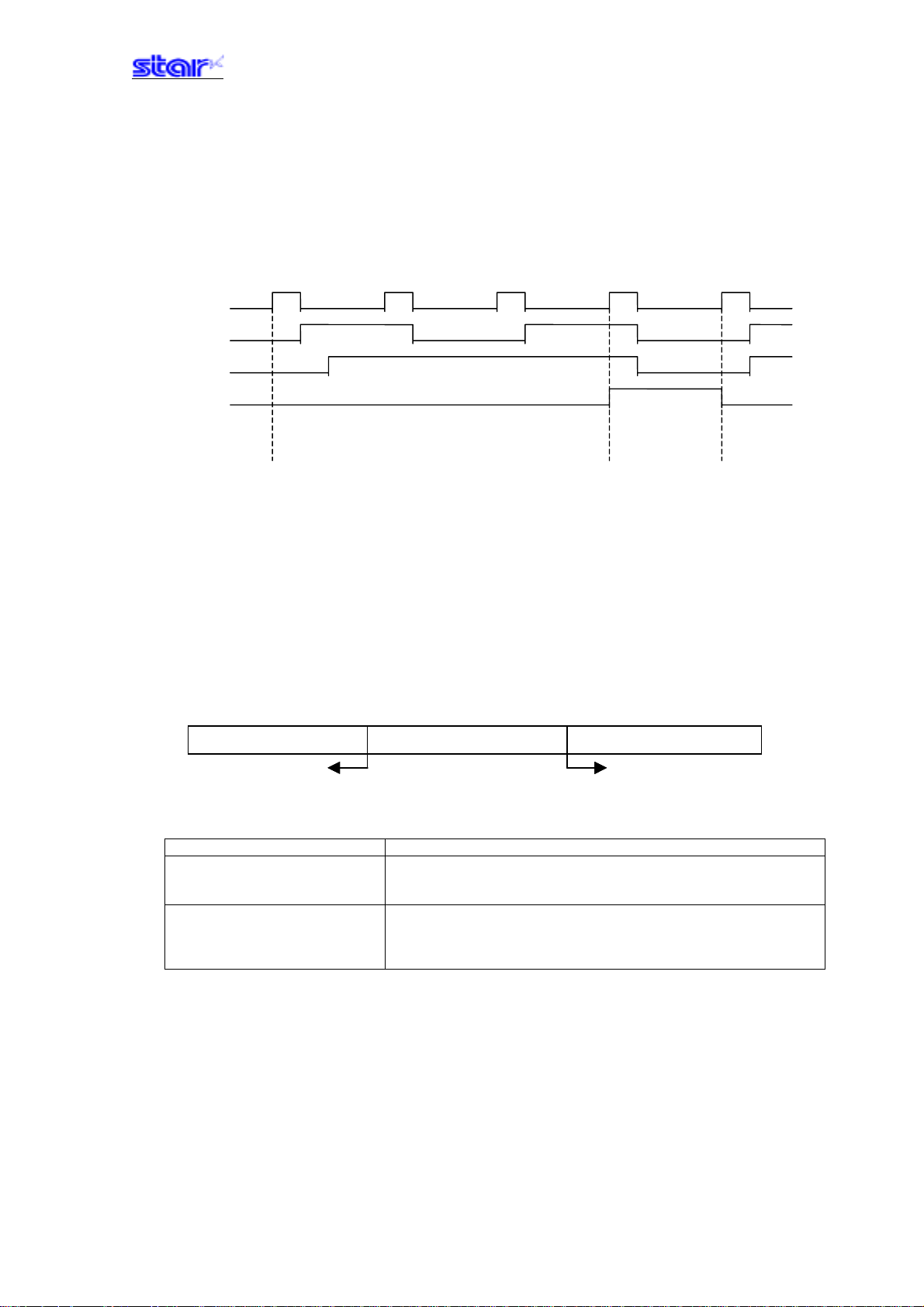
This mode is set when DIPSW #1 to #3 are turned OFF. This mode notifies the host of the XON (DC1) data when the
printer can receive data and the XOFF (DC3) data when the printer cannot receive data, using the TXD signals.
This functions so that XON outputs only 1 byte when the printer shifts from OFFLINE (printer busy) to ONLINE
(printer ready) and; XOFF outputs 1 byte when the printer shifts from ONLINE (printer ready) to OFFLINE (printer
busy) .
XON XOFF XON XOFF XON
TXD
RXD DATA DATA DATA
Printing
Out of
paper
signal
Power ON No paper ON-LINE Recovery
If there is no error after turning the power ON, XON (control code name: DC1; Hexadecimal name: 11H) is output by
the TXD signal line. After the host computer receives the XON, it sends the data text to the RXD signal line. XOFF
(CD3; 13H) is output when the empty space in the data buffer is a maximum of 256 bytes. The host computer stops
sending data text when it receives the XOFF, however, the printer is capable of receiving data at that time for the
amount of empty space in the data buffer. Data exceeding the amount of empty space is discarded. As the empty
space in the data buffer increases through printing, XON is output when the data in the buffer is a maximum of 256
bytes.
4) Buffer full/Buffer full cancel in the XON/XOFF mode
Full Near Full Near Empty Empty
Buffer Empty area: 256 bytes Reception data: 256 bytes
XOFF Output XON Output
Printer Setting Conditions Explanation of Operations
Memory switch B-4 = 0 XOFF outputs only 1 byte when the empty area is a
maximum of 256 bytes. XON outputs 1 byte when the
data in the buffer is a maximum of 256 bytes.
Memory switch B-4 = 1 XOFF output for every 1 byte of data received, when
the empty area is a maximum of 256 bytes. XON
output when the data in the buffer is a maximum of 256
bytes.
―――――――――――――――――――――――――――――――――――――――――― ――――――――――――――――――――――――――― ――――――――――――――――
STAR Line Mode Command Specifications 1-3
Page 9
1-2) Parallel Interfaces (Amphenol 36 pins)
1-2-1) Specifications (Conforming to IEEE1284)
Rating: Conforms to IEEE 1284
Mode: Compatibility Mode/Nibble Mode/Byte Mode
Data transfer speed: 1000 to 6000 CPS
Synch method: According to externally supplied strobe pulse
Handshake: According to ACK and BUSY signals
Logic level: Compatible to TTL
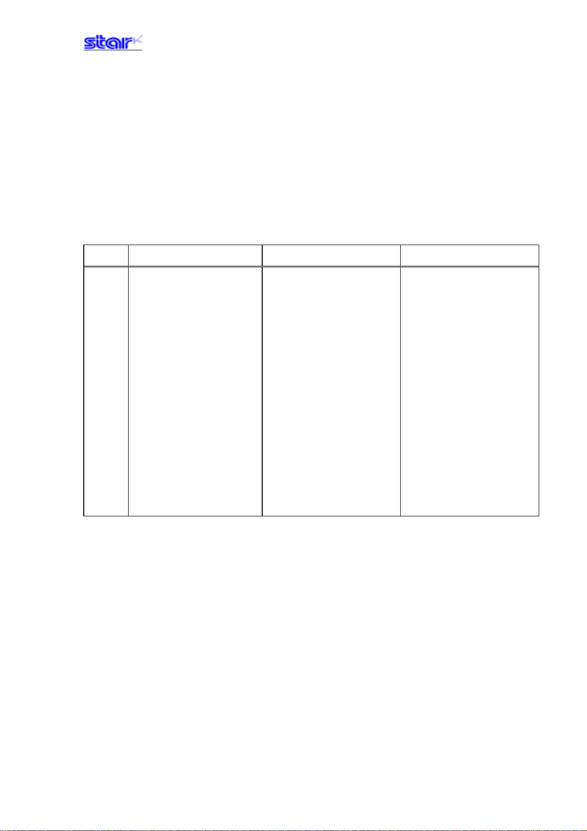
1-2-2) Signal array and explanations according to interface connector pin
<Signal Array and Functions>
Pin No. Compatibility Mode Signal
Nibble Mode Signal Name Byte Mode Signal Name
Name
1
2 to 9
10
11
12
13
14
15
16
17
18
19 to 30
31
32
33
34
35
36
nStrobe
Data0 to 7
nAck
Busy
PError
Select
N/C
N/C
Signal GND
Frame GND
+5V
Twisted Pair Return
nInit
nFault
External GND
N/C
N/C
nSelectIn
HostClk
Data0 to 7
PtrClk
PtrBusy/Data3,7
AckDataReq/Data2,6
Xflag/Data1,5
HostBusy
Signal GND
Frame GND
+5V
Twisted Pair Return
nInit
nDataAvail/Data0,4
-
-
1284Active
HostClk
Data0 to 7
PtrClk
PtrBusy
AckDataReq
Xflag
HostBusy
Signal GND
Frame GND
+5V
Twisted Pair Return
nInit
nDataAvail
-
-
1284Active
―――――――――――――――――――――――――――――――――――――――――― ――――――――――――――――――――――――――― ――――――――――――――――
STAR Line Mode Command Specifications 1-4
Page 10

1-2-3) Signal output timing
1) Compatibility mode
nStrobe
Data 0 to 7
nAck
Busy
2) Nibble Mode/Byte Mode
Conforms to IEEE 1284 standard
1-2-4) Status specification
See Appendix 2 for details.
T T T T= Max. 0.5 µs
Approx. 1 µs
―――――――――――――――――――――――――――――――――――――――――― ――――――――――――――――――――――――――― ――――――――――――――――
STAR Line Mode Command Specifications 1-5
Page 11

1-3) USB interface
Refer to the “USB Interface Specifications” documentation for details.
―――――――――――――――――――――――――――――――――――――――――― ――――――――――――――――――――――――――― ――――――――――――――――
STAR Line Mode Command Specifications 1-6
Page 12

1-4) Ethernet interface
Refer to the “Ethernet Interface Specifications” documentation for details.
―――――――――――――――――――――――――――――――――――――――――― ――――――――――――――――――――――――――― ――――――――――――――――
STAR Line Mode Command Specifications 1-7
Page 13
2. COMMAND FUNCTION LIST
• Standard Commands
Class Commands Name
Font style ESC GS t Specify code page
and character set ESC GS = Write blank code page data
ESC R Specify international character set
ESC / Specify/cancel slash zero
ESC SP Set ANK right space
ESC M Specify ANK 12 dot pitch
ESC P Specify ANK 5 dot pitch
ESC : Specify ANK 16 dot pitch
ESC g Specify ANK 14 dot pitch
Character ESC Set/cancel the double wide/high printing
expansion settings ESC W Set/cancel the double wide printing
ESC h Set/cancel the double high printing
SO Set double wide printing
DC4 Cancel double wide printing
ESC SO Set printing magnified double character height
ESC DC4 Cancel printing magnified character height
Print modes ESC E Select emphasized printing
ESC F Cancel emphasized printing
ESC - Select/cancels underling mode
ESC _ Select/cancels upperline mode
ESC 4 Select white/black inverted printing
ESC 5 Cancel white/black inverted printing
S Select upside-down printing
DC2 Cancel upside-down printing
Line spacing LF Line feed
CR Carriage return (same as line feed)
ESC a Feed paper n lines
ESC z Select line feed amount
ESC 0 Specify line spacing to 3 mm
ESC J n/4 mm line feed
ESC I n/8 mm line feed
―――――――――――――――――――――――――――――――――――――――――― ――――――――――――――――――――――――――― ――――――――――――――――
STAR Line Mode Command Specifications 2-1
Page 14
Class Commands Name
Page control FF Form feed
commands ESC C Set page length to n lines
ESC C 0 Set page length in 24 mm units
VT Feed paper to vertical tab position
ESC B Set vertical tab position
ESC N Set bottom margin to n lines
ESC O Cancel bottom margin
Horizontal ESC l Set left margin
direction ESC Q Set right margin
position HT Move print position to horizontal tab position
ESC D Set/cancel horizontal tab position
ESC GS A Move absolute position
ESC GS R Move relative position
ESC GS a Specify position alignment
Download ESC & Register/delete 12 x 24 dot font download characters
ESC % Set/cancel download characters
Bit image ESC K Standard density bit image
graphics ESC L High density bit image
ESC k Fine bit image
ESC X Fine bit image
Logos ESC FS q Register logo data
ESC FS p Print logo data
Bar code ESC b Print bar code
Cutter control ESC d Paper cutter instruction
External device ESC BEL Set pulse width for external device drive
Drive BEL External device 1 drive instruction
FS External device 1 drive instruction
SUB External device 2 drive instruction
EM External device 2 drive instruction
Print settings ESC RS d Set print density
ESC RS r Set printing speed
Status ESC RS a Set status transmission conditions
ESC ACK SOH Real-time printer status (ASB Status)
ENQ Real-time printer status (1)
EOT Real-time printer status (2)
―――――――――――――――――――――――――――――――――――――――――― ――――――――――――――――――――――――――― ――――――――――――――――
STAR Line Mode Command Specifications 2-2
Page 15
Class Commands Name
Chinese
characters
ESC p Set to JIS Chinese character mode
ESC q Cancel JIS Chinese character mode
ESC $ Set/cancel JIS Chinese character mode
ESC s Set two byte Chinese characters left/right spaces
ESC t Set 1 byte Chinese characters left/right spaces
ESC r Register Chinese download characters
Others CAN Cancel print data and initialize commands
ESC @ Command initialization
ESC GS # Set memory switch
ESC ? Reset printer
(*) Chinese character commands
• Chinese character control commands are ignored on printers not installed with Chinese character fonts (those
intended for overseas).
• All Chinese character control commands are ignored if the specification for the location of use is specified as
SBCS (single byte countries) by the memory switch.
• Raster related commands
Class Commands Name
Raster commands ESC * r R Initialize raster mode
ESC * r A Enter raster mode
ESC * r B Quit raster mode
ESC * r C Clear raster data
ESC * r D Drive drawer
ESC * r E Set EOT mode
ESC * r F Set FF mode
ESC * r P Set page length
ESC * r Q Set print quality
ESC * r m l Set left margin
ESC * r m r Set right margin
ESC * r T Set top margin
ESC * r K Set print color
b n1 n2 d1...dk Transfer raster data (auto line feed)
k n1 n2 d1...dk Transfer raster data
ESC FF NUL Execute form feed mode
ESC EOT NULL Execute EOT mode
―――――――――――――――――――――――――――――――――――――――――― ――――――――――――――――――――――――――― ――――――――――――――――
STAR Line Mode Command Specifications 2-3
Page 16
• Black mark related commands
Class Commands Name
Black mark ESC d Paper cut instruction
Related FF Form feed
Commands ESC C Set page length to n lines
ESC C 0 Set page length in 24 mm units
VT Feed paper to vertical tab position
ESC B Set vertical tab position
• USB I/F related commands
Class Commands Name
There are no commands for TSP600/700/800 and TUP900.
• 2 color printing related commands
Class Commands Name
2 color printing ESC RS c Specify printing color in 2 color printing mode
Related ESC RS C Select/cancel 2 color printing mode
Commands ESC 4 Specify white/black inversion and printing color red
ESC 5 Cancel white/black inversion and specify printing color black
ESC RS d Set print density
ESC RS r Set printing speed
ESC FS q Register logo
ESC FS p Print logo
• Presenter r el at e d co m m a nd s
Class Commands Name
Presenter ESC SYN 0 Execute presenter paper recovery
related ESC SYN 1 Set presenter automatic recovery function and recovery time
commands ESC SYN 3 Acquire presenter paper counter
ESC SYN 4 Initialize presenter paper counter
―――――――――――――――――――――――――――――――――――――――――― ――――――――――――――――――――――――――― ――――――――――――――――
STAR Line Mode Command Specifications 2-4
Page 17
3. COMMAND DETAILS
y
3-1) Explanation of Terms
• Reception buffer
The buffer for storing data (reception data) received from the host, as it is called the reception buffer.
Reception data is temporarily stored in the reception buffer, then processed sequentially.
• Line buffer
The buffer for storing image data for printing is called the line buffer.
• Line buffer full
The state in which the buffer has no more space available is called line buffer full. When the buffer is full in
standard mode, data in the line buffer is printed and a line feed is performed when new print data is processed.
This is the same as a Line Feed. When the line buffer is full in the page mode, the printer move the print position
to the head of the next line then starts with the new print data.
• Top of line
The top of line is a state that satisfies the following conditions.
- There is currently no print data in the line buffer.
- The position is not specified with the horizontal direction position command.
• Printable region
This is the maximum printable area with the printer’s specifications.
• Print region
This is the printing area specified by a command. (Print region ≤ printable region)
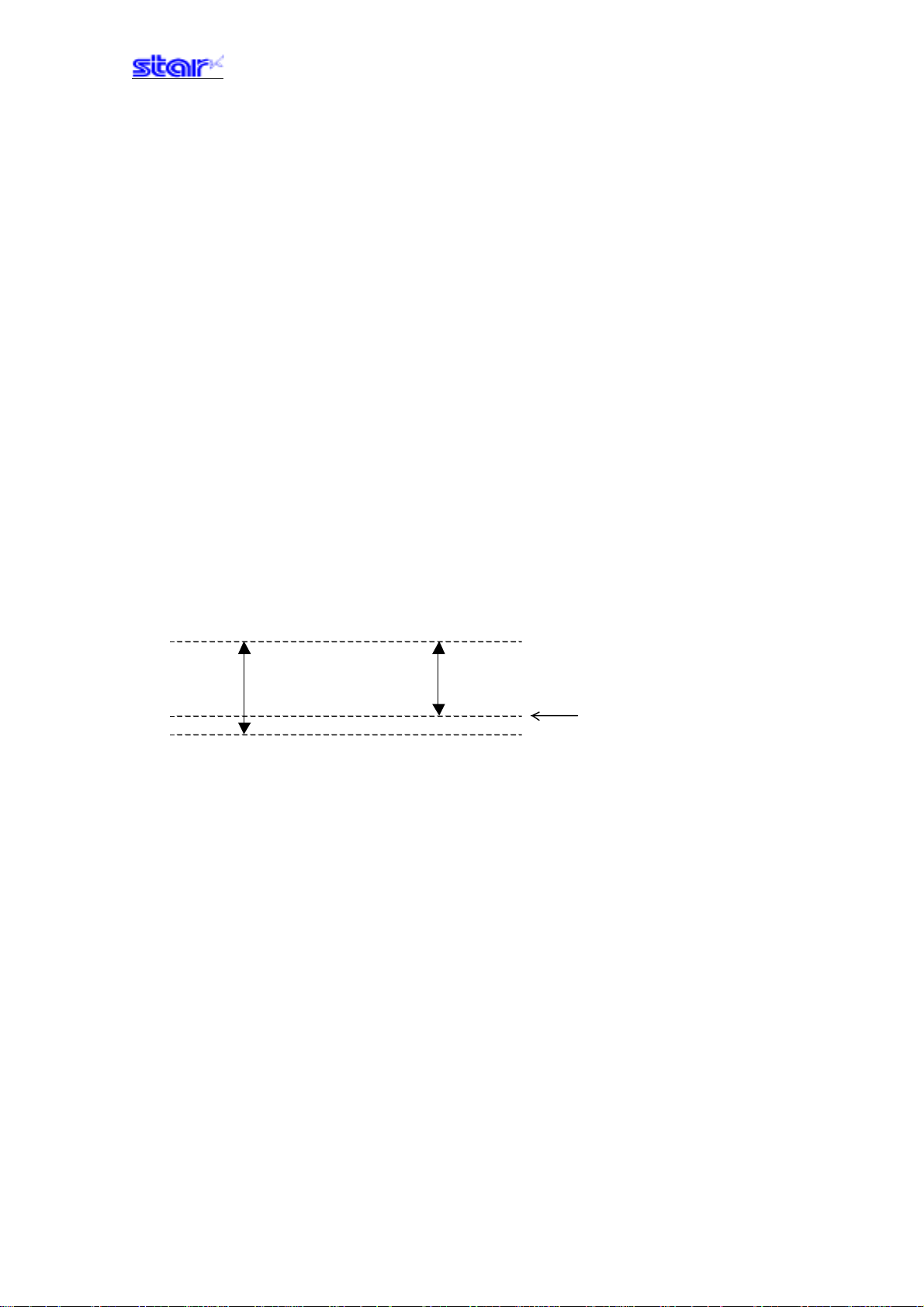
• ANK character base line
24 dots
A
20 dots
Base Line
―――――――――――――――――――――――――――――――――――――――――― ――――――――――――――――――――――――――― ――――――――――――――――
STAR Line Mode Command Specifications 3-1
Page 18

3-2) Exception processing
1) Undefined codes
Codes from <00>H to <1F>H are targeted. When codes not defined as commands in this region are received,
they are discarded.
(Ex.) If processing the data string of <30>H<31>H<03>H<32>H<0A>H<33>H, the printer will discard <03>H as
an undefined code.
2) Undefined commands
When data continuing the codes of ESC, FS, GS, DLE are codes not defined as commands, ESC, FS,GS and
subsequent codes are discarded.
(Ex.) If processing the data string of <30>H<1B>H<22>H<31>H<32>H, the printer will read and discard
<1B>H<22>H as an undefined command.
3) Settings outside of the defined area
Processing values outside of the defined area in commands accompanying arguments, those commands are
ignored and the preset values are unchanged. The processing of commands is terminated at the point values
outside of the defined region are processed in arguments having a plurality of commands. Data after that is
processed as normal data.
(Ex.) If processing the data string of <1B>H<52>H<15>H, the printer will discard the data string of
<1B>H<52>H<15>H because although <1B>H<52>H is defined as a commands (ESC R) , the argument
<15>H is outside of the definition. Therefore, the international character set that is already set
experiences no change.
―――――――――――――――――――――――――――――――――――――――――― ――――――――――――――――――――――――――― ――――――――――――――――
STAR Line Mode Command Specifications 3-2
Page 19
3-3) Standard Command Details
3-3-1) Font style and character set
ESC GS t n
[Name] Select code page
[Code] ASCII ESC GS t n
Hex. 1B 1D 74 n
Decimal 27 29 116 n
[Defined Region] 0≤n≤21
32≤n≤34
64≤n≤79
[Initial Value] Memory switch setting
When installed with Japanese language characters and DBCS setting: Fixed at n=2
[Function] Specifies code page
When installed with Japanese and Chinese language characters and DBCS setting, this
command is ignored.
n Code Page n Code Page
0 Normal* 32 Codepage 1252 (Windows Latin-1)
1 CodePage437 (USA,Std. Europe) 33 Codepage 1250 (Windows Latin-2)
2 Katakana 34 Codepage 1251 (Windows Cyrillic)
3 CodePage437 (USA,Std. Europe) 64 Codepage 3840 (IBM-Russian)
4 Codepage 858 (Multilingual) 65 Codepage 3841 (Gost)
5 Codepage 852 (Latin-2) 66 Codepage 3843 (Polish)
6 Codepage 860 (Portuguese) 67 Codepage 3844 (CS2)
7 Codepage 861 (Icelandic) 68 Codepage 3845 (Hungarian)
8 Codepage 863 (Canadian French) 69 Codepgae 3846 (Turkish)
9 Codepage 865 (Nordic) 70 Codepage 3847 (Brazil-ABNT)
10 Codepage 866 (Cyrillic Russian) 71 Codepage 3848 (Brazil-ABICOMP)
11 Codepage 855 (Cyrillic Bulgarian) 72 Codepage 1001 (Arabic)
12 Codepage 857 (Turkey) 73 Codepage 2001 (Lithuanian-KBL)
13 Codepage 862 (Israel (Hebrew) ) 74 Codepage 3001 (Estonian-1)
14 Codepage 864 (Arabic) 75 Codepage 3002 (Estonian-2)
15 Codepage 737 (Greek) 76 Codepage 3011 (Latvian-1)
16 Codepage 851 (Greek) 77 Codepage 3012 (Latvian-2)
17 Codepage 869 (Greek) 78 Codepage 3021 (Bulgarian)
18 Codepage 928 (Greek) 79 Codepage 3041 (Maltese)
19 Codepage 772 (Lithuanian) 255 User Setting Blank Code Page
20 Codepage 774 (Lithuanian)
21 Codepage 874 (Thai)
―――――――――――――――――――――――――――――――――――――――――― ――――――――――――――――――――――――――― ――――――――――――――――
STAR Line Mode Command Specifications 3-3
Page 20
ESC GS = n1 n2 da1 da2...dak db1 db2...dbk
[Name] Write blank code page data
[Code] ASCII ESC GS = n1 n2 da1 da2 ... dak db1 db2 … dbk
Hex. 1B 1D 3D n1 n2 da1 da2 ... dak db1 db2 … dbk
Decimal 27 29 61 n1 n2 da1 da2 ... dak db1 db2 … dbk
[Defined Area] n1= 0
n2 = 48
1≤(n1 + n2 x 256)
0≤da≤255 (Font-A data)
db = 0 (STAR mode is not installed with Font-B.)
k = (n1 + n2 x 256)
[Initial Value] - - [Function] A blank code page indicates a character code table where character codes from 80h to FFh
are all blank.
A blank code page can be selected using the ESC GS t n command n = 255.
The printer is reset when writing with this command is completed.
Font-A Data Format Vertical 24 dots x Horizontal 12 dots]
Da1 ●●●●●●●●Da2 ●●●●○○○○
Da3 ●●●●●●●●Da4 ●●●●○○○○
Da5 ●●●●●●●●Da6 ●●●●○○○○
Da7 ●●●●●●●●Da8 ●●●●○○○○
Da9 ●●●●●●●●Da10 ●●●●○○○○
Da11 ●●●●●●●●Da12 ●●●●○○○○
Da13 ●●●●●●●●Da14 ●●●●○○○○
Da15 ●●●●●●●●Da16 ●●●●○○○○
Da17 ●●●●●●●●Da18 ●●●●○○○○
Da19 ●●●●●●●●Da20 ●●●●○○○○
Da21 ●●●●●●●●Da22 ●●●●○○○○
Da23 ●●●●●●●●Da24 ●●●●○○○○
Da25 ●●●●●●●●Da26 ●●●●○○○○
Da27 ●●●●●●●●Da28 ●●●●○○○○
Da29 ●●●●●●●●Da30 ●●●●○○○○
Da31 ●●●●●●●●Da32 ●●●●○○○○
Da33 ●●●●●●●●Da34 ●●●●○○○○
Da35 ●●●●●●●●Da36 ●●●●○○○○
Da37 ●●●●●●●●Da38 ●●●●○○○○
Da39 ●●●●●●●●Da40 ●●●●○○○○
Da41 ●●●●●●●●Da42 ●●●●○○○○
Da43 ●●●●●●●●Da44 ●●●●○○○○
Da45 ●●●●●●●●Da46 ●●●●○○○○
Da47 ●●●●●●●●Da48 ●●●●○○○○
● = Data region/○=Zero data
MSB LSB MSB LSB
―――――――――――――――――――――――――――――――――――――――――― ――――――――――――――――――――――――――― ――――――――――――――――
STAR Line Mode Command Specifications 3-4
Page 21

ESC R n
[Name] Specify international character set
[Code] ASCII
Hex. 1B 52 n
Decimal 27 82 n
[Defined Area] 0≤n≤14
[Initial Value] Memory switch setting
[Function] Specifies international characters
n International Characters
0, 48 USA
1, 49 France
2, 50 Germany
3, 51 UK
4, 52 Denmark
5, 53 Sweden
6, 54 Italy
7, 55 Spain
8, 56 Japan
9, 57 Norway
10, 65 Denmark II
11, 66 Spain II
12, 67 Latin America
13, 68 Korea
14, 69 Ireland
64 Legal
ESC
n = 64
48≤n≤57 (”0”≤n≤”9”)
65≤n≤69 (”A”≤n≤”E”)
When installed with Japanese language characters and DBCS setting: Fixed at n=8
Rn
―――――――――――――――――――――――――――――――――――――――――― ――――――――――――――――――――――――――― ――――――――――――――――
STAR Line Mode Command Specifications 3-5
Page 22

ESC / n
[Name] Specify/cancel slash zero
[Code] ASCII ESC / n
Hex. 1B 2F n
Decimal 27 47 n
[Defined Area] n = 0, 1, 48, 49
[Initial Value] Memory switch setting
[Function] Specifies and cancels slash zeros.
n International Characters
0, 48 Cancels slash zero
1, 49 Specifies slash zero
―――――――――――――――――――――――――――――――――――――――――― ――――――――――――――――――――――――――― ――――――――――――――――
STAR Line Mode Command Specifications 3-6
Page 23

ESC SP n
[Name] Set ANK right space
[Code] ASCII ESC SP n
Hex. 1B 20 n
Decimal 27 32 n
[Defined Area] 0≤n≤15
48≤n≤57 (”0”≤n≤”9”)
65≤n≤70 (”A”≤n≤”F”)
[Initial Value] Memory switch setting
[Function] Specifies the right space for ANK 12 x 24 dot fonts in n dots.
Character spacing can be specified also with the following commands.
• Specify 12 dot pitch (ESC M)
• Specify 14 dot pitch (ESC g)
• Specify 15 dot pitch (ESC P)
• Specify 16 dot pitch (ESC :)
―――――――――――――――――――――――――――――――――――――――――― ――――――――――――――――――――――――――― ――――――――――――――――
STAR Line Mode Command Specifications 3-7
Page 24

ESC M
[Name] Specify 12 dot pitch
[Code] ASCII ESC M
Hex. 1B 4D
Decimal 27 77
[Defined Area] - - [Initial Value] Memory switch setting
[Function] Specifies rights space for the ANK 12 x 24 dot fonts to 0 dots.
ESC P
[Name] Specify 15 dot pitch
[Code] ASCII ESC P
Hex. 1B 50
Decimal 27 80
[Defined Area] - - [Initial Value] Memory switch setting
[Function] Specifies rights space for the ANK 12 x 24 dot fonts to 3 dots.
ESC :
[Name] Specify 16 dot pitch
[Code] ASCII ESC :
Hex. 1B 3A
Decimal 27 58
[Defined Area] - - [Initial Value] Memory switch setting
[Function] Specifies rights space for the ANK 12 x 24 dot fonts to 4 dots.
―――――――――――――――――――――――――――――――――――――――――― ――――――――――――――――――――――――――― ――――――――――――――――
STAR Line Mode Command Specifications 3-8
Page 25

ESC g
[Name] Specify 14 dot pitch
[Code] ASCII ESC g
Hex. 1B 67
Decimal 27 103
[Defined Area] - - [Initial Value] Memory switch setting
[Function] Specifies rights space for the ANK 12 x 24 dot fonts to 2 dots.
Specification A
This command is enabled only when the memory switch setting is set for DBCS (2 byte
countries). It is ignored when the memory switch setting is set for SBCS (1 byte countries).
Specification B
This command is enabled for both when the memory switch setting is set for either DBCS (2 byte
countries) or SBCS (1 byte countries).
Supplement:
Specification Type A and Specification Type B differ per model.
See the COMMAND LIST BY MODEL in Chapter 6. SPECIAL APPENDIX for your model.
―――――――――――――――――――――――――――――――――――――――――― ――――――――――――――――――――――――――― ――――――――――――――――
STAR Line Mode Command Specifications 3-9
Page 26

3-3-2) Character Expansion Settings
ESC i n1 n2
[Name] Set/cancel the double wide/high
[Code] ASCII ESC i n1 n2
Hex. 1B 69 n1 n2
Decimal 27 105 n1 n2
[Defined Area] 0≤n1≤5
48≤n1≤53 (”0”≤n1≤”5”)
0≤n2≤5
48≤n2≤53 (”0”≤n2≤”5”)
[Initial Value] n1 = 0 (Double high cancelled)
n2 = 0 (Double wide cancelled)
[Function] Specifies/cancels double high/wide for ANK characters and Chinese characters.
This command is ignored if either N1 or N2 is outside of the defined area.
n1 Expanded high
0, 48 Cancels expanded high
1, 49 Specifies 2x high expansion
2, 50 Specifies 3x high expansion
3, 51 Specifies 4x high expansion
4, 52 Specifies 5x high expansion
5, 53 Specifies 6x high expansion
n2 Expanded wide
0, 48 Cancels expanded wide
1, 49 Specifies 2x wide expansion
2, 50 Specifies 3x wide expansion
3, 51 Specifies 4x wide expansion
4, 52 Specifies 5x wide expansion
5, 53 Specifies 6x wide expansion
―――――――――――――――――――――――――――――――――――――――――― ――――――――――――――――――――――――――― ――――――――――――――――
STAR Line Mode Command Specifications 3-10
Page 27
ESC W n
[Name]
[Code] ASCII ESC W n
[Defined Area] 0≤n≤5
[Initial Value] n = 0 (Double wide cancelled)
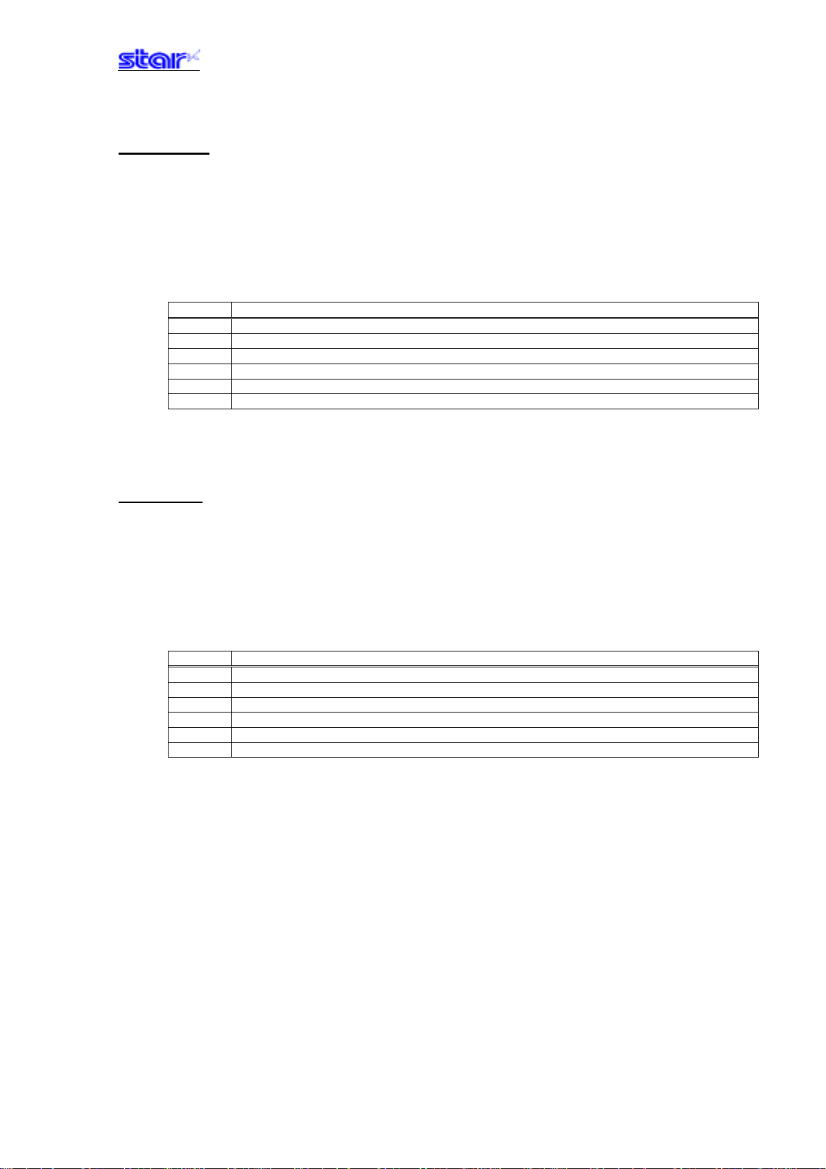
[Function] Specifies/cancels double wide for ANK characters and Chinese characters.
Specify/cancel expanded wide
Hex. 1B 57 n
Decimal 27 87 n
48≤n≤53 (”0”≤n≤”5”)
n Expanded wide
0, 48 Cancels expanded wide
1, 49 Specifies 2x wide expansion
2, 50 Specifies 3x wide expansion
3, 51 Specifies 4x wide expansion
4, 52 Specifies 5x wide expansion
5, 53 Specifies 6x wide expansion
ESC h n
[Name]
[Code] ASCII ESC h n
Specify/cancel expanded high
Hex. 1B 68 n
Decimal 27 104 n
[Defined Area] 0≤n≤5
48≤n≤53 (”0”≤n≤”5”)
[Initial Value] n = 0 (Double high cancelled)
[Function] Specifies/cancels double high for ANK characters and Chinese characters.
n Expanded high
0, 48 Cancels expanded high
1, 49 Specifies 2x expansion
2, 50 Specifies 3x expansion
3, 51 Specifies 4x expansion
4, 52 Specifies 5x expansion
5, 53 Specifies 6x expansion
―――――――――――――――――――――――――――――――――――――――――― ――――――――――――――――――――――――――― ――――――――――――――――
STAR Line Mode Command Specifications 3-11
Page 28

SO
[Name] Set double wide
[Code] ASCII SO
Hex. 0E
Decimal 14
[Defined Area] - - [Initial Value] Cancels 2x wide expansion
[Function] Specifies double wide for ANK characters and Chinese characters.
This command is equivalent to ESC W n (n = 1).
DC4
[Name] Cancel expanded wide
[Code] ASCII
Hex. 14
Decimal 20
[Defined Area] - - [Initial Value] - - [Function] Cancels expanded wide if the following commands specify expanded wide.
C4
• Double wide specifying command (SO)
• Set/cancel double wide (ESC W)
• Set/cancel double wide/high (ESC i)
This command is equivalent to ESC W n (n = 0).
―――――――――――――――――――――――――――――――――――――――――― ――――――――――――――――――――――――――― ――――――――――――――――
STAR Line Mode Command Specifications 3-12
Page 29

ESC SO
[Name] Set double high
[Code] ASCII ESC SO
Hex. 1B 0E
Decimal 27 14
[Defined Area] - - [Initial Value] Double high expansion cancelled.
[Function] Specifies double high for ANK characters and Chinese characters.
This command is equivalent to ESC h n (n = 1).
ESC DC4
[Name] Cancel expanded high
[Code] ASCII
Hex. 1B 14
Decimal 27 20
[Defined Area] - - [Initial Value] - - [Function] Cancels expanded high if the following commands specify expanded high.
ESC DC4
• Double high specifying command (ESC SO)
• Set/cancel the double high (ESC h)
• Set/cancel double wide/high (ESC i)
This command is equivalent to ESC h n (n = 0).
―――――――――――――――――――――――――――――――――――――――――― ――――――――――――――――――――――――――― ――――――――――――――――
STAR Line Mode Command Specifications 3-13
Page 30

3-3-3) Print mode
ESC E
[Name] Select emphasized printing
[Code] ASCII ESC E
Hex. 1B 45
Decimal 27 69
[Defined Area] - - [Initial Value] Emphasized printing selected
[Function] Specifies emphasized printing for ANK characters.
IBM block ignores emphasized printing.
ESC F
[Name] Cancel emphasized printing
[Code] ASCII ESC F
Hex. 1B 46
Decimal 27 70
[Defined Area] - - [Initial Value] Emphasized printing cancelled.
[Function] Cancels emphasized printing for ANK characters.
―――――――――――――――――――――――――――――――――――――――――― ――――――――――――――――――――――――――― ――――――――――――――――
STAR Line Mode Command Specifications 3-14
Page 31
ESC – n
[Name] Select/cancels underling mode
[Code] ASCII ESC - n
Hex. 1B 2D n
Decimal 27 45 n
[Defined Area] n = 0, 1, 48, 49
[Initial Value] n = 0 (Underline cancelled)
[Function] Specifies underlining (2 dots).
Underlines are composed of 2 dot lines.
Underlines are not applied to horizontal tabs and to specified horizontal direction positions.
Underlines are expanded if the character expansion is specified. (When double high expansion is
used, underlines are composed of 4 dots.)
Underlines are enabled for white/black inversion.
This command is enabled for ANK characters and Chinese characters.
IBM block ignores underlines.
n Underline
0, 48 Cancels underline
1, 49 Specifies underline
ESC _ n
[Name]
[Code] ASCII ESC _ n
Specify/cancel upperline
Hex. 1B 5F n
Decimal 27 95 n
[Defined Area] n = 0, 1, 48, 49
[Initial Value] n = 0 (Upperline cancelled)
[Function] Specifies upperlining (2 dots).
Upperlines are composed of 2 dot lines.
Upperlines are not applied to horizontal tabs and to specified horizontal direction positions.
Upperlines are expanded if the character expansion is specified. (When double high expansion is
used, upperlines are composed of 4 dots.)
Upperlines are enabled for white/black inversion.
This command is enabled for ANK characters and Chinese characters.
IBM block ignores upperlines.
n Upperline
0, 48 Cancels upperline
1, 49 Specifies upperline
―――――――――――――――――――――――――――――――――――――――――― ――――――――――――――――――――――――――― ――――――――――――――――
STAR Line Mode Command Specifications 3-15
Page 32

ESC 4
[Name] Select white/black inverted printing
[Code] ASCII ESC 4
Hex. 1B 34
Decimal 27 52
[Defined Area] - - [Initial Value] White/black inversion cancelled
[Function] Specifies white/black inversion for ANK characters and Chinese characters.
IBM block ignores white/black inversion.
ESC 5
[Name] Cancel white/black inversion
[Code] ASCII ESC 5
Hex. 1B 35
Decimal 27 53
[Defined Area] - - [Initial Value] White/black inversion cancelled
[Function] Cancels white/black inversion for ANK characters and Chinese characters.
―――――――――――――――――――――――――――――――――――――――――― ――――――――――――――――――――――――――― ――――――――――――――――
STAR Line Mode Command Specifications 3-16
Page 33

SI
[Name] Select upside-down printing
[Code] ASCII SI
Hex. 0F
Decimal 15
[Defined Area] - - [Initial Value] Upside-down cancelled
[Function] Specifies upside-down printing
This command is enabled only when at the top of the line.
Upside down and right-side up characters cannot both exist in the same line.
This command is enabled for following.
• ANK characters
• Chinese characters
• Bit images
• Logos
• Bar codes
DC2
[Name] Cancel upside-down printing
[Code] ASCII
Hex. 12
Decimal 18
C2
[Defined Area] - - [Initial Value] Upside-down printing cancelled
[Function] Cancels upside-down printing
This command is enabled only when at the top of the line.
―――――――――――――――――――――――――――――――――――――――――― ――――――――――――――――――――――――――― ――――――――――――――――
STAR Line Mode Command Specifications 3-17
Page 34

3-3-4) Line spacing
LF
[Name] Line feed
[Code] ASCII LF
Hex. 0A
Decimal 10
[Defined Area] - - [Initial Value] - - [Function] Feeds the currently specified amount of paper.
If print data exists in the line buffer, it prints that data.
The initial value for the amount of paper is set according to the memory switch settings.
CR
[Name] Carriage return (line feed)
[Code] ASCII CR
Hex. 0D
Decimal 13
[Defined Area] - - [Initial Value] - - [Function] When the CR code is enabled, the CR code functions in the same way as the LF code.
If the CR code is disabled, it ignores 1 byte.
Enabling and disabling the CR code is done using the memory switch settings.
ESC a n
[Name] Feed paper n lines
[Code] ASCII ESC a n
Hex. 1B 61 n
Decimal 27 97 n
[Defined Area] 1≤n≤127
[Initial Value] - - [Function] Executes a paper feed for (the currently specified line feed amount x n). If print data exists in the
line buffer, it prints that data.
The initial value for the amount of paper is set according to the memory switch settings.
―――――――――――――――――――――――――――――――――――――――――― ――――――――――――――――――――――――――― ――――――――――――――――
STAR Line Mode Command Specifications 3-18
Page 35

ESC z n
[Name] Select line feed amount
[Code] ASCII ESC z n
Hex. 1B 7A n
Decimal 27 122 n
[Defined Area] n = 1, 49
[Initial Value] Memory switch setting
[Function] Specifies the line feed amount.
n Line feed amount
1, 49 Specifies 4 mm line feed amount
ESC 0
[Name] Specify line spacing to 3 mm
[Code] ASCII ESC 0
Hex. 1B 30
Decimal 27 48
[Defined Area] - - [Initial Value] Memory switch setting
[Function] Specifies the line feed amount to 3 mm.
―――――――――――――――――――――――――――――――――――――――――― ――――――――――――――――――――――――――― ――――――――――――――――
STAR Line Mode Command Specifications 3-19
Page 36

ESC J n
[Name] n/4 mm line feed
[Code] ASCII ESC J n
Hex. 1B 4A n
Decimal 27 74 n
[Defined Area] 1≤n≤255
[Initial Value] - - [Function] Executes a n/4mm paper feed.
If print data exists in the line buffer, it prints that data.
Using this command will intermittently feed paper, therefore, it is normally recommended that this
command not be used.
ESC I n
[Name] n/8mm line feed
[Code] ASCII ESC I n
Hex. 1B 49 n
Decimal 27 73 n
[Defined Area] 1≤n≤255
[Initial Value] - - [Function] Executes a n/8mm paper feed.
If print data exists in the line buffer, it prints that data.
Using this command will intermittently feed paper, therefore, it is normally recommended that this
command not be used.
―――――――――――――――――――――――――――――――――――――――――― ――――――――――――――――――――――――――― ――――――――――――――――
STAR Line Mode Command Specifications 3-20
Page 37

3-3-5) Page control commands
FF
[Name] Form feed
[Code] ASCII FF
Hex. 0C
Decimal 12
[Defined Area] - - [Initial Value] - - -
[Function] Executes a form feed.
If the current position is at the top of the page, it form feeds to the top of the next page.
If there is data existing in the line buffer when executing a form feed, it prints that data, then
executes the form feed.
However, by printing data remaining in the buffer, and moving to the top of the next page, a form
feed is considered to have been executed, so form feed is not performed.
ESC C n
[Name] Set page length to n lines
[Code] ASCII ESC C n
Hex. 1B 43 n
Decimal 27 67 n
[Defined Area] 1≤n≤127
[Initial Value] (Form feed amount initial value x 42)
[Function] The position whereat this command is processed is considered the top of the page and sets the
page length to (current form feed amount x n).
This command cancels the bottom margin setting when setting page length.
The page length set using this command is unaffected by changing the form feed amount later.
Moving to the top of the page is performed using the following commands.
• Form feed command (FF): Executes a form feed.
• Cutter command (ESC d n): Sets cutter position at top of page.
• Raster command (ESC * r B): Sets top of page when quitting raster mode.
• Error cancel operations: Sets position when quitting error cancellation operations
at top of page.
―――――――――――――――――――――――――――――――――――――――――― ――――――――――――――――――――――――――― ――――――――――――――――
STAR Line Mode Command Specifications 3-21
Page 38

ESC C 0 n
[Name] Set page length to n x 24 mm units
[Code] ASCII ESC C 0 n
Hex. 1B 43 00 n
Decimal 27 67 0 n
[Defined Area] 1≤n≤22
[Initial Value] (Form feed amount initial value x 42)
[Function] The position whereat this command is processed is considered the top of the page and sets the
page length to (n x 24 mm).
This command cancels the bottom margin setting when setting page length.
The page length set using this command is unaffected by changing the form feed amount later.
Moving to the top of the page is performed using the following commands.
• Form feed command (FF): Executes a form feed.
• Cutter command (ESC d n): Sets cutter position at top of page.
• Raster command (ESC * r B): Sets top of page when quitting raster mode.
• Error cancel operations: Sets position when quitting error cancellation operations
at top of page.
―――――――――――――――――――――――――――――――――――――――――― ――――――――――――――――――――――――――― ――――――――――――――――
STAR Line Mode Command Specifications 3-22
Page 39

VT
[Name] Feed paper to vertical tab position
[Code] ASCII VT
Hex. 0B
Decimal 11
[Defined Area] - - [Initial Value] - - [Function] Feeds paper to the next vertical tab position.
This command is ignored if there are no tabs set.
If a vertical tab is set, and the current position is the same as the vertical tab position, or if it is
below that position, it feeds paper to the top of the next page.
If data exists in the line buffer when feeing paper to the vertical tab position, it executes the
paper feed to the vertical tab position after printing that data. However, if moved to the vertical
tab position by printing data remaining in the buffer, the move to the vertical tab position is
considered to have been executed, so a move to the next vertical tab position is not performed.
There is no initial value for the vertical tab.
―――――――――――――――――――――――――――――――――――――――――― ――――――――――――――――――――――――――― ――――――――――――――――
STAR Line Mode Command Specifications 3-23
Page 40

ESC B n1 n2…nk NUL
[Name] Set vertical tab position
[Code] ASCII ESC B n1 n2 ... nk
Hex. 1B 42 n1 n2 ... nk 00
Decimal 27 66 n1 n2 ... nk 0
[Defined Area] 1≤n≤255
0≤k≤16
[Initial Value] - - [Function] Sets the vertical tab to the (current form feed amount x n) position.
All other vertical tabs set before setting the vertical tab using this command are cancelled
A maximum of 16 vertical tabs can be set. However, the tab position must satisfy the condition of
1≤n1≤n2... ≤nk. When receiving such illegal codes, tabs up to the illegal code are set, but those
after the illegal code are discarded up to the NUL code so illegal code tab are not set.
The vertical tab set using this command is unaffected by changing the form feed amount later.
Vertical tabs set using the ESC B NUL command are cleared.
There is no initial value for the vertical tab.
UL
ESC B NUL
[Name] Clear vertical tab position
[Code] ASCII ESC B NUL
Hex. 1B 42 00
Decimal 27 66 0
[Defined Area] - - [Initial Value] - - [Function] Clears the currently set vertical tab.
―――――――――――――――――――――――――――――――――――――――――― ――――――――――――――――――――――――――― ――――――――――――――――
STAR Line Mode Command Specifications 3-24
Page 41

3-3-6) Horizontal direction printing position
ESC l n
[Name] Set left margin
[Code] ASCII ESC l n
Hex. 1B 6C n
Decimal 27 108 n
[Defined Area] 0≤n≤255
[Initial Value] n = 0
[Function] Uses the left edge as a standard to set the left margin as (current ANK character pitch x n).
Character pitch includes the space between characters and expansion settings are enabled.
The left margin set using this command is unaffected by changing the character pitch.
This command is ignored if settings are for a printing region less than 36 mm.
Specification A
Setting this command partway will take affect from the next line.
Specification B
This command is enabled only when at the top of the line.
Supplement:
Specification Type A and Specification Type B differ per model.
See the COMMAND LIST BY MODEL in Chapter 6. SPECIAL APPENDIX for your model.
―――――――――――――――――――――――――――――――――――――――――― ――――――――――――――――――――――――――― ――――――――――――――――
STAR Line Mode Command Specifications 3-25
Page 42
ESC Q n
[Name] Set right margin
[Code] ASCII ESC Q n
Hex. 1B 51 n
Decimal 27 81 n
[Defined Area] 0≤n≤255
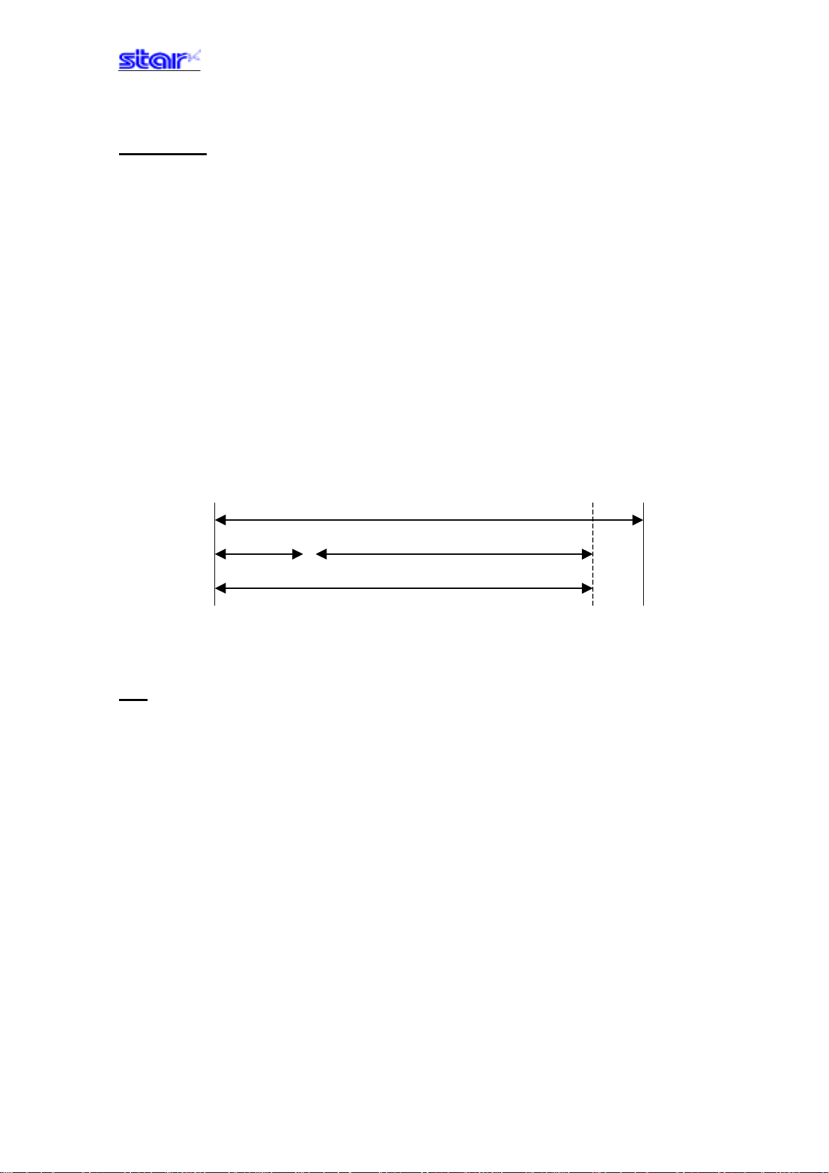
[Initial Value] - - [Function] Uses the left edge as a standard to set the print region as (current ANK character pitch x n).
Character pitch includes the space between characters and expansion settings are enabled.
The right margin set using this command is unaffected by changing the character pitch.
This command is ignored if settings are for a printing region less than 36 mm.
Specification A
Setting this command partway will take affect from the next line.
Specification B
This command is enabled only when at the top of the line.
Supplement:
Specification Type A and Specification Type B differ per model.
See the COMMAND LIST BY MODEL in Chapter 6. SPECIAL APPENDIX for your model.
Printable Region
Left Margin Print Region
Right Margin
HT
[Name] Move horizontal tab
[Code] ASCII HT
Hex. 09
Decimal 9
[Defined Area] - - [Initial Value] - - [Function] Move print position to next horizontal tab position.
This command is ignored with under the following conditions.
• When there is no horizontal tab set.
• When the current position is the same as the furthest right horizontal tab position or to the right
of it.
There is no initial value for the horizontal tab.
―――――――――――――――――――――――――――――――――――――――――― ――――――――――――――――――――――――――― ――――――――――――――――
STAR Line Mode Command Specifications 3-26
Page 43

ESC D n1 n2…nk NUL
[Name] Set horizontal tab
[Code] ASCII ESC D n1 n2 ... nk
Hex. 1B 44 n1 n2 ... nk 00
Decimal 27 68 n1 n2 ... nk 0
[Defined Area] 1≤n≤255
0≤k≤16
[Initial Value] - - [Function] Uses the left edge as a standard to set the horizontal tab to the position of (current ANK
character pitch x n).
The horizontal tab reference point is the right edge of the paper, regardless of the left margin.
ANK character pitch includes the right space and expansion settings are enabled.
All other horizontal tabs set before setting the horizontal tab using this command are cancelled
A maximum of 16 horizontal tabs can be set.
However, the tab position must satisfy the following conditions.
If the following conditions are not met, data up to the NUL code is discarded.
Normal tabs that meet the conditions below are set and tabs after errors occur are not set.
• 1≤n1≤n2... ≤nk
• nk ≤ Printable region
The horizontal tab set using this command is unaffected by changing the character pitch.
Horizontal tabs set using the ESC D NUL command are cleared.
There is no initial value for the horizontal tab.
UL
ESC D NUL
[Name] Clear horizontal tab
[Code] ASCII ESC D
Hex. 1B 44 00
Decimal 27 68 0
[Defined Area] - - [Initial Value] - - [Function] Clears the currently set horizontal tab.
UL
―――――――――――――――――――――――――――――――――――――――――― ――――――――――――――――――――――――――― ――――――――――――――――
STAR Line Mode Command Specifications 3-27
Page 44

ESC GS A n1 n2
[Name] Move absolute position
[Code] ASCII ESC GS A n1 n2
Hex. 1B 1D 41 n1 n2
Decimal 272965n1n2
[Defined Area] 0≤n1≤255
0≤n2≤255
[Initial Value] - - [Function] Moves the printing position from the left margin to the (n1 + n2 x 256) position.
This command is ignored if the print region is exceeded.
ESC GS R n1 n2
[Name] Move relative position
[Code] ASCII ESC GS R n1 n2
Hex. 1B 1D 52 n1 n2
Decimal 272982n1n2
[Defined Area] 0≤n1≤255
0≤n2≤255
[Initial Value] - - [Function] Moves the printing position from the current position to the (n1 + n2 x 256) position.
This command is ignored if the print region is exceeded.
When (n1 + n2 x 256)
When (n1 + n2 x 256) < 32768, it moves (n1 + n2 x 256)} dots in the right direction.
32768, it moves {65536 – (n1 + n2 x 256)} dots in the left direction.
―――――――――――――――――――――――――――――――――――――――――― ――――――――――――――――――――――――――― ――――――――――――――――
STAR Line Mode Command Specifications 3-28
Page 45
ESC GS a n
[Name] Specify position alignment
[Code] ASCII ESC GS a n
Hex. 1B 1D 61 n
Decimal 27 29 97 n
[Defined Area] 0≤n≤2
48≤n≤50 (”0”≤n≤”2”)
[Initial Value] n = 0
[Function] Specifies the alignment position in the printing region that has been set.
n Position alignment
0, 48 Left alignment
1, 49 Center alignment
2, 50 Right alignment
―――――――――――――――――――――――――――――――――――――――――― ――――――――――――――――――――――――――― ――――――――――――――――
STAR Line Mode Command Specifications 3-29
Page 46
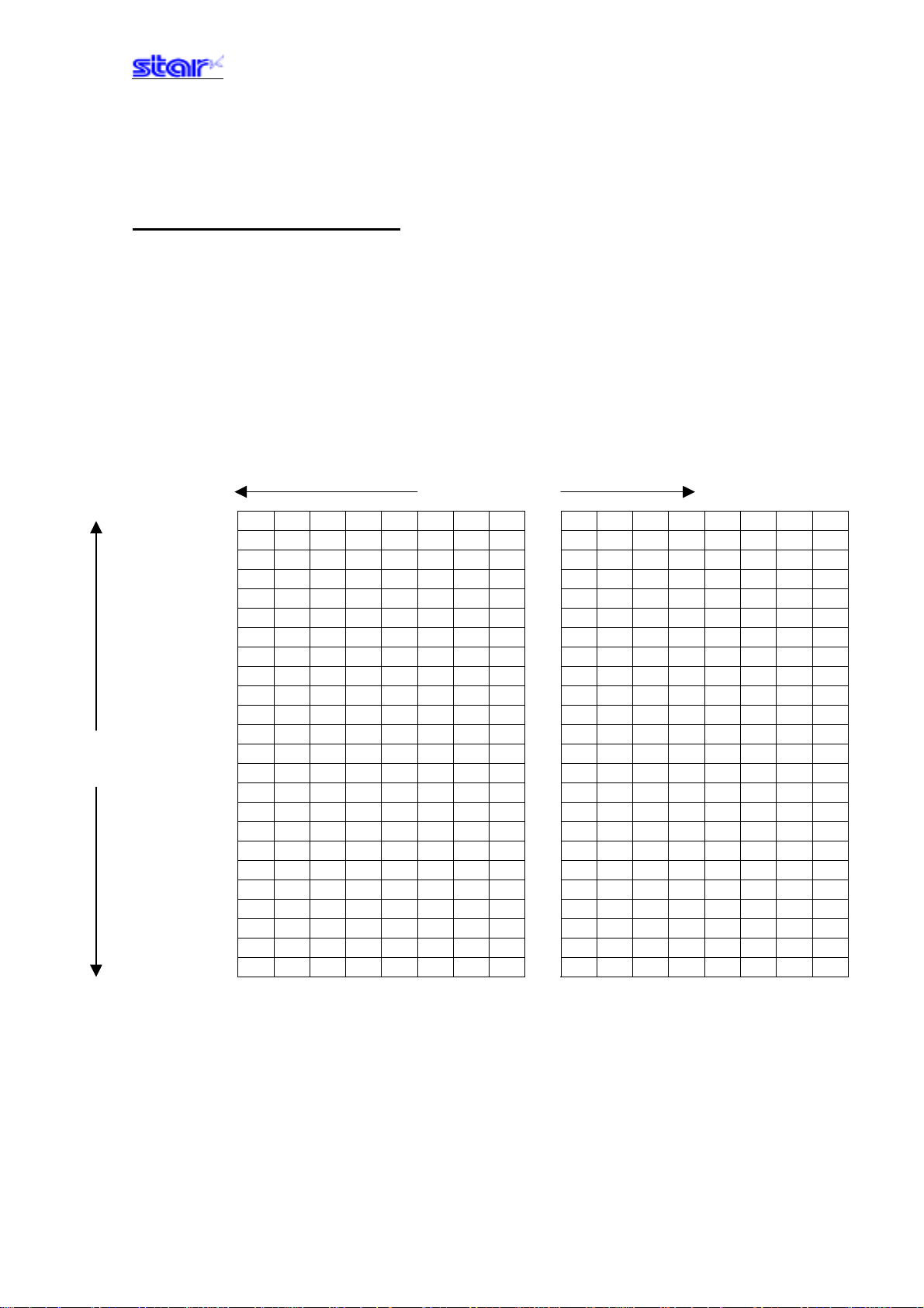
Vertica
l
24 Dots
3-3-7) Download
ESC & c1 c2 n d1…d48
[Name] Register 12 x 24 dot font download characters
[Code] ASCII ESC & c1 c2 n d1 ... d48
Hex. 1B 26 c1 c2 n d1 ... d48
Decimal 27 38 c1 c2 n d1 ... d48
[Defined Area] c1 = 1, 49
c2 = 1, 49
32≤n≤127
0≤d≤255
[Initial Value] - - [Function] Registers 12 x 24 dot font download characters to the nth address.
Download characters can be registered to <20>H to <7F>H.
If one has been already registered to an address, it is overwritten.
When parameters c1 and c2 and n are outside of the defined area, subsequent data is handled
as normal data.
d1 ●●●●●●●●d2 ●●●●○○○○
d3 ●●●●●●●●d4 ●●●●○○○○
d5 ●●●●●●●●d6 ●●●●○○○○
d7 ●●●●●●●●d8 ●●●●○○○○
d9 ●●●●●●●●d10 ●●●●○○○○
d11 ●●●●●●●●d12 ●●●●○○○○
d13 ●●●●●●●●d14 ●●●●○○○○
d15 ●●●●●●●●d16 ●●●●○○○○
d17 ●●●●●●●●d18 ●●●●○○○○
d19 ●●●●●●●●d20 ●●●●○○○○
d21 ●●●●●●●●d22 ●●●●○○○○
d23 ●●●●●●●●d24 ●●●●○○○○
d25 ●●●●●●●●d26 ●●●●○○○○
d27 ●●●●●●●●d28 ●●●●○○○○
d29 ●●●●●●●●d30 ●●●●○○○○
d31 ●●●●●●●●d32 ●●●●○○○○
d33 ●●●●●●●●d34 ●●●●○○○○
d35 ●●●●●●●●d36 ●●●●○○○○
d37 ●●●●●●●●d38 ●●●●○○○○
d39 ●●●●●●●●d40 ●●●●○○○○
d41 ●●●●●●●●d42 ●●●●○○○○
d43 ●●●●●●●●d44 ●●●●○○○○
d45 ●●●●●●●●d46 ●●●●○○○○
d47 ●●●●●●●●d48 ●●●●○○○○
bit7 bit6 bit5 bit4 bit3 bit2 bit1 Bit0 bit7 bit6 bit5 bit4 bit3 bit2 bit1 bit0
Horizontal 12
Dots
●: Font data ○: Invalid data
―――――――――――――――――――――――――――――――――――――――――― ――――――――――――――――――――――――――― ――――――――――――――――
STAR Line Mode Command Specifications 3-30
Page 47
ESC & c1 c2 n
[Name] Delete 12 x 24 dot font download characters
[Code] ASCII ESC & c1 c2 n
Hex. 1B 26 c1 c2 n
Decimal 27 38 c1 c2 n
[Defined Area] c1 = 1, 49
c2 = 0, 48
32≤n≤127
[Initial Value] - - [Function] Deletes 12 x 24 dot font download characters registered to the nth address.
ESC % n
[Name] Specifies/cancels ANK download characters
[Code] ASCII ESC % n
Hex. 1B 25 n
Decimal 27 37 n
[Defined Area] n=0, 1, 48, 49
[Initial Value] ANK download characters cancelled
[Function] Specifies/cancels ANK download characters
n Download characters
0, 48 Cancels ANK download characters
1, 49 Specifies ANK download characters
<Print example of ANK download characters>
1. ANK download character register (ESC & c1 c2 n d1…d48)
2. Specify ANK download characters (ESC % n (n = 1))
3. Prints ANK download characters
―――――――――――――――――――――――――――――――――――――――――― ――――――――――――――――――――――――――― ――――――――――――――――
STAR Line Mode Command Specifications 3-31
Page 48
3-3-8) Bit image graphics
ESC K n1 n2 d1...dk
[Name] Standard density bit image
[Code] ASCII ESC K n1 n2 d1 ... dk
Hex. 1B 4B n1 n2 d1 ... dk
Decimal 2775n1n2d1 ...dk
[Defined Area] 1 ≤ {(n1 + n2 x 256) x 3} ≤ printable region
k = (n1 + n2 x 256)
0≤d≤255
[Initial Value] - - [Function] Prints bit images using 3 dots wide and 3 dots high per 1 dot of input data.
The following shows the data processing in this command.
• When {(n1 + n2 x 256) x 3} exceeds the printable region, data after d1 is handled as normal
data.
• When {(n1 + n2 x 256) x 3} exceeds the printable region that is currently set, only the data in
the printing region is printed.
At this time, all data for the print region is discarded.
• If the current position already exceeds the print region, this command discards all data.
b7 b6 b5 b4 b3 b2 b1 b0
• • •
• • •
• • •
• • •
• • •
• • •
• • •
• • •
• • •
• • •
• • •
• • •
• • •
• • •
• • •
• • •
• • •
• • •
• • •
• • •
• • •
• • •
• • •
• • •
―――――――――――――――――――――――――――――――――――――――――― ――――――――――――――――――――――――――― ――――――――――――――――
STAR Line Mode Command Specifications 3-32
Page 49
ESC L n1 n2 d1...dk
[Name] Standard density bit image
[Code] ASCII ESC L n1 n2 d1 ... dk
Hex. 1B 4C n1 n2 d1 ... dk
Decimal 2776n1n2d1 ...dk
[Defined Area] 1 ≤ (n1 + n2 x 256) ≤ printable region
k = (n1 + n2 x 256)
0≤d≤255
[Initial Value] - - [Function] Prints bit images using 1 dots wide and 3 dots high per 1 dot of input data.
The following shows the data processing in this command.
• When (n1 + n2 x 256) exceeds the printable region, data after d1 is handled as normal data.
• When (n1 + n2 x 256) exceeds the printable region that is currently set, only the data in the
printing region is printed.
At this time, all data for the print region is discarded.
• If the current position already exceeds the print region, this command discards all data.
•
•
•
•
•
•
•
•
•
•
•
•
•
•
•
•
•
•
•
•
•
•
•
•
b7 b6 b5 b4
b3 b2 b1 b0
―――――――――――――――――――――――――――――――――――――――――― ――――――――――――――――――――――――――― ――――――――――――――――
STAR Line Mode Command Specifications 3-33
Page 50
ESC k n1 n2 d1...dk
[Name] Fine density bit image
[Code] ASCII ESC k n1 n2 d1 ... dk
Hex. 1B 6B n1 n2 d1 ... dk
Decimal 27 107 n1 n2 d1 ... dk
[Defined Area] n2 = 0
1 ≤ {(n1 + n2 x 256) x 8} ≤ printable region
k = {(n1 + n2 x 256) x 24}
0≤d≤255
[Initial Value] - - [Function] Prints bit images using 1 dots wide and 1 dots high per 1 dot of input data.
The following shows the data processing in this command.
• When {(n1 + n2 x 256) x 8} exceeds the printable region, data after d1 is handled as normal
data.
• When {(n1 + n2 x 256) x 8} exceeds the printable region that is currently set, only the data in
the printing region is printed.
At this time, all data for the print region is discarded.
• If the current position already exceeds the print region, this command discards all data.
d1 d2 • • • • • • • dn
dn+1 dn+2 • • • • • • • d2n
d2n+1 d2n+2 • • • • • • • d3n
d3n+1 d3n+2 • • • • • • • d4n
d4n+1 d4n+2 • • • • • • • d5n
d5n+1 d5n+2 • • • • • • • d6n
d6n+1 d6n+2 • • • • • • • d7n
d7n+1 d7n+2 • • • • • • • d8n
d8n+1 d8n+2 • • • • • • • d9n
d9n+1 d9n+2 • • • • • • • d10n
d10n+1 d10n+2 • • • • • • • d11n
d11n+1 d11n+2 • • • • • • • d12n
d12n+1 d12n+2 • • • • • • • d13n
d13n+1 d13n+2 • • • • • • • d14n
d14n+1 d14n+2 • • • • • • • d15n
d15n+1 d15n+2 • • • • • • • d16n
d16n+1 d16n+2 • • • • • • • d17n
d17n+1 d17n+2 • • • • • • • d18n
d18n+1 d18n+2 • • • • • • • d19n
d19n+1 d19n+2 • • • • • • • d20n
d20n+1 d20n+2 • • • • • • • d21n
d21n+1 d21n+2 • • • • • • • d22n
d22n+1 d22n+2 • • • • • • • d23n
d23n+1 d23n+2 • • • • • • • d24n
bit7 bit6 bit5 bit4 bit3 bit2 bit1 bit0
―――――――――――――――――――――――――――――――――――――――――― ――――――――――――――――――――――――――― ――――――――――――――――
STAR Line Mode Command Specifications 3-34
Page 51
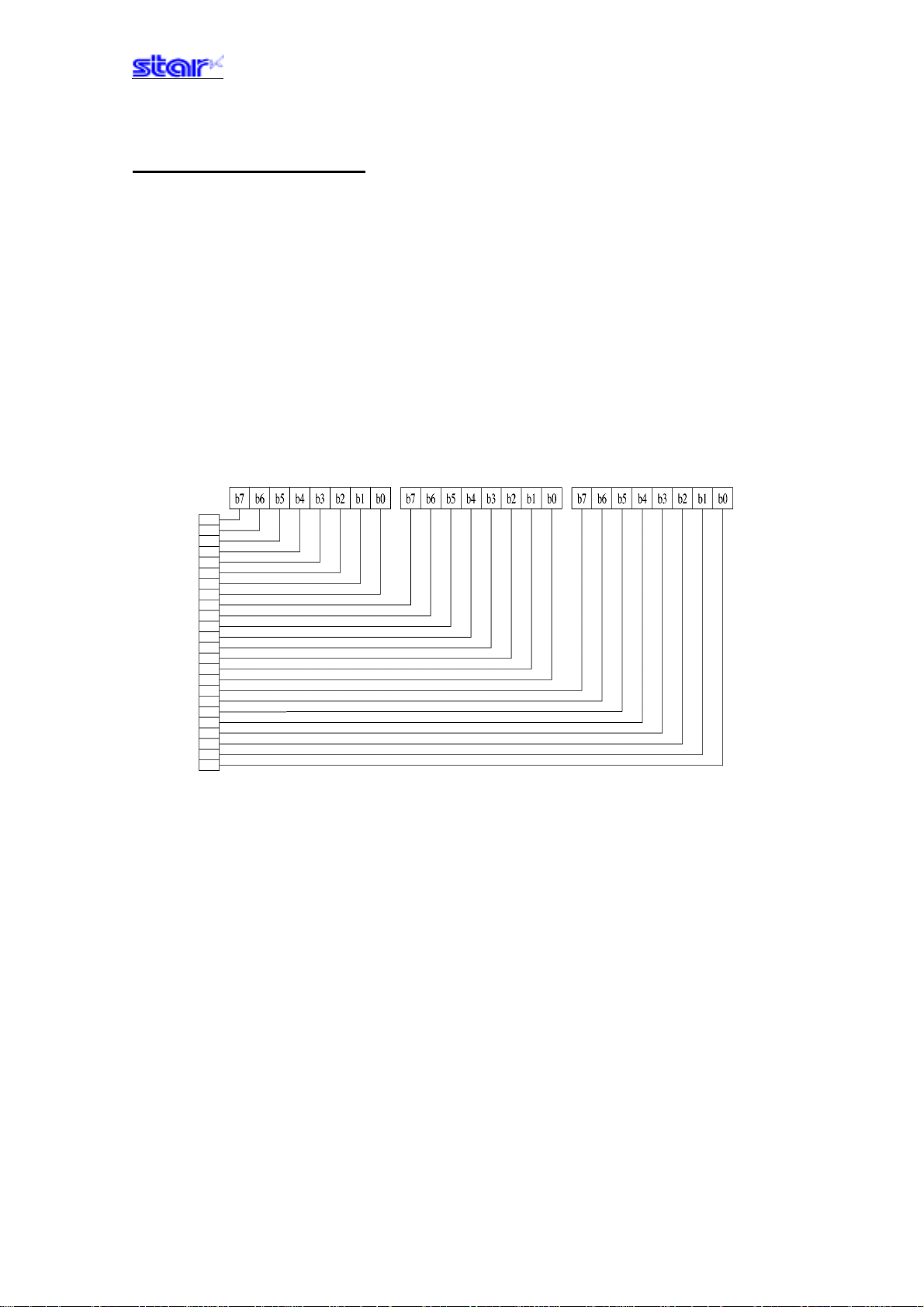
ESC X n1 n2 d1...dk
[Name] Fine density bit image (Compatible with 24 bit wire dots)
[Code] ASCII ESC X n1 n2 d1 ... dk
Hex. 1B 58 n1 n2 d1 ... dk
Decimal 2788n1n2d1 ...dk
[Defined Area] 1 ≤ (n1 + n2 x 256) ≤ printable region
k = {(n1 + n2 x 256) x 3}
0≤d≤255
[Initial Value] - - [Function] Prints input bit images with 8 dots/mm resolution for both horizontal and vertical.
The following shows the data processing in this command.
• When {(n1 + n2 x 256) x 3} exceeds the printable region, data after d1 is handled as normal
data.
• When {(n1 + n2 x 256) x 3} exceeds the printable region that is currently set, only the data in
the printing region is printed.
At this time, all data for the print region is discarded.
• If the current position already exceeds the print region, this command discards all data.
―――――――――――――――――――――――――――――――――――――――――― ――――――――――――――――――――――――――― ――――――――――――――――
STAR Line Mode Command Specifications 3-35
Page 52

3-3-9) Logo
ESC FS q n
[Name] Register logo
[Code] ASCII ESC FS q n [x11 x12 y11 y12 d1 ... dk]1 ... [xn1 xn2 yn1 yn2 d1 ... dk]n
Hex. 1B 1C 71 n [x11 x12 y11 y12 d1 ... dk]1 ... [xn1 xn2 yn1 yn2 d1 ... dk]n
Decimal 27 28 113 n [x11 x12 y11 y12 d1 ... dk]1 ... [xn1 xn2 yn1 yn2 d1 ... dk]n
[Defined Area] 1≤n≤255
[Initial Value] - - [Function] Parameter details
[x11 x12 y11 y12 d1...dk]1...[xn1 xn2 yn1 yn2 d1...dk]n
0≤xn1≤255, 0≤xn2≤3
1≤(xn1 + xn2 x 256)≤1023
0≤yn1≤255, 0≤yn2≤1
1≤(yn1 + yn2 x 256)≤288
0≤d≤255
k = {(xn1 + xn2 x 256) x (yn1 + yn2 x 256) x 8}
• n: Specifies registered logo count
• xn1, xn2: Horizontal size of registered logo {(xn1 + xn2 x 256) x 8} dots
• yn1, yn2: Vertical size of registered logo {(yn1 + yn2 x 256) x 8} dots
• d: Registered logo data
• k: Logo data count
This command should be specified at the top of the line.
When the first parameter is determined to be free of error, the printer starts processing this
command.
When logo register processing starts, all previously defined data is deleted.
(It is not possible to reregister a portion of a plurality of defined logo data.)
Logo registration numbers are defined in rising order from 1.
The logo definition region is approximately 256 bytes.
If the defined area specified by the parameter is not empty, or if there is an error in the parameter
specification, register processing is aborted. (The pre-registered and complete data is effective.)
The printer should be initialized if logo registration is completed or register processing is aborted.
If an error occurs while performing register processing (the time from when the first parameter is
OK until th printer initialization is completed after registering a logo), error processing,
mechanical operation and status processing cannot be performed.
The relationships between input data and the actual print are shown on the next page.
―――――――――――――――――――――――――――――――――――――――――― ――――――――――――――――――――――――――― ――――――――――――――――
STAR Line Mode Command Specifications 3-36
Page 53
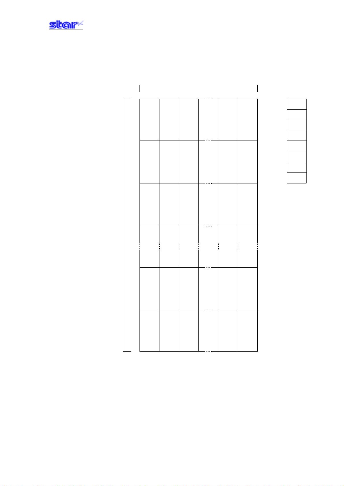
Relationships of logo and registered data
xn = xn1 + xn2 x 256, yn = yn1 + yn2 x 256
{(xn1 + xn2 x 256) x 8} dots
Data
MSB
d[11] d[21] d[n1]
(yn1 + yn2 x 256) bytes
(yn1 + yn2 x 256) x 8
d[12] d[22] d[n2]
dots
LSB
d[x1] d[x2] d[xn]
―――――――――――――――――――――――――――――――――――――――――― ――――――――――――――――――――――――――― ――――――――――――――――
STAR Line Mode Command Specifications 3-37
Page 54
ESC FS p n m
[Name] Print logo
[Code] ASCII ESC FS p n m
Hex. 1B 1C 70 n m
Decimal 27 28 112 n m
[Defined Area] 1≤n≤255
0≤m≤3
48≤m≤51 (”0”≤m≤”3”)
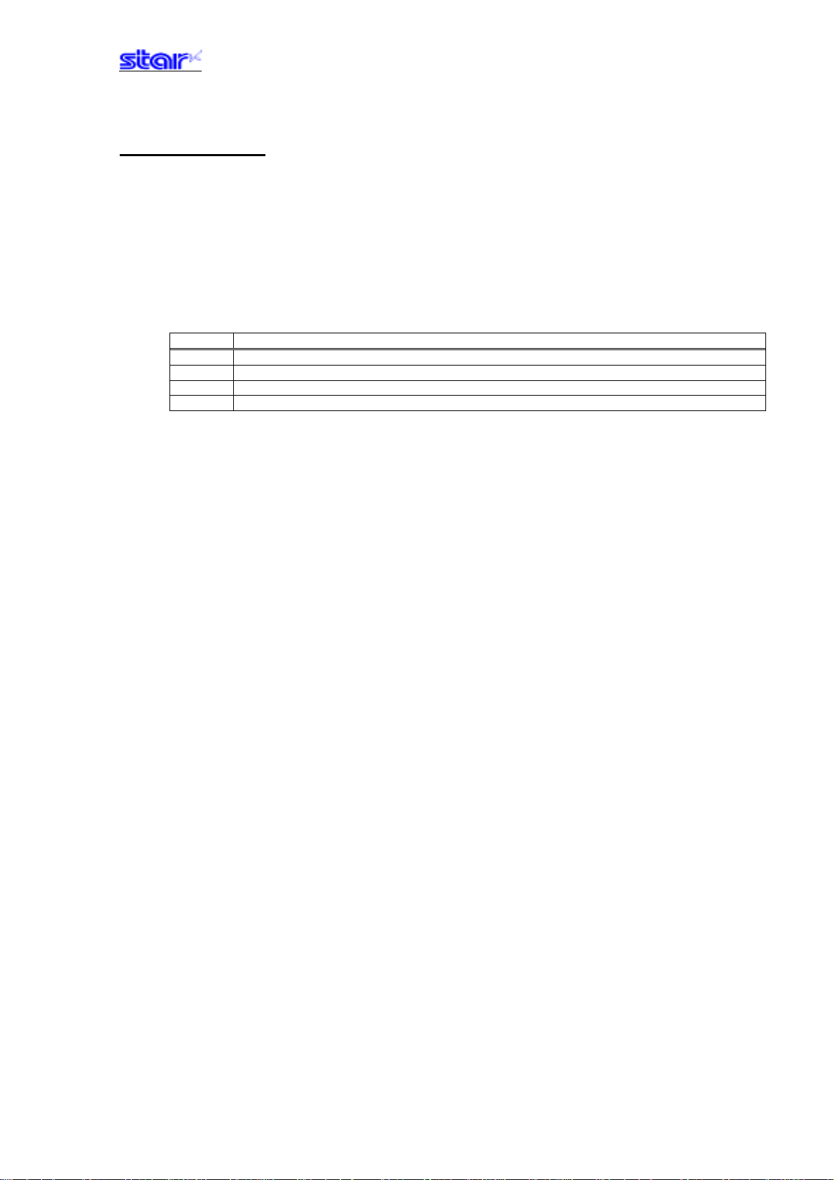
[Initial Value] - - [Function] Prints the logo of registration number n registered using the logo registration command (ESC FS
q) according to the print mode m.
m Logo print mode
0, 48 Normal mode
1, 49 Double wide mode
2, 50 Double high mode
3, 51 Double high/wide mode
If there is unprinted data in the line buffer, this command is executed after printing that data.
Therefore, it is not possible to print with other data in the same line (characters, bit images, bar
codes).
Form feed obeys the vertical print size of the logo.
If the logo horizontal print size exceeds the horizontal print region, the portion exceeding the area
is not printed.
Logos are printed according to the following command settings.
• Left margin (ESC I n)
• Right margin (ESC Q n)
• Position alignment (ESC GS a n)
• Absolut position movement (ESC GS R n1 n2)
• Upside-down printing (SI)
―――――――――――――――――――――――――――――――――――――――――― ――――――――――――――――――――――――――― ――――――――――――――――
STAR Line Mode Command Specifications 3-38
Page 55
3-3-10) Bar code
ESC b n1 n2 n3 n4 d1...dk RS
[Name]
[Code] ASCII ESC b n1 n2 n3 n4 d1 ... dk RS
Hex. 1B 62 n1 n2 n3 n4 d1 ... dk 1E
Decimal 2798n1n2n3n4d1 ...dk30
[Defined Area] 0≤n1≤8, 48≤n1≤56 (”0 ≤n1≤”8”)
1≤n2≤4, 49vn2≤52 (”1”≤n2≤”4”)
1≤n4≤255
n3 (bar code mode), d (bar code data), k (bar code data count) definitions differ according to the
type of bar code.
[Initial Value] - - [Function] Bar code printing is executed according to the following parameters.
If n1, n2, n3 and n4 are acquired and detected to be out of the defined area, data up to RS is
discarded.
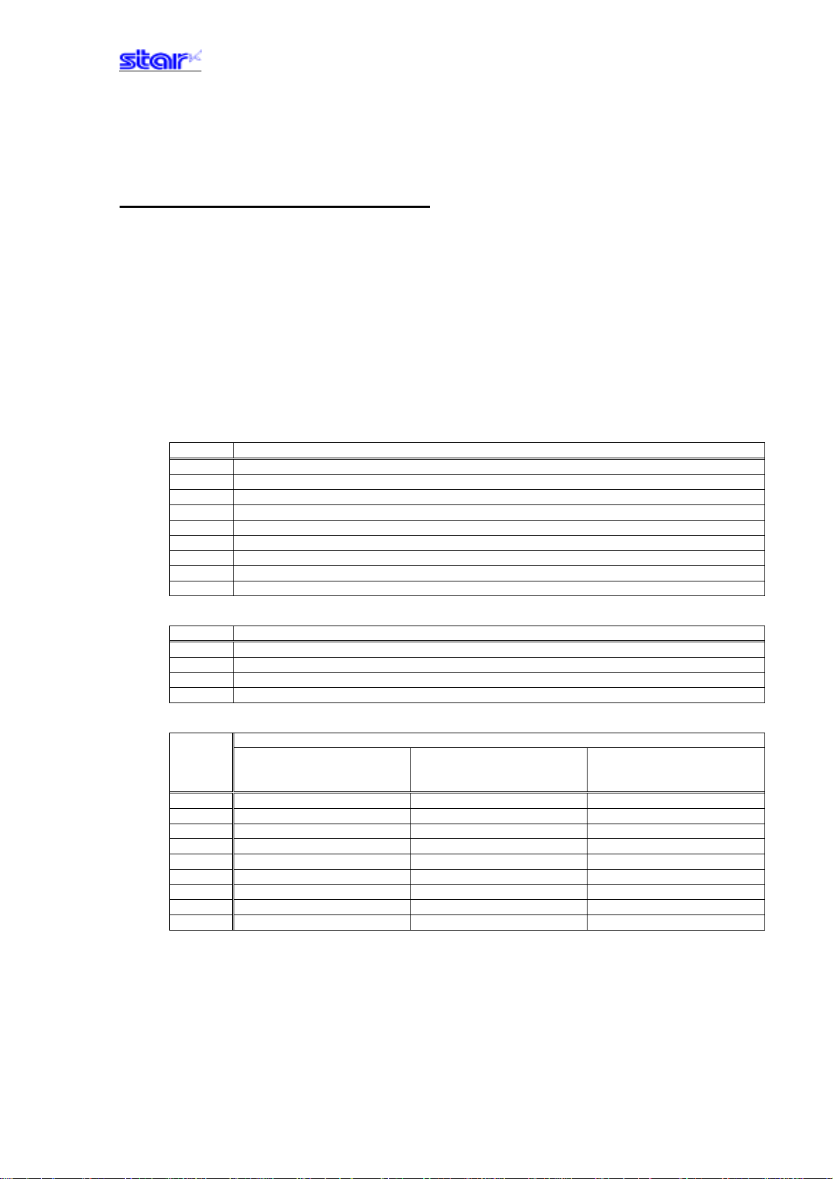
• n1 bar code type selection
n1 Bar code type
0, 48 UPC-E
1, 49 UPC-A
2, 50 JAN/EAN8
3, 51 JAN/EAN13
4, 52 Code39
5, 53 ITF
6, 54 Code128
7, 55 Code93
8, 56 NW-7
• n2 Under-bar character selection and added line feed selection
n2 Under-bar character selection and added line feed selection
1, 49 No added under-bar charactersExecutes line feed after printing a bar code
2, 50 Adds under-bar characters Executes line feed after printing a bar code
3, 51 No added under-bar charactersDoes not execute line feed after printing a bar code
4, 52 Adds under-bar characters Does not execute line feed after printing a bar code
• n3 bar code mode selection
n3 Bar code type
UPC-E, UPC-A, JAN/EAN8 Code39, NW-7 ITF
JAN/EAN13, Code128,
Code93
1, 49 Minimum module 2 dots Narrow : Wide = 2:6 dots Narrow : Wide = 2:5 dots
2, 50 Minimum module 3 dots Narrow : Wide = 3:9 dots Narrow : Wide = 4:10 dots
3, 51 Minimum module 4 dots Narrow : Wide = 4:12 dots Narrow : Wide = 6:15 dots
4, 52 - - - Narrow : Wide = 2:5 dots Narrow : Wide = 2:4 dots
5, 53 - - - Narrow : Wide = 3:8 dots Narrow : Wide = 4:8 dots
6, 54 - - - Narrow : Wide = 4:10 dots Narrow : Wide = 6:12 dots
7, 55 - - - Narrow : Wide = 2:4 dots Narrow : Wide = 2:6 dots
8, 56 - - - Narrow : Wide = 3:6 dots Narrow : Wide = 3:9 dots
9, 57 - - - Narrow : Wide = 4:8 dots Narrow : Wide = 4:12 dots
―――――――――――――――――――――――――――――――――――――――――― ――――――――――――――――――――――――――― ――――――――――――――――
STAR Line Mode Command Specifications 3-39
Page 56
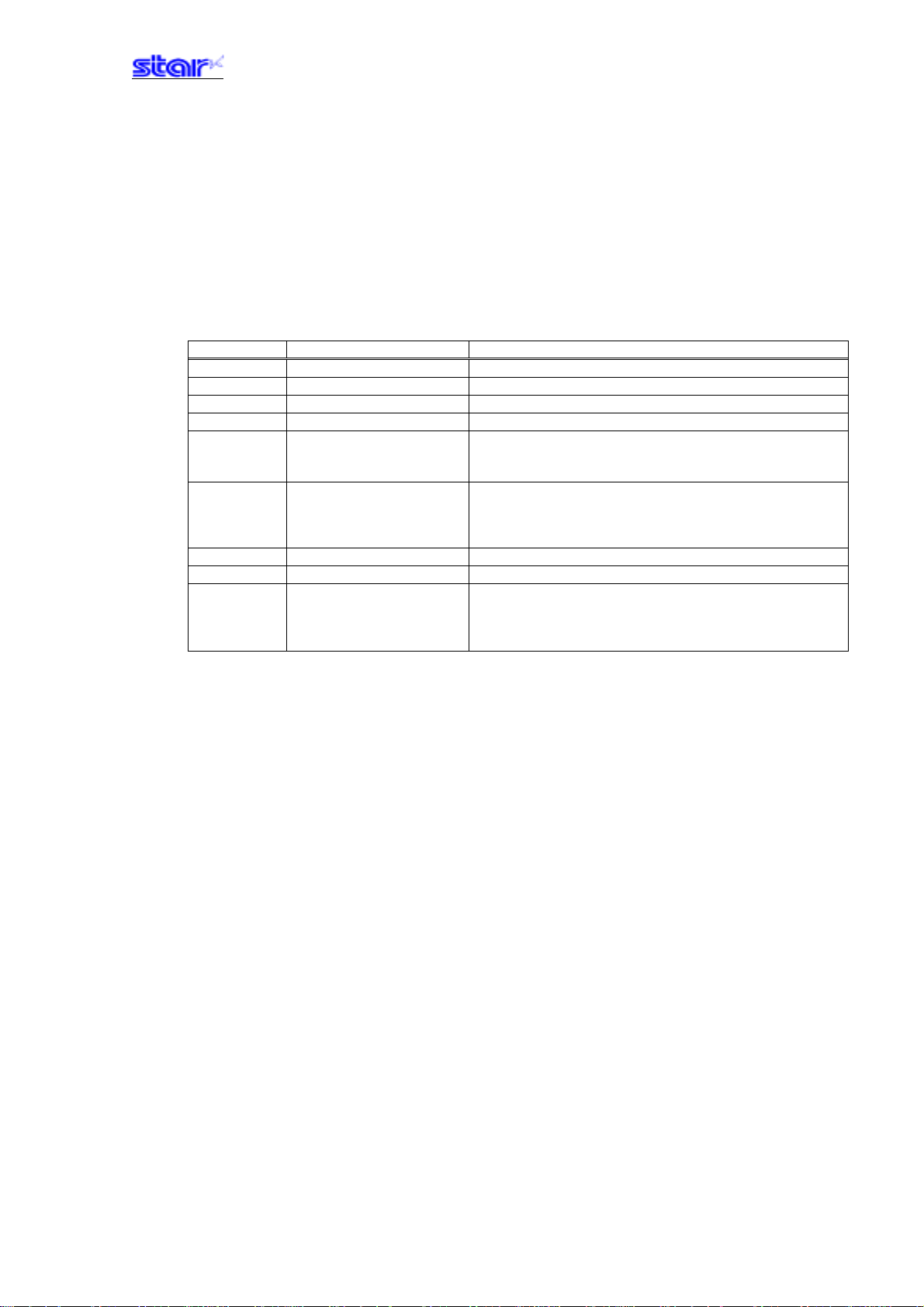
• n4 bar code height (dot count)
Specification A
When the height of the bar code is more than the form feed amount, the form feed amount is
automatically doubled.
Specification B
Form feed at (Bar code height + underbar characters)
Supplement:
Specification Type A and Specification Type B differ per model.
See the COMMAND LIST BY MODEL in Chapter 6. SPECIAL APPENDIX for your model.
• k (Bar code data count), d (Bar code data)
Bar code type Defined area of k Defined area of d
UPC-E
UPC-A
JAN/EAN8
JAN/EAN13
Code39
11≤≤12 48≤d≤57 (”0”≤d≤”9”)
11≤≤12 48≤d≤57 (”0”≤d≤”9”)
7≤≤848≤d≤57 (”0”≤d≤”9”)
12≤≤13 48≤d≤57 (”0”≤d≤”9”)
1≤ 48≤d≤57 (”0”≤d≤”9”)
65≤d≤90 (”A”≤d≤”Z”)
32, 36, 37, 43, 45, 46, 47 (SP, ”$”, ”%”, ”+”, ”-“, ”.”, ”/”)
ITF
1≤
48≤d≤57 (”0 ≤d≤”9”)
When an odd number: 0 is
automatically applied to
the top.
Code128
Code93
NW-7
1≤ 0≤d≤127
1≤ 0≤d≤127
1≤ 48≤d≤57 (”0”≤d≤”9”)
65≤d≤68 (”A”≤d≤”D”)
36, 43, 45, 46, 47, 58 (”$”, ”+”, ”-“, ”.”, ”/”, ”:”)
97, 98, 99, 100 (”a”, ”b”, ”c”, ”d”)
• UPC – E: k = 11 (or 12)
The 12
th
check digit is automatically applied, so it is specified and
ignored.
The command is ignored for data that cannot be shortened.
Automatically converts data to shortened form.
• UPC – A: k = 11 (or 12)
The 12
th
check digit is automatically applied, so it is specified and
ignored.
• JAN/EAN – 8: k = 7 (or 8)
th
The 8
check digit is automatically applied, so it is specified and ignored.
• JAN/EAN -13: k = 12 (or 13)
The 13th check digit cannot be automatically applied, so it is specified and
ignored.
• CODE 39: k is freely set, and maximum value differs according to the
mode.
Start/stop code (*) is automatically applied.
• ITF: k is freely set, and maximum value differs according to the mode.
If data is oddly numbered, a 0 is applied to the top.
• CODE 128: k is freely set, and maximum value differs according to the
mode and the print character type.
The check character is automatically applied.
• CODE 93: k is freely set, and maximum value differs according to the
mode and the print character type.
The check character (?) is automatically applied.
• NW7: k is freely set, and maximum value differs according to the mode
and the print character type.
Start/stop codes included in the data (not automatically applied).
―――――――――――――――――――――――――――――――――――――――――― ――――――――――――――――――――――――――― ――――――――――――――――
STAR Line Mode Command Specifications 3-40
Page 57
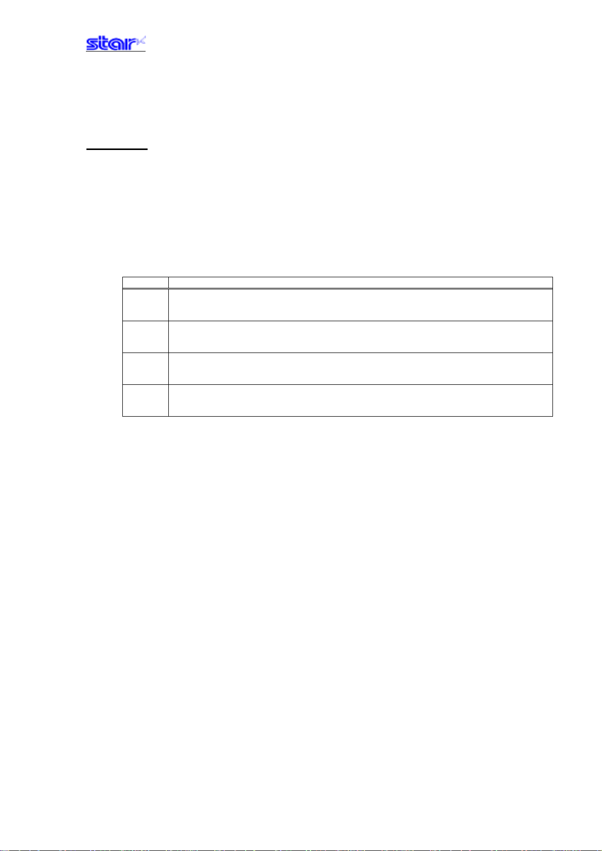
3-3-11) Cutter control
ESC d n
[Name] Auto-cutter
[Code] ASCII ESC d n
Hex. 1B 64 n
Decimal 27 100 n
[Defined Area] 0≤d≤3
48≤d≤51 (”0”≤d≤”3”)
[Initial Value] - - [Function] Exectes the auto-cutter.
After auto-cutter is executed, the printer considers that to be the top of the page.
n Auto cutter
0, 48 Full cut at the current position.
Print data in line buffer is printed before a full cut.
This command is ignored if the printer is not equipped with an auto-cutter.
1, 49 Partial cut at the current position.
Print data in line buffer is printed before a partial cut.
This command is ignored if the printer is not equipped with an auto-cutter.
2, 50 Paper is fed to cutting position, then a full cut.
Print data in line buffer is printed before the operation described above.
This command is ignored if the printer is not equipped with an auto-cutter.
3, 51 Paper is fed to cutting position, then a partial cut.
Print data in line buffer is printed before the operation described above.
This command is ignored if the printer is not equipped with an auto-cutter.
(*) The auto-cutter function operates in the following ways on models that only have a full cut or a
partial cut.
• Models that perform only a full cut. Executes a full cut when there are
• Models that perform only a partial cut. Executes a partial cut when there are for instructions
(*) When connected with a presenter, executes a full cut when instructed for a partial cut.
instructions calling for a partial cut.
calling for a full cut.
―――――――――――――――――――――――――――――――――――――――――― ――――――――――――――――――――――――――― ――――――――――――――――
STAR Line Mode Command Specifications 3-41
Page 58
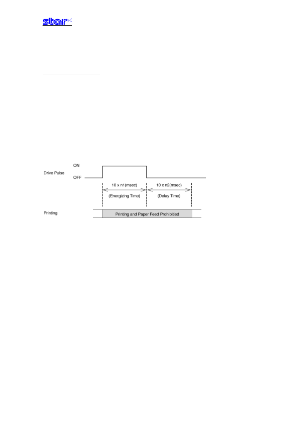
3-3-12 External device drive
ESC BEL n1 n2
[Name] Set external drive device 1 pulse width
[Code] ASCII ESC BEL n1 n2
Hex. 1B 07 n1 n2
Decimal 27 7 n1 n2
[Defined Area] 1≤n1≤127
1≤n2≤127
[Initial Value] n1 = 20 (Energizing time: 200 msec)
n2 = 20 (Delay time: 200 msec)
[Function] Sets the energizing and delay times for drive of the external device.
• Energizing time = 10 x n1 (ms)
• Delay time = 10 x n2 (ms)
―――――――――――――――――――――――――――――――――――――――――― ――――――――――――――――――――――――――― ――――――――――――――――
STAR Line Mode Command Specifications 3-42
Page 59

BEL
[Name] External device 1 drive instruction
[Code] ASCII BEL
Hex. 07
Decimal 7
[Defined Area] - - [Initial Value] - - [Function] Executes the external device drive conditions set according to the command to set the external
drive device pulse width (ESC BEL n1 n2).
As with other commands, it temporarily stores data in the data buffer, then executes in the order
received.
External device 1 and external device 2 cannot be executed simultaneously.
FS
[Name] External device 1 drive instruction
[Code] ASCII FS
Hex. 1C
Decimal 28
[Defined Area] - - [Initial Value] - - [Function] Executes the external device drive conditions set according to the command to set the external
drive device pulse width (ESC BEL n1 n2).
As with other commands, it temporarily stores data in the data buffer, then executes in the order
received.
External device 1 and external device 2 cannot be executed simultaneously.
―――――――――――――――――――――――――――――――――――――――――― ――――――――――――――――――――――――――― ――――――――――――――――
STAR Line Mode Command Specifications 3-43
Page 60

SUB
[Name] External device 2 drive instruction
[Code] ASCII SUB
Hex. 1A
Decimal 26
[Defined Area] - - [Initial Value] - - -
[Function] Drives external device 2.
The energizing time and delay time for the external device 2 are fixed at 200 ms each.
As with other commands, it temporarily stores data in the data buffer, then executes in the order
received.
External device 1 and external device 2 cannot be executed simultaneously.
EM
[Name] External device 2 drive instruction
[Code] ASCII EM
Hex. 19
Decimal 25
[Defined Area] - - [Initial Value] - - [Function] Drives external device 2.
The energizing time and delay time for the external device 2 are fixed at 200 ms each.
As with other commands, it temporarily stores data in the data buffer, then executes in the order
received.
External device 1 and external device 2 cannot be executed simultaneously.
―――――――――――――――――――――――――――――――――――――――――― ――――――――――――――――――――――――――― ――――――――――――――――
STAR Line Mode Command Specifications 3-44
Page 61

3-3-13) Print settings
ESC RS d n
[Name]
[Code] ASCII ESC RS d n
[Defined Area] 0≤n≤15
[Initial Value] Memory switch setting
[Function] Sets print density.
Set print density
Hex. 1B 1E 64 n
Decimal 27 30 100 n
48≤n≤57 (”0”≤n≤”9”)
65≤n≤70 (”0”≤n≤”F”)
This command stops printing to be executed.
n
0, 48
1, 49
2, 50
3, 51
4, 52
5, 53
6, 54
7, 55
8, 56
9, 57
10, 65
11, 6 6
12, 67
13, 68
14, 69
15, 70
Print density
Print density 1.3
Print density 1.2
Print density 1.1
Print density 1.0
Print density 0.9
Print density 0.8
Print density 0.7
(Reserved)
(Reserved)
(Reserved)
(Reserved)
(Reserved)
(Reserved)
(Reserved)
(Reserved)
(Reserved)
―――――――――――――――――――――――――――――――――――――――――― ――――――――――――――――――――――――――― ――――――――――――――――
STAR Line Mode Command Specifications 3-45
Page 62
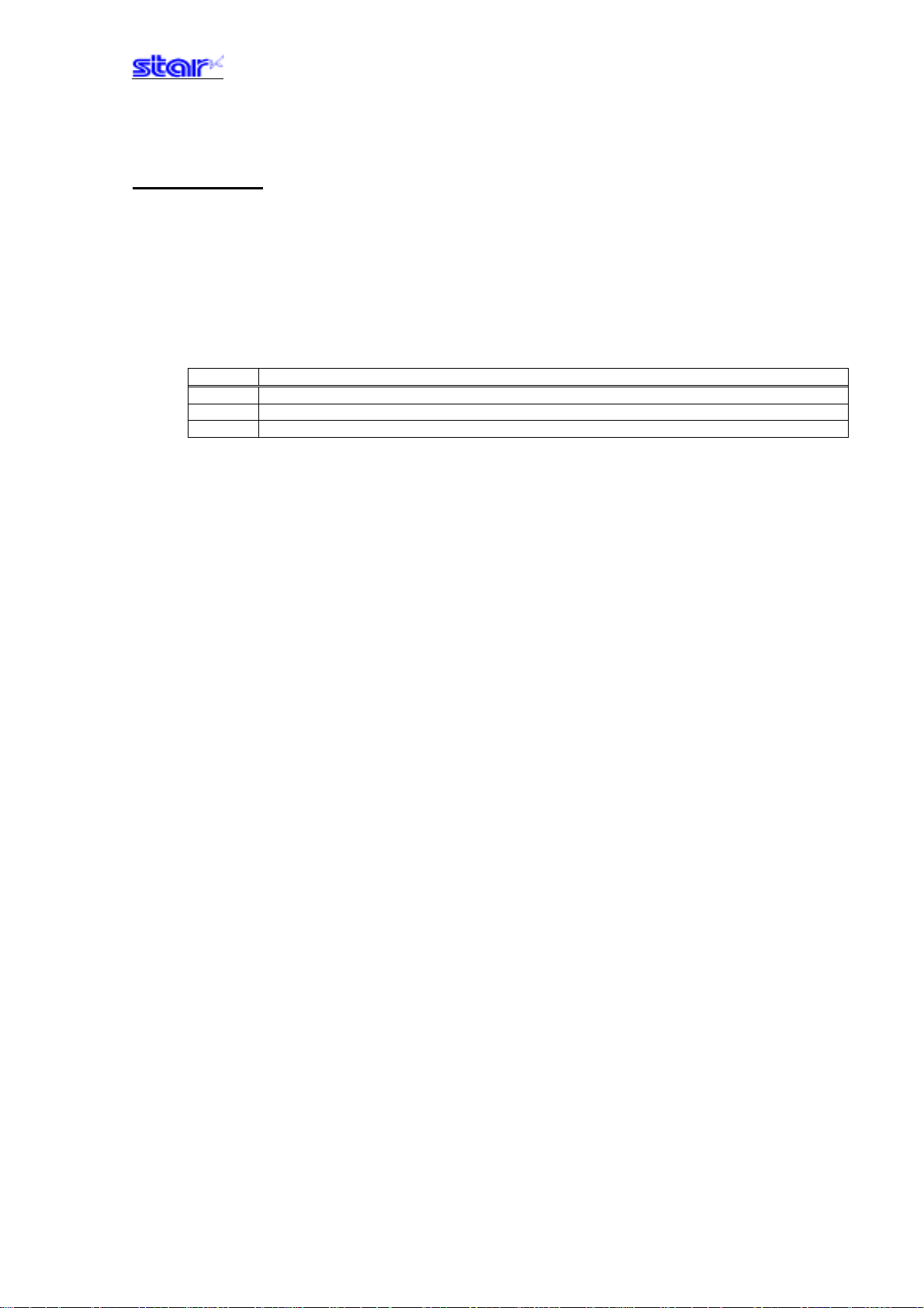
ESC RS r n
[Name]
[Code] ASCII ESC RS r n
[Defined Area] 0≤n≤3
[Initial Value] Memory switch setting
[Function] Sets print speed.
Set print speed
Hex. 1B 1E 72 n
Decimal 27 30 114 n
48≤n≤51 (”0”≤n≤”3”)
This command stops printing to be executed.
n
0, 48
1, 49
2, 50
Print speed
High speed
Mid-speed
Slow speed
―――――――――――――――――――――――――――――――――――――――――― ――――――――――――――――――――――――――― ――――――――――――――――
STAR Line Mode Command Specifications 3-46
Page 63
3-3-14) Status
ESC RS a n
[Name] Set status transmission conditions
[Code] ASCII ESC RS a n
Hex. 1B 1E 61 n
Decimal 27 30 97 n
[Defined Area] 0≤n≤3
48≤n≤51(”0”≤n≤”51”)
[Initial Value] Set by DIP switches and memory switches.
[Function] Sets the status transmission conditions.
See Appendix 2 for details regarding ASB status.
Settings of this command are unaffected by the ESC @ command.
Specification A
n Status transmission conditions
0, 48 ASB invalid
1, 49 ASB valid
Specification B
n Status transmission condition settings
0, 48 ASB invalid
1, 49 ASB valid
―――――――――――――――――――――――――――――――――――――――――― ――――――――――――――――――――――――――― ――――――――――――――――
STAR Line Mode Command Specifications 3-47
Page 64

ESC ACK SOH
[Name] Real-time printer status (ASB status)
[Code] ASCII ESC ACK SOH
Hex. 1B 06 01
Decimal 27 6 1
[Defined Area] - - [Initial Value] - - [Function] Sends ASB status information to the host.
This command is not used when ASB is valid.
See Appendix 2, Automatic Status for details regarding ASB status.
ENQ
[Name] Real-time printer status (1)
[Code] ASCII ENQ
Hex. 05
Decimal 5
[Defined Area] - - [Initial Value] - - [Function] Sends 1 byte of the following the printer status
This command is not used when ASB is valid.
See Appendix 2, ENQ Command Status for details regarding status.
EOT
[Name] Real-time printer status (2)
[Code] ASCII EOT
Hex. 04
Decimal 4
[Defined Area] - - [Initial Value] - - [Function] Sends 1 byte of the following the printer status
This command is not used when ASB is valid.
See Appendix 2, EOT Command Status for details regarding status.
―――――――――――――――――――――――――――――――――――――――――― ――――――――――――――――――――――――――― ――――――――――――――――
STAR Line Mode Command Specifications 3-48
Page 65

3-3-15) Chinese characters
ESC p
[Name] Specify JIS Chinese character mode
[Code] ASCII ESC p
Hex. 1B 70
Decimal 27 112
[Defined Area] - - [Initial Value] JIS Chinese character mode cancelled
[Function] Specifies JIS Chinese character mode
When in JIS Chinese character mode, character codes are all handled as 2 byte Chinese
characters (First byte: upper code; second byte: lower code).
This command is ignored for models not equipped with Japanese and Chinese characters and
when the specification for the location of use is specified as SBCS (single byte countries) by the
memory switch.
ESC q
[Name] Cancel JIS Chinese character mode
[Code] ASCII ESC q
Hex. 1B 71
Decimal 27 113
[Defined Area] - - [Initial Value] JIS Chinese character mode cancelled
[Function] Cancel JIS Chinese character mode
―――――――――――――――――――――――――――――――――――――――――― ――――――――――――――――――――――――――― ――――――――――――――――
STAR Line Mode Command Specifications 3-49
Page 66

ESC $ n
[Name] Specify/cancel Shift JIS Chinese character mode
[Code] ASCII ESC $ N
Hex. 1B 24 N
Decimal 27 36 N
[Defined Area] - - [Initial Value] Memory switch setting
[Function] Specifies and cancels the shift JIS Chinese character mode.
When in shift JIS Chinese character mode, character codes are all handled as 2 byte Chinese
characters (First byte: upper code; second byte: lower code).
This command is ignored for models not equipped with Japanese and Chinese characters and
when the specification for the location of use is specified as SBCS (single byte countries) by the
memory switch.
n Shift JIS Chinese character mode
0, 48 Cancels shift JIS Chinese character mode
1, 49 Specifies shift JIS Chinese character mode
―――――――――――――――――――――――――――――――――――――――――― ――――――――――――――――――――――――――― ――――――――――――――――
STAR Line Mode Command Specifications 3-50
Page 67

ESC s n1 n2
[Name] Set 2 byte Chinese character left/right spaces
[Code] ASCII ESC s n1 n2
Hex. 1B 73 n1 n2
Decimal 27 115 n1 n2
[Defined Area] 0≤n1≤7
48≤n1≤55 (”0”≤n1≤”7”)
0≤n2≤15
48≤n2≤57 (”0”≤n2≤”9”)
65≤n2≤70 (”A”≤n2≤”F”)
[Initial Value] Memory switch setting
[Function] Adds n1 dot left space and n2 dot right space to Chinese characters.
This command is ignored for models not equipped with Chinese fonts (for overseas) and when
the specification for the location of use is specified as SBCS (single byte countries) by the
memory switch.
ESC t n1 n2
[Name] Set 1 byte Chinese character left/right spaces
[Code] ASCII ESC t n1 n2
Hex. 1B 74 n1 n2
Decimal 27 116 n1 n2
[Defined Area] 0≤n1≤7
48≤n1≤55 (”0”≤n1≤”7”)
0≤n2≤15
48≤n2≤57 (”0”≤n2≤”9”)
65≤n2≤70 (”A”≤n2≤”F”)
[Initial Value] Memory switch setting
[Function] Adds n1 dot left space and n2 dot right space to 1 byte characters.
This command is ignored for models not equipped with Chinese fonts (for overseas) and when
the specification for the location of use is specified as SBCS (single byte countries) by the
memory switch.
―――――――――――――――――――――――――――――――――――――――――― ――――――――――――――――――――――――――― ――――――――――――――――
STAR Line Mode Command Specifications 3-51
Page 68
ESC r c1 c2 d1...dk
[Name] Register Chinese download characters
[Code] ASCII ESC r c1 c2 d1 ... dk
Hex. 1B 72 c1 c2 d1 ... dk
Decimal 27 114 c1 c2 d1 ... dk
[Defined Area] 0≤d≤255
k=72
c1 and c2 differ according to specifications and code type (see table below).
[Initial Value] All spaces
[Function] Registers Chinese download characters to c1 and c2 addresses.
Those already registered to these addresses are overwritten. If c1 and c2 are outside of the
defined are or the printer is model not equipped with Chinese fonts (for overseas) and when the
specification for the location of use is specified as SBCS (single byte countries) by the memory
switch, the printer discards up to d1 and dk.
This command exists in models that have the specifications of A and B below. (See the “Special
Appendix, Command Table per Model” for details.)
Specification A
Specification c1 c2 Registration count
Japanese char./JIS type c1=77h
Specification B
Specification c1 c2 Registration count
Japanese char./JIS type c1=77h 21h≤c2≤7Eh 94 characters
Japanese char./Shift JIS type c1=ECh 40h≤c2≤7Eh
Chinese characters c1=FEh A1h≤c2≤FEh 94 characters
(*) The registration region is the same for Japanese characters in JIS or shift JIS.
Supplement:
Specification Type A and Specification Type B differ per model.
See the COMMAND LIST BY MODEL in Chapter 6. SPECIAL APPENDIX for your model.
30h≤c2≤4Fh
80h≤c2≤9Eh
32 characters
94 characters
Vertical
24 Dots
Horizontal
24 Dots
d1 ●●●●●●●●d2 ●●●●●●●●d3 ●●●●●●●●
d4 ●●●●●●●●d5 ●●●●●●●●d6 ●●●●●●●●
d7 ●●●●●●●●d8 ●●●●●●●●d9 ●●●●●●●●
d10 ●●●●●●●●d11 ●●●●●●●●d12 ●●●●●●●●
d13 ●●●●●●●●d14 ●●●●●●●●d15 ●●●●●●●●
d16 ●●●●●●●●d17 ●●●●●●●●d18 ●●●●●●●●
d19 ●●●●●●●●d20 ●●●●●●●●d21 ●●●●●●●●
d22 ●●●●●●●●d23 ●●●●●●●●d24 ●●●●●●●●
d25 ●●●●●●●●d26 ●●●●●●●●d27 ●●●●●●●●
d28 ●●●●●●●●d29 ●●●●●●●●d30 ●●●●●●●●
d31 ●●●●●●●●d32 ●●●●●●●●d33 ●●●●●●●●
d34 ●●●●●●●●d35 ●●●●●●●●d36 ●●●●●●●●
d37 ●●●●●●●●d38 ●●●●●●●●d39 ●●●●●●●●
d40 ●●●●●●●●d41 ●●●●●●●●d42 ●●●●●●●●
d43 ●●●●●●●●d44 ●●●●●●●●d45 ●●●●●●●●
d46 ●●●●●●●●d47 ●●●●●●●●d48 ●●●●●●●●
d49 ●●●●●●●●d50 ●●●●●●●●d51 ●●●●●●●●
d52 ●●●●●●●●d53 ●●●●●●●●d54 ●●●●●●●●
d55 ●●●●●●●●d56 ●●●●●●●●d57 ●●●●●●●●
d58 ●●●●●●●●d59 ●●●●●●●●d60 ●●●●●●●●
d61 ●●●●●●●●d62 ●●●●●●●●d63 ●●●●●●●●
d64 ●●●●●●●●d65 ●●●●●●●●d66 ●●●●●●●●
d67 ●●●●●●●●d68 ●●●●●●●●d69 ●●●●●●●●
d70 ●●●●●●●●d71 ●●●●●●●●d72 ●●●●●●●●
bit7 bit6 bit5 Bit4 bit3 bit2 bit1 bit0 bit7 bit6 bit5 bit4 bit3 bit2 bit1 bit0 bit7 bit6 bit5 bit4 bit3 bit2 bit1 bit0
●: Font data/○: Invalid data
―――――――――――――――――――――――――――――――――――――――――― ――――――――――――――――――――――――――― ――――――――――――――――
STAR Line Mode Command Specifications 3-52
Page 69

3-3-16) Others
CAN
[Name] Cancel print data and initialize commands
[Code] ASCII CAN
Hex. 18
Decimal 24
[Defined Area] - - [Initial Value] - - [Function] When the reception buffer and line buffer are cleared, the set commands are initialized.
Immediately executed not when taking out from the reception buffer, but when received from the
host.
DIPSW re-readin is not performed.
The following shows the specifications that are not initialized by this command.
• Set print density
• Set print speed
• Set 2 color print mode
• Print color in 2 color print mode
• External device drive condition
―――――――――――――――――――――――――――――――――――――――――― ――――――――――――――――――――――――――― ――――――――――――――――
STAR Line Mode Command Specifications 3-53
Page 70

ESC @
[Name] Command initialization
[Code] ASCII ESC @
Hex. 1B 40
Decimal 27 64
[Defined Area] - - [Initial Value] - - [Function] Initializes each command after printing data in the line buffer.
However, printers with memory switch settings are initialized to the memory switch settings.
DIPSW re-readin is not performed.
• ANK characters, Chinese character adornment, expansion
• Chinese character mode
• ANK right space
• Chinese character left/right spaces
• Character pitch
• International characters
• Code page
• Set slash zero
• Set specify/cancel external character (external register character data is retained)
• Page length
• Current position (move to top of page, top of line)
• Horizontal tab/Vertical tab
• Line feed amount
• Set upside-down, position alignment
• Left/right margins
The following shows the specifications that are not initialized by this command.
• Set print density
• Set print speed
• Set 2 color print mode
• Print color in 2 color print mode
• External device drive condition
―――――――――――――――――――――――――――――――――――――――――― ――――――――――――――――――――――――――― ――――――――――――――――
STAR Line Mode Command Specifications 3-54
Page 71
ESC GS # m N n1 n2 n3 n4 LF NUL
[Name] Set memory switch
[Code] ASCII ESC GS # m N n1 n2 n3 n4 LF
Hex. 1B 1D 23 m N n1 n2 n3 n4 0A 00
Decimal 272935 m Nn1n2n3n410 0
[Defined Area] m = 87, 84, 44, 43, 45, 64 ( m = “W”, “T”, “,”, “+”, “-”, “@” )
48≤n1≤57 (“0”≤n1≤ “9”) , 65≤n1≤70 (“A” ≤n1≤ “F”), 97≤n1≤102 (“a”≤n1≤ “f”)
48≤n2≤57 (“0”≤n2≤ “9”) , 65≤n2≤70 (“A”≤n2≤ “F”), 97≤n2≤102 (“a”≤n2≤ “f”)
48≤n3≤57 (“0”≤n3≤ “9”) , 65≤n3≤70 (“A”≤n3≤ “F”), 97≤n3≤102 (“a”≤n3≤ “f”)
48≤n4≤57 (“0”≤n4≤ “9”) , 65≤n4≤70 (“A”≤n4≤ “F”), 97≤n4≤102 (“a”≤n4≤ “f”)
Specification A
48≤N≤57 (“0”≤N≤ “9”) , 65≤N≤70 (“A”≤N≤ “F”), 97≤N≤102 (“a”≤N≤ “f”)
Specification B
48≤N≤57 (“0”≤N≤ “9”) , 65≤N≤70 (“A”≤N “F”), 97≤N≤102 (“a”≤N≤ “f”)
N = 85 (U) User defined area
Supplement:
Specification Type A and Specification Type B differ per model.
See the COMMAND LIST BY MODEL in Chapter 6. SPECIAL APPENDIX for your model.
[Initial Value] - - [Function] Sends command to write after defining memory switch using the definition command specified by
the following classes.
Memory switch information defined by the command to write is written to the volatile memory.
When writing to the volatile memory by the command to write, the printer executes a reset.
This command exists in models that have the specifications of A and B indicated in the above
defined areas.
Models having specifications B can register any 16 bit data by specifying N = 85 (U). (See the
“Special Appendix, Command Table per Model” for details per model.)
UL
Functions Class m N n1 n2 n3 n4
Definition data write and reset Write W Fixed at 0 Fixed at 0000
Definition data write and reset and
self print
Data definition (data specification) Definition “, ” N n1 n2 n3 n4
Data definition (specify bit and set) Definition “+” N n1 n2 n3 n4
Data definition (specy bit and clear) Definition “-” N n1 n2 n3 n4
Definition data (all data initialized) Definition “@” Fixed at 0 Fixed at 0000
• m : Mode selection
• N : Memory switch number to specify
• n1 n2 n3 n4 : Specify data m = (,) Specify data
m = (+) Bit number to set
m = (-) Bit number to clear
Write T Fixed at 0 Fixed at 0000
―――――――――――――――――――――――――――――――――――――――――― ――――――――――――――――――――――――――― ――――――――――――――――
STAR Line Mode Command Specifications 3-55
Page 72
ESC ? LF NUL
[Name] Reset printer (execute self print)
[Code] ASCII ESC ? LF NUL
Hex. 1B 3F 0A 00
Decimal 27 63 10 0
[Defined Area] - - [Initial Value] - - [Function] Hardware resets the printer and executes on self print.
After sending this command, the next data is not sent until the printer is online (in a state wherein
it can receive data).
When resetting the printer, the following processes are performed.
I/F Mode Process
Parallel - - - BUSY output
RS-232C DTR mode DTR mark outpu
Xon/Xoff mode Xoff output
―――――――――――――――――――――――――――――――――――――――――― ――――――――――――――――――――――――――― ――――――――――――――――
STAR Line Mode Command Specifications 3-56
Page 73

3-4) Raster Graphics Command Details
Raster graphics are command types and incidental specifications that enable high speed and high quality printing of
graphics.
The following shows the characteristics and specifications for raster graphics.
• Defines the raster mode command as the STAR line mode extension set.
Basically no restrictions set in use of conventional STAR line mode.
STAR Page Mode cannot be used.
• Handles high speed data transmission
When using IEEE 1284, data transmission rate of 80 to 100 kbytes ensured.
• Handles IEEE 1284, USB and Ethernet I/F (RS-232C not applicable)
• Handles both fixed length/variable length mode
• Print speed selectable
• Post printing cut operation selectable
• All settings possible by Raster commands.
Most settings are possible without DIPSW/memory switch settings.
• Supports printer driver handling raster mode
The following shows the raster command details.
Note that if not specifically noted, the following commands are effective only in rastr mode and the commands are
ignored (4 bytes ignored) when other than the raster mode. The raster image buffer in the command details
described below indicate the raster dedicated image buffer, the length thereof (vertical direction dot count) differing
between models.
―――――――――――――――――――――――――――――――――――――――――― ――――――――――――――――――――――――――― ――――――――――――――――
STAR Line Mode Command Specifications 3-57
Page 74

ESC * r R
[Name] Initialize raster mode
[Code] ASCII ESC * r R
Hex. 1B 2A 72 52
Decimal 27 42 114 82
[Defined Area] - - [Initial Value] - - [Function] Initializes raster mode.
This command is also effective when not in the raster mode.
However, initialization of the raster mode with this command is executed when entering the
raster mode.
The following settings are initialized using this command.
• Raster page length setting (ESC * r P n NUL)
• Raster print quality setting (ESC * Q n NUL)
• Raster print quality setting (ESC * r K n NUL)
• Raster top margin setting (ESC * r T n NUL)
• Raster left margin setting (ESC * r m l n NUL)
• Raster right margin setting (ESC * r m r n NUL)
• Raster EOT mode setting (ESC FF EOT)
• Raster FF mode setting (ESC FF NUT)
• Raster image buffer clear
Note that when entering the raster mode, it executes the same process as initialization of the
raster mode using this command.
However, because initialization is not performed when entering the raster mode only for the
following settings, when initializing the following it sends this initialization command.
• Raster data print color setting (ESC * r K n NUL)
―――――――――――――――――――――――――――――――――――――――――― ――――――――――――――――――――――――――― ――――――――――――――――
STAR Line Mode Command Specifications 3-58
Page 75

ESC * r A
[Name] Enter raster mode
[Code] ASCII ESC * r A
Hex. 1B 2A 72 41
Decimal 27 42 114 65
[Defined Area] - - [Initial Value] - - [Function] Enters raster mode.
This command is ignored when in the raster mode.
The following shows the details regard processing of this command.
(1) Reception of this command.
(2) When using parallel I/F, IEEE 1284 reverse mode is prohibited.
(3) All data remaining in the reception buffer and image buffer is printed equivalent to the FF
command.
(4) Initialize raster mode
(5) Enter raster mode
When in the raster mode, the raster mode is initialized.
The following shows the contents of the initialization.
• Raster page length setting (ESC * r P n NUL)
• Raster print quality setting (ESC * Q n NUL)
• Raster top margin setting (ESC * r T n NUL)
• Raster left margin setting (ESC * r m l n NUL)
• Raster right margin setting (ESC * r m r n NUL)
• Raster EOT mode setting (ESC FF EOT)
• Raster FF mode setting (ESC FF NUT)
• Raster image buffer clear
(*) Only raster data print color setting is not initialized when entering the raster mode.
―――――――――――――――――――――――――――――――――――――――――― ――――――――――――――――――――――――――― ――――――――――――――――
STAR Line Mode Command Specifications 3-59
Page 76

ESC * r B
[Name] Quit raster mode
[Code] ASCII ESC * r B
Hex. 1B 2A 72 42
Decimal 27 42 114 66
[Defined Area] - - [Initial Value] - - [Function] Quits raster mode.
When quitting the raster mode, if there is raster data remaining in the image buffer of the raster
mode, it quits the raster mode after executing the raster EOT mode.
Note that with this command, IEEE 1284 reverse mode is allowed in parallel I/F and it sets the
top of page with the line mode.
ESC * r C
[Name] Clear raster data
[Code] ASCII ESC * r C
Hex. 1B 2A 72 43
Decimal 27 42 114 67
[Defined Area] - - [Initial Value] - - [Function] Clears image buffer data in the raster mode.
―――――――――――――――――――――――――――――――――――――――――― ――――――――――――――――――――――――――― ――――――――――――――――
STAR Line Mode Command Specifications 3-60
Page 77
ESC * r D n NUL
[Name] Drawer drive
[Code] ASCII ESC * r D n
Hex. 1B 2A 72 44 n 00
Decimal 27 42 114 68 n 0
[Defined Area] 0≤n≤3
[Initial Value] n = 0
[Function] Drives the drawer in the raster mode.
Drawer drive conditions conform to conditions set by the line mode.
n is a decimal description (max. 255 digits) using ASCII characters.
n Drive circuits
0None
1 External deveice drive 1 drive
2 External deveice drive 2 drive
3 External device drive 1 drive and external device drive 2 drive
UL
―――――――――――――――――――――――――――――――――――――――――― ――――――――――――――――――――――――――― ――――――――――――――――
STAR Line Mode Command Specifications 3-61
Page 78
ESC * E n NUL
[Name] Set raster EOT mode
[Code] ASCII ESC * r E n NUL
Hex. 1B 2A 72 45 n 00
Decimal 27 42 114 69 n 0
[Defined Area] n = 0, 1, 2, 3, 8, 9, 12, 13, 36, 37
[Initial Value] Models handling full cut: n = 9
Models connected with a presenter: n = 37
[Function] Sets the raster EOT mode.
The EOT mode operates to execute using the raster document quit command (ESC EOT NUL).
n is a decimal description (max. 255 digits) using ASCII characters.
Specification A <EOT mode setting format>
n FormFeed Cut Feed Cutter Presenter
0 Set To Default Set To Default Set To Default Set To Default
1 ○ -- -- -2 ○○-- -3 ○ TearBar -- --
8 ○ -- Full Cut --
9 ○○Full Cut --
12 ○ -- Partial Cut -13 ○○Partial Cut --
36 ○ -- Full Cut Eject
37 ○○Full Cut Eject
Specification B <EOT mode setting format>
n FormFeed Cut Feed Cutter Presenter
0 Set To Default Set To Default Set To Default Set To Default
1 ○ (*1) -- -- --
2 ○ (*1) ○ -- --
3 ○ (*1) TearBar -- --
8 ○ (*1) -- Full Cut --
9 ○ (*1) ○ Full Cut -12 ○ (*1) -- Partial Cut -13 ○ (*1) ○ Partial Cut -36 ○ (*1) -- Full Cut Eject
37 ○ (*1) ○ Full Cut Eject
*1) Form Feed
When the printer is a model handling BM and is set for BM to be effective, the set raster mode page
length is ignored and BM detecting is performed.
Supplement:
Specification Type A and Specification Type B differ per model.
See the COMMAND LIST BY MODEL in Chapter 6. SPECIAL APPENDIX for your model.
―――――――――――――――――――――――――――――――――――――――――― ――――――――――――――――――――――――――― ――――――――――――――――
STAR Line Mode Command Specifications 3-62
Page 79
ESC * r F n NUL
[Name] Set raster FF mode
[Code] ASCII ESC * r F n NUL
Hex. 1B 2A 72 46 n 00
Decimal 27 42 114 70 n 0
[Defined Area] n = 0, 1, 2, 3, 8, 9, 12, 13, 36, 37
[Initial Value] Models handling full cut: n = 9
Models connected with a presenter: n = 37
[Function] Sets raster FF mode.
The FF mode operates to execute using the raster document quit command (ESC FF NUL).
n is a decimal description (max. 255 digits) using ASCII characters.
Specification A <FF mode setting format>
n FormFeed Cut Feed Cutter Presenter
0 Set To Default Set To Default Set To Default Set To Default
1 ○ -- -- --
2 ○○-- --
3 ○ TearBar -- --
8 ○ -- Full Cut --
9 ○○Full Cut --
12 ○ -- Partial Cut -13 ○○Partial Cut --
36 ○ -- Full Cut Eject
37 ○○Full Cut Eject
Specification B <FF mode setting format>
n FormFeed Cut Feed Cutter Presenter
0 Set To Default Set To Default Set To Default Set To Default
1 ○ (*1) -- -- --
2 ○ (*1) ○ -- --
3 ○ (*1) TearBar -- --
8 ○ (*1) -- Full Cut --
9 ○ (*1) ○ Full Cut -12 ○ (*1) -- Partial Cut -13 ○ (*1) ○ Partial Cut -36 ○ (*1) -- Full Cut Eject
37 ○ (*1) ○ Full Cut Eject
*1) Form Feed
When the printer is a model handling BM and is set for BM to be effective, the set raster mode page
length is ignored and BM detecting is performed.
Supplement:
Specification Type A and Specification Type B differ per model.
See the COMMAND LIST BY MODEL in Chapter 6. SPECIAL APPENDIX for your model.
―――――――――――――――――――――――――――――――――――――――――― ――――――――――――――――――――――――――― ――――――――――――――――
STAR Line Mode Command Specifications 3-63
Page 80
ESC * r P n NUL
[Name] Set raster page length
[Code] ASCII ESC * r P n NUL
Hex. 1B 2A 72 50 n 00
Decimal 27 42 114 80 n 0
[Defined Area] - - [Initial Value] Raster image buffer length
[Function] Sets raster page length.
n is a decimal description (max. 255 digits) using ASCII characters.
n
0 Continuous print mode (no page length setting)
1≤n
Specify page length
ESC * r Q n NUL
[Name] Set raster print quality
[Code] ASCII ESC * r Q n
Hex. 1B 2A 72 51 n 00
Decimal 27 42 114 81 n 0
UL
[Defined Area] 0≤n≤2
[Initial Value] n = 0
[Function] Sets raster print quality.
n is a decimal description (max. 255 digits) using ASCII characters.
n Print quality
0 Specify high speed printing
1 Normal print quality
2 High print quality
―――――――――――――――――――――――――――――――――――――――――― ――――――――――――――――――――――――――― ――――――――――――――――
STAR Line Mode Command Specifications 3-64
Page 81

ESC * r m l n NUL
[Name] Set raster left margin
[Code] ASCII ESC * r m l n NUL
Hex. 1B 2A 72 6D 6C n 00
Decimal 27 42 114 109 108 n 0
[Defined Area] - - [Initial Value] n = 0
[Function] Sets raster left margin.
This command sets the left margin to (n x 8).
When the left margin exceeds the printable area, or if the left margin specification eliminates the
print area (printable region to right margin) to the left margin specified value, this command is
ignored.
n is a decimal description (max. 255 digits) using ASCII characters.
ESC * r m r n NUL
[Name] Set raster right margin
[Code] ASCII ESC * r m r n NUL
Hex. 1B 2A 72 6D 72 n 00
Decimal 27 42 114 109 114 n 0
[Defined Area] - - [Initial Value] n = 0
[Function] Sets raster right margin.
This command sets the right margin to (n x 8).
When the right margin exceeds the printable area, or if the right margin specification eliminates
the print area (printable region to left margin) to the right margin specified value, this command is
ignored.
n is a decimal description (max. 255 digits) using ASCII characters.
―――――――――――――――――――――――――――――――――――――――――― ――――――――――――――――――――――――――― ――――――――――――――――
STAR Line Mode Command Specifications 3-65
Page 82
ESC * r T n NUL
[Name] Set raster top margin
[Code] ASCII ESC * r T n NUL
Hex. 1B 2A 72 54 n 00
Decimal 27 42 114 84 n 0
[Defined Area] 0≤n≤2
[Initial Value] n = 2
[Function] Sets the raster top margin.
n is a decimal description (max. 255 digits) using ASCII characters.
n Top margin
0 Set To Default
1 Set top margin using reverse paper feed.
2 Set standard top margin.
(*) This differs according to the model handling this command.
ESC * r K n NUL
[Name] Set raster print color
[Code] ASCII ESC * r K n
Hex. 1B 2A 72 4B n 00
Decimal 27 42 114 75 n 0
UL
[Defined Area] 0≤n≤3
[Initial Value] n = 0
[Function] Sets raster print color.
This command is effective only when specifying the 2 color mode using the line mode.
This command is ignored when not in the 2 color print mode.
n is a decimal description (max. 255 digits) using ASCII characters.
n Print color
0Black
1Cyan
2 Magenta
3Yellow
(*) This command is effective only when using a model handling 2 color printing. This command
is ignored on non-compatible models.
―――――――――――――――――――――――――――――――――――――――――― ――――――――――――――――――――――――――― ――――――――――――――――
STAR Line Mode Command Specifications 3-66
Page 83
b n1 n2 data
[Name] Send raster data (auto line feed)
[Code] ASCII b n1 n2 d1 d2 ... dk
Hex. 62 n1 n2 d1 d2 ... dk
Decimal 98n1n2d1d2 ...dk
[Defined Area] 0≤n1≤255
0≤n2≤255
0≤d≤255
k= n1+n2 x 255
1≤k
[Initial Value] - - [Function] Sends raster data (auto line feed).
Raster data is sent in (n1 + n2 x 256) byte counts as binary data.
Raster data exceeding the print area currently set is discarded.
The image buffer expanded position is automatically line fed one dot row and moved to the left
margin on the next line after expanded the image buffer data 1 dot row using this command.
Also, data expansion is duplicated on the data in the current image buffer (OR process).
The following shows expanded image buffer for the set raster print color.
n is a decimal description (max. 255 digits) using ASCII characters.
Print color Expanded image buffer
Black Image buffer for black
Cyan Image buffer for color
Magenta Image buffer for color
Yellow Image buffer for color
―――――――――――――――――――――――――――――――――――――――――― ――――――――――――――――――――――――――― ――――――――――――――――
STAR Line Mode Command Specifications 3-67
Page 84
k n1 n2 data
[Name] Transfer raster data
[Code] ASCII k n1 n2 d1 d2 ... dk
Hex. 6B n1 n2 d1 d2 ... dk
Decimal 107 n1 n2 d1 d2 ... dk
[Defined Area] 0≤n1≤255
0≤n2≤255
0≤d≤255
k≤ n1+n2 x 255
1≤k
[Initial Value] - - [Function] Sends raster data.
Raster data is sent in (n1 + n2 x 256) byte counts as binary data.
Raster data exceeding the print area currently set is discarded.
The image buffer expanded position returns to the head of the current dot row without an
automatic line fed after expanding the image buffer data 1 dot row using this command.
Also, data expansion is duplicated on the data in the current image buffer (OR process).
The following shows expanded image buffer for the set raster print color.
n is a decimal description (max. 255 digits) using ASCII characters.
Print color Expanded image buffer
Black Image buffer for black
Cyan Image buffer for black
Magenta Image buffer for black
Yellow Image buffer for black
―――――――――――――――――――――――――――――――――――――――――― ――――――――――――――――――――――――――― ――――――――――――――――
STAR Line Mode Command Specifications 3-68
Page 85

ESC * r Y n NUL
[Name] Move vertical direction position (Line feed for specified dots)
[Code] ASCII ESC * r Y n NUL
Hex. 1B 2A 72 59 n 00
Decimal 27 42 114 89 n 0
[Defined Area] - - [Initial Value] - - [Function] Moves vertical direction position.
Moves position n dots with this command.
When the current page length setting is in continuous print mode, and the n dots exceed the
remaing dot count of the raster image buffer length, this moves up to the remaining dot count
and ignores the overflow.
If the page length is set, it moves to the current page lenth and ignores the overflow.
Note that when there is overflow, this expands the next raster data after printing the raster image
buffer data with the next raster data transfer and move vertical direction position command.
n is a decimal description (max. 255 digits) using ASCII characters.
―――――――――――――――――――――――――――――――――――――――――― ――――――――――――――――――――――――――― ――――――――――――――――
STAR Line Mode Command Specifications 3-69
Page 86

ESC FF NUL
[Name] Execute FF mode
[Code] ASCII ESC FF NUL
Hex. 1B 0C 00
Decimal 27 12 0
[Defined Area] - - [Initial Value] - - [Function] Executes FF mode.
Executes operation specified by the FF mode setting command (ESC * r F n NUL).
ESC FF EOT
[Name] Execute EOT mode
[Code] ASCII ESC FF EOT
Hex. 1B 0C 04
Decimal 27 12 4
[Defined Area] - - [Initial Value] - - [Function] Executes EOT mode.
Executes operation specified by the EOT mode setting command (ESC * r E n NUL).
―――――――――――――――――――――――――――――――――――――――――― ――――――――――――――――――――――――――― ――――――――――――――――
STAR Line Mode Command Specifications 3-70
Page 87
3-5) Black Mark Related Command Details
The following commands control top of form functions using black mark paper.
The following commands are effective only when black mark is set to be effective.
ESC d n
[Name] Auto cutter
[Code] ASCII ESC d n
Hex. 1B 64 n
Decimal 27 100 n
[Defined Area] 0≤d≤3
48≤d≤51 (”0” ≤d≤”3”)
[Initial Value] - - [Function] Executes the auto-cutter.
After auto-cutter is executed, the printer considers that to be the top of the page.
n Auto cutter
0, 48 Full cut at the current position.
Print data in line buffer is printed before a full cut.
This command is ignored if the printer is not equipped with an auto-cutter.
1, 49 Partial cut at the current position.
Print data in line buffer is printed before a partial cut.
This command is ignored if the printer is not equipped with an auto-cutter.
2, 50 After executing top of form, paper is fed to cutting position, then a full cut.
Print data in line buffer is printed before the operation described above.
This command is ignored if the printer is not equipped with an auto-cutter.
3, 51 After executing top of form, paper is fed to cutting position, then a partial cut.
Print data in line buffer is printed before the operation described above.
This command is ignored if the printer is not equipped with an auto-cutter.
(*) The auto-cutter function operates in the following ways on models that only have a full cut or a
partial cut.
• Models that perform only a full cut: Executes a full cut when for instructions calling
for a partial cut.
• Models that perform only a partial cut: Executes a partial cut when there are for
instructions calling for a full cut.
(*) When connected with a presenter, executes a full cut when instructed for a partial cut.
―――――――――――――――――――――――――――――――――――――――――― ――――――――――――――――――――――――――― ――――――――――――――――
STAR Line Mode Command Specifications 3-71
Page 88

FF
[Name] Execute top of form
[Code] ASCII FF
Hex. 0C
Decimal 12
[Defined Area] - - [Initial Value] - - -
[Function] Executes top of form.
ESC C n
[Name] Set page length to n lines
[Code] ASCII ESC C N
Hex. 1B 43 N
Decimal 27 67 N
[Defined Area] 1≤n≤127
[Initial Value] (Form feed amount initial value x 42)
[Function] When black mark is effective, this command is ignored.
―――――――――――――――――――――――――――――――――――――――――― ――――――――――――――――――――――――――― ――――――――――――――――
STAR Line Mode Command Specifications 3-72
Page 89

ESC C 0 n
[Name] Set page length to n x 24 mm units
[Code] ASCII ESC C 0 n
Hex. 1B 43 0 n
Decimal 27 67 0 n
[Defined Area] 1≤n≤22
[Initial Value] (Form feed amount initial value x 42)
[Function] When black mark is effective, this command is ignored.
ESC c n
[Name] Set page length to n x 1mm units
[Code] ASCII ESC c n
Hex. 1B 63 n
Decimal 27 99 n
[Defined Area] 10≤n≤255
[Initial Value] (Form feed amount initial value x 42)
[Function] When black mark is effective, this command is ignored.
―――――――――――――――――――――――――――――――――――――――――― ――――――――――――――――――――――――――― ――――――――――――――――
STAR Line Mode Command Specifications 3-73
Page 90

VT
[Name] Feed paper to vertical table position
[Code] ASCII VT
Hex. 0B
Decimal 11
[Defined Area] - - [Initial Value] - - [Function] When black mark is effective, this command is ignored.
ESC B n1 n2...nk NUL
[Name] Set vertical tab position
[Code] ASCII ESC B n1 n2 ... nk
Hex. 1B 42 n1 n2 ... nk 00
Decimal 27 66 n1 n2 ... nk 0
[Defined Area] 1≤n≤255
0≤k≤16
[Initial Value] - - [Function] When black mark is effective, this command is ignored.
UL
ESC B NUL
[Name] Clear vertical tab position
[Code] ASCII ESC B
Hex. 1B 42 00
Decimal 27 66 0
[Defined Area] - - [Initial Value] - - [Function] When black mark is effective, this command is ignored.
UL
―――――――――――――――――――――――――――――――――――――――――― ――――――――――――――――――――――――――― ――――――――――――――――
STAR Line Mode Command Specifications 3-74
Page 91

3-6) USB Related Command Details
The following commands control USB I/F functions.
The following commands are effective only when using a USB I/F.
There are no commands for TSP600/700/800 and TUP900.
―――――――――――――――――――――――――――――――――――――――――― ――――――――――――――――――――――――――― ――――――――――――――――
STAR Line Mode Command Specifications 3-75
Page 92
3-7) 2 Color Printing Command Details
The following commands control 2 color printing functions.
The following commands are effective only when using a model handling 2 color printing.
ESC RS c n
[Name] Set print color in 2 color print mode
[Code] ASCII ESC RS c n
Hex. 1B 1E 63 n
Decimal 27 30 99 n
[Defined Area] 0≤n≤1
48≤n≤49 (”0”≤n≤”1”)
[Initial Value] n = 0, 48 (When in 2 color print mode)
[Function] Specifies print color in 2 color print mode.
This command is ignored when not in the 2 color print mode.
Specifies black for the print color when in 2 color print mode.
The specification of this command is cleared only when the printer is reset. (Not cleared by ESC
@)
The specification of this command is not cleared by ESC @ CAN.
However, print color is initialized to black by the ESC @ and CAN only when in the compatible 2
color print mode.
n Specifies 2 color print mode color
0, 48 Black
1, 49 Red
―――――――――――――――――――――――――――――――――――――――――― ――――――――――――――――――――――――――― ――――――――――――――――
STAR Line Mode Command Specifications 3-76
Page 93
ESC RS C n
[Name] Select/cancel 2 color print mode
[Code] ASCII ESC RS C n
Hex. 1B 1E 43 n
Decimal 27 30 67 n
[Defined Area] Specification A
0≤n≤2
48≤n≤50 (”0”≤n≤”2”)
Specification B
0≤n≤1
48≤n≤49 (”0”≤n≤”1”)
[Initial Value] n = 0, 48
[Function] Specification A
n Select/cancel 2 color print mode
0, 48 Cancels 2 color print mode
This command cancels 2 color print mode, when in 2 color print mode.
This command is ignored when the 2 color print mode is already cancelled.
The specification of this command is not cleared by ESC @ CAN.
The following processes are executed by canceling the 2 color print mode using this
command.
• Prints data in line buffer in 2 color print mode, if unprinted data exists in the line buffer.
• Waits to stop printing when printing in 2 color print mode.
• Recovers print density setting to single color mode setting.
• Recovers print speed to single color mode setting.
• Recovers logo print setting to single color mode setting.
1, 49 Selects 2 color print mode
This command selects 2 color print mode, when in single color print mode.
This command is ignored already in the 2 color print mode.
The specification of this command is not cleared by ESC @ CAN.
The following processes are executed by selecting the 2 color print mode using this
command.
• Prints data in line buffer in single color print mode, if unprinted data exists in the line buffer.
• Waits to stop printing when printing in single color print mode.
• Initializes print color setting (2 color print mode setting)
• Initializes print density setting (memory switch setting)
• Sets logo print setting to 2 color mode setting.
―――――――――――――――――――――――――――――――――――――――――― ――――――――――――――――――――――――――― ――――――――――――――――
STAR Line Mode Command Specifications 3-77
Page 94

Specification B
n Select/cancel 2 color print mode
0, 48 Cancels 2 color print mode
This command cancels 2 color print mode, when in 2 color print mode.
This command is ignored when the 2 color print mode is already cancelled.
The specification of this command is not cleared by ESC @ CAN.
The following processes are executed by canceling the 2 color print mode using this
command.
• Prints data in line buffer in 2 color print mode, if unprinted data exists in the line buffer.
• Waits to stop printing when printing in 2 color print mode.
• Recovers print density setting to single color mode setting.
• Recovers print speed to single color mode setting.
• Recovers logo print setting to single color mode setting.
1, 49 Selects 2 color print mode
This command selects 2 color print mode, when in single color print mode.
This command is ignored already in the 2 color print mode.
The specification of this command is not cleared by ESC @ CAN.
The following processes are executed by selecting the 2 color print mode using this
command.
• Prints data in line buffer in single color print mode, if unprinted data exists in the line buffer.
• Waits to stop printing when printing in single color print mode.
• Initializes print color setting (2 color print mode setting)
• Initializes print density setting (memory switch setting)
• Sets logo print setting to 2 color mode setting.
Supplement:
Specification Type A and Specification Type B differ per model.
See the COMMAND LIST BY MODEL in Chapter 6. SPECIAL APPENDIX for your model.
―――――――――――――――――――――――――――――――――――――――――― ――――――――――――――――――――――――――― ――――――――――――――――
STAR Line Mode Command Specifications 3-78
Page 95

ESC 4
[Name] Select white/black inverted printing
[Code] ASCII ESC 4
Hex. 1B 34
Decimal 27 52
[Defined Area] - - [Initial Value] White/black inversion cancelled
[Function] Specifies white/black inversion for ANK characters and Chinese characters.
IBM block ignores white/black inversion.
ESC 5
[Name] Cancel white/black invertion
[Code] ASCII ESC 5
Hex. 1B 35
Decimal 27 53
[Defined Area] - - [Initial Value] White/black inversion cancelled
[Function] Cancels white/black inversion for ANK characters and Chinese characters.
―――――――――――――――――――――――――――――――――――――――――― ――――――――――――――――――――――――――― ――――――――――――――――
STAR Line Mode Command Specifications 3-79
Page 96
ESC RS d n
[Name]
[Code] ASCII ESC RS d n
[Defined Area] 0≤n≤15
[Initial Value] Memory switch setting
[Function] Sets print density.
Set print density
Hex. 1B 1E 64 n
Decimal 27 30 100 n
48≤n≤57 (”0”≤n≤”9”)
65≤n≤70 (”0”≤n≤”F”)
This command stops printing to be executed.
When in two-color print mode, this can set the print density of red print.
n Print Density
Single Color Printing Mode Two Color Printing Mode Red Print Density
0, 48 Print density 1.3 Print density 1.2
1, 49 Print density 1.2 Print density 1.2
2, 50 Print density 1.1 Print density 1.0
3, 51 Print density 1.0 Print density 1.0
4, 52 Print density 0.9 Print density 1.0
5, 53 Print density 0.8 Print density 0.8
6, 54 Print density 0.7 Print density 0.8
7, 55 (Reserved) (Reserved)
8, 56 (Reserved) (Reserved)
9, 57 (Reserved) (Reserved)
10, 65 (Reserved) (Reserved)
11, 66 (Reserved) (Reserved)
12, 67 (Reserved) (Reserved)
13, 68 (Reserved) (Reserved)
14, 69 (Reserved) (Reserved)
15, 70 (Reserved) (Reserved)
―――――――――――――――――――――――――――――――――――――――――― ――――――――――――――――――――――――――― ――――――――――――――――
STAR Line Mode Command Specifications 3-80
Page 97
ESC RS r n
[Name]
[Code] ASCII ESC RS r n
[Defined Area] 0≤n≤3
[Initial Value] Memory switch setting
[Function] Sets print speed.
Set printing speed
Hex. 1B 1E 72 n
Decimal 27 30 114 n
48≤n≤51 (”0”≤n≤”3”)
This command stops printing to be executed.
Because two-color print mode prints in one speed, the speed settings with this command are invalid. This
command setting becomes valid when returned from the two-color print mode to the single color print mode.
N Print Speed
Single Color Printing Mode Two Color Printing Mode
0, 48 High speed Two Color Printing Mode Speed
1, 49 Mid-speed Two Color Printing Mode Speed
2, 50 Slow speed Two Color Printing Mode Speed
3, 51 Option speed (differs according to the model) Two Color Printing Mode Speed
―――――――――――――――――――――――――――――――――――――――――― ――――――――――――――――――――――――――― ――――――――――――――――
STAR Line Mode Command Specifications 3-81
Page 98

ESC FS q n
[Name] Register logo
[Code] ASCII ESC FS
Hex. 1B 1C 71 n [x11 x12 y11 y12 d1 … dk]1 … [xn1 xn2 yn1 yn2 d1 ... dk]n
Decimal 27 28 113 n [x11 x12 y11 y12 d1 … dk]1 … [xn1 xn2 yn1 yn2 d1 ... dk]n
[Defined Area] 1≤n≤255
[Initial Value] - - [Function] Parameter details
[x11 x12 y11 y12 d1...dk]1...[xn1 xn2 yn1 yn2 d1...dk]n
q
0≤xn1≤255, 0≤xn2≤3
1≤(xn1 + xn2 x 256)≤1023
0≤yn1≤255, 0≤yn2≤1
1≤(yn1 + yn2 x 256)≤288
0≤d≤255
k = {(xn1 + xn2 x 256) x (yn1 + yn2 x 256) x 8}
• n: Specifies registered logo count
• xn1, xn2: Horizontal size of registered logo {(xn1 + xn2 x 256) x 8} dots
• yn1, yn2: Vertical size of registered logo {(yn1 + yn2 x 256) x 8} dots
• d: Registered logo data
• k: Logo data count
This command should be specified at the top of the line.
When the first parameter is determined to be free of error, the printer starts processing this
command.
When logo register processing starts, all previously defined data is deleted.
(It is not possible to reregister a portion of a plurality of defined logo data.)
Logo registration numbers are defined in rising order from 1.
n [x11 x12 y11 y12 d1 … dk]1 … [xn1 xn2 yn1 yn2 d1 ... dk]n
If the defined area specified by the parameter is not empty, or if there is an error in the parameter
specification, register processing is aborted. (The pre-registered and complete data is effective.)
The printer should be initialized if logo registration is completed or register processing is aborted.
If an error occurs while performing register processing (the time from when the first parameter is
OK until th printer initialization is completed after registering a logo), error processing,
mechanical operation and status processing cannot be performed.
The relationships between input data and the actual print are shown on the next page.
<When registering logos for 2 color printing>
Registration is possible regardless of the 2 color printing mode being specified or cancelled.
Register logos with the same capacity as the logo register number k (odd number) and k + 1
(even number).
If the capacity differs or the logo register number is 255, this command is ignored by the logo
print command in the 2 color print mode.
―――――――――――――――――――――――――――――――――――――――――― ――――――――――――――――――――――――――― ――――――――――――――――
STAR Line Mode Command Specifications 3-82
Page 99
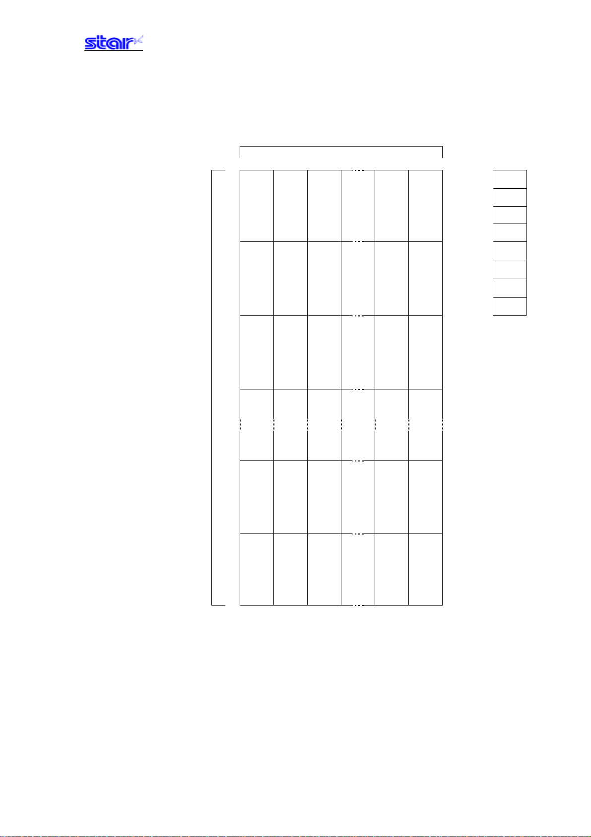
Relationships of logo and registered data
xn = xn1 + xn2 x 256 yn = yn1 + yn2 x 256
{(xn1 + xn2 x 256) x 8} dots
Data
MSB
d[11] d[21] d[n1]
(yn1 + yn2 x 256) bytes
(yn1 + yn2 x 256) x 8
d[12] d[22] d[n2]
dots
LSB
d[x1] d[x2] d[xn]
―――――――――――――――――――――――――――――――――――――――――― ――――――――――――――――――――――――――― ――――――――――――――――
STAR Line Mode Command Specifications 3-83
Page 100
ESC FS p n m
[Name] Print logo
[Code] ASCII ESC FS p n m
Hex. 1B 1C 70 n m
Decimal 27 28 112 n m
[Defined Area] 1≤n≤255
0≤m≤3
48≤m≤51 (”0”≤m≤”3”)
[Initial Value] - - [Function] Prints the logo of registration number n registered using the logo registration command (ESC FS
q) according to the print mode m.
m Logo print mode
0, 48 Normal mode
1, 49 Double wide mode
2, 50 Double high mode
3, 51 Double high/wide mode
If there is unprinted data in the line buffer, this command is executed after printing that data.
Therefore, it is not possible to print with other data in the same line (characters, bit images, bar
codes).
Form feed obeys the vertical print size of the logo.
Adornments other than upside-down printing and expansion settings are unaffected.
The horizontal printing start position conforms to the left margin position and the horizontal print
area conforms to the left and right margin settings.
If the logo horizontal print size exceeds the horizontal print region, the portion exceeding the area
is not printed.
<When using the 2 color print mode>
When the logo register number n is odd:
Register number n is printed in black; register number n + 1 is printed in red and overlapped.
The command is ignored when the capacity of the register number n and the capacity of the
register number n + 1 are different.
The command is ignored when the register number n = 255 is specified.
When the logo register number n is even:
Register number n is printed in black; register number n - 1 is printed in red and overlapped.
The command is ignored when the capacity of the register number n and the capacity of the
register number n - 1 are different.
The command is ignored when the register number n = 255 is specified.
―――――――――――――――――――――――――――――――――――――――――― ――――――――――――――――――――――――――― ――――――――――――――――
STAR Line Mode Command Specifications 3-84
 Loading...