

Page 1

OKIPAGE
4 /4
LED Page Printer
Maintenance Manual
OEL/INT
Approval
All specifications are subject to change without notice.
40245101TH
Page 2

HP, LaserJet and PCL5e are trademarks of Hewlett-Packard Co.
Page 3

PREFACE
This Maintenance Manual describes the field maintenance methods for LED Page Printers.
This manual is written for use by service persons. Please note that you should refer to the Printer
Handbook for the handling and operating methods of the equipment.
Page 4

CONTENTS
1. CONFIGURATION..................................................................................... 1 - 1
1.1 System Configuration ........................................................................ 1 - 1
1.2. Printer Configuration.......................................................................... 1 - 2
1.3 Option................................................................................................. 1 - 3
1.4 Specification ...................................................................................... 1 - 4
1.5 Safety Standards ............................................................................... 1 - 6
1.5.1 Certification Label.................................................................................... 1 - 6
1.5.2 Warning Label ......................................................................................... 1 - 6
2. OPERATION DESCRIPTION .................................................................... 2 - 1
2.1 Main Control Board............................................................................ 2 - 4
2.2 Power Supply Unit ............................................................................. 2 - 5
2.3 High-Voltage Power Supply Board .................................................... 2 - 5
2.4 Electro-Photographic Processor........................................................ 2 - 7
2.5 Electro-Photographic Process ........................................................... 2 - 11
2.5.1 Explanation of Each Process Operation.................................................. 2 - 13
2.6 Paper Jam Detection ......................................................................... 2 - 19
2.7 Toner Low Detection.......................................................................... 2 - 21
2.8 Cover Open ....................................................................................... 2 - 22
3. PARTS REPLACEMENT........................................................................... 3 - 1
3.1 Precautions for Parts Replacement................................................... 3 - 1
3.2 Parts Layout....................................................................................... 3 - 3
3.3 Replacing Parts ................................................................................. 3 - 6
3.3.1 Hopper Plate ........................................................................................... 3 - 6
3.3.2 LED Head and Head Spring.................................................................... 3 - 7
3.3.3 Transfer Roller.........................................................................................3 - 8
3.3.4 Upper Cover Assy ................................................................................... 3 - 9
3.3.5 High-Voltage Power Supply Board .......................................................... 3 - 10
3.3.6 Top Cover Assy and Flat Cable Assy...................................................... 3 - 11
3.3.7 Paper Holder ........................................................................................... 3 - 12
3.3.8 Side Plate M and Idle Gear ..................................................................... 3 - 13
3.3.9 Heat Assy ................................................................................................ 3 - 14
3.3.10 Drive Shaft E (Eject) and Eject Roller ..................................................... 3 - 17
3.3.11 Pressure Roller B (Back Up Roller)......................................................... 3 - 18
3.3.12 Separator Guide ...................................................................................... 3 - 19
3.3.13 Pulse Motor (Main) .................................................................................. 3 - 21
3.3.14 Hopping Shaft Assy ................................................................................. 3 - 22
3.3.15 Resist Roller ............................................................................................ 3 - 23
3.3.16 Paper Sensor E, Paper Sensor Exit and Toner Sensor Assy ................. 3 - 24
3.3.17 Base Plate ............................................................................................... 3 - 25
Page 5

4. ADJUSTMENT........................................................................................... 4 - 1
4.1 Adjustment Types and Functions ...................................................... 4 - 1
4.1.1 Printer Driver ........................................................................................... 4 - 1
4.1.2 Engine Maintenance Utility ...................................................................... 4 - 3
4.2 Adjustment When Replacing a Part................................................... 4 - 3
4.2.1 Setting LED Head Drive Time ................................................................. 4 - 3
4.2.2 Setting the LED Head Dot Count ............................................................ 4 - 4
4.2.3 Uploading and Downloading EEPROM Data .......................................... 4 - 5
5. PERIODICAL MAINTENANCE ................................................................. 5 - 1
5.1 Periodical Replacement Parts ........................................................... 5 - 1
5.2 Cleaning............................................................................................. 5 - 1
5.2.1 Cleaning of LED Lens Array .................................................................... 5 - 1
6. TROUBLESHOOTING PROCEDURES .................................................... 6 - 1
6.1 Troubleshooting Tips ......................................................................... 6 - 1
6.2 Check Points Before Correcting Image Problems ............................. 6 - 1
6.3 Notes When Correcting Image Problems .......................................... 6 - 1
6.4 Preparation Before Troubleshooting.................................................. 6 - 1
6.5 Troubleshooting................................................................................. 6 - 2
6.5.1 Status Monitor Message List ................................................................... 6 - 2
6.5.2 Status Message Troubleshooting ............................................................ 6 - 6
6.5.3 Image Troubleshooting ............................................................................ 6 - 13
7. WIRING DIAGRAM................................................................................... 7 - 1
7.1 Interconnect Signal Diagram ............................................................. 7 - 1
7.2 PCB Layout........................................................................................ 7 - 3
7.2.1 Main Control Board (HBMC-2 PCB)(OKIPAGE 4w plus) ........................ 7 - 3
7.2.2 Main Control Board (HBMC-3 PCB)(OKIPAGE 4m) ............................... 7 - 4
7.2.3 High-Voltage Power Sapply Board .......................................................... 7 - 5
8. PARTS LIST .............................................................................................. 8 - 1
APPENDIX A LOCAL PRINTING ............................................................... A - 1
APPENDIX B PARALLEL INTERFACE ..................................................... B - 1
APPENDIX C MACINTOSH INTERFACE................................................... C - 1
APPENDIX D MAINTENANCE UTILITY ..................................................... D - 1
Page 6

1. CONFIGURATION
Page 7
1. CONFIGURATION
1.1 System Configuration
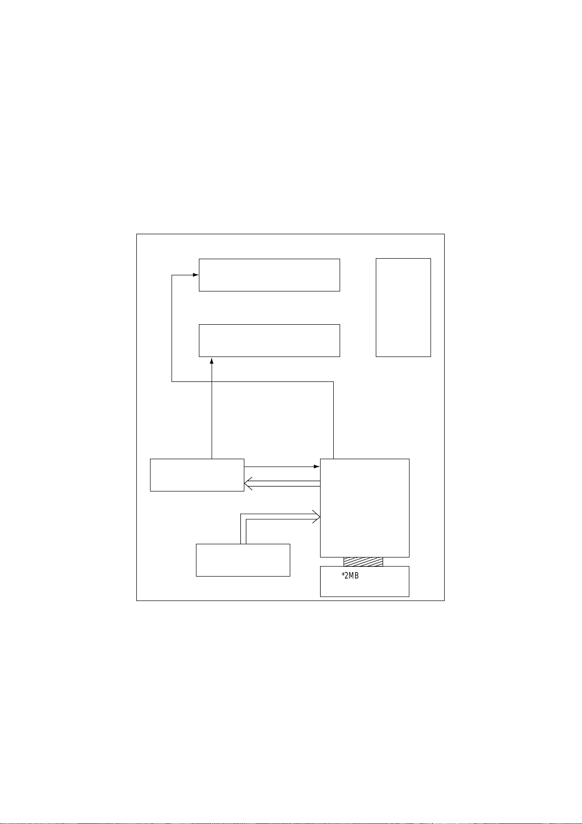
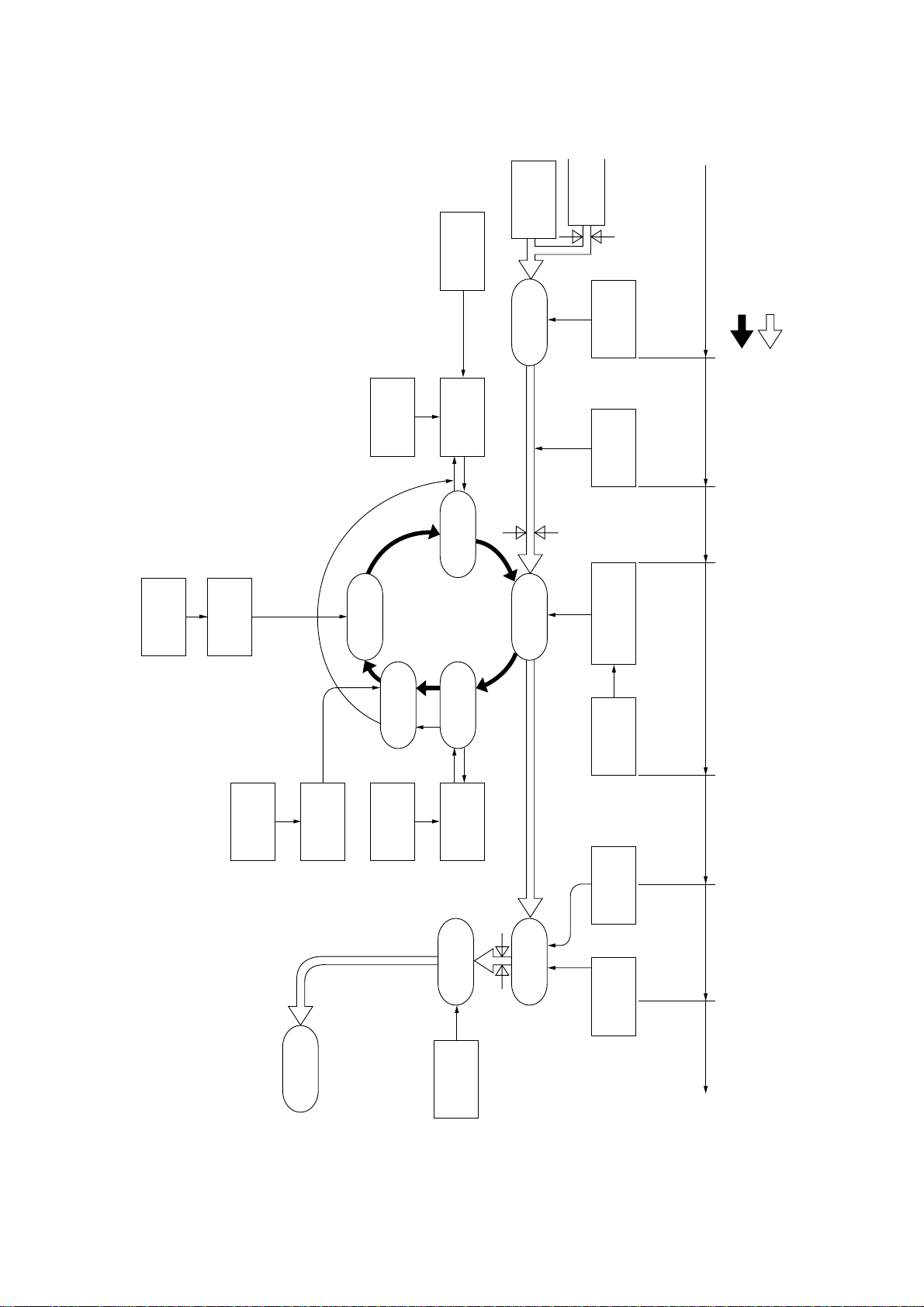
The OKIPAGE 4w Plus/4m consists of a control block, a power supply unit, and an engine block.
(See Figure 1-1.)
ENGINE UNIT
Paper Feed Mechanism
Hopper
Plate
Electro-photographic
Processor
High-Voltage Power
Supply Board
Power Supply Unit
Main Control Board
*2MB Memory
Expansion Board
*: Option (OKIPAGE 4m Only)
Figure 1-1
1 - 1
Page 8
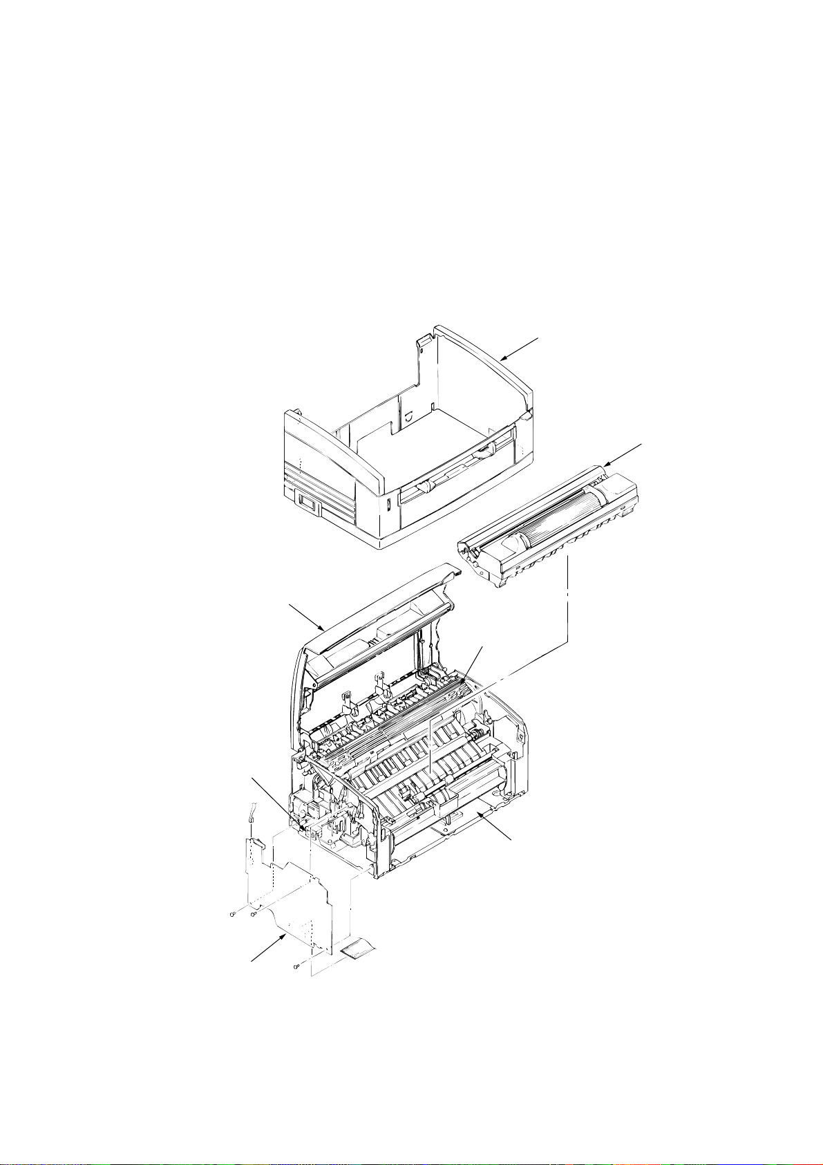
1.2 Printer Configuration
The printer unit consists of the following five hardware components:
• Electro-Photographic Processor
• Paper Feeder
• Main Control Board
• High-Voltage Power Supply Board
• Power Supply Unit
Figure 1-2 is the configuration of the printer unit.
Upper Cover Assy
EP Unit
Top Cover Assy
Power Supply Unit
High-Voltage Power
Supply Board
Heat Assy
Main Control Board
1 - 2
Page 9
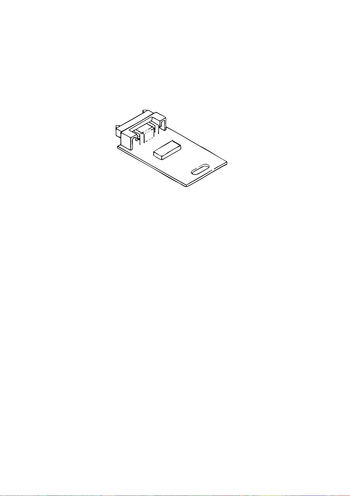
1.3 Option
(1) 2MB HBRB-PCB Option Memory Board(Only OKIpage 4m)
1 - 3
Page 10

1.4 Specification
(1) Type Desktop
(2) Outside dimensions Height 5.9” (150 mm)
(excludes protruding Width 12.2” (310 mm)
portion) Depth 7.5” (191 mm)
(3) Weight 3.8 kg
(4) Development method Dry non-magnetic development system
Exposure method LED stationary head
(5) Paper used <Type>
• Standard paper
– Xerox 4200 (20 lbs)
• Application paper (manual face-up feed)
– Label
– Envelope
– OHP paper (Transparency)
<Size>
14" (355.6 mm) (Max.) x 8.5" (215.9 mm)
<Thickness>
– Automatic feed: 16 to 28 lbs (60 to 90 g/m2)
– Manual feed: Label, Envelope, OHP paper (trans-
parency)
(6) Printing speed First print: 23 seconds (A4) (after warm-up)
Continuous print: 4 sheets/minute (A4)
Warm-up time: 40 seconds (120 VAC for ODA, 230
VAC for OEL/INT) (at room tempera-
ture 77 ˚F (25 ˚C))
(7) Paper feeding method Automatic paper feed or manual paper feed
(8) Paper delivery method Face down
(9) Resolution 300 dpi x 300 dpi, 600 dpi x 600 dpi (quasi)
(10) Power input 230 VAC +15%, -14% (for OEL/INT)
120 VAC +6%, -15% (for ODA)
(11) Power consumption Peak: 450W
Typical operation: 100W
Idle: 30W
Power save mode: 5W
1 - 4
Page 11

(12)Temperature and humidity
Humidity
During operation
In storage
Caution:
Temperature and humidity in storage are measured with the OKIPAGE 4w plus/4m
being packed; they are valid for one year.
Temperature
10 to 32 ˚C
–10 to +43 ˚C
20 to 80% RH (relative humidity)
10 to 90% RH (relative humidity)
No condensation is permissible.
(13)Noise During operation: 48 dB (A) or less
Standby: 38 dB (A) or less
(14)Consumables Toner cartridge kit 1,000 (5% duty)
Image drum cartridge 10,000 (at continuouts printing)
1 - 5
Page 12
1.5 Safety Standards
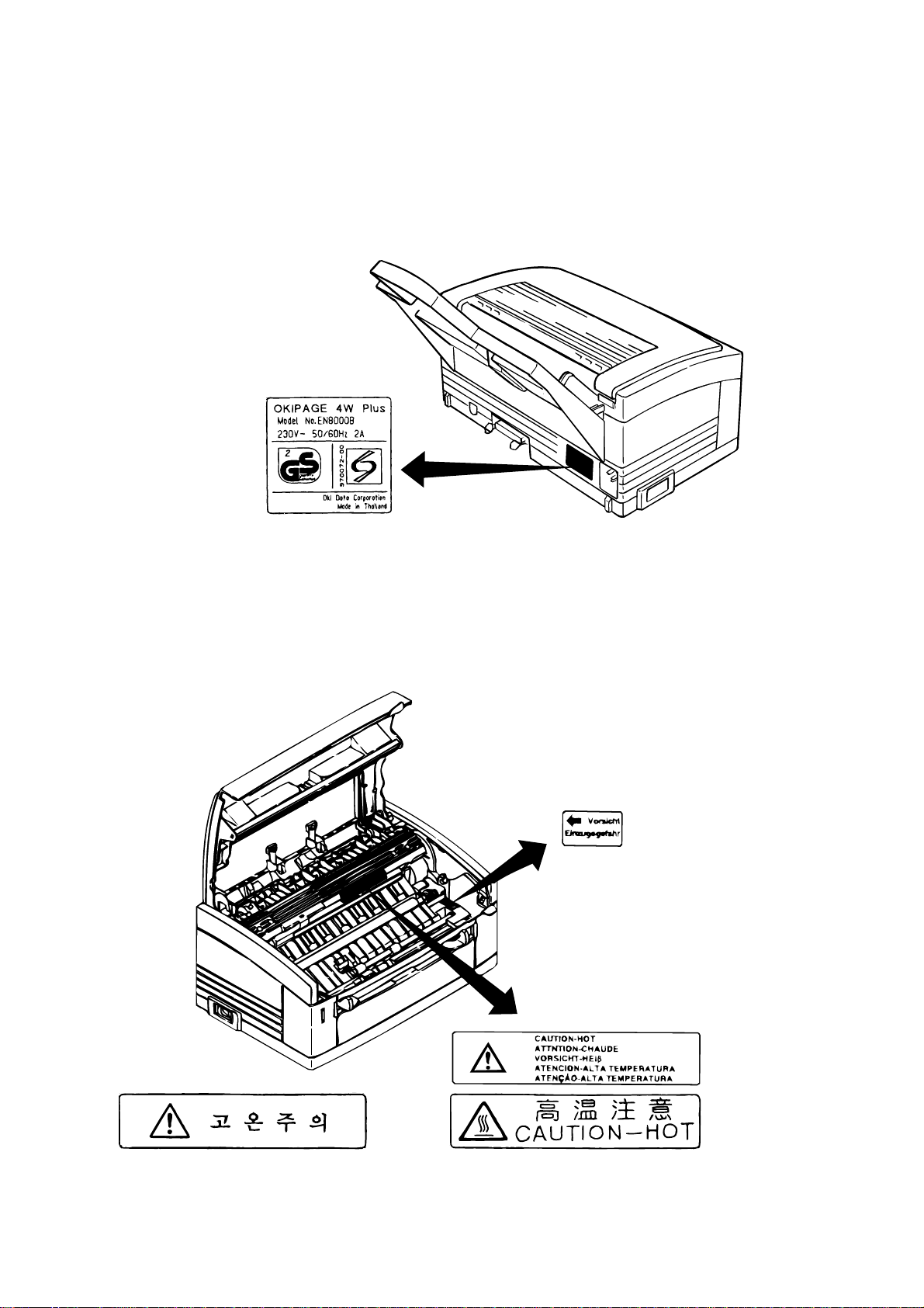
1.5.1 Certification Label
The safety certification label is affixed to the following location of the OKIPAGE 4w:
OKI-INT
4w Plus
1.5.2 Warning Label
Warning labels are affixed to the locations that may cause bodily injury.
During maintenance, do work with enough care while following instructions on these warning
labels.
For OEL
1 - 6
For OEL, OKI-INT
For China, TAIWANFor Korea
Page 13

2. OPERATION DESCRIPTION
Page 14

2. OPERATION DESCRIPTION
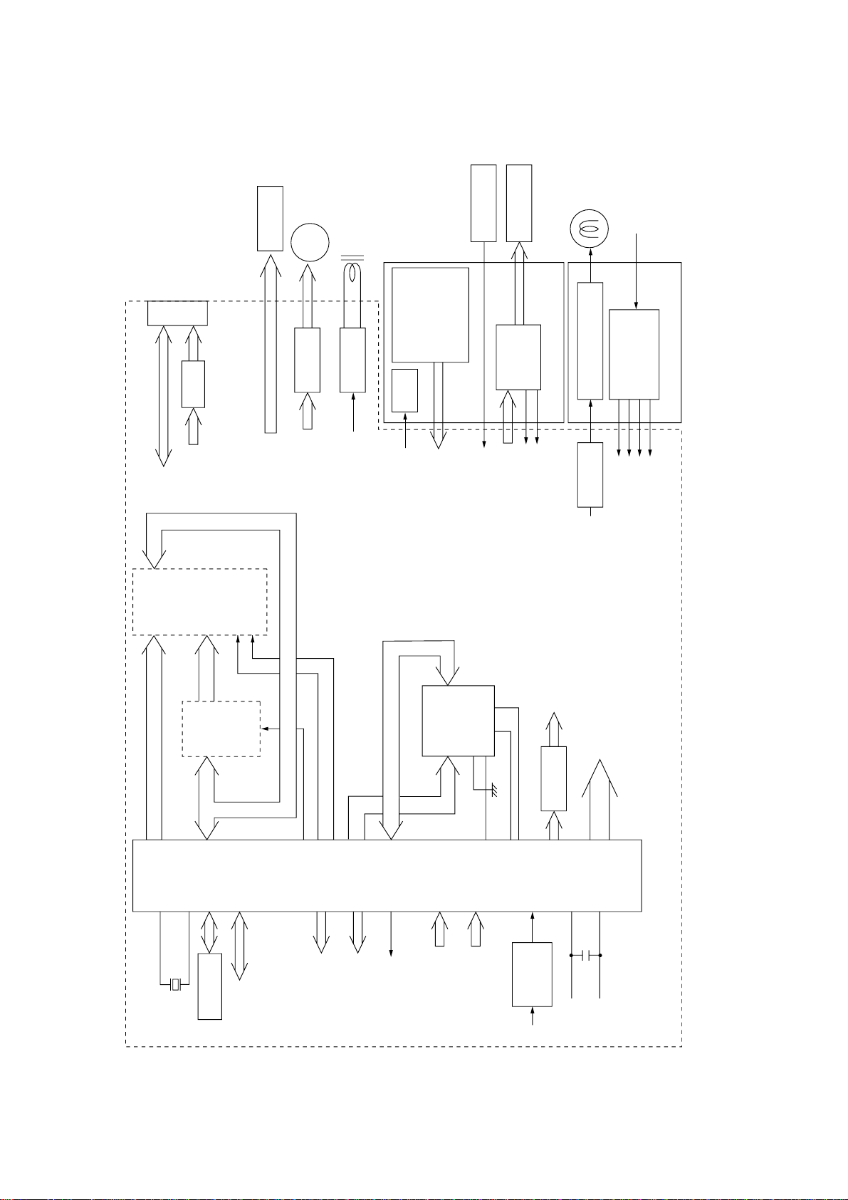
The OKIPAGE 4w Plus/4m consists of a main control board, a high-voltage power supply board,
a power supply unit, and an electro-photographic processor. The OKIPAGE 4w Plus/4m receives
print data from a higher-level interface and sequentially stores it in memory. The OKIPAGE 4w
Plus/4m decodes and edits the received data while storing print data from the interface in
memory. It sequentially transfers the edited data to the LED head for each dot line. The electrophotographic processor then prints the data on sheets of paper.
The display of the higher-level host is used for device operation and status display.
Figure 2-1 is the block diagram of the OKIPAGE 4w Plus/4m.
2 - 1
Page 15
EEPROM
Parallel
I/F
LED head
Main motor
Electromagnetic
clutch
Sensors
TEMP
TR-VSEN
TR-ISEN
Reset
circuit
10 MHz
MSM65917
(nX-8 core)
Address
latch
EPROM
(52 KByte)
OE
CS
A8 ~ A15
AD0 ~ AD7 A0 ~ A7
D0 ~ D3
A0 ~ A10
D0 ~ D7
D-RAM
(512 KB: For INT)
(128 KB: For OEL)
Driver High-voltage power I/F
LED
HEAT ON
5V
5V
OVL
CN
Parallel
I/F
Parallel
I/F
LED head
Main motor
Electromagnetic
clutch
LS07
Driver
Main motor
Electromagnetic
clutch
LED head
Driver
Driver
AC output ON/OFF
Switching
power supply
<Power Supply Unit>
<Main Control Board>
<High-voltage Power Supply Board>
LED
Thermistor
EP cartridge
Heater
(Halogen lamp)
AC
(120 V/230 V)
Manual feed sensor
Paper sensor
Outlet sensor
Toner sensor
Cover open switch
LED
Sensors
TEMP
High-voltage
power I/F
TR-VSEN
TR-ISEN
HEAT ON
+24 V
+5 V
0VL
0VP
M
High voltage
power
supply
Figure 2-1 Block Diagram (OKIPAGE 4w Plus)
2 - 2
Page 16

EEPROM
Parallel
I/F
LED head
Main motor
Electromagnetic
clutch
Sensors
TEMP
TR-VSEN
TR-ISEN
Reset
circuit
10 MHz
MSM65917
(nX-8 core)
Address
latch
EPROM
(52 KByte)
OE
CS
A8 ~ A15
AD0 ~ AD7 A0 ~ A7
D0 ~ D3
A0 ~ A10
D0 ~ D7
D-RAM
(512 KByte)
D-RAM
(2 MByte)
Driver High-voltage power I/F
LED
HEAT ON
5V
5V
OVL
CN
Parallel
I/F
Parallel
I/F
LED head
Main motor
Electromagnetic
clutch
LS07
Driver
Main motor
Electromagnetic
clutch
LED head
Driver
Driver
AC output ON/OFF
Switching
power supply
<Power Supply Unit>
<Main Control Board>
<High-voltage Power Supply Board>
LED
Thermistor
EP cartridge
Heater
(Halogen lamp)
AC
(120 V/230 V)
Manual feed sensor
Paper sensor
Outlet sensor
Toner sensor
Cover open switch
LED
Sensors
TEMP
High-voltage
power I/F
TR-VSEN
TR-ISEN
HEAT ON
+24 V
+5 V
0VL
0VP
M
High voltage
power
supply
option
Driver IC
Mac I/F
(Option RAM-PCB)
Figure 2-1 Block Diagram (OKIPAGE 4m)
2 - 3
Page 17

2.1 Main Control Board
The main control board consists of a one-chip CPU, a program ROM, a DRAM, an EEPROM, a
host interface circuit, and a mechanism driving circuit. The mechanism driving circuit consists of
a LED head, a main motor, and an electromagnetic clutch.
(1) One-chip CPU
The one-chip CPU is a custom CPU (8-bit internal bus, 8-bit external bus, 10-MHz clock)
incorporating mask ROM and CPU peripheral devices. This CPU has the functions listed in
the table below.
Built-in Device Function
DRAM controller
DMA controller
Parallel interface controller
Video output port
LED STB output port
Timer
I/O port
A/D converter
(2) Program ROM
Program ROM contains a program for the equipment. EPROM is used as program ROM.
When mask ROM in the one-chip CPU explained in (1) above is valid, the EPROM is not
mounted. (For details on short wiring setting, see Section 7.2.)
(3) DRAM
DRAM is used as resident memory.
Controls DRAM.
Transfers image data from Parallel I/F to DRAM, from DRAM to a video output port and
between CPU and DRAM.
Controls the parallel interface.
Controls LED head.
Generates various control timings for monitoring paper feeding and a paper size.
Inputs and outputs the sensor signals and motor signals, etc.
Also performs I/O for EEPROM.
Inputs the feedback signals from a high-voltage generation circuit and thermistor signal.
(4) EEPROM
EEPROM holds the following data:
• Menu data
• Counter value
• Adjustment value
(5) Parallel interface
The parallel interface receives parallel data from the host; it conforms to the IEEE1284
specification.
(6) Macintosh interface <only OKIPAGE 4m>
Mcintosh interfacce receives serial data from the host ; it conforms to the IEEE1284.
2 - 4
Page 18

2.2 Power Supply Unit
The power supply unit supplies +5 V and +24 V to the main control board according to 230 VAC
/120 VAC.
Output voltage Application
+5 V
+24 V
Used to generate a logic circuit and a high voltage.
Used to drive the motor and electromagnetic clutch.
The power supply unit also contains a heater drive circuit.
2.3 High-Voltage Power Supply Board
(1) High-Voltage power supply circuit
The high-voltage power supply circuit generates the following voltages required for the
electro-photographic processor from +5 V according to the control sequence from the main
control board. When the cover is open, +5 V supply is automatically interrupted to stop high-
voltage output.
Output Application
CH
–1.35 KV
DB
–300 V/+300 V
SB
–450 V/ 0 V
CB
+400 V
TR
+500 V ~ +3.5 KV/–750 V
Voltage
Voltage to be applied to a charge roller.
Voltage to be applied to a developing roller.
Voltage to be applied to a sponge roller.
Voltage to be applied to a cleaning roller.
Voltage to be applied to a transfer roller.
Caution:
The TR voltage varies with medium and transfer roller impedance.
2 - 5
Page 19
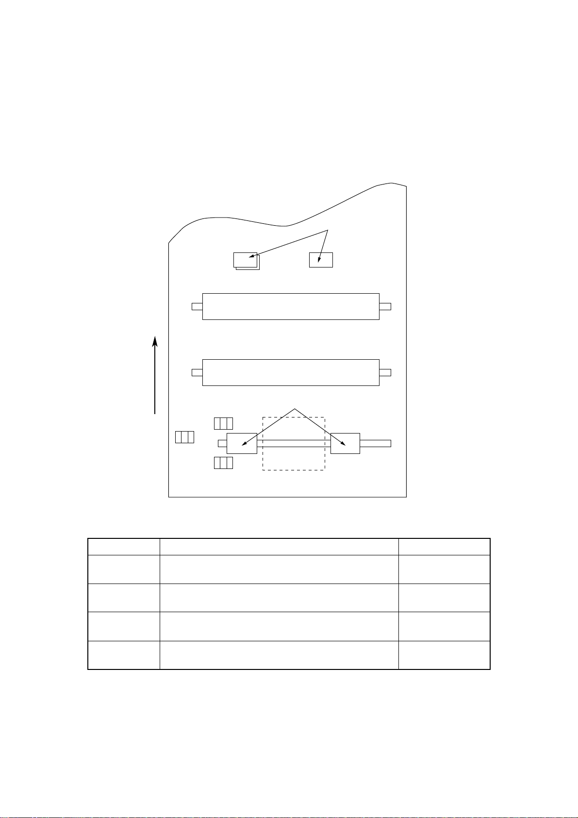
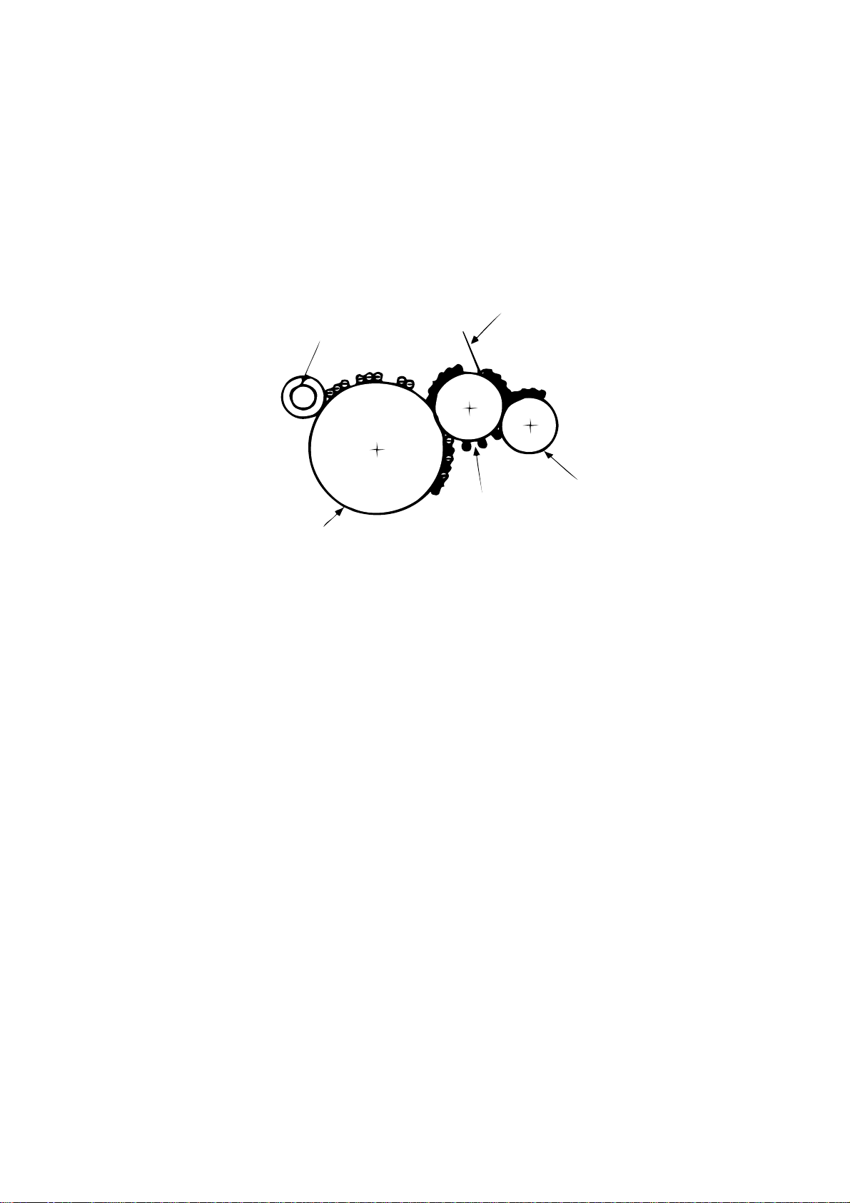
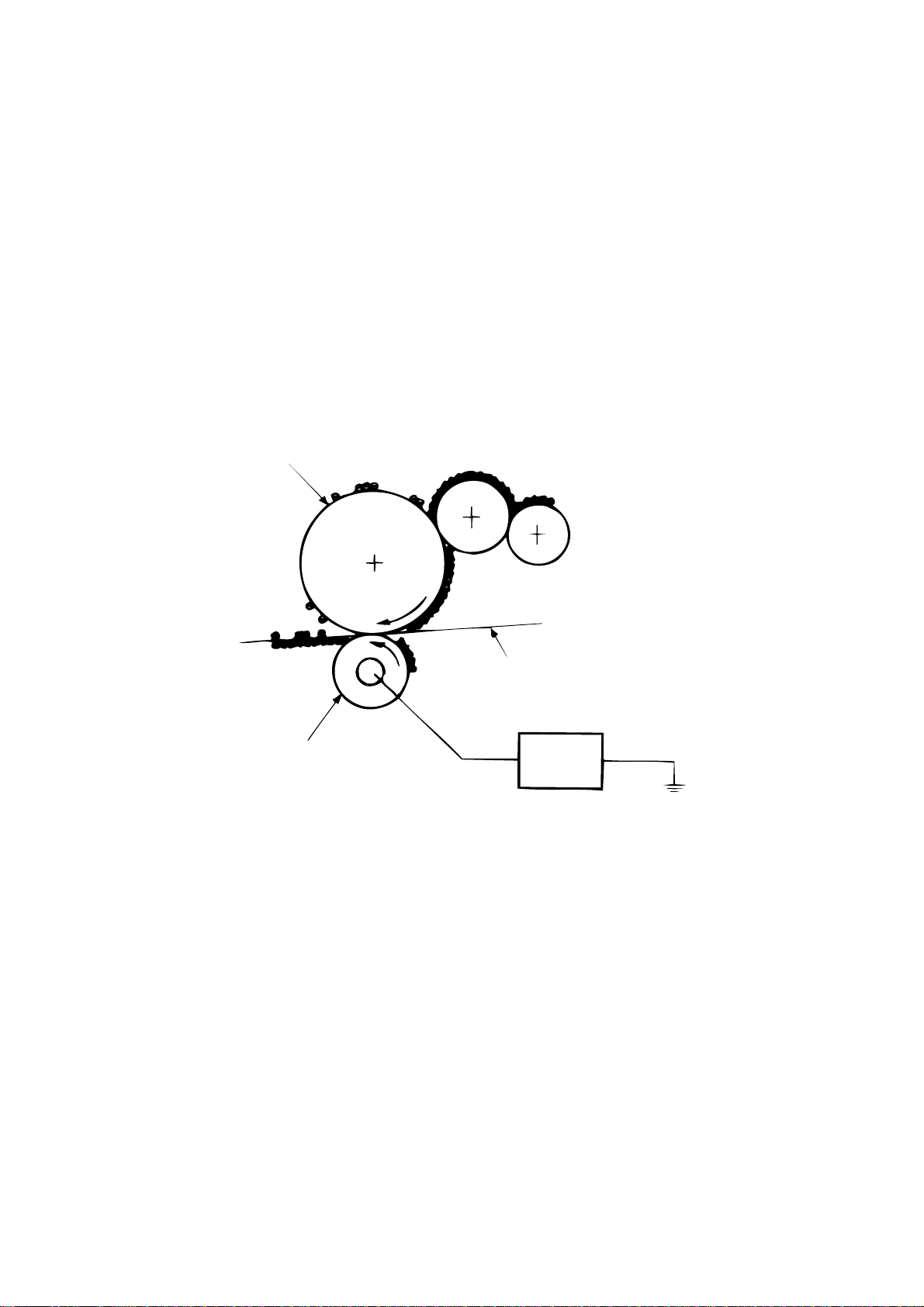
(2) Sensors
The high-voltage power supply board consists of the high-voltage power supply circuit that
supplies power to the electro-photographic processor system and the photosensor that
detects a paper feeding system and toners.
Figure 2-2 shows the sensor layout drawing.
Exit roller
Outlet sensor
Heat roller
Transfer roller
Paper sensor
Toner
sensor
assy
Manual feed sensor
Paper feeding direction
Feed roller
Hopping
roller
Figure 2-2
Sensor Function Sensing State
Manual feed
sensor
Paper sensor
Outlet sensor
Toner sensor
Monitors whether paper was inserted into the manual feed sensor
section.
Detects the leading part of the paper.
Monitors paper feeding.
Monitors paper feeding and the paper size according to the paper
sensor arrival and passing time.
Detects the low toner status.
ON: Paper exists.
OFF: No paper exists.
ON: Paper exists.
OFF: No paper exists.
ON: Paper exists.
OFF: No paper exists.
ON (long): Toner low
OFF (short): Toner High
2 - 6
Page 20

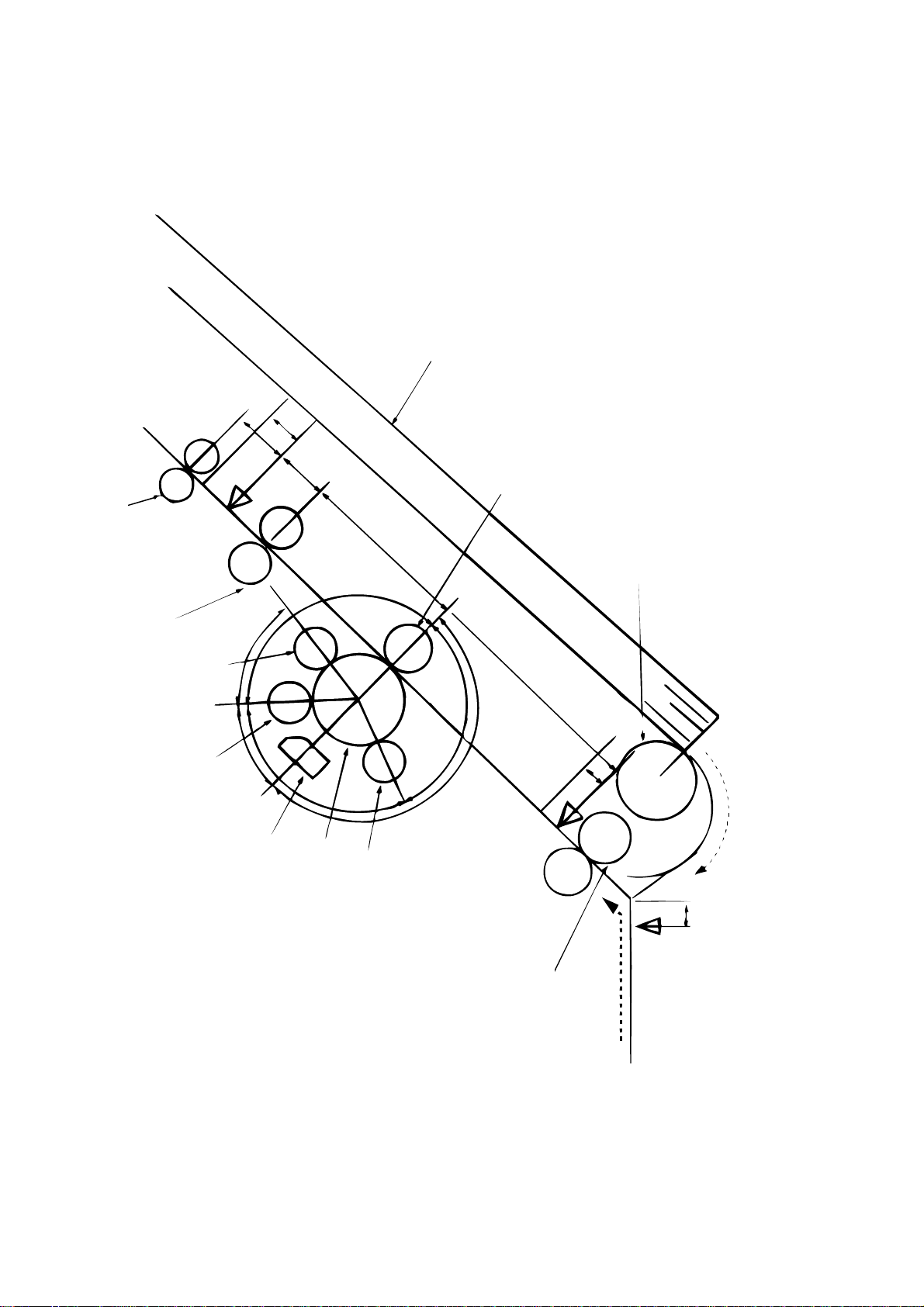
2.4 Electro-Photographic Processor
The electro-photographic processor prints out the image data to be sent from the main control
board on sheets of paper. Figure 2-3 shows the layout drawing of the electro-photographic
processor.
(1) Image drum unit
The image drum unit makes a toner adhere to the formed electrostatic latent image with static
electricity. This electrostatic latent image is formed by the lights irradiated from LED heads.
(2) Electromagnetic clutch
The electromagnetic clutch controls the rotation of the hopping roller according to signals
from the control block.
2 - 7
Page 21
Exit roller
Heat roller
(ø 19.910)
6.85
10
OFF
ON
26.50
Outlet sensor
Cleaning roller
(ø 9.000)
Charge roller
(ø 9.000)
6.77
LED head
Drum roller
(ø 16.000)
Developing roller
(ø 14.000)
17.23
12.72
23.18
20.32
64.60
Single tray
Transfer roller
(ø 15.000)
Hopping roller
OFF
32.00
10
Tray printing
10
ON
OFF
Manual feed sensor
Manual
printing
Feed roller
Paper sensor
2 - 8
Figure 2-3 Layout Drawing of Electro-Photographic Processor
Page 22

(3) Pulse motor (Main)
This pulse motor of 48 steps/rotation is two-phase excited by the signal from the main control
board; it performs feeding control by switching normal rotation to reverse rotation or vice
versa and turning on/off the electromagnetic clutch. The relationship between the main
motor, electromagnetic clutch, resist gear, drum gear, hopping roller is shown in the table
below and on the subsequent pages.
Main Motor Electromagnetic Clutch
Normal rotation
Reverse rotation
OFF
ON
OFF
Hopping Roller
Non-rotation
Rotation
Non-rotation
Regist Gear Drum Gear Operation
Non-rotation
Rotation
Rotation
Rotation
Rotation
Rotation
Warm-up
Hopping
Prinitng
(4) LED head
The shift and latch registers receive image data from the main control board for each dot line.
2,560 or 2,496 LEDs are driven to radiate the image drum.
(5) Heat Assy
The heat Assy consists of a heater, a heat roller, a thermistor, and a thermostat.
The power supply unit supplies AC voltage to the heater according to the HEATON signal
from the main control board to heat the heat roller. The main control board monitors the heat
roller temperature via the thermistor and keeps the temperature constant by turning on/off
the heater AC voltage supply.
If the heat roller temperature rises abnormally, the thermostat of the heater voltage supply
circuit functions to forcibly suspend the AC voltage supply.
2 - 9
Page 23
Exit roller
Heat roller
Transfer roller
Cleaning roller
CH roller
Drum roller
Developing roller
Outlet
sensor
Paper sensor
Hopping roller
TRAY printing
Feed roller
Manual
feed
sensor
Manual printing
2
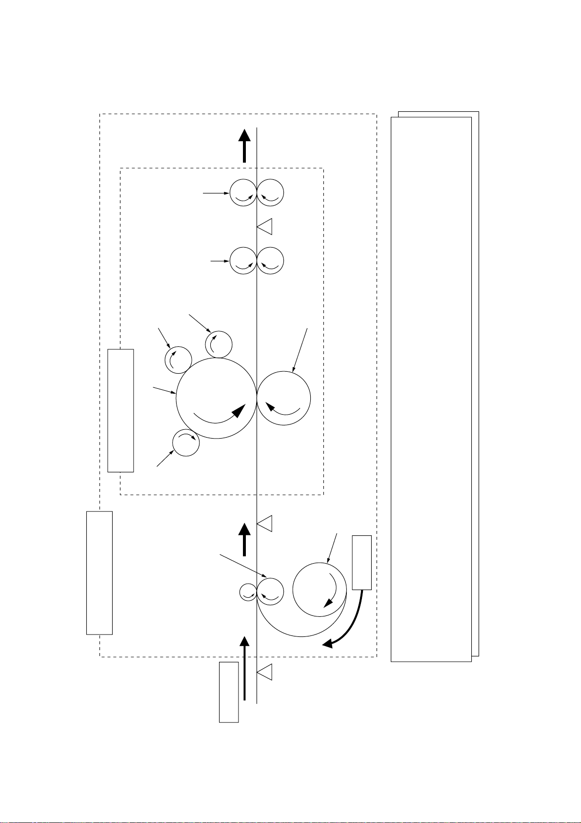
Roller to be driven by reverse
rotation of pulse motor (Main)
1
Motor to be driven by normal
rotation of pulse motor (main)
Roller control by pulse motor (main)
1
Normal rotation of pulse motor (main): Drum roller, transfer roller, cleaning roller, CH roller, developing roller, heat roller, exit roller rotation
2
Reverse rotation of pulse motor (main): Drum roller, transfer roller, cleaning roller, CH roller, developing roller, heat roller, exit roller, feed roller,
hopping roller rotation
Hopping operation from the tray, however, is performed when the electromagnetic clutch is turned on.
Figure 2-4 Schematic Drawing of OKIPAGE4w Plus/4m Paper Feeding
2 - 10
Page 24

2.5 Electro-Photographic Process
(1) Electro-photographic process
The electro-photographic process is outlined below.
1 Charging
The surface of the OPC drum is charged negatively and uniformly by applying the DC
voltage to the CH roller.
2 Exposure
Light emitted from the LED head irradiates the negatively charged surface of the OPC
drum. The surface potential of the irradiated surface attenuates to form the electrostatic
latent image corresponding to the image signal.
3 Development and residual toner recovery
The negatively charged toner is brought into contact with the OPC drum, adhering to the
electrostatic latent image on the OPC drum by static electricity. This adhesion causes
the electrostatic latent image to change to a visible image.
At the same time, the residual toner on the OPC drum is attracted to the developing
rollerby static electricity.
4 Transfer
When paper is placed over the image drum surface, the positive charge which is
opposite in polarity to that of the toner, is applied to the reverse side by the transfer roller.
The toner is attracted by the positive charge and is transferred onto the paper. This
results in the transfer of the toner image formed on the image drum onto the paper.
5 Cleaning
The cleaning roller temporarily attracts the residual toner on the transferred OPC drum
with static electricity, then returns the toner to the OPC drum.
6 Fusing
The transferred unfused toner image is fused to a sheet of paper by applying heat and
pressure to the image.
Figure 2-5 is a flow for the electro-photographic process.
2 - 11
Page 25
Paper
holder
section
Manual feed
Control signal
LED head
Power
supply
Exposure
Toner
cartridge
roller
Developing
Paper
supply
Transfer
Manual feed
roller
Hopping
Feed roller
Paper sensor
Transfer roller
sensor
: OPC drum rotation direction
: Paper feeding path
Power
supply
roller
Charge
Paper delivery
Charging
Power
supply
Cleaning Development
roller
Cleaning
Paper feeding
Outlet sensor
roller
Paper eject
Fusing
Power
supply
roller
Back-up
Heat roller
Figure 2-5 Flow for Electro-Photographic Process
Paper ejection Fusing Cleaning Transfer Development Paper feed Paper hopping
2 - 12
Page 26
2.5.1 Explanation of Each Process Operation
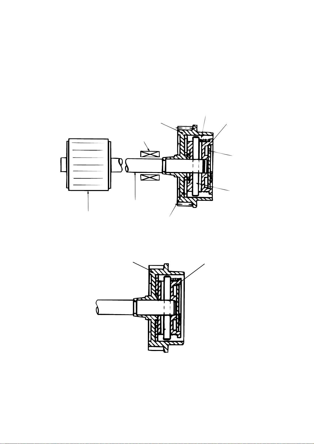
(1) Hopping
As shown in the figure below, the clutch for hopping is turned on/off according to current ON/
OFF to a coil.
When the clutch is OFF
Coil
Hopping gear
Spring for resetting
Clutch plate
Magnetic
substance plate
Pin
Hopping roller
When the clutch is ON
Hopping shaft
Hopping gear
Engagement section
Clutch plate
When the clutch is on, the hopping gear engages with the clutch plate to rotate the hopping
roller.
When the clutch is off, the hopping gear is separated from the clutch plate by the spring for
resetting, disabling the rotation of the hopping roller.
2 - 13
Page 27
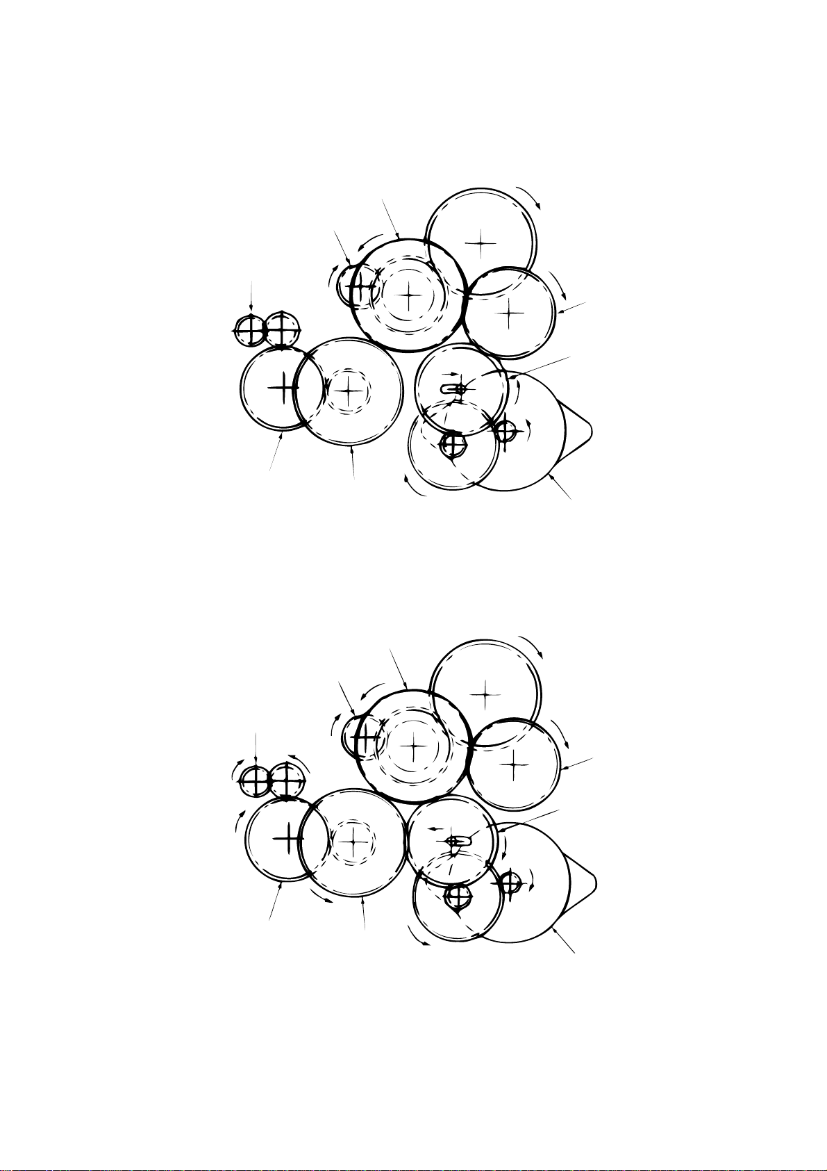
(2) Printing and warm-up
At warm-up
Triple gear
Transfer gear
Resist gear
Idle gear
Planetary gear
a
Pulse motor (main)
Hopping gear
a"
a'
Gear A
Rotate the pulse motor (main) in the a direction. The planetary gear rotates in the a’ direction,
dislocating its position in the a” direction. This causes the planetary gear to be separated from
gear A. The hopping gear will not rotate. The triple gear and transfer gear rotate via the idle
gear to drive the EP unit.
At printing
Transfer gear
Resist gear
Hopping gear
Triple gear
b"
b'
Gear A
The paper is further advanced in synchronization to the print data.
Idle gear
Planetary gear
b
Pulse motor (main)
2 - 14
Page 28
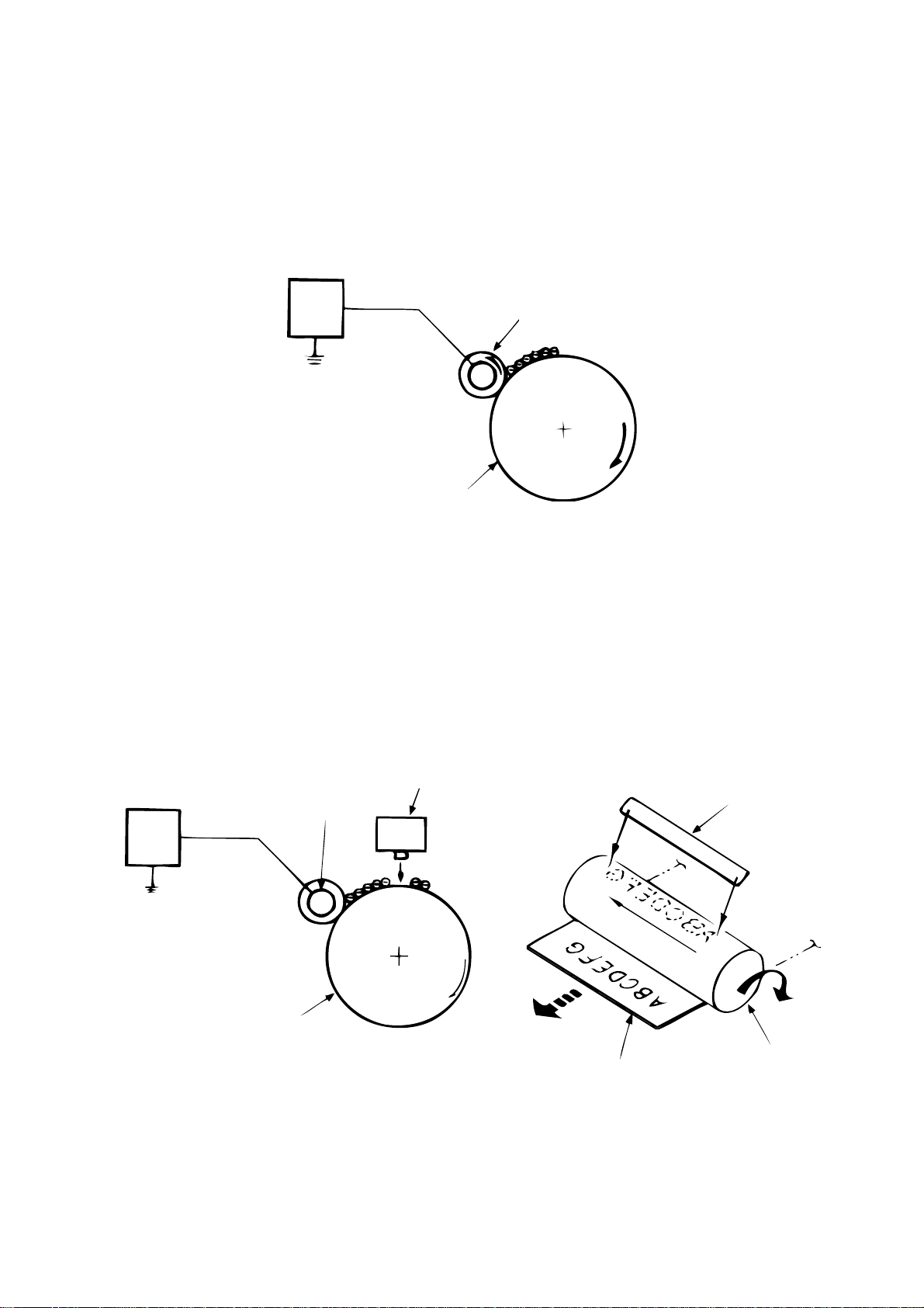
(3) Charging
Charging is performed by applying DC voltage to the charge roller that is in contact with the
surface of the OPC drum.
High-
voltage
power
supply
OPC drum
Charge roller
(4) Exposure
High-
voltage
power
supply
Light emitted from the LED head irradiates the negatively charged surface of the OPC drum.
The surface potential of the irradiated surface attenuates to form the electrostatic latent
image corresponding to the image signal.
LED head
Charge roller
OPC drum
LED head
2 - 15
Paper
OPC drum
Page 29
(5) Development
The electrostatic latent image on the surface of the OPC drum is changed to a visible toner
image by applying a toner to it. Development is performed in the contact part between the
OPC drum and developing roller.
1 The sponge roller negatively charges a toner and applies it to the developing roller.
Developing blade
Charge roller
Sponge roller
Developing roller
OPC drum
2 The toner applied to the developing roller is thin-coated by the developing blade.
3 A toner adheres to the exposure part of the OPC drum in the contact part between the
OPC drum and developing roller. This causes the electrostatic latent image to be
changed to a visible image.
2 - 16
Page 30
(6) Transfer
The transfer roller is composed of conductive sponge material. This roller is set so that the
surface of the OPC drum and sheets of paper will adhere closely.
A sheet of paper is placed on the surface of the OPC drum and the positive charge opposite
to the negative charge of a toner is applied from the reverse side by the transfer roller.
When a high negative voltage is applied from the power supply to the transfer roller, the
positive charge induced on the surface of the transfer roller moves to the paper side at the
contact part between the transfer roller and the sheet of paper. The positive charge on the
lower side of the sheet of paper then causes the negatively charged toner adhering to the
surface of the OPC drum to move to the upper side of the sheet. This enables transfer to the
sheet of paper.
OPC drum
Transfer roller
Paper
High-voltage
power supply
2 - 17
Page 31

(7) Fusing
The transferred unfused toner image is fused to a sheet of paper because heat and pressure
are applied when it passes between the heat roller and back-up roller.
The Teflon-coated heat roller contains a 400 W heater (Halogen lamp) that heats the heat
roller. The thermistor on the surface of the heat roller keeps the temperature of the heat roller
constant. A thermostat is also installed for safety. If temperature rises abnormally, this
thermostat opens to suspend voltage supply to the heater.
The back-up roller is pressurized to the heat roller by the pressure spring on each side.
Thermistor
Separation claw
Heat roller
Heater
Back-up roller
Pressure spring
(8) Cleaning
After transfer has terminated, the cleaning roller temporarily draws in the untransferred
residual toner adhering to the OPC drum with static electricity and then returns it to the OPC
drum.
OPC drum
Cleaning roller
High-voltage
power supply
Transfer roller
2 - 18
Page 32

2.6 Paper Jam Detection
The OKIPAGE 4w Plus/4m monitors the paper status when the power supply is on and during
printing. In the following cases, the OKIPAGE 4w Plus/4m interrupts the printing process as a
paper jam. Printing can be recovered by opening the cover, removing the jammed paper, and
closing the cover.
Error
Cause of Error
Paper inlet jam ••Only the manual feed sensor detects "Paper exists" when the power supply is on.
The leading part of the paper does not reach the paper sensor although hopping
operation was performed three time.
Paper feed jam • The leading part of the paper does not reach the outlet sensor within a fixed time after it
has passed the paper sensor.
Paper outlet jam • The trailing part of the paper does not pass the outlet sensor within L mm after the
leading part of the paper has passed the outlet sensor.
2.52" (64 mm) L 15.77" (400.6 mm)
<=<
=
Paper size error • The trailing part of the paper does not pass the paper sensor within L mm after the
leading part of the paper has passed the paper sensor.
2.52" (64 mm) L 15.77" (400.6 mm)
<=<
=
Error
Type of Error
Supervisory Sensor
Reference Value
Pluse Minus
Paper feed error
Paper feed jam1
Paper size error
Paper outlet jam
Paper feed jam 2
Electromagnetic clutch ON/
Paper sensor ON
Paper sensor ON/
Outlet sensor ON
Paper sensor ON/
Paper sensor OFF
Outlet sensor ON/
Outlet sensor OFF
Paper end sensor OFF/
Outlet sensor OFF
2 - 19
69.8
122.9
2.52" (64 mm) L
<=<
=
15.77" (400.56 mm)
2.52" (64 mm) L
<=<
=
15.77" (400.56 mm)
121.9
35
20.0
—
45.0
20.0
—
—
—
45.0
20.0
Unit: mm
Page 33

Pulse motor
(main)
Normal
rotation
OFF
Reverse
rotation
Electromagnetic
clutch
Manual feed
sensor
Paper sensor
Outlet sensor
Operation mode
OFF
ON
OFF
ON
OFF
ON
OFF
ON
Warm-up Paper feed Printing
Timing Chart for Paper Feed (Tray Feed)
2 - 20
Page 34

Paper Feed Check List
2.7 Toner Low Detection
• Hardware configuration of toner sensor
The figure below shows the hardware configuration of the toner sensor.
Photointerrupter
Image drum unit
Agitation bar (iron)
Magnet
Toner sensor lever
Hardware Configuration of Toner Sensor
• Toner detection method
(1) Toner sensor monitoring conditions are shown in the figure below.
Toner sensor
Magnet draw-in
t1
T
Caution:
The toner sensor is not monitored when the drum is inactive.
(a) When the toner-low state continues twice, Toner Low occurs. (This state is monitored
at a cycle of 40 milliseconds.)
(b) When the toner-full state continues twice, Toner Low is released. (This state is
monitored at a cycle of 40 milliseconds.)
(c) When the toner sensor does not change over two cycles (T x 2), the toner sensor
alarm state occurs.
(d) After the EP unit has been replaced (after the drum counter has been reset), Toner
Low is not detected when the drum counter indicates 1 to 100 counts.
2 - 21
Page 35

(2) The basic rotation cycle of the toner sensor is as follows:
2.8 Cover Open
Opening the stacker cover turns off the microswitch on the high-voltage power supply board to
suspend +5 V supply to the high voltage power supply. This results in the stop of all high-voltage
outputs. At the same time, the CVOPN signal is issued to notify the main control board of the
switch status and cover open processing is executed.
Basic rotation cycle of toner sensor
Toner low time
Toner full time
T time
4.9 sec.
t1 > 1.2 sec.
1.2 sec. > t1 > 0.28 sec.
2 - 22
Page 36

3. P ARTS REPLACEMENT
Page 37

3. PARTS REPLACEMENT
This chapter explains how to replace parts, assemblies, and units in the field.
The replacement procedures to be explained here include dismounting, not mounting. When
mounting parts, assemblies, and units, reverse the dismounting steps.
3.1 Precautions for Parts Replacement
(1) Be sure to dismount the AC cord and interface cable before replacing parts.
(a) Be sure to dismount the AC cord in the following procedures:
i) Turn off the POWER switch of the printer (“0“).
ii) Disconnect the AC inlet plug of the AC cord from the AC receptacle.
iii) Disconnect the AC cord and interface cable from the printer.
(b) Be sure to reconnect the printer in the following procedures:
i) Connect the AC cord and interface cable to the printer.
ii) Connect the AC inlet plug to the AC receptacle.
iii) Turn on the POWER switch of the printer (“|”).
Dismounting
OFF
ON
(2) Do not disassemble parts as long as the printer is operating normally.
(3) Minimize disassembling. (Only the parts indicated in the parts replacement procedures can
be dismounted.)
(4) Use only the specified maintenance tools.
(5) Disassemble parts in the specified sequence; otherwise, parts may be damaged.
(6) Temporarily tighten small parts such as screws and collars to the original locations because
they tend to be lost easily.
Reconnection
(7) When handling ICs such as CPUs, ROM, and RAM and PC boards, do not wear gloves that
easily cause static electricity.
(8) Do not place PC boards directly on devices and floors.
3 - 1
Page 38

[Maintenance Tools]
Table 3-1 lists the maintenance tools necessary for parts replacement.
Table 3-1 Maintenance Tools
No.
1
2
3
4
5
6
7
No. 1-100 Philips
screwdriver
No. 2-100 Philips
screwdriver
No. 3-100 Philips
screwdriver
No. 5-200 screwdriver
Digital multimeter (tester)
Pliers
Handy cleaner
Q'ty Use RemarksMaintenance Tools
1
1
1
1
1
1
1
2~2.5 mm screw
3~5 mm screw
[Maintenance Utility]
No.
1
Table 3-2 Maintenance Utility
Q'ty Use RemarksMaintenance Utility
Maintenance utility
1
3 - 2
Page 39

3.2 Parts Layout
This section explains the layout of main parts.
[Upper Cover Assy]
Hopper plate
Spur gear (A)
Guide slide (R)
Guide slide (L)
Upper cover
Figure 3-1
3 - 3
Page 40

[Base Frame Unit]
Top cover assy
Paper guide (R)
LED head
Pressure roller (B)
(Back up roller)
Flat cable assy
Head spring
Heat assy
Paper guide (L)
Hopper
spring
Stopper spring
Transfer roller
Paper
holder
Resistration roller
Drive shaft E (eject)
Idle gear heat
Roller holder
Tension
plate
Slide plate M
Hopping
shaft
Magnet H
(hopping shaft)
assy
High-voltage power
supply board
Sheet guide
Figure 3-2
3 - 4
Hopping roller
Toner
Pulse motor
(main)
Power sensor E
cartridge
unit
EP unit
Page 41

[Base Plate Unit]
Power supply unit
Main control board
Figure 3-3
3 - 5
Base plate assy
Page 42

3.3 Replacing Parts
This section explains how to replace parts and assemblies.
3.3.1 Hopper Plate
(1) Remove two claws and dismount hopper plate 1.
1
3 - 6
Page 43

3.3.2 LED Head and Head Spring
(1) Open top cover assy 1.
(2) Dismount the left clamp and LED head 2. Then, dismount flat cable assy 3.
(3) Dismount two head springs 4.
2
3
4
1
4
3 - 7
Page 44
3.3.3 Transfer Roller
(1) Open top cover assy 1 and dismount EP unit 2.
(2) Remove the right claw. Then, dismount transfer roller 3, two resist bearings 4, and gear
T5.
2
5
4
1
3
4
Label
3 - 8
Page 45

3.3.4 Upper Cover Assy
(1) Turn off the power switch and unplug the AC cord from the AC socket.
(2) Disconnect interface cable 1.
(3) Open top cover assy 2 and dismount EP unit 3.
(4) Move paper guide (L) 4 and paper guide (R) 5 on the rear of the printer to the center.
(5) Remove two front claws of upper cover assy 6 and two rear screws A and lift upper cover
assy 6.
(6) Dismount spur gear (A) 7, guide slide (L) 8, and guide slide (R) 9.
(7) Dismount lamp 0.
7
A
1
9
8
6
A
0
3
2
5
4
3 - 9
Page 46

3.3.5 High-Voltage Power Supply Board
(1) Dismount upper cover assy. (See Section 3.3.4.)
(2) Remove three screws 1 and draw out high-voltage power supply board 2.
(3) Disconnect all the cables 3 from high-voltage power supply board 2 and dismount high-
voltage power supply board 2.
Caution:
3
Note the following when assembling the high-voltage power supply board:
• Mount the high-voltage power supply board with top cover assy removed or
open.
• Take care that cable 3 will not interfere with the paper sensor exit when it is
connected.
Paper sensor exit
1
2
3
1
3 - 10
Page 47

3.3.6 Top Cover Assy and Flat Cable Assy
(1) Dismount the upper cover assy. (See Section 3.3.4.)
(2) Dismount the LED head. (See Section 3.3.2.)
(3) Press the left clamp outward and dismount the engagement and top cover assy 1. (Tension
spring 2 also comes off at the same time.)
(4) Disconnect connector CN6 and dismount flat cable assy 3.
1
2
3
3 - 11
connector (CN6)
Page 48

3.3.7 Paper Holder
(1) Dismount the upper cover assy. (See Section 3.3.4.)
(2) Dismount paper holder 1.
(3) Unlock and dismount paper guide (L) 2 and paper guide (R) 3.
(4) Remove the claw and dismount hopper spring 4.
(5) Remove the claw and dismount stopper spring 5.
4
3
5
1
2
3 - 12
Page 49

3.3.8 Side Plate M and Idle Gear
Perform parts replacement while making the base frame assy stand so that side plate M will face
upward.
(1) Dismount the upper cover assy. (See Section 3.3.4.)
(2) Remove two screws 1 and two claws, then dismount plate side M2.
(3) Dismount earth plate 3, two idle gears P4, idle gear M5, idle gear 3R6, idle gear 2R7,
and idle gear heat 8.
8
7
5
3
4
6
4
2
1
1
3 - 13
Page 50

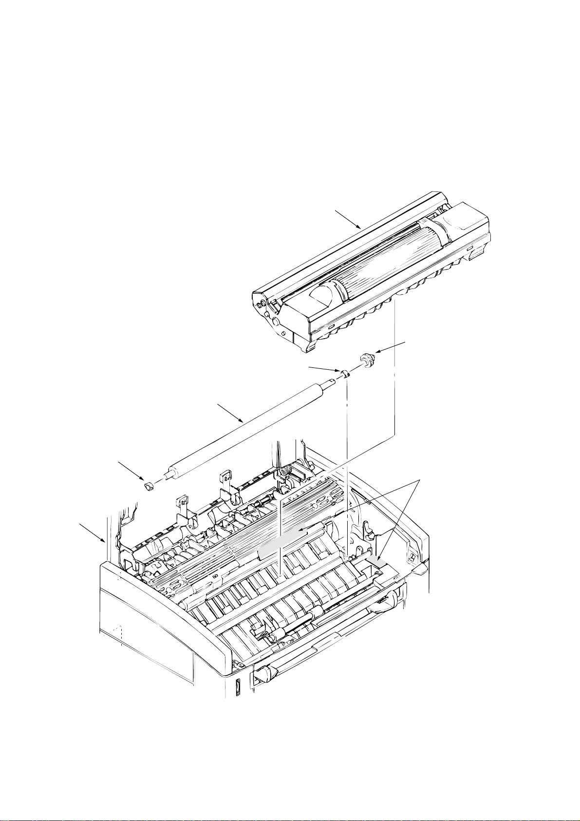
3.3.9 Heat Assy
This section explains how to dismount the heat assy and parts in the assy.
<Dismounting the heat assy>
(1) Dismount the upper cover assy. (See Section 3.3.4.)
(2) Dismount the high-voltage power supply board. (See Section 3.3.5.)
(3) Remove two screws 1, disconnect connector 2, and dismount heat assy 3.
<Dismounting parts in heat assy>
(4) Dismount heat separator D.
(5) Remove screw 4 and dismount terminal plate 6. (Handle heat assy 3 carefully because
Halogen lamp 7 comes off.)
(6) Turn left and right heat bearings 8 in the arrow direction to unlock. Then, dismount Halogen
lamp 7, heat bearing 8, heat roller 9, and heat gear C together. (Take care not to drop
Halogen lamp 7.)
(7) Dismount thermistor 0.
(8) Dismount the clamp, then thermostat A, heat contact B, and heat cord 5 together.
(9) Dismount heat contact B and heat cord 5 from thermostat A.
Caution:
Take care not to bend the claw when dismounting heat bearing 8.
3 - 14
Page 51

1
2
1
3
3 - 15
Page 52

Voltage display side
7
C
8
8
6
5
0
A
9
B
4
3 - 16
Page 53

3.3.10 Drive Shaft E (Eject) and Eject Roller
(1) Dismount the upper cover assy. (See Section 3.3.4.)
(2) Dismount top cover assy. (See Section 3.3.6.)
(3) Remove two screws 1 from heat assy (Section 3.3.9), lift the heat assy, and dismount idle
gear E (A) 2 and idle gear E (B) 3.
(4) Unlock and dismount drive shaft E (Eject) 4.
(5) Dismount two eject rollers 5.
5
4
3
2
1
1
3 - 17
Page 54

3.3.11 Pressure Roller B (Back Up Roller)
(1) Dismount the upper cover assy. (See Section 3.3.4.)
(2) Dismount the high-voltage power supply board. (See Section 3.3.5.)
(3) Dismount the heat assy. (See Section 3.3.9.)
(4) Dismount the engagement with the left ground, then pressure roller B1. (Two bearing BUs
2 and two bias springs 3 also come off at the same time.)
2
1
3
3
2
3 - 18
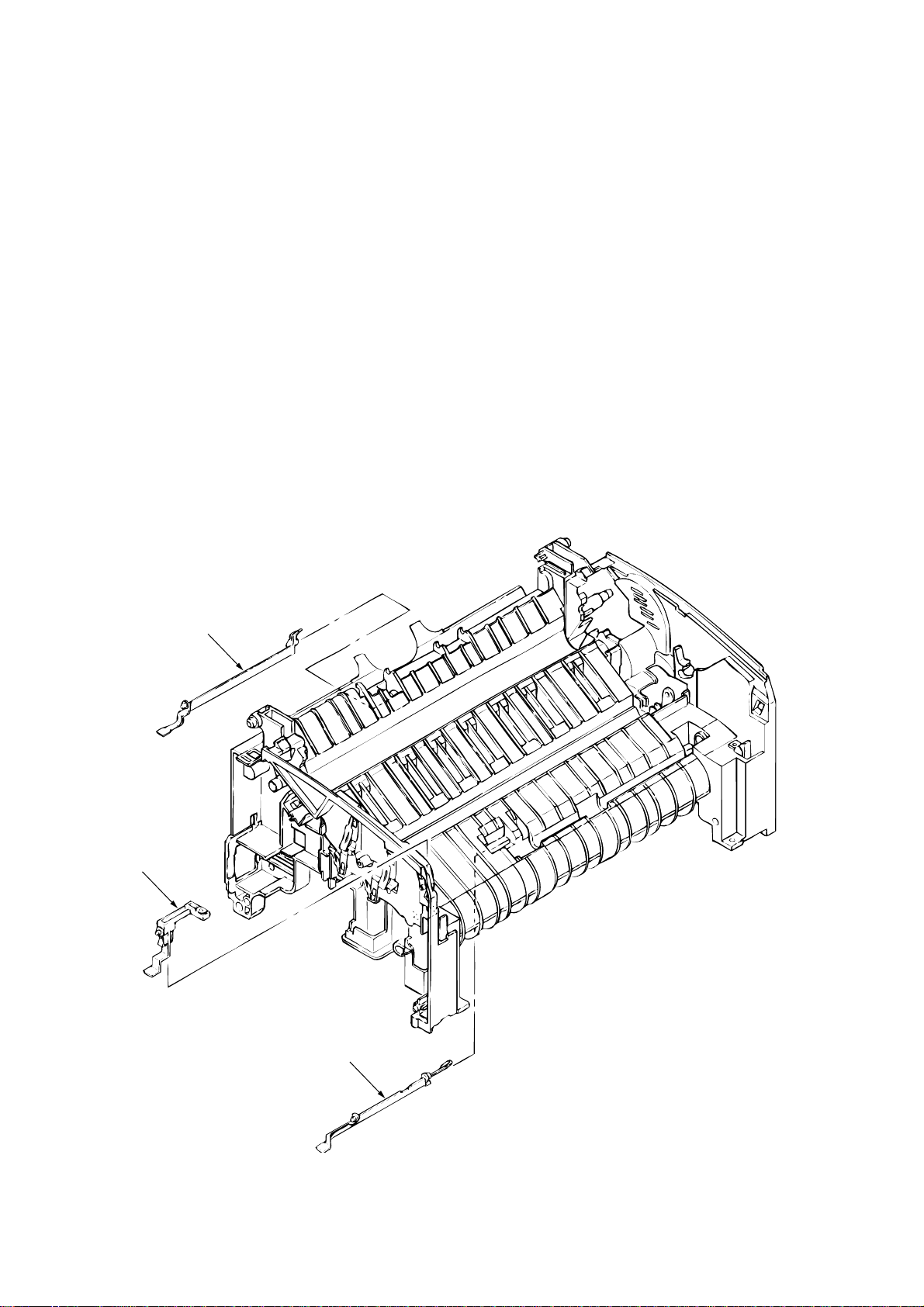
Page 55

3.3.12 Separator Guide
(1) Dismount the upper cover assy. (See Section 3.3.4.)
(2) Dismount the high-voltage power supply board. (See Section 3.3.5.)
(3) Remove four screws 1.
(4) Dismount inlet 2 from base frame 3.
<Dismounting inlet 2>
Insert a screwdriver into the hole on the side of base frame 3, remove the inlet claw from
base frame 8, and dismount inlet 2.
(5) Disconnect three cables 4 and connector A and dismount base frame 3. Then, remove
screw 0 and disconnect FG cable B.
<Disconnecting connector A>
Dismount connector A by drawing it upward while pushing the clamp lever with a standard
screwdriver.
(6) Dismount the paper holder assy. (See Section 3.3.7.)
(7) Dismount two engagements and sheet guide 5.
(8) Dismount friction pad 6, compression spring S7, and separator guide 8.
(9) Dismount paper sensor E9.
3 - 19
Page 56

3
1
7
6
8
<Dismounting Inlet>
1
Screw driver
<Disconnecting Connector>
A
2
1
5
0
B
9
4
1
4
(–) Screw driver
Clamp lever
3 - 20
Page 57

3.3.13 Pulse Motor (Main)
(1) Dismount the upper cover assy. (See Section 3.3.4.)
(2) Dismount the high-voltage power supply board. (See Section 3.3.5.)
(3) Dismount side plate M. (See Section 3.3.8.)
(4) Dismount the base frame. (See Section 3.3.12.)
(5) Remove two screws 1 and dismount pulse motor (main) 2.
2
1
3 - 21
Page 58

3.3.14 Hopping Shaft Assy
(1) Dismount the upper cover assy. (See Section 3.3.4.)
(2) Dismount the high-voltage power supply board. (See Section 3.3.5.)
(3) Dismount the base frame. (See Section 3.3.12.)
(4) Dismount the paper holder assy. (See Section 3.3.7.)
(5) Dismount the sheet guide. (See Section 3.3.12.)
(6) Dismount side plate M. (See Section 3.3.8.)
(7) Raise up roller holder 3, slide hopping shaft assy 1, and dismount roller holder 3 and
hopping roller 4. (Knock pin 5 also comes off at the same time. Take care not to lose it.)
(8) Draw out hopping shaft assy 1 to the right and dismount magnet H6.
2
4
5
1
6
3
3 - 22
Page 59

3.3.15 Resist Roller
(1) Dismount the upper cover assy. (See Section 3.3.4.)
(2) Dismount Idle gear R 3 and Gear R 4.
(3) Move resist roller 1 to the right and dismount it by lifting. (Two resist bearings 2 also come
off at the same time. Take care not to lose them.)
2
1
3
2
4
3 - 23
Page 60
3.3.16 Paper Sensor E, Paper Sensor Exit and Toner Sensor Assy
(1) Dismount the upper cover assy. (See Section 3.3.4.)
(2) Dismount the high-voltage power supply board. (See Section 3.3.5.)
(3) Dismount the base frame. (See Section 3.3.12.)
(4) Dismount the paper holder assy. (See Section 3.3.7.)
(5) Dismount the sheet guide. (See Section 3.3.12.)
(6) Dismount the heat assy. (See Section 3.3.9.)
(7) Dismount drive shaft E. (See Section 3.3.10.)
(8) Dismount paper sensor E1.
(9) Dismount paper sensor exit 2.
(10) Dismount toner sensor assy 3.
3
2
1
3 - 24
Page 61

3.3.17 Base Plate
(1) Dismount the upper cover assy. (See Section 3.3.4.)
(2) Dismount the base frame. (See Section 3.3.12.)
(3) Remove two screws 1, disconnect connector 2, and dismount power supply unit 3.
(4) Dismount insulation sheet 4.
(5) Remove two screws 5 and dismount main control board 6 from base plate 7.
3
2
5
6
1
1
4
5
7
3 - 25
Page 62

4. ADJUSTMENT
Page 63

4. ADJUSTMENT
This chapter explains adjustment necessary when a part is replaced.
This adjustment is made by changing the parameters values set in EEPROM on the main control
board. The printer driver or maintenance utility can be used to change these values.
Only servicemen and maintenance personnel can use the maintenance utility. This utility cannot
be made public for printer end users.
4.1 Adjustment Types and Functions
4.1.1 Printer Driver
(For Microsoft Windows)
This printer driver has the following functions:
• Drum counter reset
• Charge roller cleaning
Figure 4-1
(1) Drum counter reset
This function resets the life of the drum counter when the EP unit is replaced. Clicking the
“clear” button resets the life.
(2) Charge roller cleaning
This function cleans the charge roller of the EP unit; it is used when printing is unclear. For
details on how to operate this function, refer to “User’s Manual.”
4 - 1
Page 64

(For Macintosh) <only OKIPAGE4m>
(1) Drum counter reset
This function resets the life of the drum counter when the EP unit is replaced. Clicking the
“Reset” button resets the life.
(2) Charge roller cleaning
This function cleans the charge roller of the EP unit; it is used when printing is unclear. For
details on how to operate this function, refer to “User’s Manual.”
4 - 2
Page 65

4.1.2 Engine Maintenance Utility
See Appendix D.
4.2 Adjustment When Replacing a Part
The table below lists the parts that requires adjustment when they are replaced.
Part to be Replaced Adjustment
LED head
EP unit Reset the drum counter. (Refer to "User's Manual".)
Main control board Upload or download EEPROM data.
4.2.1 Setting LED Head Drive Time
Caution:
When the liminous intensity of a new LED head is the same as that of the old LED
head, do not set the LED head drive time.
Use “LED Head Making No.” in the engine menu tab of the maintenance driver to set the luminous
intensity displayed on the LED head as the LED head drive time. (See Figure 4-2.)
• Luminous intensity of LED head
Set the LED head drive time.
Set the LED head dot count.
Luminous intensity display
Figure 4-2
4 - 3
070
314
The last three digits indicate
the luminous intensity of the
LED head.
Page 66

4.2.2 Setting the LED Head Dot Count
There are two types of LED head dot count. Use the following label to identify these types. Use
“LED Head Width” in the engine menu table to set the LED head dot count. (See Figure 4-2.)
• Identifying the types of LED head dot count
Nallow Type (2496 dots)
1104G2
Full Type (2560 dots)
Figure 4-3
4 - 4
Page 67

4.2.3 Uploading and Downloading EEPROM Data
When the main control board is replaced, EEPROM data must be reflected on a new main control
board. Use “EEPROM Operations” in the option tab of the maintenance utility to reflect EEPROM
data on the new main control board. (See Figure 4-4.)
Reflect EEPROM data on the new main control board in the following procedures:
(1) Check that the printer and PC are connected by the parallel I/F, then execute the
maintenance utility.
(2) Click the "Option" button in "Main Menu Dialog".
(3) Click the “Upload” button (Upload EEPROM Data) in “EEPROM Operations.” (EEPROM
data read is completed.)
(4) The read EEPROM data is displayed in “Dialog” of the maintenance driver.
(5) Leave the display of the maintenance driver as is and replace the main control board.
(6) Click the “Download” button (Download EEPROM Data) in “EEPROM Operations”. (EEPROM
data write is completed.)
Depending on the level of a main control board failure (parallel I/O failure, etc.), however,
EEPROM data may be unable to be uploaded.
In such a case, use the maintenance utility to perform the following adjustment after replacing the
main control board:
• Setting the LED head drive time (Section 4.2.1)
• Setting the LED head dot count (Section 4.2.2)
• Setting specifications (ODA/OEL/INT-A/INT-L)
4 - 5
Page 68

5. PERIODICAL MAINTENANCE
Page 69

5. PERIODICAL MAINTENANCE
5.1 Periodical Replacement Parts
Table 5-1 lists the part and unit to be replaced periodically.
Table 5-1 Routine Replacement Parts
Part Name Replacement Time
Toner cartridge
EP unit
Caution:
Also reset the drum counter when replacing the EP unit.
When "Toner Low" is displayed.
When "Change Drum" is displayed.
5.2 Cleaning
Remove any toner or dirt and clean the circumference and inside of the printer with a waste cloth.
Caution:
5.2.1 Cleaning the LED Lens Array
When a white belt or a white stripe (void, light printing) occurs in the vertical direction of the print
surface, clean the LED lens array or replace the toner cartridge.
Caution:
Do not touch the OPC drum, LED lens array, and connector block of the LED head.
Be sure to use an LED head cleaner to clean the LED lens array.
Part to be Checked
Simultaneously
LED head Consumables
Remarks
Consumables
White belt or stripe
(void, light printing)
Figure 5-1
5 - 1
Page 70

(1) Set the LED head cleaner in the LED lens array, as shown in the figure below, and slide the
cleaner left and right several time to clean the head.
Caution:
Do not press the LED head cleaner against the LED lens array.
LED lens array
LED head cleaner
Figure 5-2
5 - 2
Page 71

6. TROUBLESHOOTING PROCEDURES
Page 72

6. TROUBLESHOOTING PROCEDURES
6.1 Troubleshooting Tips
(1) Check the basic check points written in the user’s manual.
(2) Gather detailed failure information as much as possible from the customer.
(3) Check the printer under the condition close to that under which the failure occurred.
6.2 Check Points Before Correcting Image Problems
(1) Is the printer running in proper ambient conditions?
(2) Are consumables (toner and EP unit) replaced correctly?
(3) Are sheets of paper normal?
(4) Is the EP unit set correctly?
6.3 Notes When Correcting Image Problems
(1) Do not touch the surface of the OPC drum nor place foreign matter on it.
(2) Do not expose the OPC drum to direct sunlight.
(3) Do not touch the fuser because it heats up during operation.
(4) Do not expose the image drum to light for more than five minutes at room temperature.
6.4 Preparation Before Troubleshooting
(1) Message display
The failure status of the OKIPAGE 4w plus /4m is displayed on the status monitor of the PC.
Take proper action according to the message displayed on the status monitor.
(2) LED display
The OKIPAGE 4w plus /4m is equipped with only one LED. This LED indicates one of the
following statuss:
Printer Status LED Indication
Ready Lighting
Printing in progress Blink (*1)
Recoverable alarm Blink (*2)
Unrecoverable alarm Blink (*3)
*1:
*2:
*3:
The LED blinks at a cycle of 1 second (0.5s ON)
from data reception to printing end.
The LED blinks at a cycle of 0.24 second (0.12s ON).
The LED blinks at a cycle of 0.24 second (0.12s ON).
6 - 1
Page 73

6.5 Troubleshooting
If a trouble occurs in the OKIPAGE 4w Plus/4m, troubleshoot according to the following
procedures:
Trouble
Trouble indicated by
the message displayed
on the status monitor.
Image problem (or
trouble not displayed on
the status monitor)
6.5.1 Status Monitor Message List
Table 6-1 lists the statuses and troubles to be displayed on the status monitor in the message
format.
Troubleshoot according to
"Status Monitor Message List"
(See Section 6.5.1.)
Perform detailed
troubleshooting according
to the troubleshooting flow.
(See Section 6.5.2.)
Troubleshoot according to
Section 6.5.3.
6 - 2
Page 74

Table 6-1
6 - 3
Category Status Message Display Content Remedy
Normal status 18 00
Warming Up
Online (Ready)
Power Save Mode
Toner Low
Toner Sensor
Change Drum
Manual Paper In
Printing In Progress
Ejection In Progress
Manual Request
Executive
Letter
Legal 14
Legal 13
A6
A5
A4
B5
Monarch
COM-10
DL
C5
COM-9
Status
Code
00 10
00 20
10 00
10 01
10 02
12 20
14 20
14 30
16 01
16 02
16 03
16 04
16 18
16 19
16 1A
16 21
16 50
16 51
16 5A
16 5B
16 7F
Warming-up status
Online (ready) status
Power save status
The toner amount of the toner cartridge is small.
The EP unit is not installed or the toner sensor is
faulty.
Life of EP drum
The paper is in the manual feed mode.
Printing in progress
Ejection in progress
Request the paper to be set in the manual feed
mode.
The paper sizes are as follows:
Executive, Letter, Legal 14, Legal 13, A4, A5, A6,
B5, Monarch, DL, C5, COM-10, COM-9
Normal operation
Normal operation
Normal operation
Normal operation
Replace the toner cartridge.
Install the EP unit or replace the toner sensor.
Replace the EP unit.
(
Note:
Normal operation
Normal operation
Set the requested paper in the manual feed mode.
Be sure to reset the drum counter after replacing the
EP unit.)
Page 75

Table 6-1 (Cont'd)
6 - 4
Category Status Message Display Content Remedy
Paper size error
Paper jam
Cover open
Buffer overflow
Paper Size Error
Paper Input Jam
Paper Feed Jam
Paper Exit Jam
Cover Open
Page Buffer Overflow
Print Over Run
Status
Code
30 00
31 00
32 00
33 00
4F 00
40 01
40 10
Paper of improper size was fed.
2.52" (64 mm) L 15.77" (400.56 mm)
A paper jam occurred when sheets of paper were
being supplied.
A paper jam occurred during paper feeding.
A paper jam occurred during paper ejection.
The upper cover is open.
The page buffer overflowed because there are a
large number of print data.
A print overrun occurred because print data is
complicated.
Check the paper. Also check whether more than one sheet of
paper were fed simultaneously. To release the error display,
open the cover, then close it. If this error occurs frequently, see
Section 6.5.2 3.
Check the paper. To release the error display, close the cover,
then close it. If this error occurs frequently, see Section 6.5.2
2-1.
Open the cover, then remove the jammed paper. To release
the error display, close the cover. If this error occurs frequently, see Section 6.5.2 2-2.
Open the cover, then remove the jammed paper. To release
the error display, close the cover. If this error occurs frequently, see Section 6.5.2 2-3.
To release the error display, close the cover. If this error
occurs frequently, replace the power supply board.
To release the error display, press the reset button on the
status motor of the printer driver. Install option RAM or reduce
the number of print data.
To release the error display, press the reset button on the
status motor of the printer driver. Simplify the print data format.
Device configuration error
Program ROM Check Error
Resident RAM Check Error
60 10
60 30
An error occurred during program ROM check.
An error occurred during resident RAM check.
Replace program ROM or the main control board. (When
replacing the main control board, also adjust EEPROM data.)
(See Section 4.2.4.)
Replace the main control board. (When replacing the main
control board, also adjust EEPROM data.) (See Section 4.2.4.)
Page 76

Table 6-1 (Cont'd)
Status
Category Status Message Display Content Remedy
Category Status Message Display Content Remedy
Status
Code
Code
6 - 5
Device configuration error 60 40
EEPROM Check Error
Option RAM Check Error
Fuser Error
Thermistor Error
Thermister Open Check Error
Thermister Short Check Error
Watch Dog Timeout Error
60 60
60 80
60 90
60 91
60 92
60 C0
An error occurred during EEPROM check.
An error occurred during option RAM check.
A heater timeout error occurred.
A thermistor error occurred.
The thermistor is open.
A thermistor short occurred.
A watchdog timeout occurred.
Replace the main control board. (When replacing the main
control board, also adjust EEPROM data.) (See Section
4.2.4.)
Check the connection of the Option RAM PC board. If the
option RAM PC board is faulty, replace it.
See Section 6.5.2 4.
Replace the thermistor of the heater Assy.
Replace the thermistor of the heater Assy.
Replace the thermistor of the heater Assy.
To release the error display, turn on the power supply again.
Replace the main control board.
Page 77

6.5.2 Status Message Troubleshooting
Some failures cannot be corrected according to the status message trouble list. Troubleshoot
these failures according to the following troubleshooting flowcharts:
No.
The OKIPAGE 4w Plus/4m malfunctions after the power supply has been turned on.
1.
Jam error
2.
Paper input jam
Paper feed jam
Paper exit jam
3. Paper size error
4. Fusing error
Caution:
When replacing the main control board troubleshooted according to the troubleshoot-
Item
ing flowcharts, also adjust EEPROM data. (See Section 4.2.4.)
Flowchart No.
1
2
-1
2
-2
2
-3
3
4
6 - 6
Page 78

1 The OKIPAGE 4w Plus/4m malfunctions after the power supply has been
turned on.
• Turn the power supply off, then on again.
• Is the LED lamp on?
• No Is the AC cable connected correctly?
• No Connect the AC cable correctly.
• Yes Is +5 V supplied between CN1 Pin 7 and CN1 Pin 13 of the high-voltage
power supply board?
(Pin 7: +5 V, Pin 13: 0 V)
• No Are the CN1 connectors of the high-voltage power supply board and
main control board connected correctly?
• No Connect the CN1 connectors correctly.
• Yes Is +5 V supplied between CN2 Pin 2 and CN2 Pin 3 of the main
control board?
(Pin 2: +5 V, Pin 3: 0 V)
• No Replace the power supply board.
• Yes Replace the main control board.
• Yes Is 1-2 V voltage supplied between CN1 Pin 2 and CN1 Pin 13 of the highvoltage power supply board?
• No Replace the main control board.
• Yes Replace the high-voltage power supply board.
• Yes Replace the main control board.
6 - 7
Page 79

[JAM error]
2-1 Paper input jam
• Does a paper input jam occur when the power supply is turned on?
• Yes Is the jammed paper on paper sensor E?
• Yes Remove the jammed paper.
• No Is paper sensor E (manual feed/paper) operating normally?
• No Replace paper sensor E (manual feed or paper).
• Yes Replace the high-voltage power supply board.
• No Does a paper input jam occur during paper loading?
• Yes Is the paper already fed to paper sensor E (manual feed)?
• Yes Is paper sensor E (manual feed) operating normally?
• No Replace paper sensor E (manual feed).
• Yes Check the gear block or replace high-voltage power supply board.
• No Is the paper already fed to paper sensor E (paper)?
• Yes Is paper sensor E (paper) operating normally?
• No Replace paper sensor E (paper).
• Yes Replace high-voltage power supply board.
• No Replace the stepping roller or friction pad.
• No Is the hopping roller rotating?
• Yes Check the coil resistance of magnet H. Is the resistance normal (about 120
Ω)?
• No Replace magnet H.
• Yes Is +24 V supplied between CN8 Pin 1 and CN8 Pin 2 of the main control
board?
• No Replace the main control board.
• No Check the gear block or replace the hopping shaft assy.
• No Are the CN7 connectors of the pulse motor (main) and main control board connected?
• No Connect the CN7 connectors correctly.
6 - 8
Page 80

• Yes Measure the resistance of the pulse motor (main). Is the resistance normal (about
12.6 Ω)?
• No Replace the pulse motor (main).
• Yes Replace the main control board.
6 - 9
Page 81

[JAM error]
2-2 Paper feed jam
• Does a paper feed jam occur when the power supply is turned on?
• Yes Is the jammed paper on paper sensor E (paper/exit)?
• Yes Remove the jammed paper.
• No Is paper sensor E (exit/paper) operating normally?
• No Replace paper sensor E (exit or paper).
• Yes Replace the high-voltage power supply board.
• No Has the paper arrived at paper sensor E (paper)?
• No Is the feed roller rotating?
• No Check the gear block.
• Yes Is the EP unit set correctly?
• No Set the EP unit correctly.
• Yes Check the gear block.
• Yes Has the paper arrived at the paper sensor (exit)?
• Yes Is the paper sensor (exit) operating normally?
• No Replace the paper sensor (exit).
• Yes Replace the high-voltage power supply board.
• No Check the gear block.
2-3 Paper exit jam
• Does a paper exit jam occur when the power supply is turned on?
• Yes Is the jammed paper on the paper sensor (exit)?
• Yes Remove the jammed paper.
• No Is the paper sensor (exit) operating normally?
• No Replace the paper sensor (exit).
• Yes Replace the high-voltage power supply board.
• No Check the gear block or replace the eject roller.
6 - 10
Page 82

3 Paper size error
• Is the paper of the specified size being use?
• No Use paper of the specified size.
• Yes Is paper sensor E (paper) operating normally?
• No Replace paper sensor E (paper) or clean the inlet sensor on the high-voltage
power supply board.
• Yes Is the paper sensor (exit) operating normally?
• No Replace the paper sensor (exit) or clean the outlet sensor on the high-voltage
power supply board.
• Yes Replace the high-voltage power supply board.
Exit roller
Paper sensor E (paper)
Toner
sensor
Assy
Paper sensor E (manual feed)
Paper feeding direction
Paper sensor (exit)
Heat roller
Transfer roller
Feed roller
Hopping
roller
6 - 11
Page 83

4 Heat assy error
• Turn the power supply off, then on again.
• Does the Halogen lamp of the heat assy go on?
• No Is the Halogen lamp or thermostat disconnected?
• Yes Replace the heat assy, Halogen lamp, or thermostat.
• No Replace the power supply unit.
• Yes Are the CN2 connectors of the power supply unit and main control board connected
correctly?
• No Connect the CN2 connectors correctly.
• Yes Replace the main control board.
6 - 12
Page 84

6.5.3 Image Troubleshooting
This section explains how to troubleshoot when an image problem is output as a result of the
printing.
Figure 6-3 is an example of image problem output.
Symptom
An image is light or blurred entirely. (Figure 6-3, A )
Dark background density (Figure 6-3, B )
A blank paper is output. (Figure 6-3, C )
Vertical block belt/black stripe (Figure 6-3, D )
Cyclical defect (Figure 6-3, E )
Print void
Poor fusing (An image is blurred or peeled off when it is touched.)
Vertical white belt/white stripe (Figure 6-3, F )
Flowchart No.
1
2
3
4
5
6
7
8
A Light or blurred
images entirely
D Black vertical stripes E Cyclical defect F White vertical belts
B Dark background
density
C Blank paper
or streaks
Figure 6-3 Image Problems
6 - 13
Page 85

1 An image is light or blurred entirely.
• Is the toner low? (Is "Toner Low" being displayed?)
• Yes Supply a toner.
• No Is the specified paper being used?
• No Use the specified paper.
• Yes Is the lens of the LED head dirty?
• Yes Clean the LED head.
• No Is the LED head installed correctly? (Check the CN6 connector of the main control
board.)
• No Install the LED head correctly.
• Yes Is the contact plate of the transfer roller in correct contact with the high-voltage
power supply board? (See Figure 6-4 F.)
• Yes Is the terminal of the EP unit in correct contact with the contact plate? (See Figure
6-4 A and B)?
• No Contact the terminal correctly.
• Yes Replace the transfer roller.
• Has this error been recovered?
• Yes End
• No Replace the EP unit.
• Has this error been recovered?
• Yes End
Caution:
• No Replace the main control board or high-voltage power supply board.
After replacing the EP unit, reset the drum counter. (Refer to
"Replacing the Drum Cartridge" in "User's Manual".)
6 - 14
Page 86

2 Dark background density
• Has the OPC drum being exposed to external light?
• Yes Set the OPC drum in the OKIPAGE 4w Plus/4m and wait for about 30 minutes.
• No Is the heat roller of the heat assy dirty?
• Yes Clean the heat roller.
• No Is the terminal of the EP unit in correct contact with the contact plate? (See Figure
6-4 D and Figure 6-5 D.)
• No Contact the terminal correctly.
• Yes Replace the EP unit.
• Has this error been recovered?
• Yes End
Caution:
• No Replace the main control board or high-voltage power supply board.
3 A blank paper is output.
• Is the LED head connected correctly. (Check the CN6 connector of the main control board.)
• No Connect the LED head correctly.
• Yes Is the terminal of the EP unit in correct contact with the contact plate? (See Figure
6-5 E.)
• No Contact the terminal correctly.
• Yes Replace the LED head.
• Has this error been recovered?
• Yes End
Caution:
After replacing the EP unit, reset the drum counter. (Refer to
"Replacing the Drum Cartridge" in "User's Manual".)
Set the LED head drive time when replacing the LED head. (See
Section 4.2.1.)
• No Replace the main control board or high-voltage power supply board.
6 - 15
Page 87

4 Vertical black belt/stripe
• Replace the EP unit.
• Has this error been recovered?
• Yes End
• No Replace the LED head.
• Has this error been recovered?
• Yes End
• No Replace the main control board or high-voltage power supply board.
5 Cyclic defect
EP drum
Developing roller 1.44" (36.6 mm) Replace the EP unit.
Toner supply roller 2.63" (66.8 mm) Replace the EP unit.
Charge roller 0.81" (20.6 mm) Replace the EP unit.
Caution:
Caution:
After replacing the EP unit, reset the drum counter. (Refer to
"Replacing the Drum Cartridge" in "User's Manual".)
Set the LED head drive time when replacing the LED head. (See
Section 4.2.1.)
Cycle
1.98" (50.3 mm)
Clean or replace the EP unit.
Remedy
Caution:
Cleaning roller 0.81" (20.6 mm) Replace the EP unit.
Transfer roller 1.71" (43.4 mm) Replace the EP unit.
Heat roller 2.46" (62.5 mm) Replace the heat roller.
Pressure roller B 1.98" (50.3 mm) Replace pressure roller B.
After replacing the EP unit, reset the drum counter. (Refer to "Replacing the Drum
Cartridge" in "User's Manual".)
6 - 16
Page 88

6 A blank paper is output.
• Is the contact plate of the transfer roller in correct contact with the high-voltage power supply
board?
• No Contact the contact plate of the transfer roller correctly.
• Yes Replace the transfer roller.
• Has this error been recovered?
• Yes End
• No Is the terminal of the EP unit in correct contact with the contact plate? (See Figure
6-4 A B C D E and Figure 6-5 A B C D E.)
• No Contact the terminal of the EP unit correctly.
• Yes Replace the EP unit.
• Has this error been recovered?
• Yes End
Caution:
• No Is the LED head installed correctly? (Check the CN6 connector the main control
board.)
• No Contact the LED head correctly.
• Yes Replace the LED head
• Has this error been recovered?
• Yes End
Caution:
• No Replace the main control board or high-voltage power supply board.
After replacing the EP unit, reset he drum counter. (Refer to
"Rplacing the Drum Cartridge" in "Users Manual".)
Set the LED head drive time when replacing the LED head. (See
Section 4.2.1.)
6 - 17
Page 89

7 Poor fusing
• Is the specified paper being used?
• No Use the specified paper. (xerox 4200 (20 lbs))
• Yes Is the bias spring normal? (Tension: 2.5 kg)
• No Replace the bias spring.
• Yes Are the heater connector of the heat assy and the CN1 connector of the power
supply unit connected correctly.
• No Connect the connectors correctly.
• Yes Replace the heat assy.
• Has this error been recovered?
• Yes End
• No Replace the main control board or high-voltage power supply board.
6 - 18
Page 90

8 Vertical white belt/spripe
• Is the lens of the LED head dirty?
• Yes Clean the LED head.
• No Is the contact plate of the transfer roller in correct contact with the high-voltage
power supply board? (See Figure 6-5 E.)
• No Contact the contact plate of the transfer roller correctly.
• Yes Replace the transfer roller.
• Has this error been recovered?
• Yes End
• No Is the LED head installed correctly? (Check the CN6 connector of the main control
board.)
• No Install the LED head correctly.
• Yes Replace the LED head.
• Has this error been recovered?
• Yes End
Caution:
• Yes Replace the EP unit.
• Has this error been recovered?
• Yes End
Caution:
• No Replace the main control board or high-voltage power supply board.
Set the LED head drive time when replacing the LED head. (See
Section 4.2.1.)
After replacing the EP unit, reset the drum counter. (Refer to
"Replacing the Drum Cartridge" in "User's Manual".)
6 - 19
Page 91

Contents
: Toner Supply Roller
A
: Developing Roller
B
: Charge Roller
C
: Cleaning Roller
D
: Transfer Roller
E
: Heat Roller
F
Figure 6-4
6 - 20
Page 92

Contents
: Toner Supply Roller
A
: Developing Roller
B
: Charge Roller
C
: Cleaning Roller
D
: Ground (Drum)
E
E
Figure 6-5
6 - 21
Page 93

7. WIRING DIAGRAM
Page 94

7. WIRING DIAGRAM
7.1 (a)Interconnect Signal Diagram (OKIPAGE 4w Plus)
THERM
1
2
1
123 CV0PN-N
23
22
Thermistor
5V
2
222 LED-P
321 TNRSNS-N
420 SDB2-P
OPC Drum
Charge Roller
Transfer Roller
CN2 Thermistor
High-Voltage
519 PSIN-N
618 SDBI-P
717 5V
816 WRSNS-N
915 5V
1014 DBPWM-P
Developing Roller
Power
Supply Board
CN1 Control Interface
1113 TEMP
1212 TR-VSEN
1311 0V
1410 0V
1590V
168 TRIPWM-P
1770V
186 DCLED-P
Toner Supply Roller
Roller
Cleaning
–300V
DB
+400V
CB
23
2
–1350V
CHTRHR
22
1
0V
V, –750V
1950V
204 TRZPWM-P
213 TR-ISEN
–450V
SB
222 CHPWM-P
231 PSOUT-N
CN1 (High-Voltage/Sensor Interface)
Heater
NEUTRAL
1
13
LINE
3
AC OutputCN001
Power
Red
Red25V
Blue30V
Blue40V
Green5 0VP
15V
230V/120V
L
N
FG
Switch
Supply Unit
CN003 DC Output
Purple7
Orange6 24V
8 HEATON-N
18
CN2 (Power Interface)
14
30
13
2
1
16
29
CN9 (Not Used)
17
18
36
1STB-N
2PDATA1-P
3PDATA2-P
4PDATA3-P
5PDATA4-P
6PDATA5-P
7PDATA6-P
8PDATA7-P
9PDATA8-P
10ACK-N
11BUSY-P
12PE-P
13SEL-P
14AUTOFEED-P
2
1
(HBMC-2 PCB)
4
Main Control Board
1
CN7 (Main Motor) CN8 (Power Clutch)
CN4 (Parallel Interface)
1
19
15NC
16SG
17SG
185V
19SG
20SG
21SG
22SG
23SG
24SG
25SG
26SG
27SG
28SG
29SG
30SG
31IPRIME-N
32FAULT-N
33SG
34NC
35HILEVEL
36SELIN-N
14
10VP
13
20VP
35V
45V
50V
6HDDT0-P
7HDDT1-P
8HDCLK-P
9HDLD-P
10STB1-N
CN6 (LED Head)
2
11STB2-N
12STB3-N
13STB4-N
14FG
12P JON
4DMPH4-P
3DMPH3-P
2DMPH2-P
1DMPH1-P
1
0VP
Ω
Orange
12.6
Yellow
M
Ω
120
Brown
Black
LED Head
7 - 1
Page 95

7.1 (b)Interconnect Signal Diagram (OKIPAGE 4m)
THERM
1
2
1
123 CV0PN-N
23
22
5V
2
222 LED-P
321 TNRSNS-N
420 SDB2-P
Thermistor
OPC Drum
Charge Roller
Transfer Roller
CN2 Thermistor
High-Voltage
519 PSIN-N
618 SDBI-P
717 5V
816 WRSNS-N
915 5V
1014 DBPWM-P
Developing Roller
Power
Supply Board
1113 TEMP
1212 TR-VSEN
1311 0V
1410 0V
1590V
168 TRIPWM-P
1770V
186 DCLED-P
Toner Supply Roller
Roller
Cleaning
–300V
DB
+400V
CB
–1350V
V, –750V
CHTRHR
0V
–450V
SB
CN1 Control Interface
23
22
1950V
204 TRZPWM-P
213 TR-ISEN
222 CHPWM-P
231 PSOUT-N
1
2
CN1 (High-Voltage/Sensor Interface)
Heater
NEUTRAL
1
13
LINE
3
AC OutputCN001
Power
Red
Red25V
Blue30V
Blue40V
15V
230V/120V
L
N
FG
Switch
Supply Unit
CN003 DC Output
Green5 0VP
Purple7
Orange6 24V
8 HEATON-N
18
CN2 (Power Interface)
14
30
13
2
1
16
29
CN9 (Not Used)
17
18
36
1STB-N
2PDATA1-P
3PDATA2-P
4PDATA3-P
5PDATA4-P
6PDATA5-P
7PDATA6-P
8PDATA7-P
9PDATA8-P
10ACK-N
11BUSY-P
12PE-P
13SEL-P
14AUTOFEED-P
8RXD
6
3
7NC
6TXD
12
4
5RXD
4SG
78
3TXD
2NC
5
CN5 Mac interface
(HBMC-2 PCB)
Main Control Board
CN4 (Parallel Interface)
1
19
15NC
16SG
17SG
185V
19SG
20SG
21SG
22SG
23SG
24SG
25SG
26SG
27SG
28SG
29SG
30SG
31IPRIME-N
32FAULT-N
33SG
34NC
35HILEVEL
36SELIN-N
13
14
10VP
20VP
35V
45V
50V
6HDDT0-P
7HDDT1-P
8HDCLK-P
CN6 (LED Head)
9HDLD-P
10STB1-N
11STB2-N
12STB3-N
1XCLK-N
2
1
12P JON
4
4DMPH4-P
3DMPH3-P
2DMPH2-P
1DMPH1-P
1
CN7 (Main Motor) CN8 (Power Clutch)
1
2
13STB4-N
14FG
0VP
Ω
Orange
12.6
Yellow
M
Ω
120
Brown
Black
LED Head
7 - 2
Page 96

7.2 PCB Layout
7.2.1 Main Control Board (HBMC-2 PCB) (OKIPAGE 4w Plus)
Short Plug
SP1
S W I
1 2
Plug Setting
Content
A External EPROM is valid.
Mask ROM in the CPU is valid.B
Remarks
For a Chinese product and all maintenance parts.
For all products except Chinese product.
7 - 3
Page 97

7.2 PCB Layout
7.2.2 Main Control Board (HBMC-3 PCB) (OKIPAGE 4m)
Short Plag
SP1
DIP Switch
SW1-1
SW1-2
S W I
1 2
Plag Setting
Content
A External EPROM is valid.
Mask ROM in the CPU is valid.B
Switch Setting
UPPER SIDE*
LOWER SIDE
UPPER SIDE*
LOWER SIDE
AUTO I/F
FIX I/F (By SW2-2)
FIX PARALLEL I/F
FIX MAC I/F
Content
*Default setting. Do not change.
Remarks
not used
7 - 4
Page 98

7.2.3 High-Voltage Power Supply Board
7 - 5
Page 99

8. PARTS LIST
Page 100

8. PARTS LIST
6
5
4
3
*1
1
Figure 8-1 Cover Assy Upper
2
8 - 1
 Loading...