

Page 1

Optical Transmittance Spectrophotometer
(OTS)
Installation and Operation Manual
Document Number OTS-00000-000-02-1008
Office: Ocean Optics, Inc. World Headquarters
830 Douglas Ave., Dunedin, FL, USA 34698
Phone 727.733.2447
Fax 727.733.3962
8 a.m.– 8 p.m. (Mon-Thu), 8 a.m.– 6 p.m. (Fri) EST
E-mail: Info@OceanOptics.com (General sales inquiries)
Orders@OceanOptics.com (Questions about orders)
TechSupport@OceanOptics.com (Technical support)
Page 2

Additional
Offices:
Ocean Optics Asia
666 Gubei Road, Kirin Tower, Suite 601B, Changning District, Shanghai,
200336 PRC
Phone 86.21.6295.6600
Fax 86.21.6295.6708
E-Mail Sun.Ling@OceanOptics.com
Ocean Optics Europe
Regional Headquarters:
Maybachstrasse 11, 73760 Ostfildern, Germany
Phone 49-(0)711-34-16-96-0
Fax 49-(0)711-34-16-96-85
E-Mail Info@OceanOptics.eu
Sales & Support:
Geograaf 24, 6921 EW DUIVEN, The Netherlands
Phone 31-(0)26-3190500
Fax 31-(0)26-3190505
E -Mail Info@OceanOptics.eu
Copyright © 2001-2008 Ocean Optics, Inc.
All rights reserved. No part of this publication may be reproduced, stored in a retrieval system, or transmitted, by any means, electronic,
mechanical, photocopying, recording, or otherwise, without written permission from Ocean Optics, Inc.
This manual is sold as part of an order and subject to the condition that it shall not, by way of trade or otherwise, be lent, re-sold, hired out or
otherwise circulated without the prior consent of Ocean Optics, Inc. in any form of binding or cover other than that in which it is published.
Trademarks
All products and services herein are the trademarks, service marks, registered trademarks or registered service marks of their respective owners.
Limit of Liability
Every effort has been made to make this manual as complete and as accurate as possible, but no warranty or fitness is implied. The information
provided is on an “as is” basis. Ocean Optics, Inc. shall have neither liability nor responsibility to any person or entity with respect to any loss or
damages arising from the information contained in this manual.
Page 3

Table of Contents
About This Manual .......................................................................................................... iii
Document Purpose and Intended Audience.............................................................................. iii
Document Summary..................................................................................................................iii
Product-Related Documentation ............................................................................................... iii
Upgrades......................................................................................................................... iii
Warranty.......................................................................................................................... iv
Service ............................................................................................................................ iv
Chapter 1: Introduction ......................................................................1
Product Overview ............................................................................................................ 1
Features .......................................................................................................................... 2
Characteristics ...................................................................................................................... 2
Performance.......................................................................................................................... 3
Computer & Power Requirements ........................................................................................ 3
EEPROM Utilization .................................................................................................................. 3
Shipment Components.................................................................................................... 3
Chapter 2: Installing the OTS............................................................. 5
Overview ......................................................................................................................... 5
OTS Installation............................................................................................................... 5
Measuring Transmittance................................................................................................ 6
Chapter 3: Troubleshooting...............................................................11
Overview ......................................................................................................................... 11
OTS Connected to Computer Prior to Software Installation ............................................ 11
Windows Operating Systems ....................................................................................................11
Remove the Unknown Device from Windows Device Manager ........................................... 11
Remove Improperly Installed Files........................................................................................ 12
OTS-00000-000-02-1008 i
Page 4

Table of Contents
Appendix A: Bulb Replacement.........................................................13
Overview ......................................................................................................................... 13
Replacing the Bulb .......................................................................................................... 13
Index .....................................................................................................17
ii OTS-00000-000-02-1008
Page 5
About This Manual
Document Purpose and Intended Audience
This document provides the user of the Optical Transmittance Spectrophotometer (OTS) with instructions
for setting up, operating, and replacing the bulb.
Document Summary
Chapter Description
Chapter 1: Introduction
Chapter 2: Installing the OTS
Chapter 3: Troubleshooting
Appendix A: Bulb Replacement
Contains descriptive information about the OTS system. It also
provides a list of system requirements, interface options, and
shipment components.
Provides installation instructions.
Contains recommended steps to isolate and correct common
problems.
Provides instructions for replacing the bulb in the internal HL2000HP-FSHA.
Product-Related Documentation
You can access documentation for Ocean Optics products by visiting our website at
http://www.oceanoptics.com. Select Technical → Operating Instructions, then choose the appropriate
document from the available drop-down lists. Or, use the Search by Model Number field at the bottom
of the web page.
Engineering-level documentation is located on our website at Technical → Engineering Docs.
You can also access operating instructions for Ocean Optics products from the Software and Technical
Resources CD that ships with the product.
Upgrades
Occasionally, you may find that you need Ocean Optics to make a change or an upgrade to your system.
To facilitate these changes, you must first contact Customer Support and obtain a Return Merchandise
Authorization (RMA) number. Please contact Ocean Optics for specific instructions when returning a
product.
OTS-00000-000-02-1008 iii
Page 6

About This Manual
Warranty
Our 3-Year Warranty, currently the best in the industry, covers the Ocean Optics miniature fiber optic
spectrometer inside the OTS – regardless of the application – from manufacturing defects. It ensures you
of the highest level of craftsmanship and reliability for years to come.
The OTS light source is covered for one year (not including the bulb).
Our warranty information is located at
http://www.oceanoptics.com/corporate/3-
year%20warranty%20certificate.pdf.
Service
For additional peace of mind, we offer an Annual Service Package (ASP) to maintain your scientific
investment. This plan includes yearly wavelength calibration, preventive maintenance service and
privileged customer status plan. More information on available ASPs is located at
http://www.oceanoptics.com/Services/servicepackages.asp
Contact us to learn more about these great service packages.
iv OTS-00000-000-02-1008
Page 7
Chapter 1
Introduction
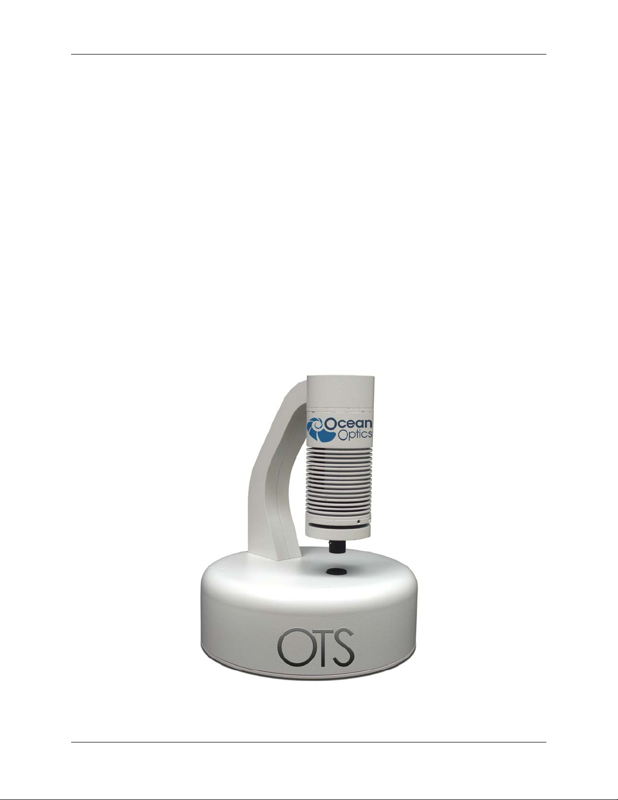
Product Overview
The Ocean Optics Optical Transmittance Spectrophotometer (OTS) is a compact system consisting of a
USB2000+ Spectrometer, an HL2000-HP-FHSA light source and a FOIS integrating sphere that is
specifically designed for accurate, repeatable measurements of optical filters, glass and ophthalmic lenses.
OTS is ideal for both in-line and in-lab applications where transmittance accuracy (to +/- 1.0%) and
precision (+/- 0.1%) are critical. Common applications include measurement of optical coatings, windows
and filters, and glass and plastic components. The OTS is particularly useful for measuring tint color,
photopic transmittance and UV cutoff of ophthalmic lenses and for characterizing photochromic,
eletrochromic and sun lens materials.
Ocean Optics Optical Transmittance Spectrophotometer
OTS-00000-000-02-1008 1
Page 8
1: Introduction
About the System
The OTS covers the 380-780 nm wavelength range and accepts samples from 10-150 mm in diameter and
up to 10 mm thickness. The system consists of the following components:
• High-resolution miniature linear CCD-
array USB2000 Spectrometer configured
for 380-780 nm (SLIT-50, Grating #1)
• High-power, tungsten halogen light
source
• Fiber optic integrating sphere for
collecting signal transmitted through the
sample
• Optics for improved beam collimation
and spectral sensitivity distribution
(including a BG34 Schott standard
colored glass filter for greater sensitivity
and less noise in the total visible
spectrum)
• Short optical fiber to channel signal from the integrating sphere to the spectrometer
• Customized lens transmittance and color calculation software measures and displays up to 10
measurements at once. This custom software calculates T(avg 380-780nm), Luminous
Transmittance Tv, and color: L* a* b*, hue (h) and Chroma (C*).
Features
Characteristics
Spectral range: 380-780 nm
Detection: Miniature fiber optic spectrometer
Light source: High-power tungsten halogen (360-2000 nm)
Sample collection: Fiber optic integrating sphere
Color calculations: CIE color characteristics
Measurement calibration: Manual calibration using known filter standard (not included);
calibration time <30 seconds
System calibration: Recommend annual recalibration
Transmittance calibration
standards:
Typical samples measured: Windows, filters, glass and plastic lenses
Available (contact an
Applications Scientist for details)
Sample size: 10-150 mm diameter, up to 10 mm thickness
Optical stage: White powder-coated aluminum (optional black anodized aluminum
version available)
2 OTS-00000-000-02-1008
Page 9

1: Introduction
Software: Customized lens transmittance and color calculation software
Quality: Conforms with ISO 8980-3, ISO 13666:1998, and CIE standards and
norms
Manufacturing compliance: CE/UL/RoHS/WEEE
Performance
Transmittance measurement
accuracy:
Transmittance measurement
precision:
Data acquisition time: typically <5 seconds
Light source output: 20 watts
Light source stability: 0.5% (~15 minutes to stabilize)
Light source drift: <0.3% per hour
Bulb lifetime: 2,000 hours
Bulb color temperature: 3,000 K
Light source temperature: 5 °C - 35 °C
Light source humidity: 5-95% RH
+/-1.0%
+/-0.1%
Computer & Power Requirements
Operating systems: Windows Operating System
Computer interfaces: USB 2.0 @ 480 Mbps
Power requirements: 100-240V, 50-60 Hz, 1.5A
EEPROM Utilization
An EEPROM memory chip in each spectrometer contains wavelength calibration coefficients, linearity
coefficients, and a serial number unique to each individual spectrometer. The OOI software application
reads these values directly from the spectrometer, enabling the ability to “hot-swap” spectrometers
between computers without entering the spectrometer coefficients manually on each computer.
Shipment Components
OTS system
OTS-00000-000-02-1008 3
Page 10

1: Introduction
The following information and documentation also ships with the OTS:
Packing List
The packing list is inside a plastic bag attached to the outside of the shipment box (the invoice
arrives separately). It lists all items in the order, including customized components in the
spectrometer (such as the grating, detector collection lens, and slit). The packing list also includes
the shipping and billing addresses, as well as any items on back order.
Wavelength Calibration Data Sheet
Each spectrometer is shipped with a Wavelength Calibration Data Sheet that contains information
unique to your spectrometer. Your spectrometer operating software reads this calibration data
from your spectrometer when it interfaces to a computer via the USB port.
Note
Please save the Wavelength Calibration Data Sheet for future reference.
Software and Technical Resources CD
Each order ships with the Ocean Optics Software and Resources CD. This disc contains software,
operating instructions, and product information for all Ocean Optics software, spectrometers, and
spectroscopic accessories. You need Adobe Acrobat Reader version 6.0 or higher to view these
files. Ocean Optics includes the Adobe Acrobat Reader on the Software and Technical Resources
CD.
All Ocean Optics software requires a password during the installation process. You can locate
passwords for the other purchased software applications on the back of the Software and
Technical Resources CD package.
4 OTS-00000-000-02-1008
Page 11

Chapter 2
Installing the OTS
Overview
You must install the operating software application prior to connecting your OTS system to a computer.
The Ocean Optics software installs the drivers required for the OTS spectrometer installation. If you do
not install the software first, the system will not properly recognize the OTS.
If you have already connected your OTS system to the computer prior to installing the operating software,
consult Chapter 3: Troubleshooting for information on correcting a corrupt OTS installation.
OTS Installation
This section contains instructions for connecting the OTS to a computer. To connect the OTS to a
computer via the USB port, the computer must be running a Windows 2000/XP/Vista operating system.
►
Procedure
Follow the steps below to connect the OTS to a computer via the USB port:
1. Install the spectrometer operating software on the destination computer.
2. Locate the USB cable (USB-CBL-1) provided with the OTS.
3. Insert the square end of the cable into the USB port on the OTS.
4. Insert the rectangular end of the cable into the USB port of the computer.
5. Plug the power cord for the OTS light source into a power outlet (100-240V, 50-60Hz).
If you installed the software prior to connecting the spectrometer, the software installs the spectrometer
drivers. If the drivers do not successfully install (or if you connected the spectrometer to the computer
before installing the software), consult Chapter 3:
Once you install the software and hardware, you are ready to take measurements.
Troubleshooting.
OTS-00000-000-02-1008 5
Page 12

2: Installing the OTS
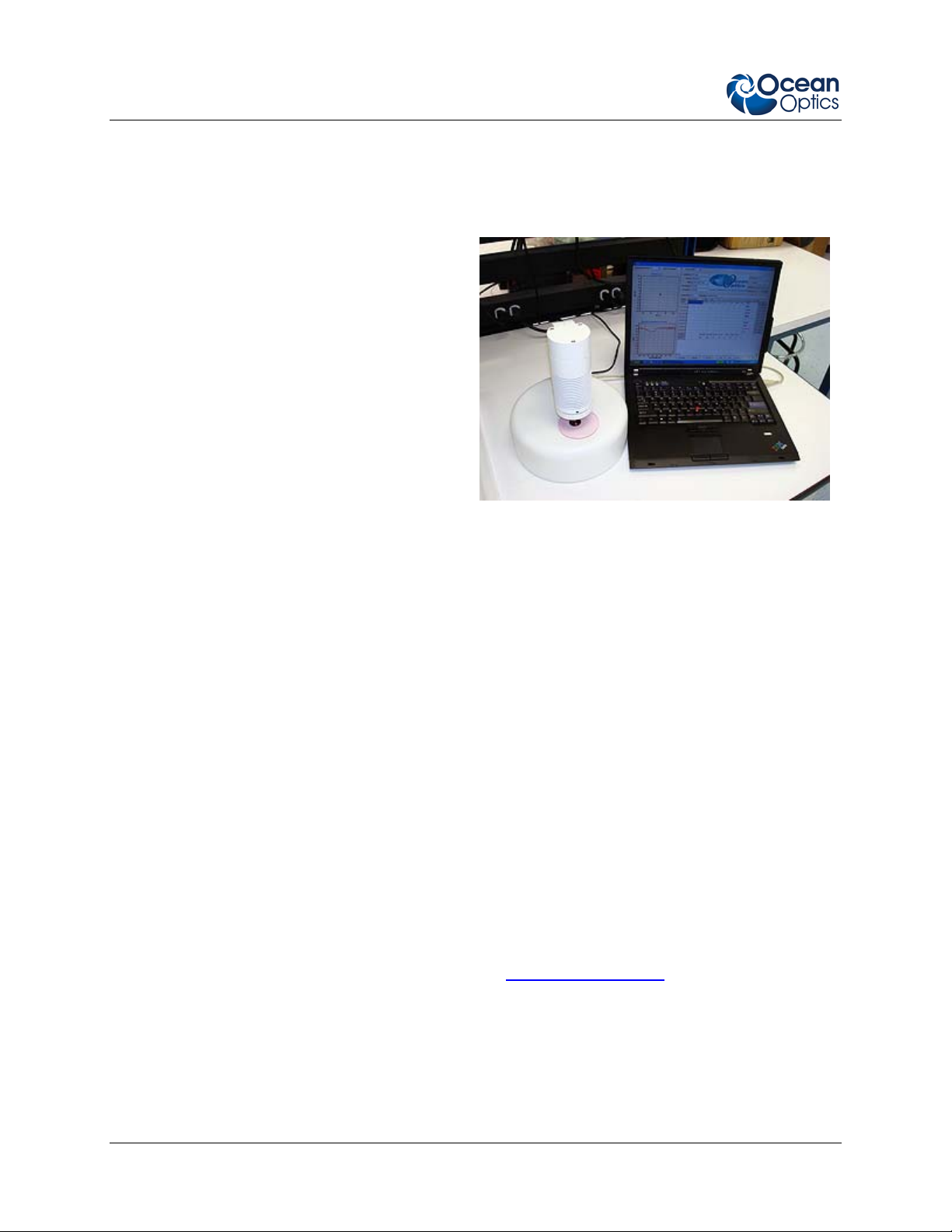
Measuring Transmittance
To use the OTS to measure transmittance of lenses, windows, etc., be sure that light source cord is
connected with appropriate power (100-240V, 50-60Hz) to the rear of the OTS, and also the USB cord is
connected between the OTS and a computer on which the OTS software has been loaded.
►
Calibration Procedure
1. Turn on the OTS by flipping the lighted rocker switch on the side of the lamp support arm to the
“On” position. If the light in the switch does not come on, check the power cord connections.
2. Double-click the OTS.exe application icon to open the OTS software. The OTS main screen
appears.
OTS Main Screen (just after opening software)
3. Set up spectrometer parameters by clicking the button.
4. In the Scan Parameters window, click the
where the signal peak is between 3400 and 3600 counts, and with no signal saturation anywhere
in the spectrum. Then set scan average, and boxcar. (For example, integration time = 9, scans
averaged = 50, and Boxcar = 2). Close the window to return to the main screen.
Examples of correctly and incorrectly adjusted intensity profiles are shown below:
6 OTS-00000-000-02-1008
button and adjust integration time to a value
Page 13

2: Installing the OTS
Correctly Adjusted Integration Time
Incorrectly Adjusted Integration Time: Integration time set too high; part of spectrum is saturated
OTS-00000-000-02-1008 7
Page 14

2: Installing the OTS
Incorrectly Adjusted Integration Time: Integration time set too low
5. When finished with setting parameters, close the Scan Parameters window by clicking the red
in the upper right corner of the Scan Parameters window (not the OTS window!).
6. Calibrate OTS. To do this, click the drop-down menu in the Reference box (in the upper right of
the Main screen) to choose to calibrate to either Fused SiO2 or Air. Then, click the
button. The following popup dialog box appears:
7. If you are calibrating using fused SiO2 as the standard, place the thin SiO2 sample on the stage.
If you are calibrating using air as the standard, place no sample on the stage.
Click OK, and leave the calibration piece in place until the following dialog box appears:
8. Click OK to return to the Main screen.
8 OTS-00000-000-02-1008
Page 15

2: Installing the OTS
► Measurement of Transmittance Procedure
1. Place a tint sample on the stage and click a button to acquire the spectra and calculate the
color info for the sample. Up to 10 measurements may be made and compared. Average
Transmittance T(λ), Luminous Transmittance τ
, and the color parameters L*a*b*, along with
v
hue and Chroma are displayed for each measurement.
Luminous transmittance is calculated in accordance with ISO 13666:1998(E/F). L*, a*, b*, hue,
and Chroma are all calculated from the measured spectra using the D65 illuminant and 10-degree
observer.
The average and standard deviation for all data displayed are shown at the bottom of the table.
The color of the symbols in the a*-b* plot, as well as the data in the spectral transmittance plot
are shown in the column labeled
2. You can add details to specify laboratory, analyst, part number, lot number, etc.
3. Adjust the scaling on the charts, if desired. To do this, right-click on either chart, and then adjust
to the desired axis range for the vertical and horizontal axes of both the a*-b* and spectral
transmittance plots.
4. Delete individual data sets by clicking the Clear button pertaining to that row of data. Clear all
displayed data at once by clicking the Clear All button.
OTS-00000-000-02-1008 9
.
Page 16

2: Installing the OTS
► Creating Reports Procedure
By clicking the button, the information on the screen, including charts, data table, and
sampling details may be previewed, printed out, or saved in Native Printer Output (PRN) or Rave
Snapshot File (NDR) format.
► Saving Data Procedure
Data can be saved in .txt format, for later retrieval by the OTS software or for viewing or further
management using spreadsheet software. Press the
button and assign a name and
location for the new .txt file. Load these .txt files in the OTS software for later reviewing of the
saved results by pressing the
button.
10 OTS-00000-000-02-1008
Page 17

Chapter 3
Troubleshooting
Overview
The following sections contain information on troubleshooting issues you may encounter when using the
OTS system.
OTS Connected to Computer Prior to Software Installation
Windows Operating Systems
If you connected your Ocean Optics OTS device to the computer prior to installing your spectrometer
operating software application on a Windows platform, you may encounter installation issues that you
must correct before your Ocean Optics device will operate properly.
Follow the applicable steps below to remove the incorrectly installed device, device driver, and
installation files.
Note
If these procedures do not correct your device driver problem, you must obtain the
Correcting Device Driver Issues document from the Ocean Optics website:
http://www.oceanoptics.com/technical/engineering/correctingdevicedriverissues.pdf.
Remove the Unknown Device from Windows Device Manager
► Procedure
1. Open Windows Device Manager. Consult the Windows operating instructions for your computer
for directions, if needed.
2. Locate the Other Devices option and expand the Other Devices selection by clicking on the "+"
sign to the immediate left.
OTS-00000-000-02-1008 11
Page 18

3: Troubleshooting
Note
Improperly installed USB devices can also appear under the Universal Serial Bus
Controller option. Be sure to check this location if you cannot locate the unknown device.
3. Locate the unknown device (marked with a large question mark). Right-click on the Unknown
Device listing and select the Uninstall or Remove option.
4. Click the OK button to continue. A warning box appears confirming the removal of the Unknown
Device. Click the OK button to confirm the device removal.
5. Disconnect the OTS from your computer.
6. Locate the section in this chapter that is appropriate to your operating system and perform the
steps in the following
Remove Improperly Installed Files section.
Remove Improperly Installed Files
► Procedure
1. Open Windows Explorer.
2. Navigate to the Windows | INF directory.
Note
If the INF directory is not visible, you must disable the Hide System Files and Folders
and Hide File Extensions for Known File Types options in Windows Folder Options.
Access Windows Folder Options from Windows Explorer, under the Tools | Folder
Options menu selection.
3. Delete the OOI_USB.INF in the INF directory. If your computer is running either the Windows
2000 or XP operating system, you must also delete the OOI_USB.PNF file in the INF directory.
4. Navigate to the Windows | System32 | Drivers directory.
5. Delete the EZUSB.SYS file.
6. Reinstall your Ocean Optics application and reboot the system when prompted.
7. Plug in the USB device.
The system is now able to locate and install the correct drivers for the USB device.
12 OTS-00000-000-02-1008
Page 19

Appendix A
Bulb Replacement
Overview
The OTS system contains the HL2000-HP-FSHA light source, which consists of a halogen bulb (Part No.
HL-2000-HP-B), attenuator and TTL shutter. Specifications for this light source are as follows:
Wavelength range 360 nm – 1700 nm
Stability 0.5 %
Drift <0.1% per hour
Time to stabilize Approximately 5 Minutes
Output to bulb 2V DC / 1,67A
Bulb life time 2000 h
Characteristic Focused
Shutter TTL max. 5Hz
DB-15 Connector PIN 13: TTL PIN 10: Ground
Bulb color temperature 3.000K
Room temperature 5°C – 35°C
Humidity 5 - 95% at 40°C
Output 20W
Before replacing the bulb in the HL2000-HP-FHSA, disconnect the lamp from your
power source and allow the unit to cool for at least twenty minutes, if necessary.
HL-2000-FHSA-HP
WARNING
Replacing the Bulb
► Procedure
Refer to the following figure and perform the steps below to replace the bulb in the HL-2000-
FHSA Light Source:
OTS-00000-000-02-1008 13
Page 20

B: Specifications
Connection
Block
Rear / Electronics Board
Lamp
Housing
Fan Wires
HL-2000-FHSA Bulb Replacement Diagram
1. Unplug the power connector from the power socket on the back of the OTS unit.
2. While holding the light source, carefully remove the screws on the rear of the unit with the
provided 2.5mm Allen wrench.
3. After removing the screws, lower the light source slightly until the connection wires are visible.
4. Carefully disconnect the 15-pin D-sub connector as well as the power connection from the top
plate of the light source.
14 OTS-00000-000-02-1008
Page 21

B: Specifications
5. Remove the rear of the light source and remove the electronics mounting plate from the unit,
taking particular care not to disconnect the fan wires.
6. Locate the set screw inside a small hole between fan blades. Loosen the set screw slightly with
the provided 1.3mm Allen key, until the bulb is loose and can be pulled out (set screw need not
be removed from light source body).
7. Remove the bulb from the light source.
8. Disconnect the wires from the connection block.
OTS-00000-000-02-1008 15
Page 22

B: Specifications
9. Replace the bulb and reconnect the wires to the connection block.
10. Slide the lamp into the housing and secure the housing with the bottom screw.
11. Slide the electronics board back into the light source, taking particular care to ensure that the
wires do not come into contact with the fan blades.
12. Reconnect the power connection and 15-pin D-Sub connector, taking care not to change the
setting on the toggle switches on top of the unit. (The Power switch should be set to “ON” and
the Shutter switch should be set to “TTL”).
13. Secure the light source to the OTS using the 3 hex screws at the top of the instrument.
16 OTS-00000-000-02-1008
Page 23

Index
A
Adobe Acrobat Reader, 4
B
bulb
part number, 13
replacement, 13
bulb replacement
diagram, 14
C
calibration, 6
D
diagrams
bulb replacement, 14
document
audience, iii
purpose, iii
summary, iii
E
L
light source
bulb replacement, 13
specifications, 13
M
measuring transmittance, 9
memory chip, 3
O
overview, 1
P
packing list, 4
passwords, 4
product-related documentation, iii
R
reports
creating, 10
EEPROM, 3
features, 2
F
saving data, 10
service, iv
setup, 5
shipment components, 3
Software and Resources Library CD, 4
S
I
T
Installation, 5
integration time
adjusting, 6
OTS-00000-000-02-1008 17
transmittance
measuring, 9
Troubleshooting, 11
Page 24

Index
upgrades, iii
U
W
warranty, iv
Wavelength Calibration Data File, 4
Wavelength Calibration Data Sheet, 4
18 OTS-00000-000-02-1008
 Loading...