

NordicTrack NTL290121 Owner's Manual
www.nordictrackfi tness.com
Model No. NTL29012.1
Serial No.
Write the serial number in the space
above for reference.
Serial Number
Decal
ACTIVATE YOUR
WARRANTY
To register your product and
activate your warranty today, go
to www.nordictrackservice.com/
registration.
USER’S MANUAL
CUSTOMER CARE
For service at any time, go to
www.nordictrackservice.com.
Or call 1-800-TO-BE-FIT
(1-800-862-3348)
Mon.–Fri. 6 a.m.–6 p.m. MT
Sat. 8 a.m.–4 p.m. MT
Please do not contact the store.
CAUTION
Read all precautions and instructions in this manual before using
this equipment. Save this manual
for future reference.
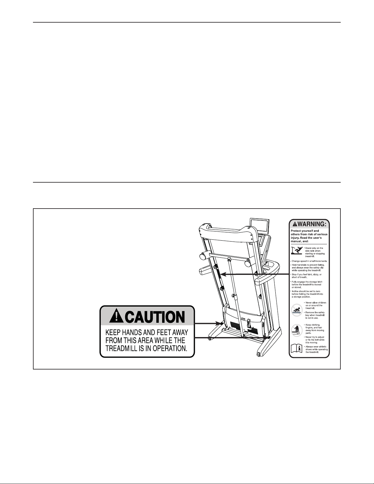
TABLE OF CONTENTS
WARNING DECAL PLACEMENT . . . . . . . . . . . . . . . . . . . . . . . . . . . . . . . . . . . . . . . . . . . . . . . . . . . . . . . . . . . . . . .2
IMPORTANT PRECAUTIONS . . . . . . . . . . . . . . . . . . . . . . . . . . . . . . . . . . . . . . . . . . . . . . . . . . . . . . . . . . . . . . . . . .3
BEFORE YOU BEGIN. . . . . . . . . . . . . . . . . . . . . . . . . . . . . . . . . . . . . . . . . . . . . . . . . . . . . . . . . . . . . . . . . . . . . . . . 8
PART IDENTIFICATION CHART. . . . . . . . . . . . . . . . . . . . . . . . . . . . . . . . . . . . . . . . . . . . . . . . . . . . . . . . . . . . . . . . 9
ASSEMBLY . . . . . . . . . . . . . . . . . . . . . . . . . . . . . . . . . . . . . . . . . . . . . . . . . . . . . . . . . . . . . . . . . . . . . . . . . . . . . . .10
THE CHEST HEART RATE MONITOR. . . . . . . . . . . . . . . . . . . . . . . . . . . . . . . . . . . . . . . . . . . . . . . . . . . . . . . . . . 18
OPERATION AND ADJUSTMENT . . . . . . . . . . . . . . . . . . . . . . . . . . . . . . . . . . . . . . . . . . . . . . . . . . . . . . . . . . . . .21
HOW TO FOLD AND MOVE THE TREADMILL . . . . . . . . . . . . . . . . . . . . . . . . . . . . . . . . . . . . . . . . . . . . . . . . . . .38
TROUBLESHOOTING . . . . . . . . . . . . . . . . . . . . . . . . . . . . . . . . . . . . . . . . . . . . . . . . . . . . . . . . . . . . . . . . . . . . . . 39
EXERCISE GUIDELINES . . . . . . . . . . . . . . . . . . . . . . . . . . . . . . . . . . . . . . . . . . . . . . . . . . . . . . . . . . . . . . . . . . . .41
PART LIST. . . . . . . . . . . . . . . . . . . . . . . . . . . . . . . . . . . . . . . . . . . . . . . . . . . . . . . . . . . . . . . . . . . . . . . . . . . . . . . . 42
EXPLODED DRAWING. . . . . . . . . . . . . . . . . . . . . . . . . . . . . . . . . . . . . . . . . . . . . . . . . . . . . . . . . . . . . . . . . . . . . .44
ORDERING REPLACEMENT PARTS. . . . . . . . . . . . . . . . . . . . . . . . . . . . . . . . . . . . . . . . . . . . . . . . . . . Back Cover
LIMITED WARRANTY. . . . . . . . . . . . . . . . . . . . . . . . . . . . . . . . . . . . . . . . . . . . . . . . . . . . . . . . . . . . . . . Back Cover
WARNING DECAL PLACEMENT
This drawing shows the locations of the warning
decals. If a decal is missing or illegible, call the
telephone number on the front cover of this
manual and request a free replacement decal.
Apply the decal in the location shown. Note:
The decals may not be shown at actual size.
NORDICTRACK is a registered trademark of ICON IP, Inc.
2

IMPORTANT PRECAUTIONS
WARNING: To reduce the risk of burns, fire, electric shock, or injury to persons, read
all important precautions and instructions in this manual and all warnings on your treadmill before
using your treadmill. ICON assumes no responsibility for personal injury or property damage sustained by or through the use of this product.
1. It is the responsibility of the owner to ensure
that all users of this treadmill are adequately
informed of all warnings and precautions.
2. Before beginning any exercise program,
consult your physician. This is especially
important for persons over age 35 or persons
with pre-existing health problems.
3. Use the treadmill only as described in this
manual.
4. The treadmill is intended for home use only.
Do not use the treadmill in any commercial,
rental, or institutional setting.
5. Keep the treadmill indoors, away from moisture and dust. Do not put the treadmill in a
garage or covered patio, or near water.
6. Place the treadmill on a level surface, with
at least 8 ft. (2.4 m) of clearance behind it
and 2 ft. (0.6 m) on each side. Do not place
the treadmill on any surface that blocks air
openings. To protect the floor or carpet from
damage, place a mat under the treadmill.
7. Do not operate the treadmill where aerosol
products are used or where oxygen is being
administered.
8. Keep children under age 12 and pets away
from the treadmill at all times.
9. The treadmill should be used only by persons weighing 400 lbs. (181 kg) or less.
10. Never allow more than one person on the
treadmill at a time.
11. Wear appropriate exercise clothes while
using the treadmill. Do not wear loose
clothes that could become caught in the
treadmill. Athletic support clothes are recommended for both men and women. Always
wear athletic shoes. Never use the treadmill
with bare feet, wearing only stockings, or in
sandals.
12. Plug the power cord into a surge suppressor
(not included), and plug the surge suppressor into an appropriate outlet (see page 21).
To avoid overloading the circuit, do not plug
other electrical devices, except for low-power
devices such as cell phone chargers, into
the surge suppressor or into an outlet on the
same circuit.
13. Use only a surge suppressor that meets all of
the specifications described on page 21. To
purchase a surge suppressor, see your local
NORDICTRACK dealer, call the telephone
number on the front cover of this manual, or
see your local electronics store.
14. Failure to use a properly functioning surge
suppressor could result in damage to the
control system of the treadmill. If the control
system is damaged, the walking belt may
slow, accelerate, or stop unexpectedly, which
may result in a fall and serious injury.
15. Keep the power cord and the surge suppressor away from heated surfaces.
16. Never move the walking belt while the power
is turned off. Do not operate the treadmill
if the power cord or plug is damaged, or if
the treadmill is not working properly. (See
TROUBLESHOOTING on page 39 if the treadmill is not working properly.)
17. Read, understand, and test the emergency
stop procedure before using the treadmill
(see HOW TO TURN ON THE POWER on
page 23).
18. Never start the treadmill while you are standing on the walking belt. Always hold the
handrails while using the treadmill.
19. The treadmill is capable of high speeds.
Adjust the speed in small increments to
avoid sudden jumps in speed.
3

20. The heart rate monitor is not a medical
device. Various factors, including the user’s
movement, may affect the accuracy of heart
rate readings. The heart rate monitor is
intended only as an exercise aid in determining heart rate trends in general.
21. Never leave the treadmill unattended while
it is running. Always remove the key, press
the power switch into the off position (see
the drawing on page 8 for the location of the
power switch), and unplug the power cord
when the treadmill is not in use.
22. Do not attempt to move the treadmill until
it is properly assembled. (See ASSEMBLY
on page 10 and HOW TO FOLD AND MOVE
THE TREADMILL on page 38.) You must be
able to safely lift 45 lbs. (20 kg) to move the
treadmill.
23. When folding or moving the treadmill, make
sure that the storage latch is holding the
frame securely in the storage position.
24. Do not change the incline of the treadmill by
placing objects under the treadmill.
25. Never insert any object into any opening on
the treadmill.
28. Over exercising may result in serious injury
or death. If you feel faint or if you experience
pain while exercising, stop immediately and
cool down.
29. Do not store the television in temperatures
below -40° F (-40° C) or above 140° F (60° C).
Do not operate the television in temperatures
below 23° F (-5° C) or above 90° F (32° C).
30. To protect the treadmill and television during lightning storms, unplug the power cord
from the wall outlet and disconnect the cable
system. This will prevent damage due to
lightning and power line surges.
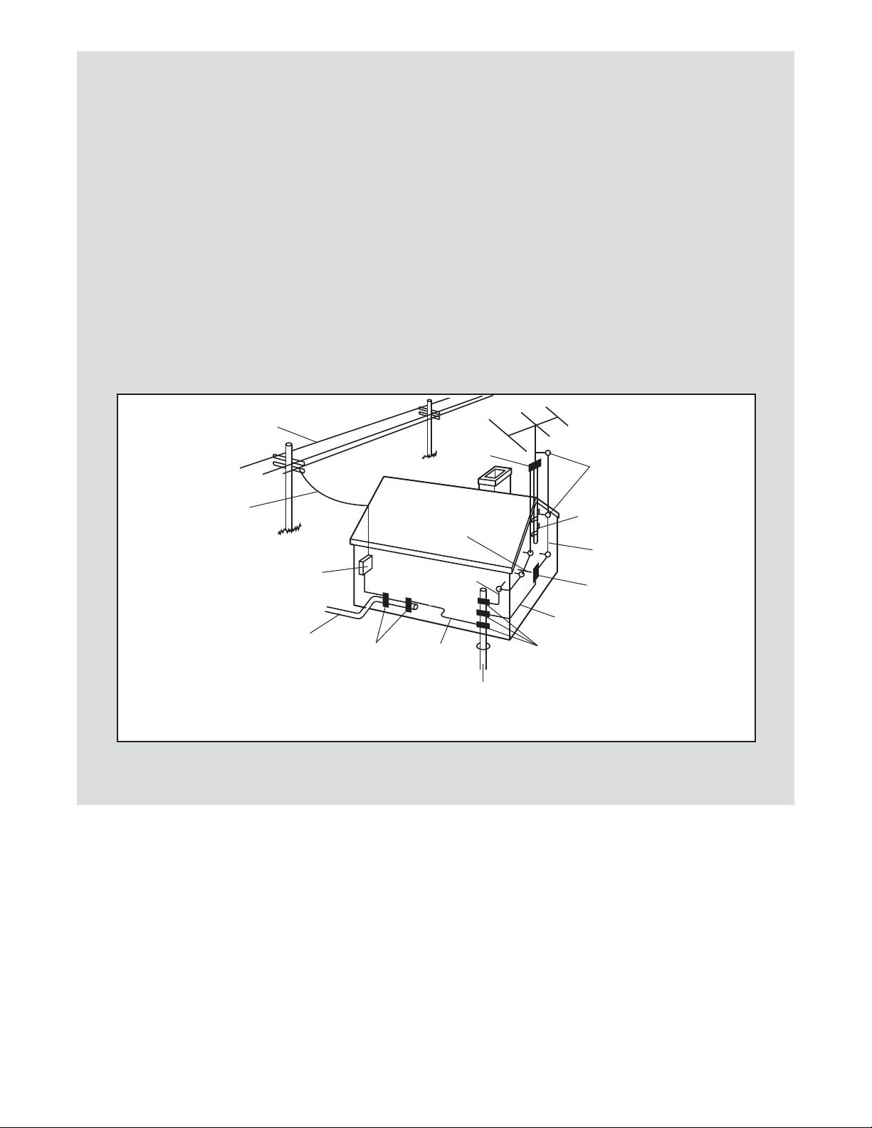
31. If an outside antenna or cable system is
connected, make sure that the antenna or
cable system is grounded to provide some
protection against voltage surges and builtup static charges. Section 810 of the National
Electrical Code, ANSI/NFPA No. 70-1984, or
your local codes and ordinances provide
information with respect to proper grounding of the mast and supporting structure,
grounding of the lead-in wire to an antenna
discharge unit, size of grounding conductors, location of antenna discharge unit,
connection to grounding electrodes, and
requirements for the grounding electrode.
26. Inspect and properly tighten all parts of the
treadmill regularly.
27. DANGER: Always unplug the power
cord immediately after use, before cleaning the treadmill, and before performing the
maintenance and adjustment procedures
described in this manual. Never remove the
motor hood unless instructed to do so by an
authorized service representative. Servicing
other than the procedures in this manual
should be performed by an authorized service representative only.
32. An outside antenna system should not be
located in the vicinity of overhead power
lines or other electric light or power circuits,
or where it can fall into such power lines or
circuits. When installing an outside antenna
system, use extreme care to keep from
touching such power lines or circuits, as
contact with them might be fatal.
33. To reduce the risk of electric shock, do not
remove the cover or the back of the television. There are no user serviceable parts
inside. Refer servicing to qualified service
personnel.
4
34. Upon completion of any service or repairs to
the treadmill or the television, ask the service technician to perform safety checks to
confirm that the unit is in proper operating
condition.
38. Use a jumper wire not smaller than No. 6
AWG (13.3 mm2) copper, or the equivalent,
when a separate antenna-grounding electrode is used. See NEC Section 810-21 (j) or
your local codes and ordinances.
35. Use No. 10 AWG (5.3 mm2) copper, No. 8 AWG
(8.4 mm2) aluminum, No. 17 AWG (1.0 mm2)
copper-clad steel or bronze wire, or larger as
a ground wire.
36. Secure an antenna lead-in and ground wires
to the house with stand-off insulators spaced
from 4 to 6 feet (1.22 to 1.83 m) apart.
37. Mount an antenna discharge unit as close
as possible to where the lead-in enters the
house.
Power Lines
Service
Entrance
Conductors
Service
Entrance
Equipment
Power Service Grounding
Electrode System (e.g.
Interior Metal Water Pipe)
Ground
Clamps
To External 75 Ohm
Terminal of Treadmill
Bonding
Jumper
39. Note to CATV system installer: This reminder
is provided to call the CATV system installer’s attention to Article 820-40 of the NEC or
your local codes and ordinances that provide
guidelines for proper grounding and, in particular, specifies that the cable ground shall
be connected to the grounding system of the
building, as close to the point of cable entry
as practical.
Ground
Clamp
Ground
Wire
Ground
Clamps
Standoff
Insulators
Mast
Antenna
Lead-in Wire
Antenna
Discharge Unit
Ground Wire
Optional Antenna Grounding Electrode Driven 8
Feet (2.44 m) Into The Earth (If Required By Local
Codes). See NEC Section 810–21 (f).
SAVE THESE INSTRUCTIONS
5

6

STANDARD SERVICE PLANS
all
7
BEFORE YOU BEGIN
Thank you for selecting the revolutionary
NORDICTRACK® COMMERCIAL 2950 treadmill. The
COMMERCIAL 2950 treadmill offers an impressive
selection of features designed to make your workouts
at home more enjoyable and effective. And when
you’re not exercising, the unique treadmill can be
folded up, requiring less than half the floor space of
other treadmills.
For your benefit, read this manual carefully before
using the treadmill. If you have questions after
Length: 6 ft. 10 in. (208 cm)
Width: 3 ft. 1 in. (94 cm)
Tray
reading this manual, please see the front cover of this
manual. To help us assist you, please note the product
model number and serial number before contacting us.
The model number and the location of the serial number decal are shown on the front cover of this manual.
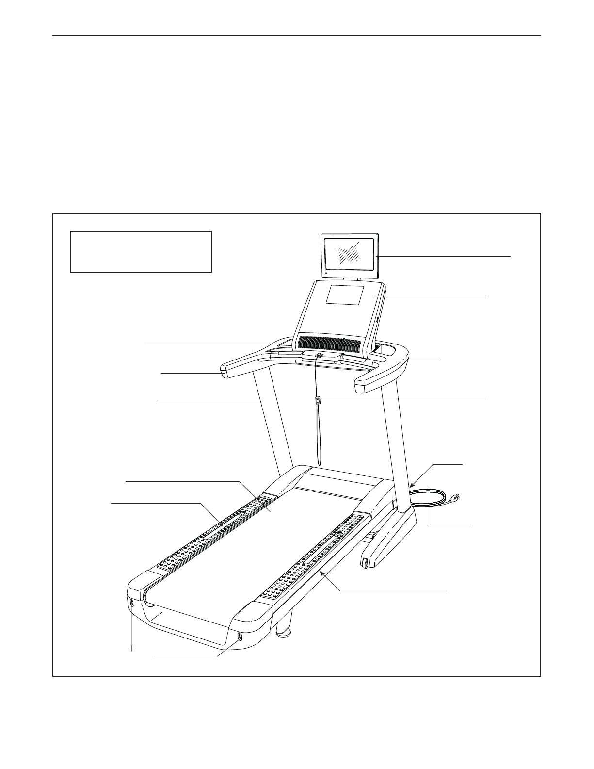
Before reading further, please review the drawing
below and familiarize yourself with the labeled parts.
TV
Console
Walking Belt
Foot Rail
Handrail
Upright
Heart Rate Monitor
Key/Clip
Power Switch
Power Cord
Platform Cushion
Idler Roller
Adjustment Screws
8
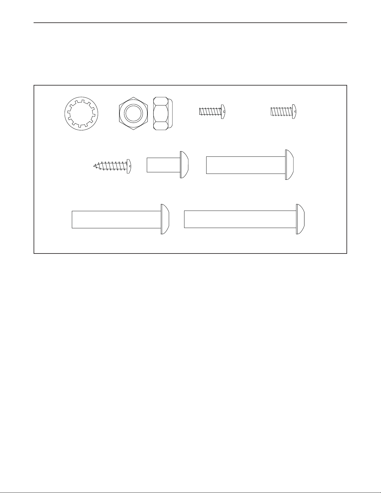
PART IDENTIFICATION CHART
Use the drawings below to identify small parts used for assembly. The number in parentheses below each drawing is the key number of the part, from the PART LIST near the end of this manual. The number following the key
number is the quantity used for assembly. Note: If a part is not in the hardware kit, check to see if it is pre-
attached. Extra parts may be included.
3/8" Star
Washer (12)–10
#8 x 3/4" Screw
3/8" x 2" Bolt (3)–1
(1)–2
3/8" Nut (11)–2
5/16" x 3/4"
Screw (125)–8
#8 x 1/2" Machine
Screw (124)–4
3/8" x 1 3/4" Bolt (6)–1
3/8" x 2 1/2" Screw (4)–2
M4 x 12mm
Screw (126)–4 (Dull black)
9
ASSEMBLY
• Assembly requires two persons.
• Place all parts in a cleared area and remove the
packing materials. Do not dispose of the packing
materials until you fi nish all assembly steps.
• After shipping, there may be an oily substance
on the exterior of the treadmill. This is normal. If
there is an oily substance on the treadmill, wipe
it off with a soft cloth and a mild, non-abrasive
cleaner.
1. Go to www.nordictrackservice.com/
registration on your computer and register
your product.
• activates your warranty
• saves you time if you ever need to contact
Customer Care
• allows us to notify you of upgrades and offers
Note: If you do not have Internet access, call
Customer Care (see the front cover of this
manual) and register your product.
• To identify small parts, see page 9.
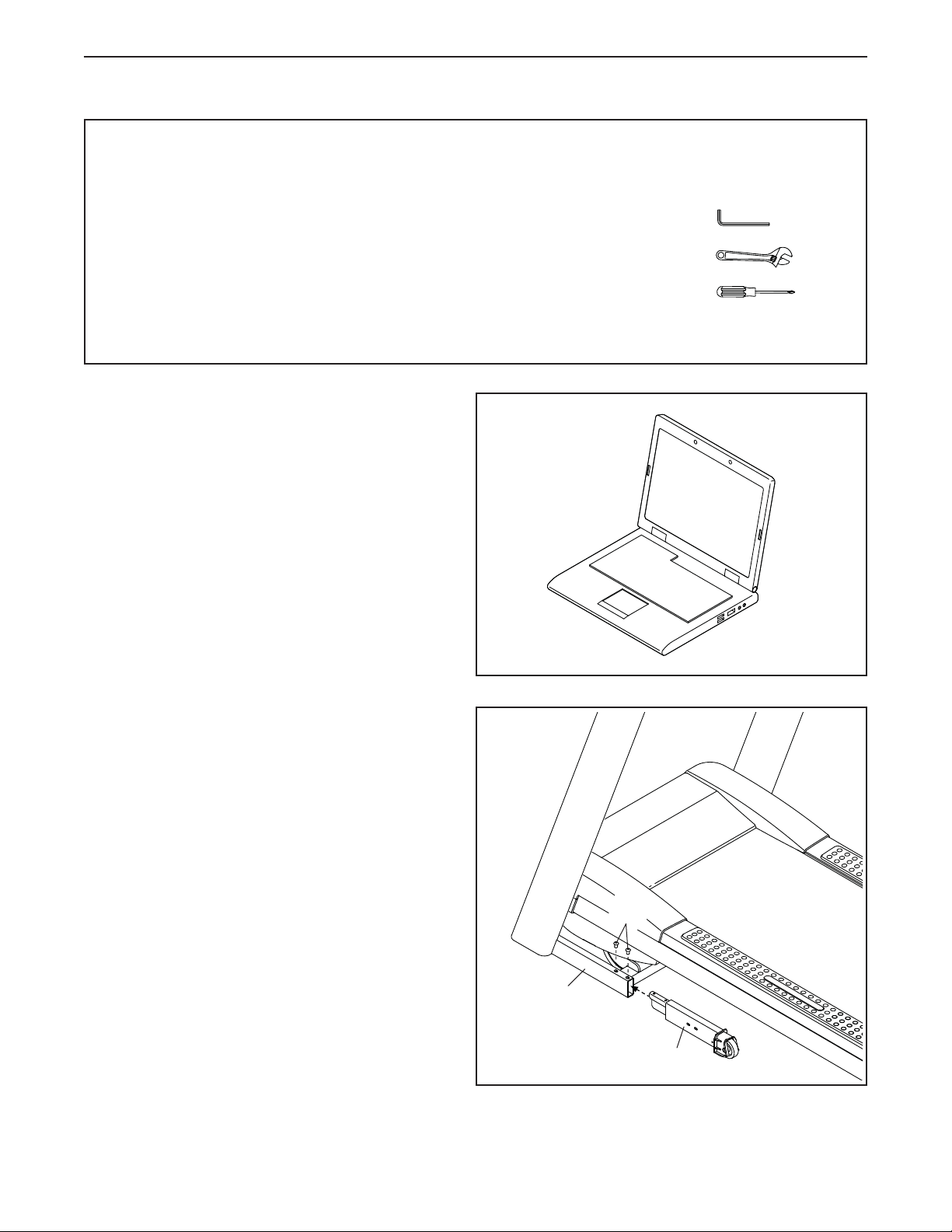
• Assembly requires the following tools:
the included hex key
one adjustable wrench
one Phillips screwdriver
To avoid damaging parts, do not use power tools.
1
2. Make sure that the power cord is unplugged.
Attach the Left Extension Leg (89) to the left
Upright (97) with two 5/16" x 3/4" Screws (125).
2
125
97
89
10
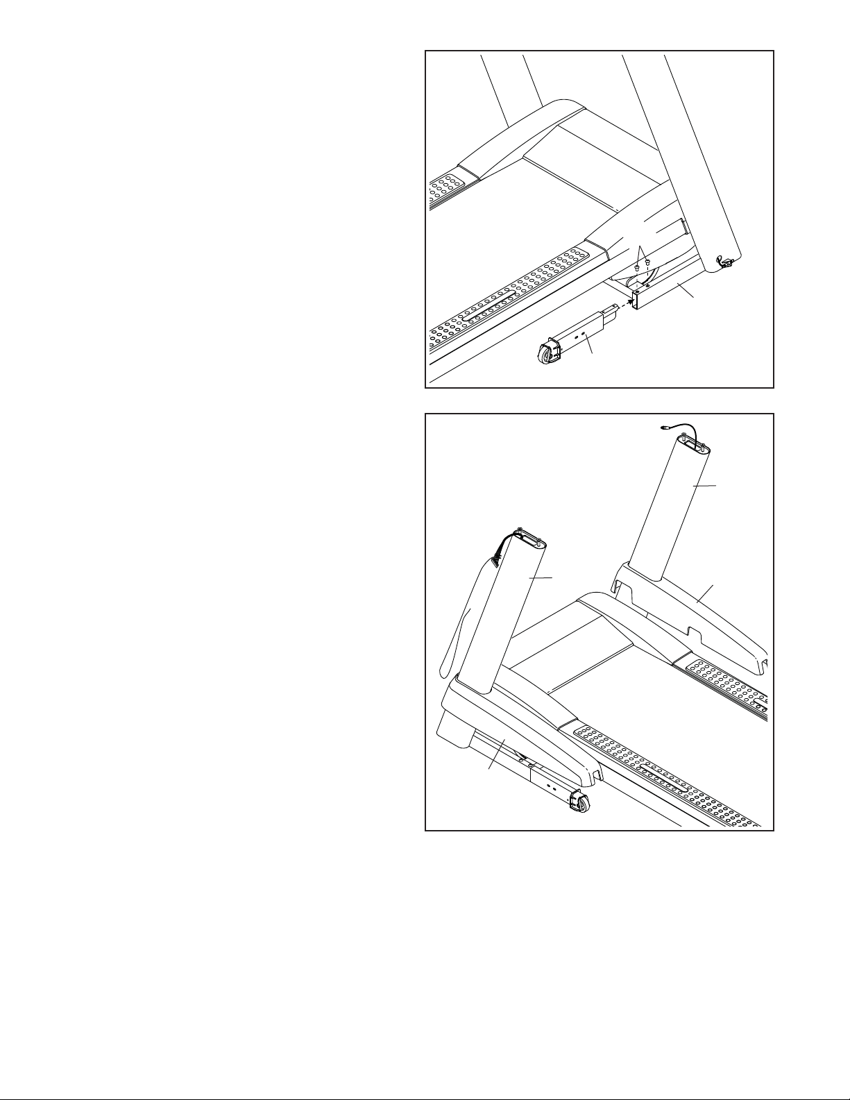
3. Attach the Right Extension Leg (90) to the right
Upright (97) with two 5/16" x 3/4" Screws (125).
3
125
97
90
4. Identify the Left and Right Base Covers (92, 93).
Slide the Left and Right Base Covers onto the
left and right Uprights (97).
4
97
97
92
93
11
5. Set the handrail assembly face down on a
soft surface to avoid scratching the handrail
assembly.
Remove and save the two 3/8" x 2" Bolts (3) and
the Handrail Bracket (85) from each side of the
handrail assembly. The Bolts and the Handrail
Brackets will be used in later steps.
5
3
85
Handrail Assembly
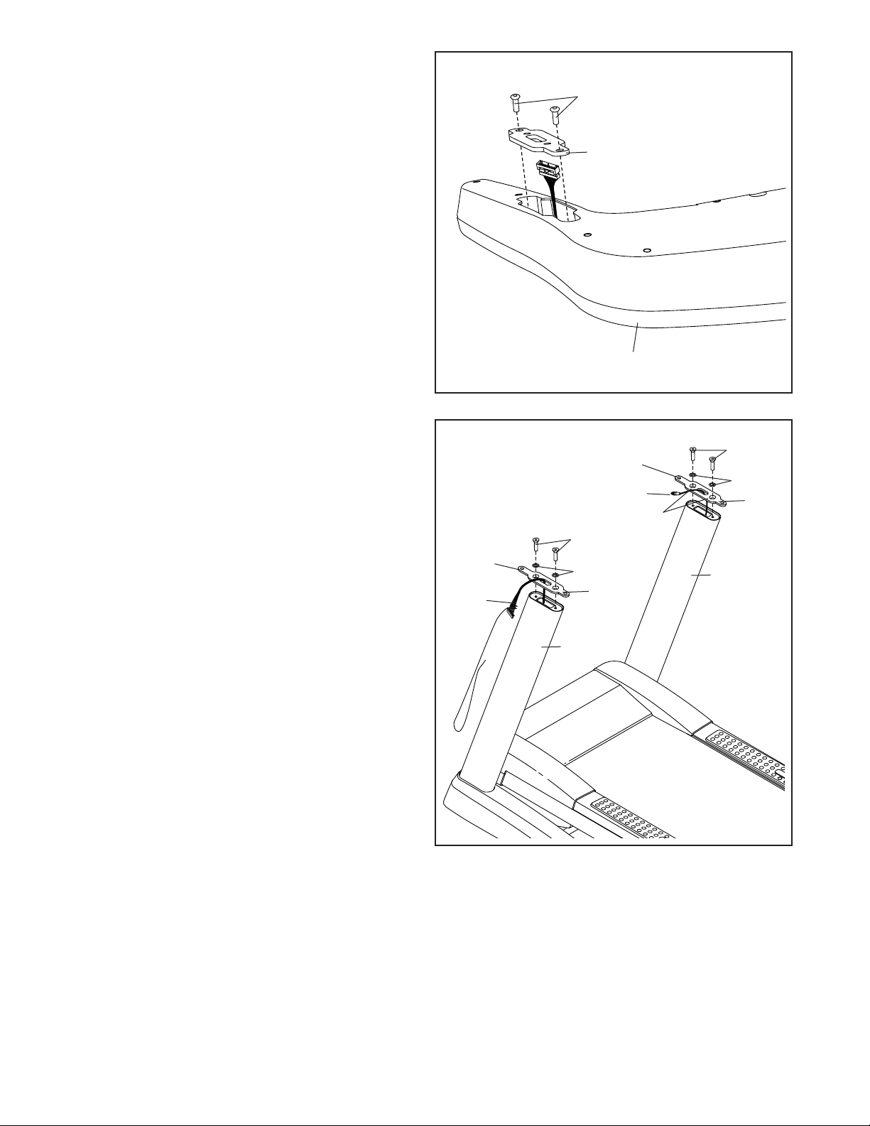
6. Remove the four 3/8" x 1" Screws (2) from the
Uprights (97).
Orient each Handrail Bracket (85) so that the
long tab is in the position shown and the large
holes are on top. Route the Upright Wire (84)
and the Upright Coaxial Cable (115) through the
center hole in each Handrail Bracket.
Attach each Handrail Bracket (85) with the two
3/8" x 1" Screws (2) and two 3/8" Star Washers
(12). Start all four Screws, and then tighten
them.
6
Long
Ta b
84
97
2
12
85
Long
Ta b
115
Large
Holes
2
12
85
97
12
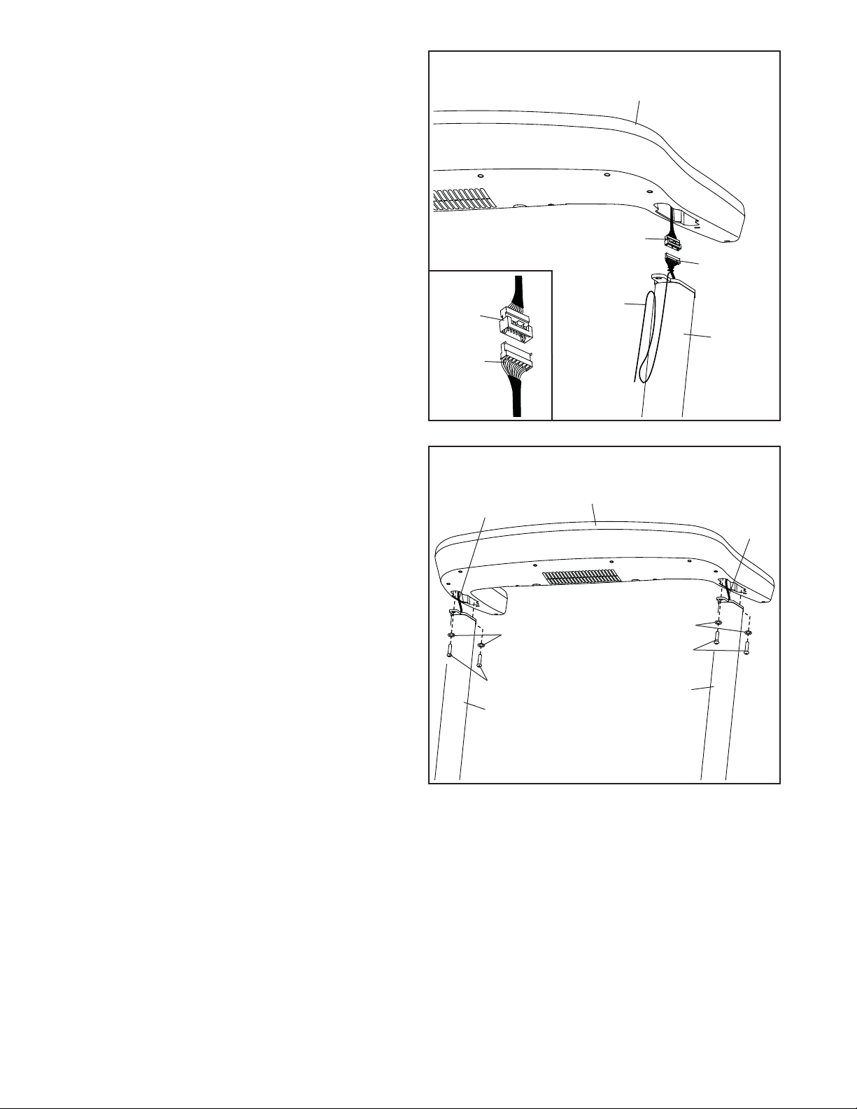
7. With the help of a second person, hold the hand-
rail assembly near the left Upright (97).
Connect the Upright Wire (84) to the Handrail
Wire (86). See the inset drawing. The connec-
tors should slide together easily and snap
into place. If they do not, turn one connector
and try again. IF YOU DO NOT CONNECT THE
CONNECTORS PROPERLY, THE CONSOLE
MAY BECOME DAMAGED WHEN YOU TURN
ON THE POWER. Then, remove the wire tie
from the Upright Wire.
7
Handrail
Assembly
86
Repeat with the Coaxial Cables on the other
side (not shown).
8. Insert the wires and cables into the Uprights
(97) as you set the handrail assembly on the
Uprights. Be careful not to pinch the wires
and cables.
Attach the handrail assembly with the four 3/8" x
2" Bolts (3) that you removed in step 5 and four
3/8" Star Washers (12). Start all four Bolts, and
then tighten them.
8
86
84
Cables
12
84
Wire
Tie
97
Handrail
Assembly
Wires
12
3
13
3
97
97
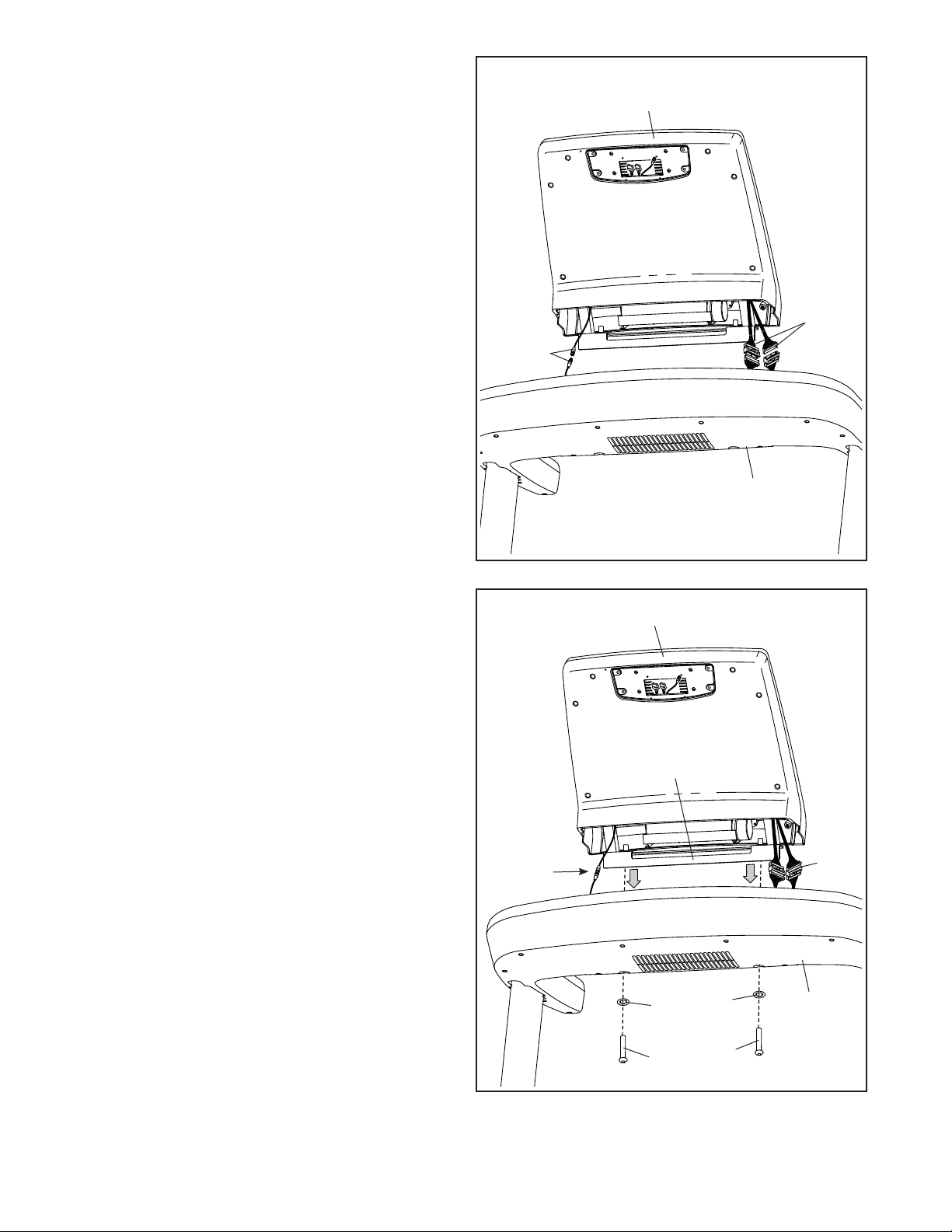
9. With the help of a second person, hold the con-
sole assembly near the handrail assembly. Be
careful not to pull on the wires during
assembly.
Connect the coaxial cables.
Connect the two wires from the handrail assem-
bly to the wires from the console assembly. The
connectors should slide together easily and
snap into place. If they do not, turn one connec-
tor and try again. IF YOU DO NOT CONNECT
THE CONNECTORS PROPERLY, THE CONSOLE MAY BECOME DAMAGED WHEN YOU
TURN ON THE POWER.
9
Coaxial
Cables
Console
Assembly
Two
Wires
Handrail
Assembly
10. Set the metal bracket on the console assembly
on the metal frame inside the handrail assembly.
Be careful not to pinch the coaxial cables or
the wires.
Attach the console assembly with two 3/8" x
2 1/2" Screws (4) and two 3/8" Star Washers
(12). Start both Screws, and then tighten
them.
10
Coaxial
Cables
Console Assembly
Metal
Bracket
12
12
Wires
Handrail
Assembly
14
4
4
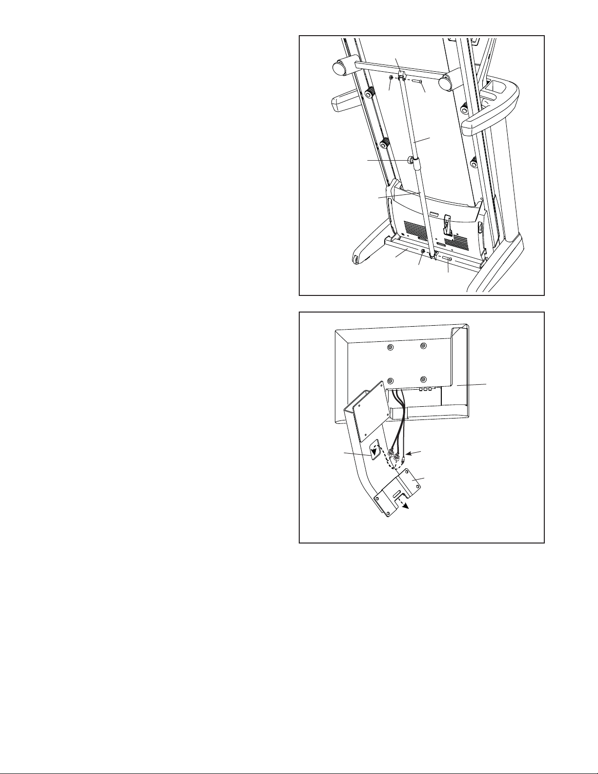
11. Raise the Frame (56) to the position shown.
Have a second person hold the Frame until
this step is completed.
11
56
Orient the Storage Latch (53) so that the large
barrel and the latch knob are in the positions
shown.
Attach the lower end of the Storage Latch (53) to
the base of the Uprights (97) with a 3/8" x 2" Bolt
(3) and a 3/8" Nut (11).
Attach the upper end of the Storage Latch (53)
to the Frame (56) with a 3/8" x 1 3/4" Bolt (6)
and a 3/8" Nut (11).
Lower the Frame (56) (see HOW TO LOWER
THE TREADMILL FOR USE on page 38).
12. Feed the three wires from the TV assembly
through the indicated hole in the TV Bracket (7).
12
Latch
Knob
Large
Barrel
11
97
11
6
53
3
Hole
TV
Assembly
Wires
7
15
 Loading...