

Model No. NTEX3196.1
Visit our website at
www.proform.com
new products, prizes,
fitness tips, and much more!
Visit our website at
www.healthrider.com
new products, prizes,
fitness tips, and much more!
Visit our website at
www.nordictrack.com
new products, prizes,
fitness tips, and much more!
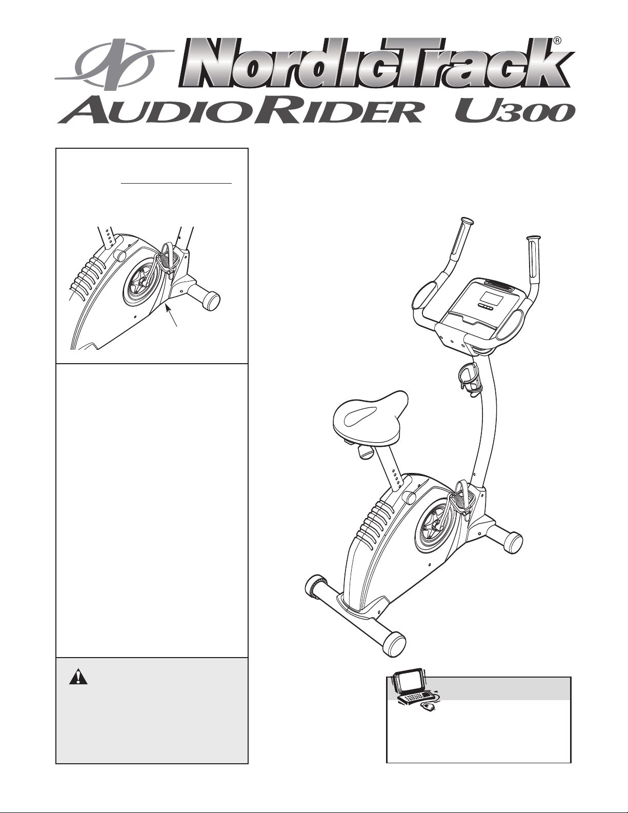
Serial No.
Write the serial number in the
space above for future reference.
Serial Number
Decal (under frame)
QUESTIONS?
As a manufacturer, we are committed to providing complete customer
satisfaction. If you have questions,
or if parts are missing, PLEASE
DO NOT CONTACT THE STORE;
please contact Customer Care.
IMPORT ANT: You must note the
product model number and
serial number (see the drawing
above) before contacting us:
USER'S MANUAL
CALL TOLL-FREE:
1-888-825-2588
Mon.–Fri., 6 a.m.–6 p.m. MST
Sat. 8 a.m.–5 p.m. MST
ON THE WEB:
www.nordictrackservice.com
CAUTION
Read all precautions and instructions in this manual before using
this equipment. Keep this manual
for future reference.
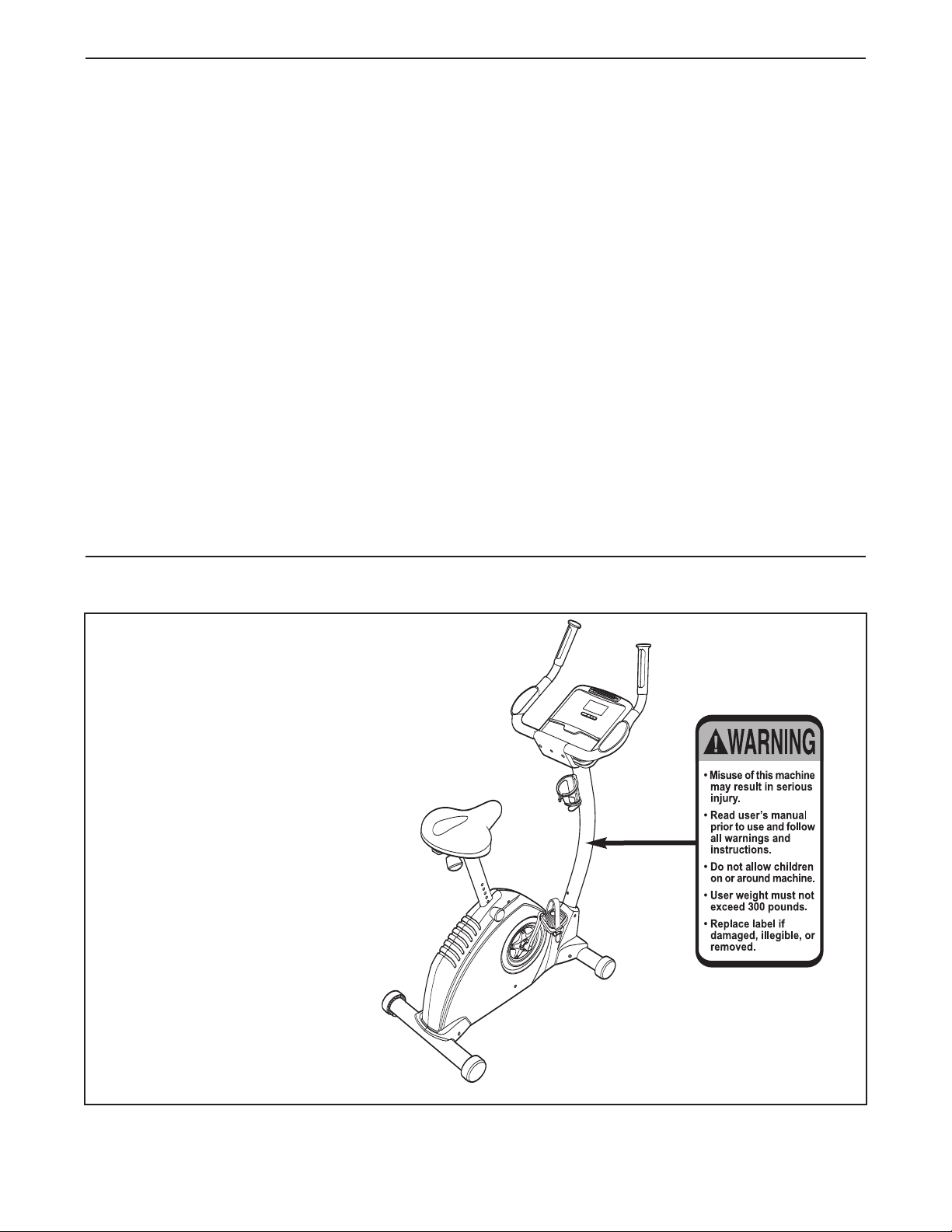
TABLE OF CONTENTS
WARNING DECAL PLACEMENT . . . . . . . . . . . . . . . . . . . . . . . . . . . . . . . . . . . . . . . . . . . . . . . . . . . . . . . . . . . . . .2
IMPORTANT PRECAUTIONS . . . . . . . . . . . . . . . . . . . . . . . . . . . . . . . . . . . . . . . . . . . . . . . . . . . . . . . . . . . . . . . .3
BEFORE YOU BEGIN . . . . . . . . . . . . . . . . . . . . . . . . . . . . . . . . . . . . . . . . . . . . . . . . . . . . . . . . . . . . . . . . . . . . . .4
ASSEMBLY . . . . . . . . . . . . . . . . . . . . . . . . . . . . . . . . . . . . . . . . . . . . . . . . . . . . . . . . . . . . . . . . . . . . . . . . . . . . . . .5
OW TO OPERATE THE EXERCISE CYCLE . . . . . . . . . . . . . . . . . . . . . . . . . . . . . . . . . . . . . . . . . . . . . . . . . . .10
H
MAINTENANCE AND TROUBLESHOOTING . . . . . . . . . . . . . . . . . . . . . . . . . . . . . . . . . . . . . . . . . . . . . . . . . . .17
EXERCISE GUIDELINES . . . . . . . . . . . . . . . . . . . . . . . . . . . . . . . . . . . . . . . . . . . . . . . . . . . . . . . . . . . . . . . . . . .18
PART LIST . . . . . . . . . . . . . . . . . . . . . . . . . . . . . . . . . . . . . . . . . . . . . . . . . . . . . . . . . . . . . . . . . . . . . . . . . . . . . .22
EXPLODED DRAWING . . . . . . . . . . . . . . . . . . . . . . . . . . . . . . . . . . . . . . . . . . . . . . . . . . . . . . . . . . . . . . . . . . . .23
ORDERING REPLACEMENT PARTS . . . . . . . . . . . . . . . . . . . . . . . . . . . . . . . . . . . . . . . . . . . . . . . . . .Back Cover
LIMITED WARRANTY . . . . . . . . . . . . . . . . . . . . . . . . . . . . . . . . . . . . . . . . . . . . . . . . . . . . . . . . . . . . . .Back Cover
WARNING DECAL PLACEMENT
The warning decal shown here has
been applied in the location shown.
If the decal is missing or illegible, call the telephone number
on the front cover of this manual
and request a free replacement
decal. Apply the decal in the
location shown.
may not be shown at actual size.
Note: The decal
NordicTrack is a registered trademark of ICON IP, Inc.
2

IMPORTANT PRECAUTIONS
WARNING:To reduce the risk of serious injury, read all important precautions and
instructions in this manual and all warnings on your exercise cycle before using your exercise
ycle. ICON assumes no responsibility for personal injury or property damage sustained by or
c
through the use of this product.
1. Before beginning any exercise program, consult your physician. This is especially important for persons over the age of 35 or persons with pre-existing health problems.
2. Us e the exercise cycle only as described in
this manual.
3. It is the responsibility of the owner to ensure
that all users of the exercise cycle are adequately informed of all precautions.
4. The exercise cycle is intended for home use
only. Do not use the exercise cycle in
a commercial, rental, or institutional setting.
5. Keep the exercise cycle indoors, away from
moisture and dust. Place the exercise cycle
on a level surface, with a mat beneath it to
protect the floor or carpet. Make sure that
there is enough clearance around the exercise cycle to mount, dismount, and use it.
6. Inspect and properly tighten all parts regularly. Replace any worn parts immediately.
7. Keep children under the age of 12 and pets
away from the exercise cycle at all times.
8. Wear appropriate clothes while exercising;
do not wear loose clothes that could become
caught on the exercise cycle. Always wear
athletic shoes for foot protection.
9. The exercise cycle should not be used by
persons weighing more than 300 lbs.
(136 kg).
10. The pulse sensor is not a medical device.
Various factors, including the user's movement, may affect the accuracy of heart rate
readings. The pulse sensor is intended only
as an exercise aid in determining heart rate
trends in general.
11. Always keep your back straight while using
the exercise cycle; do not arch your back.
12. If you feel pain or dizziness while exercising,
stop immediately and cool down.
13. The decal shown below has been placed on
the exercise cycle. If the decal is missing or
illegible, call the toll-free telephone number
on the front cover of this manual and order a
free replacement decal. Apply the decal in
the location shown.
3
BEFORE YOU BEGIN
Congratulations for selecting the revolutionary
NordicTrack
Cycling is one of the most effective exercises for
ncreasing cardiovascular fitness, building en du ran ce ,
i
nd toning the entire body. The AUDIORIDER U300
a
exercise cycle offers an impressive array of features,
including a console with two motivational interactive
games, designed to let you enjoy this healthful exercise in the comfort and convenience of your home.
For your benefit, read this manual carefully before
you use the exercise cycle. If you have questions
after reading this manual, please see the front cover
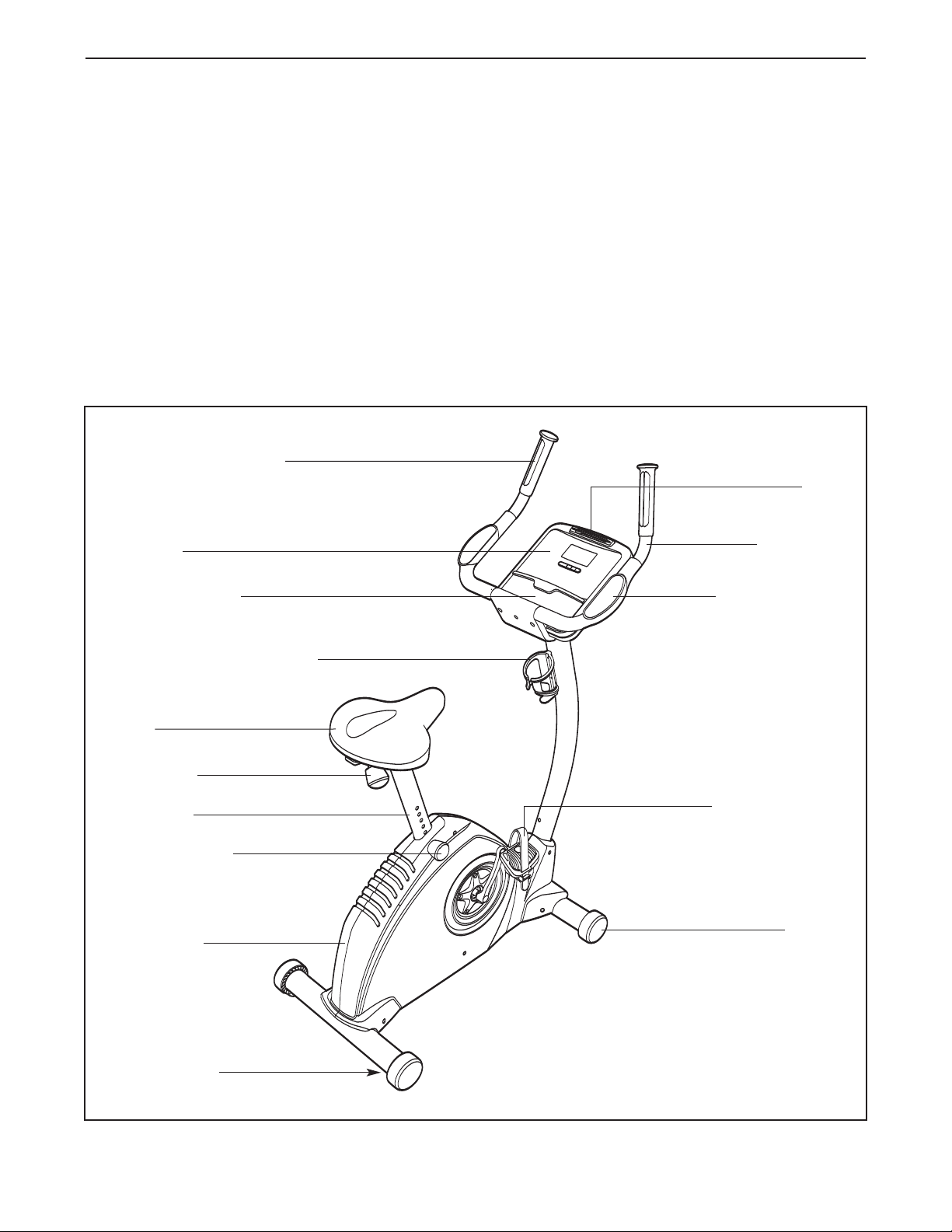
Handgrip Pulse Sensor
Console
®
AUDIORIDER U300 ex erci se c ycl e.
of this manual. To help us assist you, note the product
model number and serial number before contacting
us. The model number and the location of the serial
umber decal are shown on the front cover of this
n
anual.
m
To avoid a registration fee for any service needed
under warranty, you must register the exercise
cycle at www.wesloservice.com/registration.
Before reading further, please familiarize yourself with
the parts that are labeled in the drawing below.
Fan
Handlebar
Stereo Speakers
Water Bottle Holder
(no water bottle is included)
Seat
Seat Knob
Seat Post
Seat Post Knob
Side Shield
Padded Armrest
Pedal with Strap
Wheel
Leveling Foot
4
M10 x 85mm Button
Screw (56)–4
M10 x 50mm Button
Screw (48)–3
M6 x 10mm
Screw (60)–2
M6 x 30mm Button
Screw (46)–4
M4 x 19mm
Screw (47)–2
M10 Split
Washer (55)–3
M4 x 16mm
Screw (54)–6
M4 x 12mm
Screw (64)–1
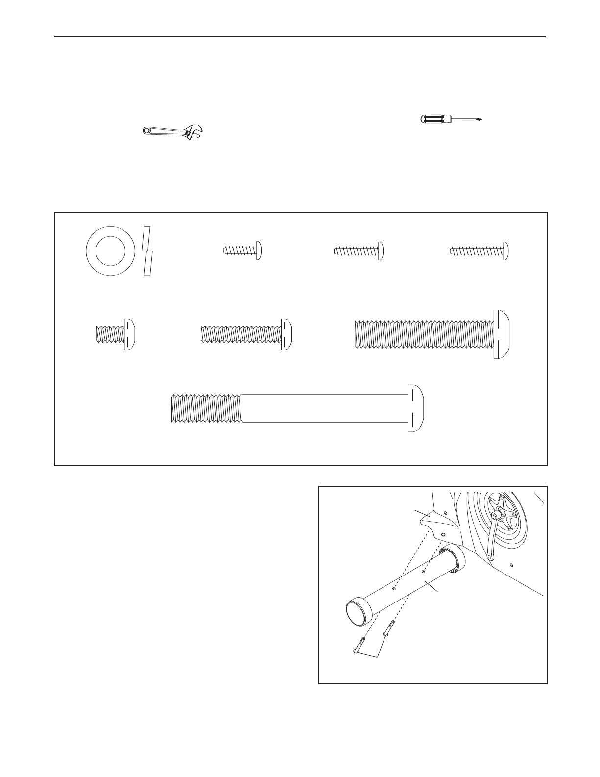
ASSEMBLY
lace all parts of the exercise cycle in a cleared area and remove the packing materials. Do not dispose of the
P
packing materials until assembly is completed.
In addition to the included hex keys, assembly requires a phillips screwdriver and an
adjustable wrench .
As you assemble the exercise cycle, use the drawings below to identify small parts. The number in parentheses
below each drawing is the key number of the part, from the PART LIST near the end of this manual. The number
following the parentheses is the quantity used in assembly. Note: Some small parts may have been pre-
assembled for shipping. If a part is not in the parts bag, check to see if it has been preassembled.
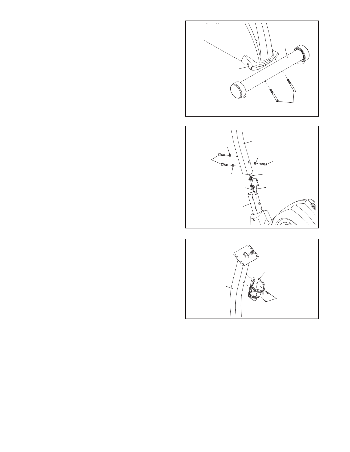
1. Attach the Front Stabilizer (2) to the Frame (1) with
two M10 x 85mm Button Screws (56).
1
5
1
56
2
2. Attach the Rear Stabilizer (3) to the Frame (1) with
two M10 x 85mm Button Screws (56).
2
3
1
56
3. While another person holds the Handlebar Post (6)
near the Frame (1), connect the Upper Wire
Harness (51) to the Lower Wire Harness (50) and
the Power Jack Wire (65). Next, pull the excess
Upper Wire Harness out of the top of the Handlebar
Post, and slide the Handlebar Post onto the Frame.
Be careful not to pinch the Wire Harnesses.
Attach the Handlebar Post (6) to the Frame (1) with
three M10 x 50mm Button Screws (48) and three
M10 Split Washers (55); tighten the two Button
Screws in the front of the Handlebar Post first,
and then tighten the third Button Screw.
4. Attach the Water Bottle Holder (18) to the
Handlebar Post (6) with two M4 x 19mm
Screws (47).
3
50
1
6
55
48
51
65
18
55
48
55
4
6
47
6

5. The Console (9) requires four 1.5V “D” batteries
not included); alkaline batteries are recommended.
(
IMPORTANT: If the exercise cycle has been
xposed to cold temperatures, allow it to warm
e
to room temperature before inserting batteries
into the Console. If you do not do this, the console displays or other electronic components
ay become damaged. Press the tabs on the bat-
m
ery covers and remove the battery covers. Next,
t
insert four batteries into the Console;
that the batteries are oriented as shown by the
diagrams inside the Console.
battery covers.
Note: The Console (9) can be operated with an
optional power supply instead of batteries. To pur-
chase a power supply, call the toll-free telephone number on the front cover of this manual.
Plug one end of the power supply into the jack at
the front of the exercise cycle. Plug the other end of
the power supply into an appropriate outlet that is
properly installed in accordance with all local codes
and ordinances.
make sure
Then, reattach the
5
Batteries
attery
B
overs
C
atteries
B
9
6. Attach the Handlebar (7) to the Handlebar Post (6)
with four M6 x 30mm Button Screws (46). Be care-
ful to avoid pinching the wires in the Handlebar
and the Handlebar Post.
6
46
7
6
7
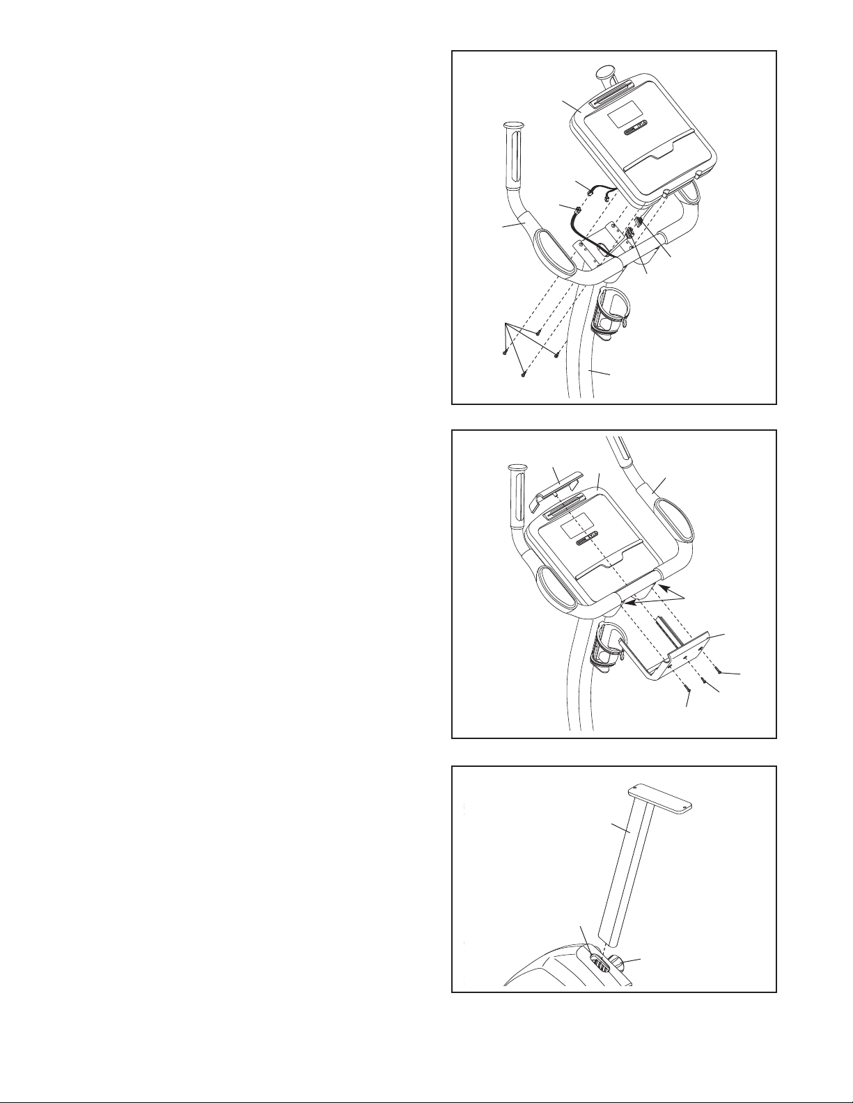
7. While another person holds the Console (9) near
he Handlebar (7), connect the wire harness on the
t
Console to the Upper Wire Harness (51). Next, con-
ect the pulse wire on the Console to the Pulse
n
Grip Wire (10). Note: The remaining wire on the
Console is used during the manufacturing process;
disregard this wire.
nsert the excess wiring downward into the
I
Handlebar Post (6). Attach the Console (9) to the
Handlebar (7) with four M4 x 16mm Screws (54).
Be careful to avoid pinching the wires.
7
9
Pulse
Wire
10
7
Wire Harness
51
54
6
8. Slide the Bottom Handlebar Cover (33) into the
slots in the bottom of the Console (9). Attach the
Bottom Handlebar Cover to the Handlebar (7) and
the Top Handlebar Cover (30) with two M4 x 16mm
Screws (54) and one M4 x 12mm Screw (64).
9. Turn the Seat Post Knob (20) counterclockwise several turns to loosen it. Next, pull the Seat Post Knob
outward, and insert the Seat Post (11) into the
Frame (1). Slide the Seat Post upward or downward
to the desired position, and release the Seat Post
Knob. Move the Seat Post up or down slightly to
make sure that the Seat Post Knob is engaged
in one of the adjustment holes in the Seat Post.
Then, turn the Seat Post Knob clockwise to tighten it.
8
30
9
9
11
1
7
Slot
33
54
64
54
20
8
 Loading...