

Page 1
CAUTION
Read all precautions and instructions in this manual before using
this equipment. Save this manual
for future reference.
Model No. NTSY39210
Serial No.
Write the serial number in the
space above for future reference.
Serial Number Decal
(Behind Backrest)
QUESTIONS?
As a manufacturer, we are committed to providing complete
customer satisfaction. If you
have questions, or if there are
missing or damaged parts, we
will guarantee complete satisfaction through direct assistance from our factory.
TO AVOID DELAYS, PLEASE
CALL DIRECT TO OUR TOLLFREE CUSTOMER HOT LINE.
The trained technicians on our
customer hot line will provide
immediate assistance, free of
charge.
CUSTOMER HOT LINE:
1-888-825-2588
Mon.–Fri., 6 a.m.–6 p.m. MST
USER’S MANUAL
Visit our website at
www.nordictrack.com
new products, prizes,
fitness tips, and much more!
Page 2

2
IMPORTANT PRECAUTIONS . . . . . . . . . . . . . . . . . . . . . . . . . . . . . . . . . . . . . . . . . . . . . . . . . . . . . . . . . . . . . 3
BEFORE YOU BEGIN . . . . . . . . . . . . . . . . . . . . . . . . . . . . . . . . . . . . . . . . . . . . . . . . . . . . . . . . . . . . . . . . . . . 4
ASSEMBLY . . . . . . . . . . . . . . . . . . . . . . . . . . . . . . . . . . . . . . . . . . . . . . . . . . . . . . . . . . . . . . . . . . . . . . . . . . . 5
ADJUSTMENTS . . . . . . . . . . . . . . . . . . . . . . . . . . . . . . . . . . . . . . . . . . . . . . . . . . . . . . . . . . . . . . . . . . . . . . 10
CABLE DIAGRAM . . . . . . . . . . . . . . . . . . . . . . . . . . . . . . . . . . . . . . . . . . . . . . . . . . . . . . . . . . . . . . . . . . . . .11
WEIGHT RESISTANCE CHART . . . . . . . . . . . . . . . . . . . . . . . . . . . . . . . . . . . . . . . . . . . . . . . . . . . . . . . . . . .11
ORDERING REPLACEMENT PARTS . . . . . . . . . . . . . . . . . . . . . . . . . . . . . . . . . . . . . . . . . . . . . . . .Back Cover
LIMITED WARRANTY . . . . . . . . . . . . . . . . . . . . . . . . . . . . . . . . . . . . . . . . . . . . . . . . . . . . . . . . . . . Back Cover
Note: APART IDENTIFICATION CHART and a PART LIST/EXPLODED DRAWING are attached in the center of
this manual. Remove the PART IDENTIFICATION CHART and PART LIST/EXPLODED DRAWING before beginning assembly.
NordicTrack is a registered trademark of ICON Health & Fitness, Inc.
TABLE OF CONTENTS
Page 3
1. Read all instructions in this manual before
using the weight system. Use the weight system only as described in this manual.
2. It is the responsibility of the owner to make
that all users of the weight system are adequately informed of all precautions.
3. The weight system is intended for home use
only. Do not use the weight system in any
commercial, rental, or institutional setting.
4. Use the weight system only on a level surface. Cover the floor beneath the weight system to protect the floor.
5. Make sure that all parts are properly tight-
ened each time you use the weight system.
Replace any worn parts immediately.
6. Keep children under 12 and pets away from
the weight system at all times.
7. Keep hands and feet away from moving parts.
8. Make sure that the cables remain on the pulleys at all times. If the cables bind as you are
exercising, stop immediately and make sure
that the cables are on the pulleys.
9. Always wear athletic shoes for foot protection while exercising.
10. The weight system is designed to support a
maximum user weight of 300 pounds.
11. Make sure that the weight pin is fully inserted
into the weight stack before you exercise.
12. If you feel pain or dizziness while exercising,
stop immediately and begin cooling down.
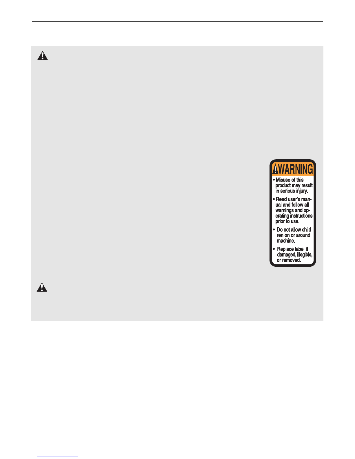
13. The decal shown here
has been placed on the
weight system in the
location shown on page
4. If the decal is missing
or illegible, call our tollfree Customer Hot Line
at 1-888-825-2588 and
order a free replacement
decal. Apply the decal in
the location shown.
WARNING:Before beginning this or any exercise program, consult your physician. This
is especially important for persons over the age of 35 or persons with pre-existing health problems.
Read all instructions before using. ICON assumes no responsibility for personal injury or property
damage sustained by or through the use of this product.
WARNING: To reduce the risk of serious injury, read the following important precautions
before using the weight system.
IMPORTANT PRECAUTIONS
3
Warning Decal
Page 4
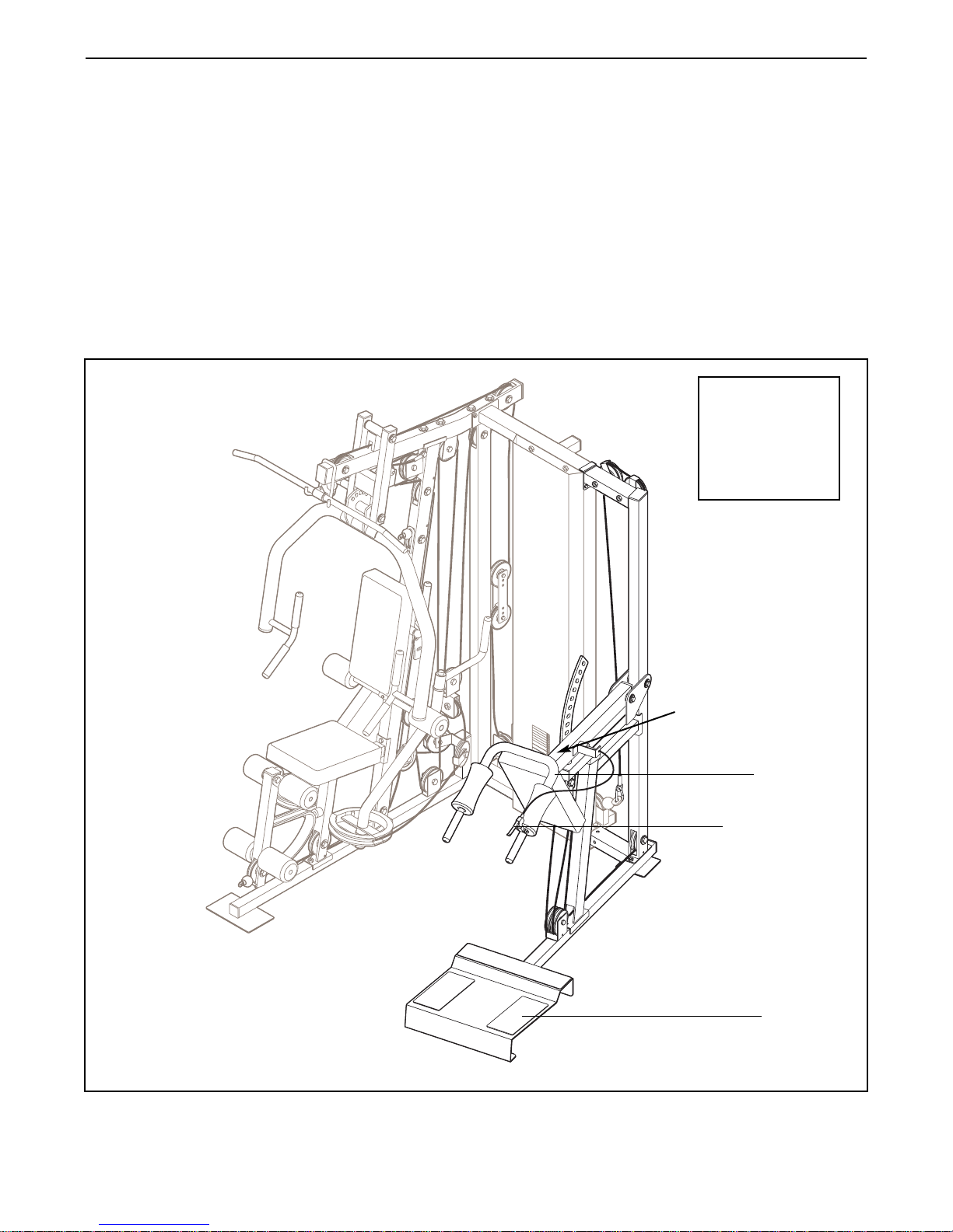
4
Release Handle
Foot Plate
Hack Squat
Warning
Decal
BEFORE YOU BEGIN
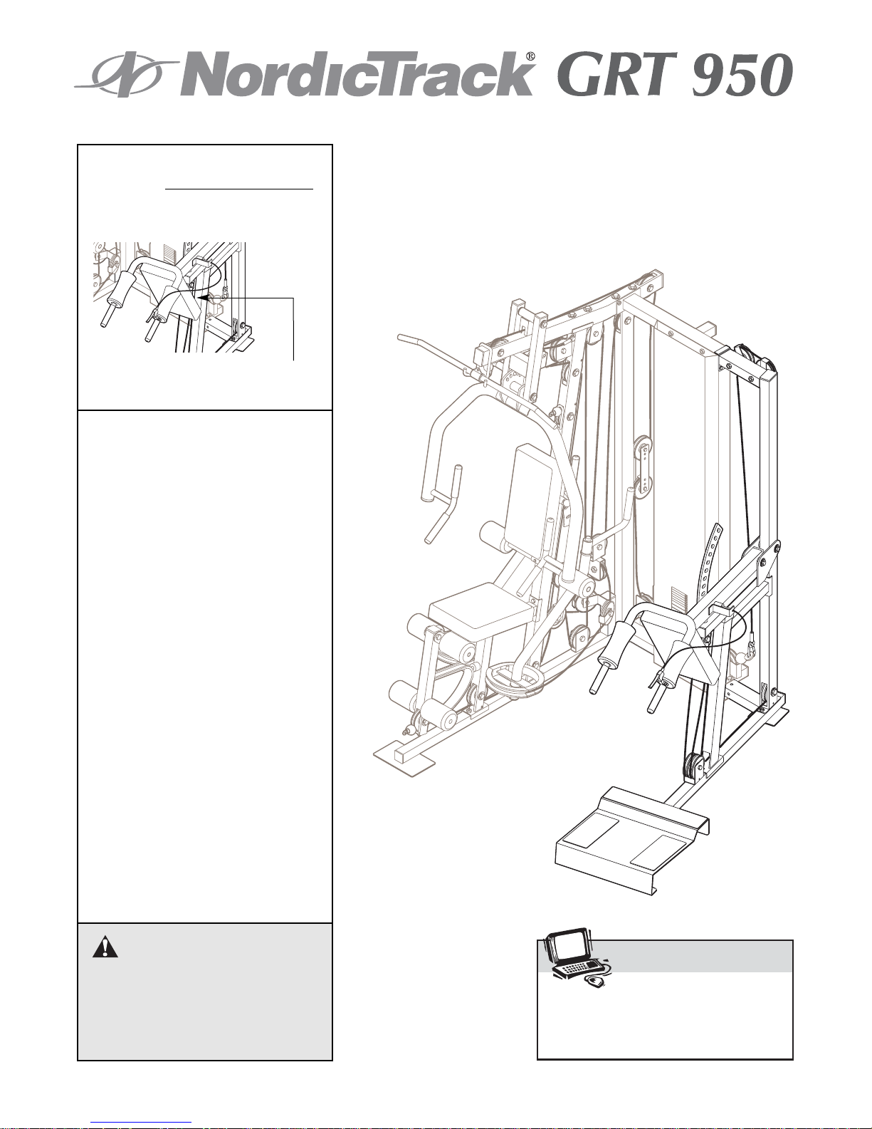
Thank you for selecting the versatile NordicTrack
®
GRT 950 weight system attachment. The weight system attachment is designed to develop the muscle
groups of the lower body. Whether your goal is to tone
your body, build dramatic muscle size and strength, or
improve your cardiovascular system, the attachment
will help you to achieve the specific results you want.
For your benefit, read this manual carefully before
using the weight system attachment. If you have
additional questions, please call our Customer Service
Department toll-free at 1-888-825-2588, Monday
through Friday, 6 a.m. until 6 p.m. Mountain Time
(excluding holidays). To help us assist you, please note
the product model number and serial number before
calling. The model number is NTSY39210. The serial
number can be found on a decal attached to the
attachment (see the front cover of this manual).
Before reading further, please review the drawing
below and familiarize yourself with the parts that are
labeled.
ASSEMBLED
DIMENSIONS:
Height: 84 in.
Width: 86 in.
Length: 72 in.
Page 5

5
Make sure you have the following tools:
• Two adjustable wrenches
• One standard screwdriver
• One phillips screwdriver
• One rubber mallet
•You will also need grease or petroleum jelly, a
small amount of soapy water, and clear tape or
masking tape.
Note: Assembly will be more convenient if you have
a socket set, a set of open-end or closed-end
wrenches, or a set of ratchet wrenches.
How to Identify Parts
To help you identify the small parts used in assembly,
we have included a PART IDENTIFICATION CHART
in the center of this manual. Place the chart on the
floor and use it to easily identify parts during each
assembly step. Note: Some small parts may have
been pre-attached. If a part is not in the parts
bag, check to see if it has been pre-attached.
How to Orient Parts
As you assemble the weight system, make sure that
all parts are oriented exactly as shown in the drawings.
Tightening Parts
Tighten all parts as you assemble them, unless
instructed to do otherwise.
Questions?
If you have questions after reading the assembly
instructions, please call our Customer Service
Department at 1-888-825-2588.
Assembly Requires Two Persons
For your convenience and safety, assemble the
weight system with the help of another person.
Set Aside Enough Time
Due to the many features of the weight system, the
assembly process will take a few hours. By setting
aside plenty of time and by deciding to make the
task enjoyable, assembly will go smoothly. You may
want to assemble the weight system over a couple
of evenings.
Select a Location for the Weight System
Because of its weight and size, the weight system
should be assembled in the location where it will be
used. Make sure that there is enough room to walk
around the weight system as you assemble it.
How to Unpack the Box
To make assembly as easy as possible, we have
divided the assembly process into four stages. The
parts needed for each stage are found in individual
bags. Important: Wait until you begin each stage
to open the parts bag for that stage. Place all
parts of the weight system in a cleared area and
remove the packing materials. Do not dispose of
the packing materials until assembly is completed.
Make Assembly Easier for Yourself
Everything in this manual is designed to
ensure that the weight system can be assembled successfully by most people. Before
beginning assembly, make sure to read the
information on this page. This brief introduction will save you much more time than
it takes to read it.
The Four Stages of the Assembly Process
Frame Assembly—You will begin by assembling
the base and the uprights that form the skeleton of
the weight system.
Arm Assembly—During this stage you will
assemble the arms and the leg lever.
Cable Assembly—During this stage you will
attach the cables and pulleys that connect the
arms to the weights.
Seat Assembly—During the final stage you will
assemble the seats and the backrests.
ASSEMBLY
Page 6

6
3. Press a 75mm x 50mm Inner Cap (21) into the
top of the Hack Squat Upright (4).
Remove the indicated two M10 x 45mm bolts (E),
two M10 washers (F), and two M10 Nylon
Locknuts (C) from the left upright (G).
Attach the Hack Squat Upright (4) to the two M10
x 67mm Carriage Bolts (33) in the Hack Squat
Base (1) with two M10 Locknuts (32). Do not
tighten the Locknuts yet.
Attach the Hack Squat Upright (4) to the left
upright (G) with two M10 x 50mm Bolts (39) and
two M10 Nylon Locknuts (C).
2. Press a 50mm Square Inner Cap (25) into the
indicated end of the Hack Squat Base (1).
Insert four M10 x 67mm Carriage Bolts (33) up
through the bottom of the Hack Squat Base (1).
Slide the Hack Squat Base into the rear base (C).
Note: If the Bolts fall out, stick a piece of tape
over the bolt heads to hold them in.
Secure the Hack Squat Base (1) to the rear base
(D) with four M10 x 25mm Bolts (31).
1.
Remove the 50mm x 75mm inner cap w/ slot (A),
the four M10 x 67mm carriage bolts (B), and the
four M10 nylon locknuts (C) from the rear base
(D).
Before beginning assembly, make sure that
you understand the information on page 5.
This brief introduction will save you much
more time than it takes to read it.
Frame Assembly
1
C
D
BB
33
25
31
D
1
A
3
33
32
4
21
32
33
1
G
F
E
C
39
2
Page 7

7
4. Press the 75mm x 50mm Spacer (48) into the
82mm x 57mm Outer Cap (26). Press the Outer
Cap onto the Hack Squat Leg (2).
Attach the Hack Squat Leg (2) to the two M10 x
67mm Carriage Bolts (33) in the Hack Squat
Base (1) with two M10 Locknuts (32).
Attach the Hack Squat Leg (2) to the Hack Squat
Upright (4) with two M10 x 95mm Bolts (38), two
M10 Washers (36), and two M10 Locknuts (32).
Tighten the M10 Locknuts (32) used in steps 3
and 4.
4
4
38
26
48
2
32
32
32
33
1
36
5
6
7
21
21
30
3
15
31
5
21
22
7
9
8
42
42
10
28
13
13
31
13
14
14
16
29
37
5. Press two 75mm x 50mm Inner Caps (21) into
the Hack Squat Bracket (3). Press four 34mm
Bushings (14) into the Hack Squat Bracket.
Attach the Hack Squat Bumper (16) to the Hack
Squat Bracket (3) with an M4 Washer (37) and an
M4 x 20mm Screw (29).
Arm Assembly
7. Press a 75mm x 50mm Inner Cap (21) into the
end of the Hack Squat Frame (5). Press a 50mm
x 40mm Inner Cap (22) into the bottom of the
backrest tube on the Frame. Press two 34mm x
19mm Bushings (13) into the Hack Squat Frame.
Slide two Foam Pads (7) onto the Hack Squat
Frame (5).
Attach the Release Handle (10) to the Hack
Squat Frame (5) with an M6 x 25mm Allen Head
Screw (28).
Slide the Handgrip (8) and the Long Handgrip (9)
onto the indicated handles of the Hack Squat
Frame (5). Press two 25mm Round Inner Caps
(42) into the handles on the Frame.
6. Press two 34mm x 19mm Bushings (13) into the
Hack Squat Upright (4).
Attach the Hack Squat Bracket (3) to the Hack
Squat Upright (4) with a 25mm x 86mm Pivot Rod
(15), two M10 Large Washers (30), and two M10
x 25mm Bolts (31).
32
30
13
Page 8

8
8. Attach the Hack Squat Frame (5) to the Hack
Squat Bracket (3) with a 25mm x 86mm Pivot
Rod (15), two M10 Large Washers (30), and two
M10 x 25mm Bolts (31).
Squeeze the Release Handle (10) and align the
Hack Squat Pin (12) with a hole in the arm on the
Hack Squat Bracket (3). Let go of the Release
Handle so that the Hack Squat Pin engages the
hole.
8
9
15
30
30
12
5
31
31
10
Arm
3
10. Wrap the Hack Squat Cable (20) around a Pulley
(19). Attach the Pulley, along with another Pulley,
inside the bracket on the Hack Squat Base (1)
with an M10 x 70mm Bolt (40) and an M10
Locknut (32).
11. Route the Hack Squat Cable (20) over the
Pulley (19) attached to the Hack Squat Bracket
(3) in step 9. Make sure that the Cable is routed
over the Pulley from the back to the front.
9. Locate the Hack Squat Cable (20). Attach the
Cable and a Pulley (19) to the Hack Squat
Bracket (3) with an M10 x 60mm Bolt (24), four
M10 Washers (36), and an M10 Locknut (32).
10
11
19
20
36
36
24
19
32
40
1
Bracket
20
20
19
3
Cable Assembly
32
3
Page 9

9
12. Route the Hack Squat Cable (20) around the
other Pulley (19) attached to the Hack Squat
Base (1) in step 10, and through the Hack Squat
Leg (2).
14. Wrap the Hack Squat Cable (20) around a Pulley
(19). Attach the Pulley and a Cable Trap (18) to
the left hole in the top of the Hack Squat Upright
(4) with an M10 x 125mm Bolt (41), a 15mm x
8mm Spacer (46), an M10 Washer (36), and an
M10 Locknut (32).
Wrap the Hack Squat Cable (20) around another
Pulley (19). Attach the Pulley and a Cable Trap
(18) to the other hole in the Hack Squat Upright
(4) in the same manner.
Make sure the Cable Traps (18) are positioned
to hold the Hack Squat Cable (20) in the
grooves of the Pulleys (19).
15. Attach the end of the Hack Squat Cable (20) to
the end of the rear cable (F) with a Cable Clip
(34).
13. Route the Hack Squat Cable (20) under a Pulley
(19) and through the Hack Squat Upright (4).
Attach the Pulley inside the Upright with an M10 x
65mm Bolt (35), two 15mm x 12mm Spacers (17),
two M10 Washers (36), and an M10 Locknut (32).
12
13
14
15
20
20
17
19
36
35
2
1
19
4
4
20
41
19
18
18
46
Left
Hole
46
32
36
36
20
F
34
40
32
Page 10

This section explains how to adjust the weight system attachment. Make sure all parts are properly tightened each
time you use the weight system. Replace any worn parts immediately. The weight system can be cleaned with a
damp cloth and a mild, non-abrasive detergent. Do not use solvents.
10
ADJUSTMENTS
5
12
3
Foot
Plate
10
7
1
Adjustment
Holes
ADJUSTING THE HACK SQUAT
Stand on the foot plate on the Hack Squat Base (1)
with your shoulders under the Foam Pads (7).
Squeeze the Release Handle (10) and move the
Hack Squat Frame (5) to the desired position.
Release the Handle, and engage the Hack Squat Pin
(12) into an adjustment hole in the Hack Squat
Bracket (3).
WARNING:Make sure the Hack
Squat Pin (12) fully engages the Hack Squat
Bracket (3) before you use the Hack Squat.
16. Attach the Hack Squat Backrest (6) to the Hack
Squat Frame (5) with four M6 x 16mm Bolts (27).
16
6
5
27
Seat Assembly
17. Make sure that all parts have been properly tightened. Before using the weight system, pull each cable a
few times to make sure that the cables move smoothly over the pulleys. If one of the cables does not move
smoothly, find and correct the problem. IMPORTANT: If the cables are not properly installed, they may
be damaged when heavy weight is used. See the CABLE DIAGRAM on page 11 for proper cable routing.
Page 11

Top
1
2
3
4
5
6
7
8
9
10
11
58
70
79
85
105
116
127
135
149
165
181
196
12
13
14
15
16
17
18
19
20
21
22
23
211
226
242
257
272
289
305
319
335
351
366
381
CABLE DIAGRAM
The cable diagram shows the proper routing of the
Hack Squat Cable (20). Use the diagram to make
sure that the cable has been assembled correctly. If
the cable has not been correctly routed, the weight
system will not function properly and damage may
occur. The numbers show the correct route for the
cable. Make sure that the cable traps do not touch
or bind the cable.
11
4
8
2
Hack Squat Cable (20)
1
7
3
6
5
WEIGHT RESISTANCE CHART
WEIGHT
PLATES
HACK SQUAT
(lbs.)
WEIGHT
PLATES
HACK SQUAT
(lbs.)
This chart shows the approximate
weight resistance for the hack
squat station. “Top” refers to the
5-lb. top weight. The other numbers refer to the seven 5-lb.
weight plates and the sixteen 10lb. weight plates. Note: The
actual resistance may vary due
to differences in individual
weight plates, as well as friction between the cables, pulleys, and weight guides.
Page 12

PART IDENTIFICATION CHART—Model No. NTSY39210 R0303A
34mm x 19mm Bushing (13)
34mm Bushing (14)
M4 x 20mm Screw (29)
31mm Round Inner Cap (42)
M6 x 16mm Bolt (27)
M6 x 20mm Allen
Head Screw (23)
M6 x 25mm Allen
Head Screw (28)
M10 x 25mm Bolt (31)
M10 x 50mm Bolt (39)
M4 Washer (37)
M10 Washer (36)
M7 Nut (47)
M10 Locknut (32)
M10 x 60mm Bolt (24)
M10 x 65mm Bolt (35)
M10 x 67mm Carriage Bolt (33)
M10 x 70mm Bolt (40)
M10 x 95mm Bolt (38)
M10 Large Washer (30)
M10 x 125mm Bolt (41)
Page 13

Key No. Qty. Description Key No. Qty. Description
11Hack Squat Base
21Hack Squat Leg
31Hack Squat Bracket
41Hack Squat Upright
51Hack Squat Frame
61Hack Squat Backrest
72Foam Pad
81Handgrip
91 Long Handgrip
10 1 Release Handle
11 1 Release Cable
12 1 Hack Squat Pin
13 4 34mm x 19mm Bushing
14 4 34mm Bushing
15 2 25mm x 86mm Pivot Rod
16 1 Hack Squat Bumper
17 2 15mm x 12mm Spacer
18 2 Cable Trap
19 6 Pulley
20 1 Hack Squat Cable
21 4 75mm x 50mm Inner Cap
22 1 50mm x 40mm Inner Cap
23 1 M6 x 20mm Allen Head Screw
24 1 M10 x 60mm Bolt
25 1 50mm Square Inner Cap
26 1 82mm x 57mm Outer Cap
27 4 M6 x 16mm Bolt
28 1 M6 x 25mm Allen Head Screw
29 1 M4 x 20mm Screw
30 4 M10 Large Washer
31 8 M10 x 25mm Bolt
32 11 M10 Locknut
33 4 M10 x 67mm Carriage Bolt
34 1 Cable Clip
35 1 M10 x 65mm Bolt
36 10 M10 Washer
37 1 M4 Washer
38 2 M10 x 95mm Bolt
39 2 M10 x 50mm Bolt
40 1 M10 x 70mm Bolt
41 2 M10 x 125mm Bolt
42 2 31mm Round Inner Cap
43 1 Cable Attach
44 1 Release Cable Cover
45 1 Spring
46 2 15mm x 8mm Spacer
47 2 M7 Nut
48 1 75mm x 50mm Spacer
#1User’s Manual
PART LIST—Model No. NTSY39210 R0303A
Note: “#” indicates a non-illustrated part. Specifications are subject to change without notice. See the back cover
of the user’s manual for information about ordering replacement parts.
Page 14

EXPLODED DRAWING—Model No. NTSY39210 R0303A
13
23
47
12
28
37
29
16
32
45
6
31
27
3
5
7
9
10
8
42
22
14
47
27
30
36
43
14
20
21
13
15
30
21
11
31
44
36
32
31
19
32
46
36
30
36
21
18
39
13
17
13
32
36
19
46
4
36
17
18
15
41
19
30
31
38
35
21
32
19
48
2
26
32
32
36
32
24
31
31
20
34
25
19
32
1
33
40
33
19
Page 15

Part No. 192817 R0303A Printed in China © 2002 ICON Health & Fitness, Inc.
To order replacement parts, call our Customer Service Department toll-free at 1-888-825-2588, Monday through
Friday, 6 a.m. until 6 p.m. MST (excluding holidays). Please be prepared to give the following information:
1. The MODEL NUMBER of the product (NTSY39210)
2. The NAME of the product (NordicTrack
®
GRT 950 weight system attachment)
3. The SERIAL NUMBER of the product (see the front cover of this manual)
4. The KEY NUMBER and DESCRIPTION of the part(s) (see the PART LIST and EXPLODED DRAWING at the
center of this manual)
ORDERING REPLACEMENT PARTS
LIMITED WARRANTY
WHATIS COVERED—The entire NordicTrack®GRT 950 weight system attachment (“Product”) is warranted to be free of all defects
in material and workmanship.
WHO IS COVERED—The original purchaser or any person receiving the Product as a gift from the original purchaser.
HOW LONG IS IT COVERED—ICON Health & Fitness, Inc. (“ICON”), warrants the product frame for five years after the date of pur-
chase. ICON warrants all other parts for one year after the date of purchase. Labor is covered for one year.
WHATWE DO TO CORRECT COVERED DEFECTS—We will ship to you, without charge, any replacement part or component, pro-
viding the repairs are authorized by ICON first and are performed by an ICON trained and authorized service provider, or, at ou r
option, we will replace the Product.
WHAT IS NOT COVERED—Any failures or damage caused by unauthorized service, misuse, accident, negligence, improper
assembly or installation, alterations, modifications without our written authorization or by failure on your part to use, operate, and
maintain as set out in your User’s Manual (“Manual”).
WHATYOU MUST DO—Always retain proof of purchase, such as your bill of sale; store, operate, and maintain the Product as specified in the Manual; notify our Customer Service Department of any defect within 10 days after discovery of the defect; as instructed, return any defected part for replacement or, if necessary, the entire product, for repair.
USER’S MANUAL—It is VERY IMPORTANT THAT YOU READ THE MANUAL before operating the Product. Remember to do the
periodic maintenance requirements specified in the Manual to assure proper operation and your continued satisfaction.
HOW TO GET PARTS AND SERVICE—Simply call our Customer Service Department at 1-888-825-2588 and tell them your name
and address and the serial number of your Product. They will tell you how to get a part replaced, or if necessary, arrange for service where your Product is located or advise you how to ship the Product for service. Before shipping, always obtain a Return
Authorization Number (RA No.) from our Customer Service Department; securely pack your Product (save the original shipping carton if possible); put the RA No. on the outside of the carton and insure the product. Include a letter explaining the product or problem and a copy of your proof of purchase if you believe the service is covered by warranty.
ICON is not responsible or liable for indirect, special or consequential damages arising out of or in connection with the use or performance of the product or damages with respect to any economic loss, loss of property, loss of revenues or profits, loss of enjoyment or use, costs of removal, installation or other consequential damages of whatsoever nature. Some states do not allow the
exclusion or limitation of incidental or consequential damages. Accordingly, the above limitation may not apply to you.
The warranty extended hereunder is in lieu of any and all other warranties and any implied warranties of merchantability or fitness
for a particular purpose is limited in its scope and duration to the terms set forth herein. Some states do not allow limitations on how
long an implied warranty lasts. Accordingly, the above limitation may not apply to you.
No one is authorized to change, modify or extend the terms of this limited warranty. This warranty gives you specific legal rights and
you may have other rights which vary from state to state.
ICON HEALTH & FITNESS, INC., 1500 S. 1000 W., LOGAN, UT 84321-9813
 Loading...