

Page 1
®
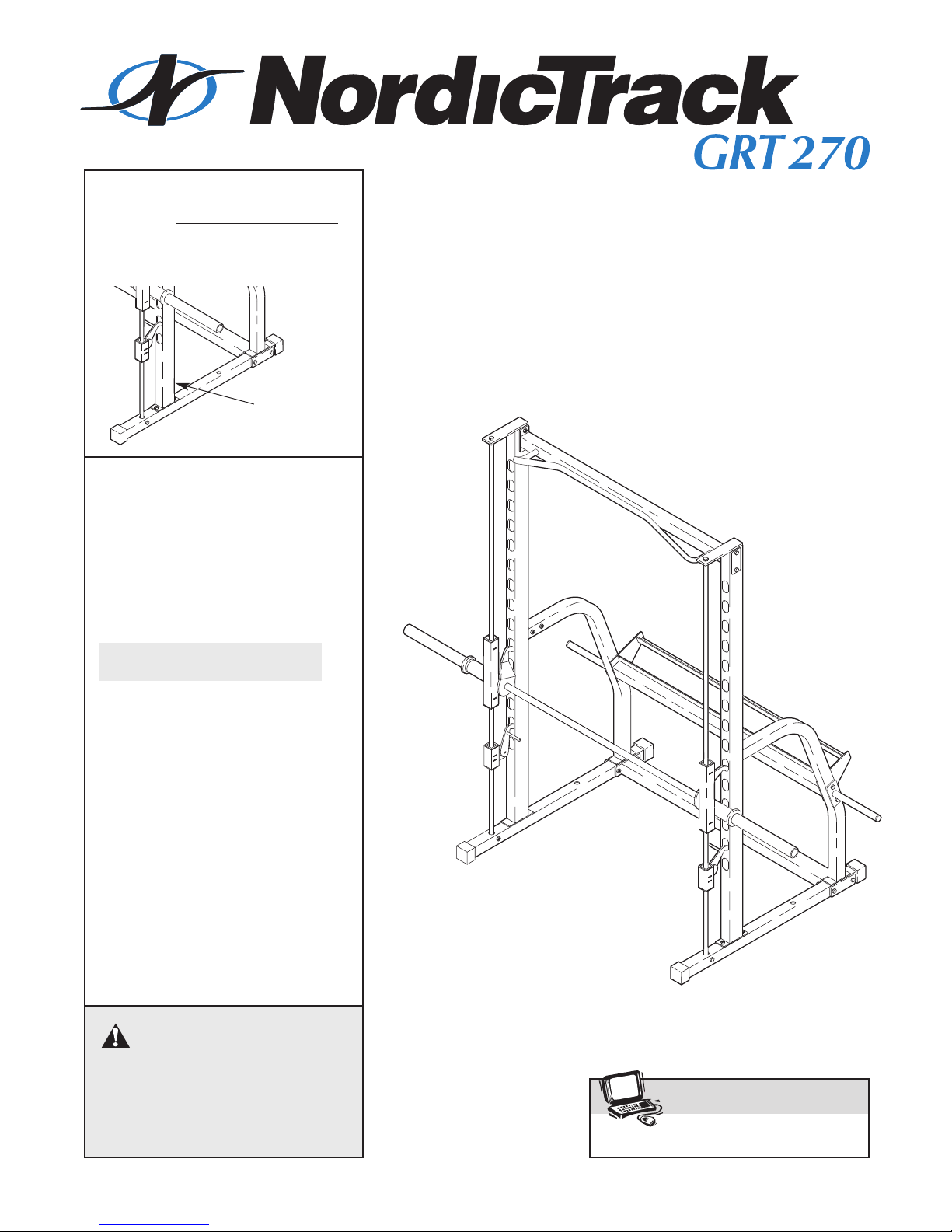
Model No. NTEVBE04911
www.iconeurope.com
Visit our website at
Serial No.
Write the serial number in the
space above for reference.
Serial
Number
Decal
QUESTIONS?
As a manufacturer, we are committed to providing complete
customer satisfaction. If you
have questions, or if there are
missing or damaged parts,
please call:
08457 089 009
USER’S MANUAL
Or write:
ICON Health & Fitness Ltd.
Unit 4
Revie Road Industrial Estate
Revie Road
Beeston
Leeds, LS1
UK
email: csuk@iconeurope.com
18JG
CAUTION
Read all precautions and instructions in this manual before
using this equipment. Save this
manual for future reference.
Page 2

Table of Contents
®
Important Precautions . . . . . . . . . . . . . . . . . . . . . . . . . . . . . . . . . . . . . . . . . . . . . . . . . . . . . . . . . . . . . . . . . . . . . . 3
Before You Begin . . . . . . . . . . . . . . . . . . . . . . . . . . . . . . . . . . . . . . . . . . . . . . . . . . . . . . . . . . . . . . . . . . . . . . . . . . 4
Part Identification Chart . . . . . . . . . . . . . . . . . . . . . . . . . . . . . . . . . . . . . . . . . . . . . . . . . . . . . . . . . . . . . . . . . . . . . 5
Assembly . . . . . . . . . . . . . . . . . . . . . . . . . . . . . . . . . . . . . . . . . . . . . . . . . . . . . . . . . . . . . . . . . . . . . . . . . . . . . . . . 6
Adjusting the Weight Rack . . . . . . . . . . . . . . . . . . . . . . . . . . . . . . . . . . . . . . . . . . . . . . . . . . . . . . . . . . . . . . . . . . 11
Exercise Guidelines . . . . . . . . . . . . . . . . . . . . . . . . . . . . . . . . . . . . . . . . . . . . . . . . . . . . . . . . . . . . . . . . . . . . . . .12
Muscle Chart . . . . . . . . . . . . . . . . . . . . . . . . . . . . . . . . . . . . . . . . . . . . . . . . . . . . . . . . . . . . . . . . . . . . . . . . . . . . .13
Ordering Replacement Parts . . . . . . . . . . . . . . . . . . . . . . . . . . . . . . . . . . . . . . . . . . . . . . . . . . . . . . . . .Back Cover
Note: A Part List/Exploded Drawing is attached in the centre of this manual. Remove the Part List/Exploded
Drawing before beginning assembly.
NordicTrack is a registered trademark of ICON Health & Fitness, Inc.
2
Page 3
Important Precautions
WARNING: To reduce the risk of serious injury, read the following important precau-
tions before using the weight rack.
1. Read all instructions in this manual before
using the weight rack. Use the weight rack
only as described in this manual.
2. It is the responsibility of the owner to ensure
that all users of the weight rack are adequately informed of all precautions.
3. The weight rack is intended for home use
only. Do not use the weight rack in a commercial, rental, or institutional setting.
4. Use the weight rack only on a level surface.
Cover the floor beneath the weight rack to
protect the floor or carpet.
5. Inspect and tighten all parts each time you
use the weight rack. Replace any worn parts
immediately.
6. Keep children under 12 and pets away from
the weight rack at all times.
7. Keep hands and feet away from moving
parts.
11. Always set both safety spotters at the same
height.
12. The weight rack is designed to support a
maximum of 254 kg (560 lbs.), including the
user, a barbell and weights (not included). Do
not place more than 141 kg (310 lbs.), including the barbell, on the weight gliders and
safety spotters.
13. If you feel pain or dizziness whilst exercising, stop immediately and begin cooling
down.
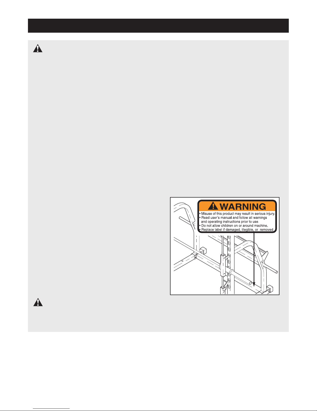
14. The decal shown below has been placed on
the weight rack in the indicated location. If
the decal is missing or illegible, please call
our Customer Service Department to order a
free replacement decal. Apply the decal in
the indicated location.
8. Always wear athletic shoes for foot protection whilst exercising.
9. Always make sure that there is an equal
amount of weight (not included) on each side
of the barbell.
10. Always secure your weights (not included)
with weight clips when they are mounted on
the barbell.
WARNING: Before beginning this or any exercise program, consult your physician. This
is especially important for persons over the age of 35 or persons with pre-existing health problems.
Read all instructions before using. ICON assumes no responsibility for personal injury or property
damage sustained by or through the use of this product.
3
Page 4
Before You Begin
Thank you for selecting the versatile NordicTrack
®
GRT 270 weight rack. Whether your goal is a shapely
figure, dramatic muscle size and strength, or a healthier cardiovascular system, the GRT 270 will help you
achieve the specific results you want. In addition, the
GRT270 can be used with the optional NordicTrack
®
GRT200 weight bench, shown in the drawing below.
To order the GRT200, call 08457 089 009.
For your benefit, read this manual carefully before
using the NordicTrack®GRT 270 weight rack. If you
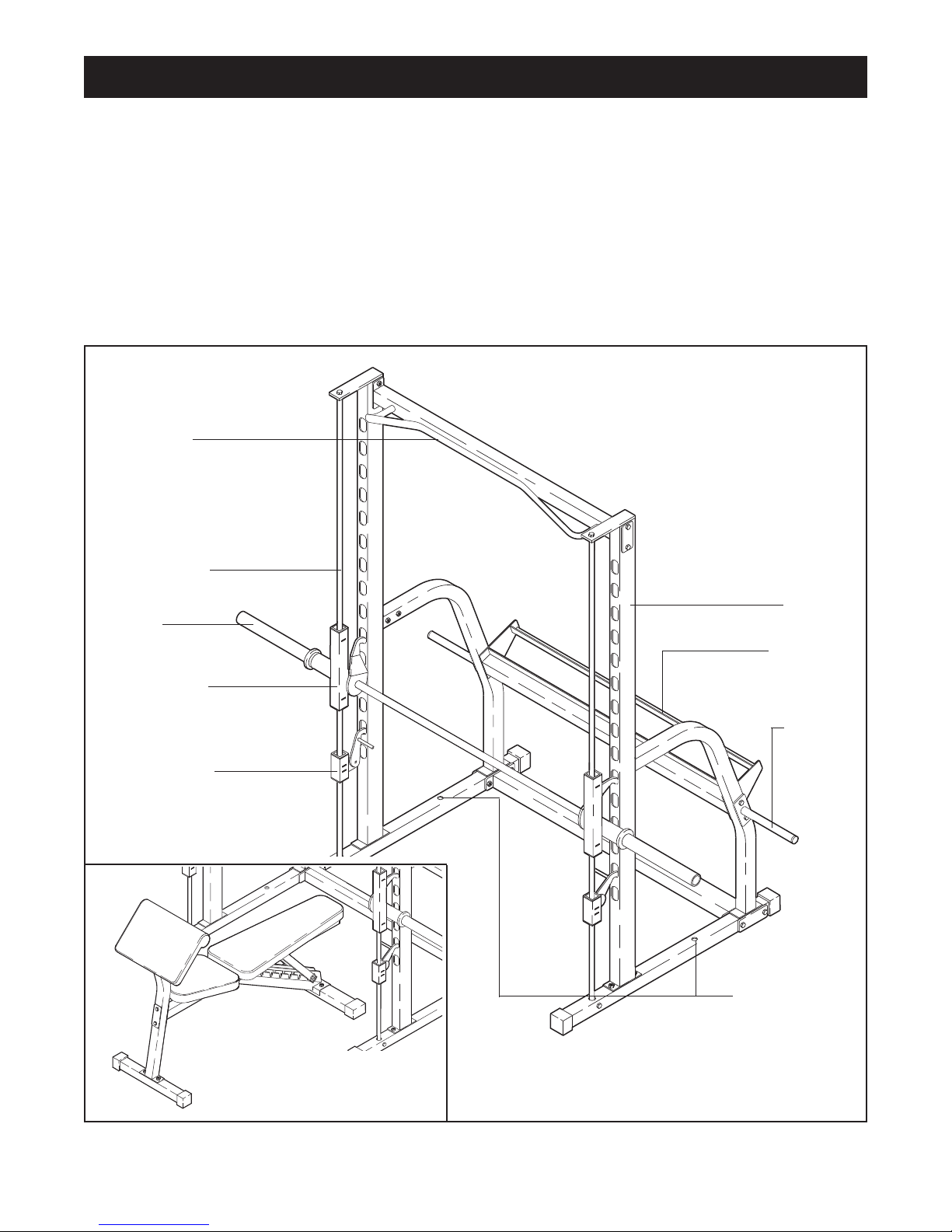
Pull-up Bar
RIGHT SIDE
Weight Guide
have additional questions, please call our Customer
Service Department at 08457 089 009. To help us
assist you, please mention the product model number
and serial number when calling. The model number is
NTEVBE04911. The serial number can be found on a
decal attached to the weight rack (see the front cover
of this manual).
Before reading further, please familiarize yourself with
the parts that are labeled in the drawing below.
Note: The terms “right side” and “left side”
are determined relative to a person sitting on
the optional weight bench; they do not refer to
right and left on the drawings in this manual.
LEFT SIDE
Barbell
Weight Glider
Safety Spotter
Upright
Dumbbell
Storage
Rack
Weight
Storage
Tube
Anchor Holes*
Optional NordicT
Model No. NTEVBE01410
rack
®
GR
T200
*Note: Use the anchor holes to secure the
weight bench to a fixed position, if desired.
4
Page 5
Part Identification Chart
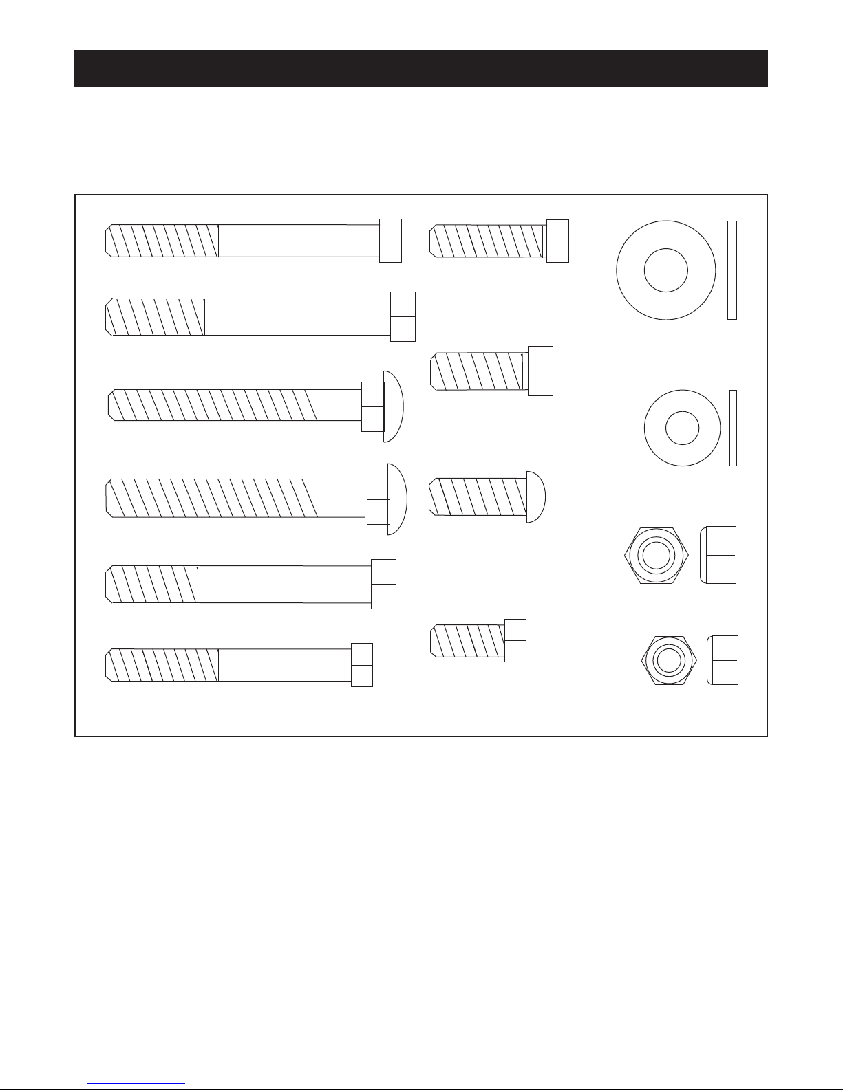
M8 x 63mm Bolt (23)
M8 x 30mm Bolt (22)
M8 x 70mm Bolt (25)
M10 x 67mm Carriage Bolt (24)
M10 x 25mm Bolt (36)
M8 Washer (35)
M10 Nylon Locknut (7)
M8 Nylon Locknut (37)
M8 x 20mm
Screw (33)
M10 x 25mm Button
Head Bolt (27)
M8 x 65mm Carriage Bolt (38)
M10 Washer (3)
M10 x 73mm Bolt (29)
M10 x 68mm Bolt (26)
This chart is provided to help you identify the small parts used in assembly. The number in parenthesis below
each part refers to the key number of the part from the Part List is the centre of this manuel. Important: Some
parts may have been pre-assembled for shipping purposes. If you cannot find a part in the parts bags,
check to see if it has been pre-assembled.
5
Page 6
Assembly
Make Things Easier for Yourself
Everything in this manual is designed to ensure
that the weight rack can be assembled successfully by anyone. However, it is important to
recognise that the weight rack has many parts
and that the assembly process will take time.
Most people find that by setting aside plenty of
time, and by deciding to make the task enjoyable, assembly will go smoothly.
• Assembly requires two people.
• As you assemble the weight rack, make sure all
parts are oriented as shown in the drawings.
• For help identifying the small parts, use the Part
Identification Chart on page 5.
ighten all parts as you assemble them, unless
• T
instructed to do otherwise.
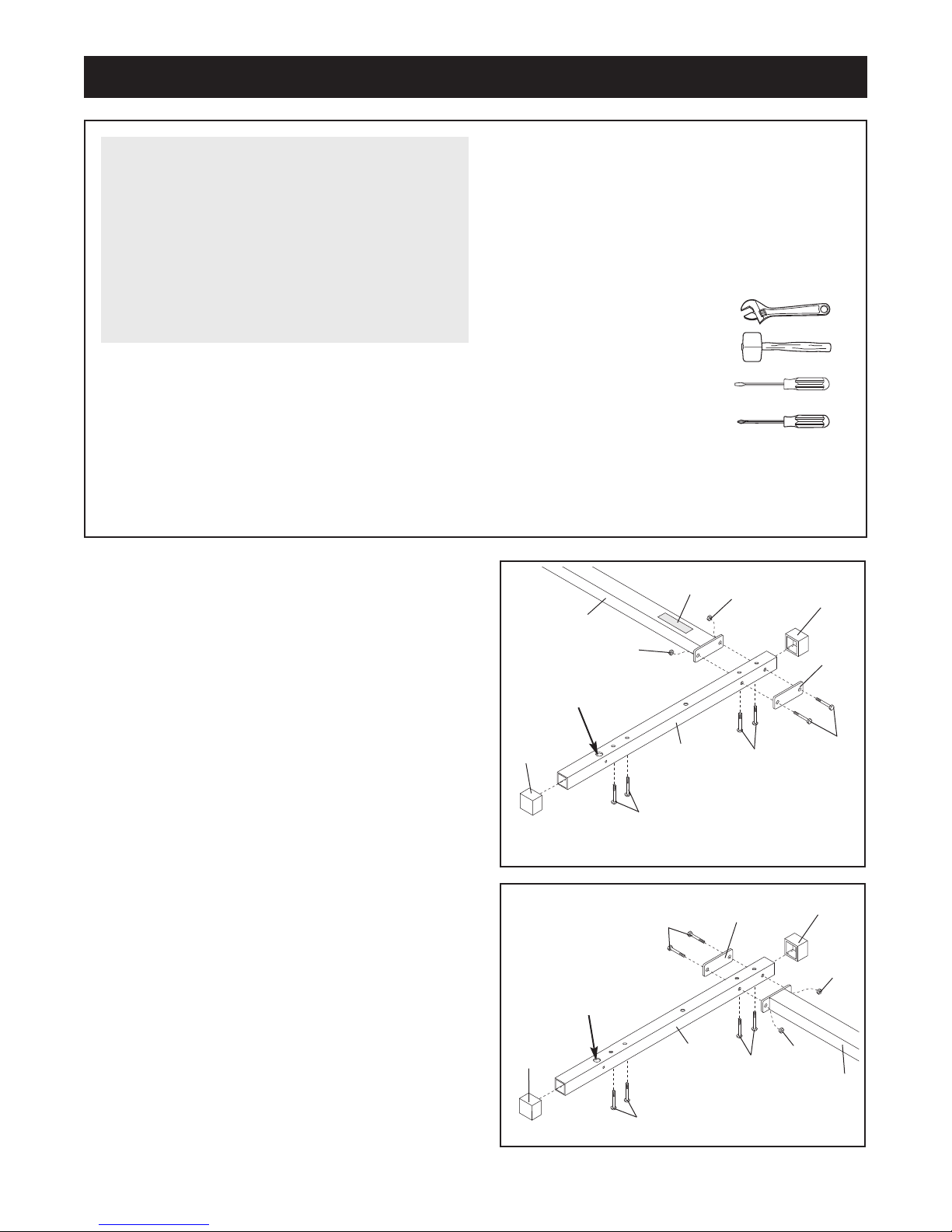
The following tools (not included) are required
for assembly:
• Two adjustable spanners
• One rubber mallet
• One standard screwdriver
• One phillips screwdriver
• Place all parts in a cleared area and remove the
packing materials. Do not dispose of the packing
materials until assembly is completed.
1. Before beginning, make sure that you understand
the information in the box above.
Press a 50mm Square Outer Cap (10) onto each end
of a Base (4). Turn the Base so the large hole is in
the position shown. Insert two M8 x 65mm Carriage
Bolts (38) and two M10 x 67mm Carriage Bolts (24)
up into the indicated holes in the Base. Place the
Base flat on the floor.
Turn the Base Crossbar (12) so the warning decal is
on top.
two M8 x 70mm Bolts (25), a Large Support Plate (8),
and two M8 Nylon Locknuts (37).
Nylon Locknuts yet.
2. Press a 50mm Square Outer Cap (10) onto each end
of the other Base (4).
is in the position shown. Insert two M8 x 65mm
Carriage Bolts (38) and two M10 x 67mm Carriage
Bolts (24) up into the indicated holes in the Base.
Place the Base flat on the floor.
Attach the Base (4) to the Base Crossbar (12) with
two M8 x 70mm Bolts (25), a Large Support Plate (8),
and two M8 Nylon Locknuts (37).
Nylon Locknuts yet.
Attach the Base (4) to the Base Crossbar with
Do not tighten the
urn the Base so the large hole
T
Do not tighten the
Assembly will be more convenient if you have the
following tools: A socket set, a set of open-end or
closed-end spanners, or a set of ratchet spanners.
1
12
37
Large Hole
10
2
Large Hole
10
24
25
Decal
4
4
37
8
38
10
8
38
10
37
25
37
12
24
6
Page 7

3. Slide a Brace (2) onto the bracket on one of the
Uprights (1). Attach the Brace to the Upright with two
M10 x 68mm Bolts (26), four M10 Washers (3), and
two M10 Nylon Locknuts (7).
Nylon Locknuts yet.
Slide the Upright (1) and the Brace (2) onto the M10
x 67mm Carriage Bolts (24) and the M8 x 65mm
Carriage Bolts (38) in the left Base (4). Attach the
Upright with two M10 Nylon Locknuts (7). Attach the
Brace with two M8 Washers (35) and two M8 Nylon
Locknuts (37). Do not tighten the Nylon Locknuts
yet.
Do not tighten the
3
1
7
3
2
3
26
4. Slide the other Brace (2) onto the bracket on the
other Upright (1). Attach the Brace to the Upright with
two M10 x 68mm Bolts (26), four M10 Washers (3),
and two M10 Nylon Locknuts (7). Do not tighten the
Nylon Locknuts yet.
Slide the Upright (1) and the Brace (2) onto the M10
x 67mm Carriage Bolts (24) and the M8 x 65mm
Carriage Bolts (38) in the right Base (4).
Upright with two M10 Nylon Locknuts (7). Attach the
Brace with two M8 Washers (35) and two M8 Nylon
Locknuts (37). Do not tighten the Nylon Locknuts
yet.
Attach the
Bracket
7
4
24
4
1
26
3
2
37
35
38
7
3
Bracket
38
7
4
24
37
35
7
Page 8

5. Press a 25mm Round Cap (34) into the end of a
Weight Storage Tube (13).
Whilst a second person holds the Middle Crossbar (5)
in the position shown, attach the W
Tube (13) and the Middle Crossbar to the left Brace
(2) with two M10 x 73mm Bolts (29) and two M10
Nylon Locknuts (7). Do not tighten the Nylon
Locknuts yet.
eight Storage
5
2
5
13
29
7
6. Press a 25mm Round Cap (34) into the end of the
other Weight Storage Tube (13).
Whilst a second person holds the Middle Crossbar
(5), attach the Weight Storage Tube (13) and the
Middle Crossbar to the right Brace (2) with two M10 x
73mm Bolts (29) and two M10 Nylon Locknuts (7).
Do not tighten the Nylon Locknuts yet.
7. Have a second person hold the Top Crossbar (6)
between the Uprights (1). Make sure that the pull-up
bar is on the side shown.
Attach the Top Crossbar (6) to the Uprights (1) with
four M10 x 73mm Bolts (29), two Small Support
Plates (9), and four M10 Nylon Locknuts (7). Do not
tighten the Nylon Locknuts yet.
6
7
29
29
29
34
29
9
2
7
29
13
5
7
7
6
7
Pull-up
Bar
7
34
9
29
1
1
29
8
Page 9

8. Press a 25mm Bushing (31) into each end of the
Locking Bar (20).
Insert the Barbell (21) through the Locking Bar (20)
until the Barbell is centred in the Locking Bar
.
8
31
20
21
31
9. Identify the Left Weight Glider (18) by looking at the
position of the round tube.
Press a 38mm Bushing (16) into each end of the
round tube on the Left Weight Glider (18).
Slide the Left Weight Glider (18) onto the left end of
the Barbell (21).
is turned as shown in the drawing. Secure the
Weight Glider to the Barbell with a hand-tightened M8
x 20mm Screw (33).
Attach the Right Weight Glider (not shown) to the
right end of the Barbell (21) in the same manner.
10. Identify the left Safety Spotter (14) by the position of
the handle on the Left Spotter Hook (42). Place the
left Safety Spotter on the left Base (4) so it is centred
over the indicated hole.
Have a second person hold the Locking Bar (20) so
that the Left W
Safety Spotter (14). Insert a Weight Guide (11) into
the Left Weight Glider, the left Safety Spotter, and the
hole in the Base (4).
away from the Upright (1) as you insert it.
Make sure that the Weight Glider
eight Glider (18) rests on top of the left
Note: T
ilt the Weight Guide
9
10
16
21
4
11
20
18
18
33
16
Round tube
1
Attach the Weight Guide (11) to the Base (4) with an
M8 x 63mm Bolt (23), two M8 Washers (35), and an
M8 Nylon Locknut (37). Do not tighten the Nylon
Locknut yet.
Attach the right Safety Spotter (not shown) and the
Right Weight Glider (not shown) to the right Base (4)
in the same manner
.
Handle
14
37
35
42
4
Hole
23
9
Page 10

11. Note: If you are not planning to use Olympic
weights with the weight rack, centre the Barbell
(21), and tighten the M8 x 20mm Screws (33) used
in step 9. Then proceed to step 12. Keep the two
Weight Adapters (19) in a safe place in case you
need them in the future.
Fully engage the indicated hook on both sides of
the weight rack before beginning this step.
11
Insert a 48mm Bushing (30) into the end of a Weight
Adapter (19). With a second person holding the
Barbell (21) so that it cannot turn, use the hex key to
secure the Weight Adapter to the Barbell with a Large
Washer (28) and an M10 x 25mm Button Head Bolt
(27).
Note: The Large Washer must fit into the
indentation in the 48mm Bushing in the Weight
Adapter.
Pull the remaining length of the Barbell (21) in the
direction shown. Next, tighten the M8 x 20mm
Screws (33) used in step 9. Attach the other Weight
Adapter (19) to the other end of the Barbell (21) in the
same manner.
12. Attach the upper end of one of the Weight Guides
(11) to the bracket on the Upright (1) with an M8 x
30mm Bolt (22) and an M8 Washer (35).
Attach the other Weight Guide (not shown) to the
other Upright (not shown) in the same manner.
Tighten all of the nylon locknuts used in steps 1
to 10.
12
Hook
21
35
22
19
30
28
27
13. Make sure that all parts are properly tightened
before you use the weight rack. The use of all
remaining parts will be explained in Adjusting the
Weight Rack starting on the following page.
11
1
10
Page 11

Adjusting the Weight Rack
This section explains how the weight rack is adjusted. See the Exercise Guidelines on page 12 for important
information on how to get the most benefit from your exercise program. Also, refer to the accompanying exercise
to see the correct form for each exercise.
guide
Inspect and tighten all parts each time you use the weight rack. Replace any worn parts immediately. The weight
rack can be cleaned with a damp cloth and a mild, non-abrasive detergent. Do not use solvents.
USING THE LOCKING BAR AND SAFETY SPOTTERS
Before starting an exercise, position the Barbell (21) and
the Safety Spotters (14) in the correct position for that
exercise.
To do this, stand in front of the cage and grip the Locking
Bar (20) with both hands. Turn the Locking Bar until the
two hooks disengage the slots in the Uprights (1). Move
the Locking Bar to a new position and turn the Locking
Bar until the hooks engage the slots in the Uprights.
Note: Always start an exercise with the Barbell (21)
positioned at the lowest point to which it will move
during the exercise.
Position both Safety Spotters (14) directly under the
Weight Gliders (17, 18).
USING THE SAFETY SPOTTERS
To move a Safety Spotter (14) to a new position, grip the
handle on one side of the Spotter Hook (41, 42 [not
shown]) and pull the Spotter Hook out of the slot in the
Upright (1). Raise or lower the Safety Spotter to a new
position and turn the Spotter Hook until it engages one of
the slots in the Upright.
17
14
1
1
20
21
18
14
1
WARNING: Always set both Safety
Spotters (14) at the same height.
ATTACHING WEIGHTS TO THE BARBELL
To use the Barbell (21), slide the desired amount of
weight (not included) onto each end of the Barbell.
Secure the weights with the Large Weight Clips (39).
Note: To use standard weights, the Weight Adapters (19)
should be removed from the Barbell. Attach weights to
the Barbell with the Small Weight Clips (not shown).
WARNING: Do not place more than
18 kg (260 lbs.) on the Barbell (21).
1
the weights with W
are on the Barbell. Always place the same amount
of weight on each side of the Barbell.
eight Clips (39, 40) when they
14
41
Handle
19
21
39
Always secure
11
Page 12

Exercise Guidelines
THE FOUR BASIC TYPES OF WORKOUTS
Muscle Building
To increase the size and strength of your muscles,
push them close to their maximum capacity. Your
muscles will continually adapt and grow as you progressively increase the intensity of your exercise. You
can adjust the intensity level of an individual exercise
in two ways:
• by changing the amount of weight used
• by changing the number of repetitions or sets per-
formed. (A “repetition” is one complete cycle of an
exercise, such as one sit-up. A “set” is a series of
repetitions.)
The proper amount of weight for each exercise
depends upon the individual user. You must gauge
your limits and select the amount of weight that is
right for you. Begin with 3 sets of 8 repetitions for
each exercise you perform. Rest for 3 minutes after
each set. When you can complete 3 sets of 12 repetitions without difficulty, increase the amount of weight.
Toning
You can tone your muscles by pushing them to a
moderate percentage of their capacity. Select a moderate amount of weight and increase the number of
repetitions in each set. Complete as many sets of 15
to 20 repetitions as possible without discomfort. Rest
for 1 minute after each set. Work your muscles by
completing more sets rather than by using high
amounts of weight.
Weight Loss
To lose weight, use a low amount of weight and
increase the number of repetitions in each set.
Exercise for 20 to 30 minutes, resting for a maximum
of 30 seconds between sets.
Cross T
Cross training is an ef
and well-balanced fitness program. An example of a
balanced program is:
Plan weight training workouts on Monday
•
Wednesday, and Friday.
• Plan 20 to 30 minutes of aerobic exercise, such as
cycling or swimming, on
Rest from both weight training and aerobic exercise
•
for at least one full day each week to give your body
time to regenerate.
The combination of weight training and aerobic exercise will reshape and strengthen your body, plus
develop your heart and lungs.
raining
ficient way to get a complete
,
uesday and Thursday.
T
PERSONALISING YOUR EXERCISE PROGRAM
Determining the exact length of time for each workout,
as well as the number of repetitions or sets completed, is an individual matter. It is important to avoid
overdoing it during the first few months of your exercise program. You should progress at your own pace
and be sensitive to your body’s signals. If you experience pain or dizziness at any time whilst exercising,
stop immediately and begin cooling down. Find out
what is wrong before continuing. Remember that adequate rest and a proper diet are important factors in
any exercise program.
WARMING UP
Begin each workout with 5 to 10 minutes of stretching
and light exercise to warm up. Warming up prepares
your body for more strenuous exercise by increasing
circulation, raising your body temperature and delivering more oxygen to your muscles.
WORKING OUT
Each workout should include 6 to 10 different exercises. Select exercises for every major muscle group,
emphasising areas that you want to develop most. To
give balance and variety to your workouts, vary the
exercises from session to session.
Schedule your workouts for the time of day when your
energy level is the highest. Each workout should be
followed by at least one day of rest. Once you find the
schedule that is right for you, stick with it.
EXERCISE FORM
Maintaining proper form is an essential part of an
effective exercise program. This requires moving
through the full range of motion for each exercise,
and moving only the appropriate parts of the body
Exercising in an uncontrolled manner will leave you
feeling exhausted. On the exercise guide accompany
ing this manual you will find photographs showing the
correct form for several exercises, and a list of the
muscles affected. Refer to the muscle chart on the
next page to find the names of the muscles.
The repetitions in each set should be performed
smoothly and without pausing. The exertion stage of
each repetition should last about half as long as the
return stage. Proper breathing is important. Exhale
during the exertion stage of each repetition and inhale
during the return stroke. Never hold your breath.
.
-
12
Page 13

Rest for a short period of time after each set. The
O
P
Q
R
S
T
V
X
W
N
M
J
G
F
H
I
K
E
C
D
B
A
L
U
ideal resting periods are:
Rest for three minutes after each set for a muscle
•
building workout.
Rest for one minute after each set for a toning work-
•
out.
• Rest for 30 seconds after each set for a weight loss
workout.
Plan to spend the first couple of weeks familiarising
yourself with the equipment and learning the proper
form for each exercise.
COOLING DOWN
End each workout with 5 to 10 minutes of stretching.
Include stretches for both your arms and legs. Move
Muscle Chart
A. Sternomastoid (neck)
B. Pectoralis Major (chest)
C. Biceps (front of arm)
D. Obliques (waist)
E. Brachioradials (forearm)
F. Hip Flexors (upper thigh)
G. Abductor (outer thigh)
H. Quadriceps (front of thigh)
I. Sartorius (front of thigh)
J. Tibialis Anterior (front of calf)
K. Soleus (front of calf)
L. Anterior Deltoid (shoulder)
M. Rectus Abdominus (stomach)
N. Adductor (inner thigh)
rapezius (upper back)
T
O.
P. Rhomboideus (upper back)
Posterior Deltoid (shoulder)
Q.
R. Triceps (back of arm)
S. Latissimus Dorsi (mid back)
T. Spinae Erectors (lower back)
U. Gluteus Medius (hip)
V. Gluteus Maximus (buttocks)
. Hamstring (back of leg)
W
Gastrocnemius (back of calf)
X.
slowly as you stretch and do not bounce. Ease into
each stretch gradually and go only as far as you can
without strain. Stretching at the end of each workout
is an effective way to increase flexibility.
STAYING MOTIVATED
For motivation, keep a record of each workout. The
chart on page 23 of this manual can be photocopied
and used to schedule and record your workouts. List
the date, the exercises performed, the weight used,
and the numbers of sets and repetitions completed.
Record your weight and key body measurements at
the end of every month. Remember, the key to
achieving the greatest results is to make exercise a
regular and enjoyable part of your everyday life.
13
Page 14

MONDAY
Date:
/ /
EXERCISE WEIGHT SETS REPS
TUESDAY
Date:
/ /
WEDNESDAY
Date:
/ /
THURSDAY
Date:
/ /
AEROBIC EXERCISE
EXERCISE WEIGHT SETS REPS
AEROBIC EXERCISE
FRIDAY
Date:
EXERCISE WEIGHT SETS REPS
/ /
Make photocopies of this page for scheduling and recording your workouts.
14
Page 15

MONDAY
Date:
/ /
EXERCISE WEIGHT SETS REPS
TUESDAY
Date:
/ /
WEDNESDAY
Date:
/ /
THURSDAY
Date:
/ /
AEROBIC EXERCISE
EXERCISE WEIGHT SETS REPS
AEROBIC EXERCISE
FRIDAY
Date:
EXERCISE WEIGHT SETS REPS
/ /
Make photocopies of this page for scheduling and recording your workouts.
15
Page 16

Ordering Replacement Parts
If you encounter any difficulties with this product, or if you need to order replacement parts, call the ICON Health
& Fitness Ltd. office, or write:
ICON Health & Fitness Ltd.
Unit 4
Revie Road Industrial Estate
Revie Road
Beeston
Leeds, LS118JG
UK
Tel:
08457 089 009
Outside the UK: 0 (444) 113 387 7133
Fax: 0 (444) 113 387 7125
When ordering parts, please be prepared to give the following information:
• The MODEL NUMBER OF THE PRODUCT (NTEVBE04911)
®
• The NAME OF THE PRODUCT (NordicTrack
• The SERIAL NUMBER OF THE PRODUCT (see the front cover of this manual)
• The KEY NUMBER AND DESCRIPTION OF THE PART(S) (see the Part List and the Exploded Drawing at the
centre of the manual)
GRT 270 weight rack)
Part No. 197137 R0803A
Printed in China
2003 ICON Health & Fitness, Inc.
©
Page 17

REMOVE THIS PART LIST/EXPLODED DRAWING
81
FROM THE MANUAL
SAVE THIS PART LIST/EXPLODED DRAWING AND THE USER’S MANUAL
FOR FUTURE REFERENCE
Page 18

Part List—Model No. NTEVBE04911
Key No. Qty. Description Key No. Qty. Description
R0803A
1 2 Upright
2 2 Brace
3 8 M10 Washer
4 2 Base
5 1 Middle Crossbar
6 1 Top Crossbar
7 18 M10 Nylon Locknut
8 2 Large Support Plate
9 2 Small Support Plate
10 4 50mm Square Outer Cap
11 2 Weight Guide
12 1 Base Crossbar
13 2 Weight Storage Tube
14 2 Safety Spotter
15 0 Not Used
16 4 38mm Bushing
17 1 Right Weight Glider
18 1 Left Weight Glider
19 2 Weight Adapter
20 1 Locking Bar
21 1 Barbell
22 2 M8 x 30mm Bolt
23 2 M8 x 63mm Bolt
Note: “#” indicates a non-illustrated part. Specifications are subject to change without notice. See the back cover
of the user’s manual for information about ordering replacement parts.
24 4 M10 x 67mm Carriage Bolt
25 4 M8 x 70mm Bolt
26 4 M10 x 68mm Bolt
27 2 M10 x 25mm Button Head Bolt
28 2 Large Washer
29 8 M10 x 73mm Bolt
30 2 48mm Bushing
31 2 25mm Bushing
32 8 45mm x 45mm Bushing
33 2 M8 x 20mm Screw
34 2 25mm Round Cap
35 10 M8 Washer
36 2 M10 x 25mm Bolt
37 10 M8 Nylon Locknut
38 4 M8 x 65mm Carriage Bolt
39 2 Large Weight Clip
40 2 Small Weight Clip
41 1 Right Spotter Hook
42 1 Left Spotter Hook
# 1 User’s Manual
# 1 Exercise Guide
# 1 Hex Key
Page 19

21
28
27
19
20
10
23
11
25
7
24
37
38
16
16
16
19
28
27
17
14
14
18
33
33
37
24
10
37
4
23
38
25
8
10
7
37
29
13
26
7
2
1
11
9
29
22
7
7
37
10
37
8
12
5
7
7
6
7
7
2
26
29
29
13
1
22
9
29
34
34
32
32
30
30
31
31
32
32
32
32
32
7
36
7
36
32
35
35
4
35
3
3
35
3
3
35
35
40
39
41
42
35
35
Exploded Drawing—Model No. NTEVBE04911
R0803A
 Loading...