


APPLICANT: Lucent Technologies |
FCC ID: AS5RWM232V200WAUS |
EXHIBIT 3
Installation and Operating Instructions
SECTION 2.1033 (a) (3)

|
|
1 |
|
Introducing the WaveACCESS |
|||
|
|||
NET 2400 System |
|
||
THIS IS AN INCOMPLETE DRAFT.
This chapter introduces the WaveACCESS NET product family, including its main features and benefits. In addition, workflows for installing the CU232 and the remote unit are provided.
About this chapter:
Introducing the WaveACCESS NET Product Family, page 1-2, provides an overview of the WaveACCESS NET product family.
Features and Benefits, page 1-6, describes the numerous features and benefits that can enhance working environments using wireless systems.
WaveACCESS NET Ruggedized Unit, page 1-7, describes the additional features and benefits provided by the ruggedized WaveACCESS NET 2400 units, for outdoor installation.
Technical Specifications, page 1-8, describes the technical specifications of the WaveACCESS NET units.
CU232 Installation Workflow, page 1-11, provides a workflow for installing the WaveACCESS NET CU232.
Remote Unit Installation Workflow, page 1-12, provides a workflow for installing the WaveACCESS NET MDR232 and
SDR232.
WaveACCESS NET 2400 Installation Guide |
1-1 |

Introducing the WaveACCESS NET 2400
System
Introducing the WaveACCESS NET Product
Family
The WaveACCESS NET system is a radio-based, high-capacity, high bit rate, low-cost packet switched wireless system that operates in the 2.4 Ghz ISM unlicensed band to provide point-to-multipoint wireless Internet access. It is designed to provide communications for several hundred users simultaneously accessing the Internet or intranet.
WaveACCESS NET employs Frequency Hopping SpreadSpectrum (FHSS) technology at data rates of 3.2 and 1.6 Mbps. The fully digital FHSS radio provides protection against interference and enables operation of collocated systems, thereby increasing overall data throughput. WaveACCESS NET has been optimized for IP traffic and provides high-speed networking at distances of several miles.
The WaveACCESS NET system consists of a central site known as the base station, and up to several hundred remote sites. The base station is where the system links to a backbone, for example, telephony, satellite, wireless, or digital cable data transmissions. The WaveACCESS NET CU232 sits at the base station.
The remote sites are the user locations, where remote WaveACCESS NET xDR232 units act as LAN adapters.
1-2 |
WaveACCESS NET 2400 Installation Guide |
Introducing the WaveACCESS NET 2400
System
The WaveACCESS NET system is comprised of the following:
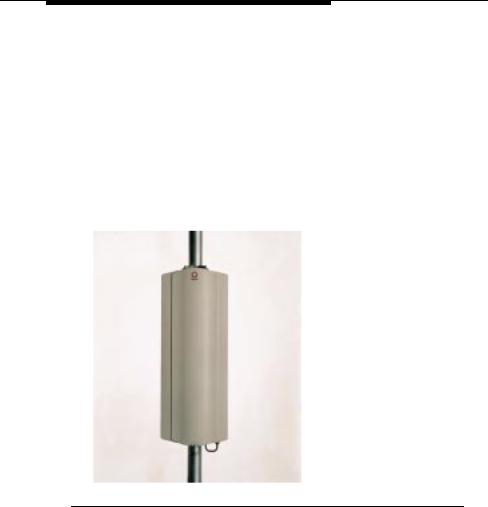
■WaveACCESS NET CU232: A wireless point-to-multipoint central unit that can support up to 60 remote units at a data rate of 3.2 Mbps each. Using unique RFStacker™ technology, up to ten WaveACCESS NET CU232 units can be collocated in a single site, creating a cell of up to 600 remote units at a data rate of up to 25 Mbps. A remote unit does not necessarily indicate a single user (for example, an MDR232 can support an entire LAN). Therefore, the actual number of users the WaveACCESS NET CU232 is able to support is considerably higher than the number of remote units.
Figure 1-1 WaveACCESS NET CU232
WaveACCESS NET 2400 Installation Guide |
1-3 |
Introducing the WaveACCESS NET 2400
System
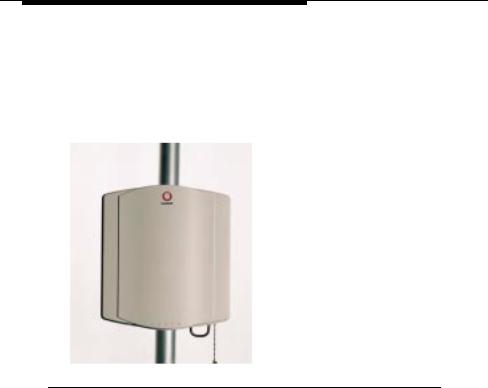
■WaveACCESS NET SDR232: A standalone wireless LAN adapter (remote unit), including a built-in antenna, designed to connect to any computer’s Ethernet adapter card and allow fast linking of any workstation to the Internet or Intranet. This allows the user access to the full bandwidth, without having to share the capacity with multiple users on a network.
Figure 1-2 WaveACCESS NET xDR232
■WaveACCESS NET MDR232: A multidrop remote unit, including a built-in antenna, that provides a bridging function and enables a complete LAN to be connected over a wireless network. This unit has particular application for a small office environment, in which a single MDR232 would enable all the computers to access the Internet.
1-4 |
WaveACCESS NET 2400 Installation Guide |
Introducing the WaveACCESS NET 2400
System
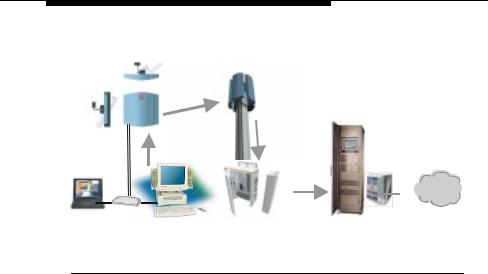
A high-level view of the system architecture is shown in Figure 1-3.
Air Interface
Frame Relay
T1/E1

 Internet
Customer Premises |
|
Base Station |
|
Switching Center |
Figure 1-3 High Level System Architecture
Sectorization of the Central Site
WaveACCESS NET CU232 units are typically installed in business or residential areas which do not have well-defined boundaries. It is not always possible to place the base station, with the central units and antennas, in the optimal location. Therefore, the WaveACCESS NET system provides the ability to sectorize the base station by using multiple CU232 units, each of which covers a sector of the total area to be covered.
This allows an increase in cell range from approximately two miles, for an omnidirectional 8dBi antenna, to approximately seven miles for a 20dBi panel antenna.
If you have many users in one area, you may have more than one CU232 covering the same area to provide optimal throughput for all the users.
WaveACCESS NET 2400 Installation Guide |
1-5 |

Introducing the WaveACCESS NET 2400
System
Features and Benefits
The WaveACCESS NET wireless point-to-multipoint system has numerous features and benefits that can enhance working environments where wireless systems are essential:
■Simple deployment, installation and operation.
■Digital Frequency Hopping Spread Spectrum (FHSS) technology that can support many overlapping links and deliver resilience to interference and exceptional data integrity.
■Operates in the 2.4 GHz ISM band, making it available for unlicensed use in most parts of the world.
■No configuration requirements, just plug it in and it works.
■Management and configuration utilities enable you to quickly make advanced configuration changes.
■Fully digital packet radio with advanced QPSK and 16QAM modulation.
■Advanced bandwidth-enhancing ADEQ™ technology.
■Optional dual antenna diversity.
■SNMP managed, MIB II compliant with proprietary MIB.
■Long range, high speed point-to-multipoint links.
■Bandwidth management on a per-link basis.
■Improved security features for ISPs.
1-6 |
WaveACCESS NET 2400 Installation Guide |

Introducing the WaveACCESS NET 2400
System
WaveACCESS NET Ruggedized Unit
The WaveACCESS NET 2400 units are fully ruggedized and suitable for outdoor installation, in weather conditions of -40°C to 55°C.
An internal antenna is embedded in each unit, although there is also an option to use an external antenna for wider coverage. A single flexible cable is used to transmit data and supply the unit’s power. The WaveACCESS NET 2400 product now includes a power/data adapter that connects to the AC power supply directly and provides an Ethernet connection.
While the WaveACCESS NET 2400 system is fully compatible with the previous WaveACCESS NET version, it provides enhanced functionality, as follows:
■Firstly, the fact that the unit is ruggedized and has an embedded antenna precludes the need for a long RF cable connecting the indoor unit to its external antenna (with its inevitable losses). Thus, the signal quality and the effective ranges are improved.
Increased maximum range enables ISPs to accommodate more users with a higher data rate in that cell and at the same level of service. This benefits both ISPs and users of the system, as users with a low data rate use more bandwidth when transmitting the same data, than users with a higher data rate.
■Secondly, the WaveACCESS NET 2400 units custom cable connects to both the AC power supply and the Ethernet via a single box, as opposed to the two boxes (one each for power supply and Ethernet) in the previous version. The cable itself is thin and easy to manipulate and enables the unit to be placed up to 100 meters from the power supply.
■Thirdly, the WaveACCESS NET 2400 is easier to install.
WaveACCESS NET 2400 Installation Guide |
1-7 |

Introducing the WaveACCESS NET 2400
System
You have the option to set up an external antenna for wider coverage than is provided by the internal directional antenna. When an external antenna is used, it is connected directly to the radio output.
Technical Specifications
The following technical specifications for the WaveACCESS NET units are for reference purposes only. The actual product’s performance and compliance with local regulations may vary from country to country. Lucent Technologies reserves the right to improve the products from time to time and actual specifications may vary.
Table 1-1 Technical Specifications of the WaveACCESS NET Unit
MODELS: WaveACCESS NET CU232, MDR232, and SDR232
Description |
CU232 |
MDR232 AND SDR232 |
|
2.4 GHz Wireless |
2.4 GHz Wireless |
|
point-to-multipoint |
point-to-mulitpoint |
|
Ethernet Bridge |
Ethernet Bridge |
|
Central Unit |
|
|
|
|
Wireless |
Frequency Hopping Spread Spectrum (FHSS) |
|
Medium |
|
|
|
|
|
Operating |
2.402 - 2.480 GHz |
|
Frequency |
|
|
|
|
|
1-8 |
WaveACCESS NET 2400 Installation Guide |

Introducing the WaveACCESS NET 2400
System
Table 1-2 WaveACCESS NET Unit Performance Specifications
PERFORMANCE
Data Rate |
CU232 |
MDR232 AND SDR232 |
|
|
3.2 Mbps, fallback |
3.2 Mbps, fallback to 1.6 |
|
|
to 1.6 Mbps |
Mbps |
|
|
|
|
|
No. of Ind. |
79 |
|
|
Channels |
|
|
|
|
|
|
|
Cell |
CU232 |
MDR232 AND SDR232 |
|
Throughput |
Up to 2.2 Mbps @ |
Up to 2.2 Mbps @ 3.2 Mbps |
|
3.2 Mbps |
1.2 Mbps @ 1.6 Mpbs |
||
|
|||
|
1.2 Mbps @ |
|
|
|
1.6 Mbps |
|
|
|
|
|
|
Throughput |
ADEQ™ Adaptive Equalization |
||
Enhancement |
|
|
|
|
|
|
|
TECHNICAL DATA |
|
|
|
|
|
|
|
Radio |
FHSS using QPSK and QAM modulation |
||
Technology |
|
|
|
|
|
||
Antenna |
Reversed polarity SMA |
||
Connector |
|
|
|
|
|
||
Antenna |
Option for 2 separate antennas |
||
Diversity |
|
|
|
|
|
|
|
Output Power |
50 mW |
|
|
|
|
|
|
Wired LAN |
10Base-T (RJ-45) |
|
|
Connections |
|
|
|
|
|
||
Wired LAN |
IEEE 802.3 CSMA / CD |
||
Protocol |
|
|
|
|
|
|
|
WaveACCESS NET 2400 Installation Guide |
1-9 |
Introducing the WaveACCESS NET 2400
System
Table 1-3 WaveACCESS NET Unit Configuration and
Management Specifications
CONFIGURATION AND MANAGEMENT
Configuration |
Via any wired Ethernet LAN station, SNMP, |
|
|
TFTP, Bootp, or via RS-232 9-pin female |
|
|
D-type connector. |
|
|
|
|
SNMP |
MIB II, Bridge MIB and proprietary MIB |
|
Management |
|
|
|
|
|
LED Indicators |
CU232 |
MDR232 AND SDR232 |
|
Power, System |
Power, System Status, |
|
Status, Wired |
Wired Ethernet Link, |
|
Ethernet Link, |
Wired Ethernet Transmit, |
|
Wired Ethernet |
Wireless Transmit, Sync. |
|
Transmit, |
|
|
Wireless |
|
|
Transmit, Sync. |
|
|
|
|
Table 1-4 WaveACCESS NET Unit Environmental Specifications
ENVIRONMENTAL
Dimensions |
8 x 1.5 x 4.25 in |
|
(20.5 x 3.8 x 10.8 cm) |
|
|
Temperature |
32°F to 105°F (0°C to 40°C) |
Range |
|
|
|
Humidity |
0% to 95% non-condensing |
|
|
External Power |
110 VAC or 220 VAC, |
Supply |
50/60 Hz, 6.2 VDC @ 1.5 A |
|
|
1-10 |
WaveACCESS NET 2400 Installation Guide |
Introducing the WaveACCESS NET 2400
System
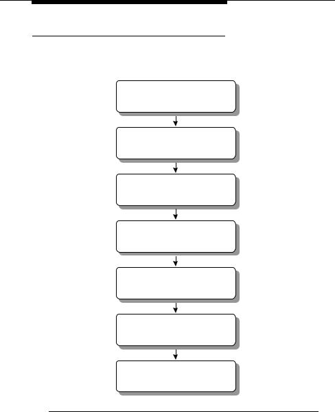
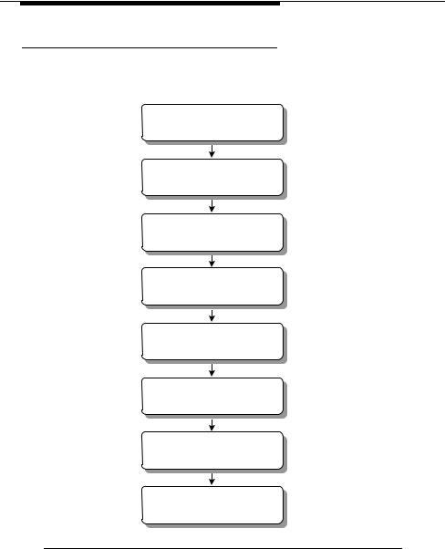
CU232 Installation Workflow
The following workflow illustrates the procedure that may be followed when installing the CU232.
Fasten the mounting bracket to the support
Attach the CU232 to the mounting bracket
Adjust the direction and downtilt of the CU232
Tighten the CU232 attachment to the mounting bracket
Connect the power/data cable to the CU232
Connect the power/data cable to the data/power adapter
Connect the power/data adapter to the PC or LAN
Figure 1-4 CU232 Installation Workflow
WaveACCESS NET 2400 Installation Guide |
1-11 |
Introducing the WaveACCESS NET 2400
System
Remote Unit Installation Workflow
The following workflow describes the procedure that may be followed when installing the xDR232.
Identify the xDR232 site and prospective (intended) base station
Identify the optimal xDR232 mounting location
Install the mounting hardware and attach the xDR232
Point the unit in the direction of the base station
Connect the power/data cable between the xDR232 and adapter
Connect the power/data adapter to the PC or LAN
Power up the xDR232
Align and fasten the xDR232
Figure 1-5 xDR232 Installation Workflow
1-12 |
WaveACCESS NET 2400 Installation Guide |

|
|
2 |
|
WaveACCESS NET 2400 Base |
|||
|
|||
Station Site Preparation |
|
||
THIS IS AN INCOMPLETE DRAFT.
This chapter describes the requirements and specifications that must be satisfied when preparing a site for the installation of the WaveACCESS NET CU232 units (base station).
About this chapter:
Clearances and Space Requirements, page 2-2, describes the clearances and space requirements for installing the CU232.
Tower Pipe Installation, page 2-6, describes
Electrical Power Requirements, page 2-7, provides guidelines for the installation of electrical power to the base station.
Grounding and Lightning Protection Bonding Requirements, page 2-8, describes the grounding and lightning protection requirements for a WaveACCESS NET base station.
WaveACCESS NET 2400 Installation Guide |
2-1 |

WaveACCESS NET 2400 Base Station Site
Preparation
Clearances and Space
Requirements
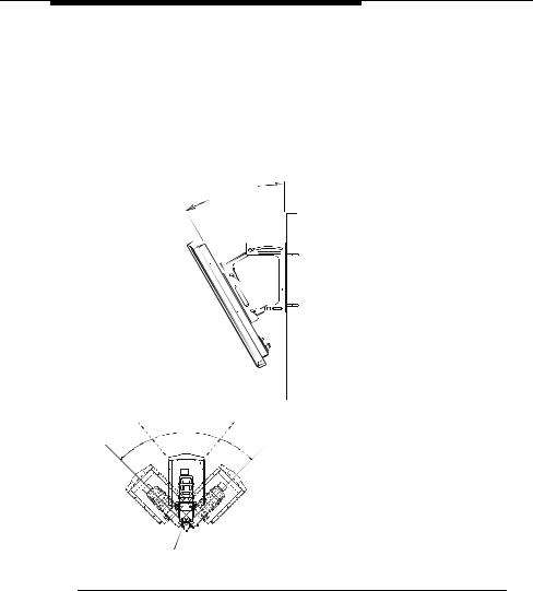
The intended installation area must include enough space to accommodate the CU232. Figure 2-1 shows the space required for the CU232 installation.
21.2" |
UNOBSTRUCTED VIEW |
||
|
C |
|
|
|
40o |
L |
40o |
|
45o |
|
45o |
Grounding |
MAX. |
|
MAX. |
Stud |
PIVOT |
|
PIVOT |
|
ANGLE |
||
|
ANGLE |
|
|
25"
27.5"
3" Min |
|
WALL |
TOP VIEW |
|
Figure 2-1 Space Required for CU232
Dimensions and Weight of the CU232
The dimensions and weight of the CU232 are displayed in Table 2-1.
2-2 |
WaveACCESS NET 2400 Installation Guide |

WaveACCESS NET 2400 Base Station Site
Preparation
Table 2-1 |
Dimensions and Weight of the CU232 As-Installed |
||||
|
|
|
|
|
|
Equipment |
|
Width |
Depth |
Height |
Weight |
|
|
|
|
|
|
CU232 |
|
12 in |
5 in |
30 in |
13 lbs |
|
|
30 cm |
13 cm |
76 cm |
6 kg |
|
|
|
|
|
|
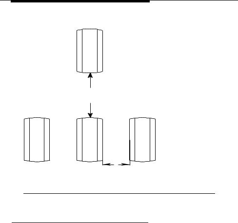
Minimum Space Required Between Multiple
CU232s
When multiple CU232s are installed, the space required between each CU232 must be:
■Horizontal space of 31 centimeters (12 inches).
■Vertical space of 1 meter (3 feet).
WaveACCESS NET 2400 Installation Guide |
2-3 |
WaveACCESS NET 2400 Base Station Site
Preparation
Figure 2-2 shows the spacing requirements for multiple CU232s.
1 METER (Min.)
1/3 METER (Min.)
Figure 2-2 Multiple CU232 Spacing Requirements
CU232 Environmental Requirements
The environmental requirements must be within the limits specified in Table 2-2, in order for the CU232 to operate properly.
2-4 |
WaveACCESS NET 2400 Installation Guide |

WaveACCESS NET 2400 Base Station Site
Preparation
Table 2-2 CU232 Environmental Requirements
Environmental Conditions
Minimum Ambient |
- 40.0 °C (- 40 °F) |
Temperature |
|
|
|
Maximum Ambient |
+ 46.0 °C (+ 114.8 °F) |
Temperature |
|
|
|
Minimum Relative |
10% |
Humidity |
|
|
|
Maximum Relative |
100% |
Humidity |
|
|
|
WaveACCESS NET 2400 Installation Guide |
2-5 |

WaveACCESS NET 2400 Base Station Site
Preparation
Tower Pipe Installation
It is recommended that towers have a wind rating of 100mph with 5, 10, or 15 CU232s. Each CU232 will experience 80 kg (175 lbs) of wind load at 100mph w/wind factor normal to CU232. The tower should be able to support 1, 2, or 3 sets of CU232s.
The installation height of the antenna must be approximately 15 m above the surrounding average building height, or as specified by the field RF engineer.
The pipes to which the CU232s will be attached should be mounted either on a tower, or on the sides of a building near the roofline, at a height specified by the field RF engineer.
When tower installation is performed, the pipe should be installed around the tower with an angular separation of 72 degrees. In certain instances, it may not be possible to install the support pipe at 72 degree intervals. The ability to swing the CU232 from side to side over an arc of approximately 45 degrees is required. One of the support pipes should be mounted on the tower so that it faces North. A subsequent pipe can then be installed at 72 degree increments from the reference Northward facing pipe.
When performing the installation of five CU232s on a building, the support pipes should be located on a common wall. The other three CU232s can be installed on the other three sides of the building. The clearance requirements should comply with
Figure 2-1.
The minimum distance between any CU232 support pipe and other wireless telecommunication equipment should be
two meters.
2-6 |
WaveACCESS NET 2400 Installation Guide |

WaveACCESS NET 2400 Base Station Site
Preparation
Electrical Power Requirements
This section provides guidelines for the installation of AC or 48VDC electrical power to the base station, as follows:
■General Requirements, page 2-7.
■CU232 Power Requirements, page 2-7.
General Requirements
All the AC wiring and over-current protection must be provided in accordance with the National Electric Code (NFPA-70) and local electrical codes. An appropriate earth-ground connection is required before the commercial AC service can be connected. The base station AC input power is single phase, nominal 120/208 or 120/240 Vrms, 50/60 Hz. Nominal voltage is defined as 120 Vrms between line(s) to ground, and 208 Vrms or 240 Vrms line to line.
CU232 Power Requirements
Each CU232 requires 24-48VDC, 15 Watts, which is supplied by the power/data adapter.
WaveACCESS NET 2400 Installation Guide |
2-7 |
WaveACCESS NET 2400 Base Station Site
Preparation
Grounding and Lightning
Protection Bonding Requirements
This section provides information on grounding and lightning protection requirements for a WaveACCESS NET base station, as follows:
■General Requirements, page 2-7.
■Lightning Protection, page 2-10.
General Requirements
The WaveACCESS NET base stations are susceptible to lightning surges due to their association with towers and antennas. Therefore, it is imperative that all base station components be properly grounded, providing a low impedance path to earth. The grounding conductors must be as straight and short as possible and should not have any sharp bends or loops.
The CU232 cable shield must be bonded at the top and bottom of the vertical run, and where it comes near the equipment. The tower or metallic support of the antenna must also be bonded to the grounding system. In addition, the surge protection device must be bonded to a nearby ground bus bar that is connected directly to the grounding electrode system.
All metallic objects within 2 meters (6 feet) of the grounded equipment must be bonded to the grounding system.
All base station equipment must be bonded to a grounding electrode system, for example, buried ring ground, copper clad rod, electrolytic rods, metallic water pipe, and so on.
2-8 |
WaveACCESS NET 2400 Installation Guide |

WaveACCESS NET 2400 Base Station Site
Preparation
The minimum requirement for buried ground conductors is #2 AWG bare, solid, tinned copper wire. Exterior ground
conductors must be either solid, bare, tinned copper or stranded, insulated (for sunlight resistance) copper cable. The interior ground cable must be stranded copper with green insulation type THAWN or equivalent.
All grounding system material, namely, cable, connectors, buses, and so on, must be made of high quality materials that are resistant to deterioration and that require little or no maintenance.
An exothermic weld is recommended for grounding connections, where practical. All below-grade connections must be exothermically welded. In addition, compression type, long barrel, two-hole (0.75" center) lugs or double crimp “C” Taps are also acceptable. The metal contacts to which connections are made must have a bare bright finish, and be coated with an anti-oxidation material.
Refer to Lucent Technologies 401-200-115, Grounding and Lightning Protection Guidelines for Wireless System Base Stations, for detailed requirements regarding grounding and lightning protection bonding.
!WARNING:
The equipment warranty can be voided if the guidelines detailed in the National Electric Code (NFPA 70), Standard for Installation of Lightning Protection System (NFPA 780, 1995 edition), Lucent Technologies 401-200-115, and Lucent Technologies Equipment Drawings referred to in this document are not followed.
Refer to Appendix C for a checklist of the verification of the grounding requirements that can be performed.
WaveACCESS NET 2400 Installation Guide |
2-9 |
WaveACCESS NET 2400 Base Station Site
Preparation
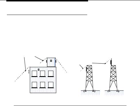
Lightning Protection
The preferred method of reducing the risk of lightning strikes is avoidance. CU232s and remote units must be mounted within the 45o lightning protection cones, as shown in Figure 2-3. The 45o lightning protection cone also applies to tower-mounted units.
Cone of Protection |
|
|
45o |
Cone of Protection |
45o |
|
45o |
|
|
45o |
|
45o |
|
|
|
A |
B |
Figure 2-3 Lighting Protection Cone
2-10 |
WaveACCESS NET 2400 Installation Guide |

|
|
3 |
|
Installing the CU232 |
|||
|
|||
THIS IS AN INCOMPLETE DRAFT.
This chapter describes the installation procedures of the
WaveACCESS NET CU232.
About this chapter:
Installation Requirements for the CU232, page 3-2 describes the physical installation requirements of the WaveACCESS NET CU232.
Mounting and Tilting the CU232, page 3-5 describes the procedure for mounting and tilting the WaveACCESS NET CU232.
Connecting the Power/Data Cable, page 3-8 describes the procedure for connecting the power/data cable to the
WaveACCESS NET CU232.
Connecting the Power/Data Cable to the Adapter, page 3-9 describes the procedure for connecting the power/data cable to the power/data adapter.
Connecting to the PC or LAN, page 3-9 describes connecting the CU232 to your computer or network by installing the power/data cable between the CU232 and the power/data adapter.
Powering Up the CU232, page 3-9 describes the procedure for powering up the CU232.
WaveACCESS NET 2400 Installation Guide |
3-1 |

Installing the CU232
Installation Requirements for the CU232
The qualifications required for an installer are similar to those required to install standard office telecommunications equipment. Installers should be familiar with local construction techniques, requirements, and regulations associated with the installation of cabling and brackets in an urban or suburban environment, and must be able to run simple diagnostic procedures.
This section describes the physical installation requirements of the
WaveACCESS NET CU232, as follows:
■Installation Items Provided by Lucent, page 3-2.
■Additional Installation Items Required, page 3-3.
Installation Items Provided by Lucent
The following items are included in the Lucent Technologies installation kit:
■WaveACCESS NET CU232 wireless central unit.
■CU232 mounting bracket.
■One power/data adapter complete with a 5-foot (1.5m) cord.
■A software diskette.
■One power/data cable of 10m, 30m, or 100m.
■This WaveACCESS NET 2400 Installation Guide.
■A CD-ROM containing documentation.
When an additional antenna is required, you will also receive a second package that includes the WaveACCESS NET antenna kit that was ordered with the system.
3-2 |
WaveACCESS NET 2400 Installation Guide |

Installing the CU232
NOTE:
If any of these items are incomplete or missing, you might not be able to install the WaveACCESS NET CU232. In this case please contact your nearest Technical Support Center. Refer to Chapter 8 ”Technical Support” for more information.
The following additional items are provided by Lucent Technologies for the installation team:
■Cable tester (comcode #).
■Power/data cable (comcode 408158830).
■CU232 electrical power tester (comcode #).
Additional Installation Items Required
The following list describes the items that are not provided by Lucent Technologies, but are required for installation.
■Bolts, mounting hardware
■Drill and drill bits
■Grounding braid
■Nut drivers
■Ladder
■Pliers
■Long nose pliers
■Screwdrivers
■Safety glasses
■Cable ties
WaveACCESS NET 2400 Installation Guide |
3-3 |

Installing the CU232
■Specialized wire stripping tools:
■Precision wire stripper
OK Industries, model ST-550 Details from www.okindustries.com
Available from: Newark Electronics, Tel. 800-463-9275
■Cable jacket cutter
Ideal Cyclops, model 45-514
■Data cable cutter
Ideal Cyclops, model 45-074
Details from www.idealindustries.com
■Miniature needle nose pliers
■Phillips No. 1 screwdriver
■Flat screwdriver with 2.3 to 2.5 mm blade
Available from: Allied Electronics, Tel. 800-433-5700
■Wrenches
■Torque wrench (40 in-lb capacity)
■Multimeter
■Cutters
■Downtilt meter
■Utility knife
■Tape measure
■Pipe, U-bolts, and so on.
■Connections to Ethernet
■Compass or other directional equipment
3-4 |
WaveACCESS NET 2400 Installation Guide |

Installing the CU232
Mounting and Tilting the CU232
The WaveACCESS NET CU232 should be mounted in front of a wall or structure, to minimize the interference of other signals from behind the unit.
The CU232 mounting bracket can be fastened in the following ways:
■To a 2 m (6 ft.) long, 5 cm (2 in) diameter “schedule 40” pole, using two of the tension belts provided along with the mating nuts and split lock washers (preferred technique).
■To a pole that is rigidly fastened to a tower (optional technique).
The location of the CU232 bracket supports will be provided by the site preparation team, in compliance with the site preparation guidelines, as described in Chapter 2.
Prior to installation, record or scan the barcode that includes the serial number and MAC addresses of the CU232s, and identify the azimuth (horizontal) and elevation (downtilt) in which each CU232 will be pointing when installed. Provide the orientation information to the RF network planner.
WaveACCESS NET 2400 Installation Guide |
3-5 |
Installing the CU232
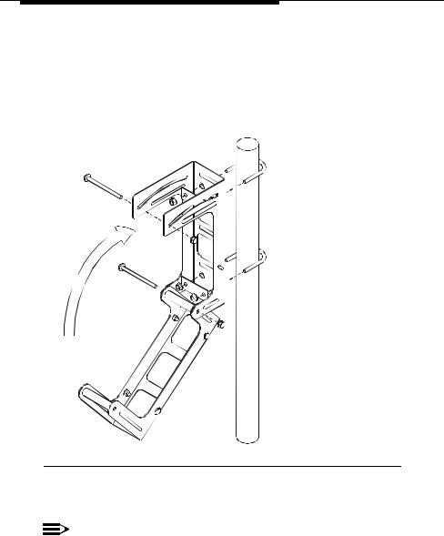
To mount the CU232:
1.Fasten the CU232 mounting bracket to the pole with the two straps. You can improve the access to the fastening hardware by opening the CU232 mounting to the "unfolded" configuration, as shown in Figure 3-1. The mounting bracket should face in the general direction of the remote unit.
Figure 3-1 CU232 Mounting Bracket Fastened to Pole
2. Mount and partially fasten the CU232 to the bracket.
NOTE:
Ensure that you perform steps 3 and 4 before tightening the straps completely.
3-6 |
WaveACCESS NET 2400 Installation Guide |
Installing the CU232
3.Adjust the direction of the CU232 by rotating it to the required azimuth (horizontal) orientation.
4.Using the downtilt meter adjust the downtilt of the CU232 according to the RF planning requirements for the site.
5.Tighten the fastening belts of the CU232 when it is correctly oriented.
6.Tighten the pivot bolts.
DOWNTILT ANGLE
ADJUST PIVOT ANGLE
TOP VIEW
Figure 3-2 CU232 Tilt Angle
WaveACCESS NET 2400 Installation Guide |
3-7 |
 Loading...