

Page 1

CCS Technical Documentation
RH-48 Series Transceivers
Troubleshooting — Antenna
Issue 1 11/2003 Confidential © 2003 Nokia Corporation
Page 2

RH-48
Troubleshooting — Antenna CCS Technical Documentation
Contents
Page No
Troubleshooting - Antenna ............................................................................................ 3
Relevant Documents ....................................................................................................3
Failures and Corrective Measures ...............................................................................3
Appearance of phone................................................................................................. 3
Internal Antenna Missing ............................................................................................4
Damaged RF Feed Pin or Ground Pin .........................................................................4
Wrong Internal Antenna Installed ...............................................................................5
Obstructed RF Feed or Ground Pads for Internal Antenna, or IHF Speaker Pads ......6
Grounding of Display Frame .......................................................................................7
Grounding of RUIM Card Flap ...................................................................................8
RF Connector Failure ..................................................................................................8
Page 2 ©2003 Nokia Corporation Confidential Issue 1 11/2003
Page 3
RH-48
CCS Technical Documentation Troubleshooting — Antenna
Troubleshooting - Antenna
This troubleshooting guide addresses potential failures that will affect antenna performance of the RH-48 phone, and discusses methods for correction of these failures.
Relevant Documents
C-Max Antenna RF Specifications and Plan (DHS02726-EN-1.0)
Failures and Corrective Measures
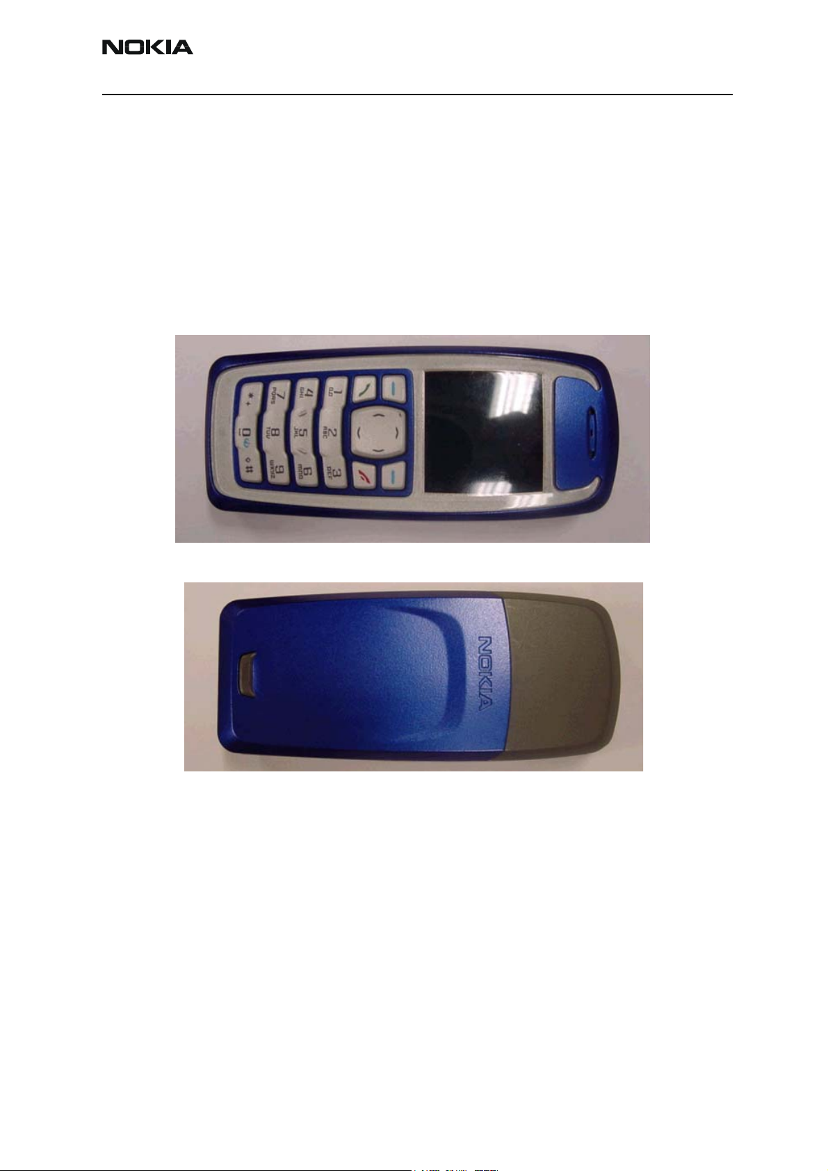
Appearance of phone
Figure 1: Front view of RH-48 (Model 3105)
Figure 2: Back view of RH-48 (Model 3105)
Issue 1 11/2003 ©2003 Nokia Corporation Confidential Page 3
Page 4

RH-48
Troubleshooting — Antenna CCS Technical Documentation
Internal Antenna Missing
Figure 3: RH-48 chassis assembly
If the internal antenna is missing, install one. If the radiator looks obviously damaged,
then replace the internal antenna.
If no internal antenna is installed, the antenna gain will be degraded by more than
25dB.
Damaged RF Feed Pin or Ground Pin
Figure 4: Top and bottom views of the RH-48 internal antenna
If either the RF feed pin or ground pin are broken or bent such that either pin will not
touch the PWB, then the internal antenna must be replaced. If the springs for the RF or
ground pin appear damaged, then the internal antenna must be replaced. If the slot in
the radiator has a significantly different shape, then the correct internal antenna must
be installed. If there is any other obvious damage to the radiator (dents, corrosion), then
the antenna should be replaced. If the pin gets stuck or has excessive friction in the plastic tube/guiding feature, then the spring will not work properly and the antenna should
be replaced.
Page 4 ©2003 Nokia Corporation Confidential Issue 1 11/2003
Page 5

RH-48
CCS Technical Documentation Troubleshooting — Antenna
If the RF feed doesn’t touch the PWB, then the antenna gain will degrade by more than
25dB. If the ground pin doesn’t touch the PWB, then the antenna gain may degrade
about 5 to 10dB.
If either of the IHF speaker pins is damaged or if the IHF speaker is nonfunctioning, then
the antenna module should be replaced.
Wrong Internal Antenna Installed
RH-48 antenna
RH-19 antenna
RH-48 antenna
RH-48 antenna
Figure 5: Top views of the RH-19 and RH-48 antennas
RH-19 antenna
Figure 6: Bottom views of RH-19 and RH-48 antennas
RH-48 antenna
The RH-48 and RH-19 antennas are similar in appearance. The important visual difference in the antennas is that the slot pattern is very different. Also, the RH-48 antenna is
thicker than the RH-19 antenna and also has a spacer on its back side.
If the wrong antenna is installed, install the correct one.
Issue 1 11/2003 ©2003 Nokia Corporation Confidential Page 5
Page 6

RH-48
Troubleshooting — Antenna CCS Technical Documentation
Obstructed RF Feed or Ground Pads for Internal Antenna, or IHF Speaker Pads
Pad for ground pin
Pad for RF pin
IHF speaker pads
Figure 7: PWB layout of RF feed and ground pads and IHF speaker pads
If the RF feed pad is obstructed, removed, or covered, then the RF feed pin will not touch
the PWB and the antenna gain will degrade by more than 25dB. If the ground pad is
obstructed, removed, or covered, then the ground pin will not touch the PWB and the
antenna gain may degrade by about 5 to 10dB. If corrosion is present or the pad is missing, most likely the PWB and phone needs to be replaced. If either pad is obstructed or
covered, the pad should be cleared and/or cleaned.
If the Internal Hands Free (IHF) speaker pads are obstructed, removed, or covered, the IHF
speaker will not produce sound. If corrosion is present or the pad is missing, most likely
the PWB and phone needs to be replaced. If either pad is obstructed or covered, the pad
should be cleared and/or cleaned.
Page 6 ©2003 Nokia Corporation Confidential Issue 1 11/2003
Page 7

RH-48
CCS Technical Documentation Troubleshooting — Antenna
Grounding of Display Frame
Figure 8: Display assembly
Note that the display frame is grounded to the PWB through the two top screws. The
grounding of the display frame will impact the radiation performance of the phone. If
the screws are loose, then tighten them. If the screw bosses are stripped, then the chassis will need to be replaced. If the screws are missing, install new ones.
The middle screws should not touch the metal in the LCD frame, the metal shield over
the keypad, the PWB, or the RF shield. When driving in these screws, be sure to drive
them in straight. If the screws are driven in at an angle, it is much more likely that the
screws will touch the PWB or the RF shield. If this happens, then antenna performance
could change by about 1dB.
Issue 1 11/2003 ©2003 Nokia Corporation Confidential Page 7
Page 8

RH-48
Troubleshooting — Antenna CCS Technical Documentation
Grounding of RUIM Card Flap
Figure 9: Conductive sticker grounding RUIM card flap to RF shield
The RUIM card flap needs to be grounded to the RF shield with a conductive sticker. The
shape and location of the conductive sticker is shown in the figure above. If the conductive sticker is missing or ripped, it needs to be replaced.
If the sticker is damaged or missing, then the radiated sensitivity could be reduced
by 4-8dB.
RF Connector Failure
The RF connector could fail by not connecting the RF input to the RF output of the RF
connector. If this happens, then the antenna gain will degrade by about 25dB. This can
be checked by testing for DC conductivity between the RF input and RF output of the RF
connector. Note the DC conductivity test must be done without any cable attached to
the RF connector. Since the RF connector is also a switch, the RF output will be disconnected from the RF input when a cable is inserted into the RF connector. When a cable is
inserted, the RF input is connected to the RF connector. The location is shown in
Figure 6.
RF input — connector to duplexor
RF output — connects to antenna pad through vias
RF connector — connects to coaxial cable
If the RF input is not connected properly to the RF output, the RF connector must be
replaced.
Page 8 ©2003 Nokia Corporation Confidential Issue 1 11/2003
 Loading...