

Page 1

Nokia Customer Care
3-Service Sof tware
Instructions
ISSUE 1 09/2004 Copyright© 2004 Nokia Corporation. All rights reserved
Page 2

RH-59/60
Nokia Customer Care 3-Service Software Instructions
[This page left intentionally blank]
2 COMPANY CONFIDENTIAL ISSUE 1 09/2004
Copyright © 2004 Nokia. All Rights Reserved.
Page 3

RH-59/60
Nokia Customer Care
Table of Contents
Page No
Quick Guide for Phoenix Service SW Installation............................................ 7
Phoenix installation steps in brief....................................................................... 7
Phoenix Service SW............................................................................................9
Before installation .............................................................................................. 9
Startup ............................................................................................................. 10
Update installation of Phoenix ......................................................................... 15
How to uninstall Phoenix.................................................................................. 16
Repair .............................................................................................................. 18
Data Package for Phoenix (Product Specific) ................................................19
Before installation ............................................................................................ 19
Installation of Phoenix Data Package (Product Specific)................................. 20
How to uninstall Data Package........................................................................ 24
How to configure users .................................................................................... 25
How to Manage Connections........................................................................... 27
Manual Settings .............................................................................................28
How to Update Flash Support Files for FPS-8* and FLS-4S*........................ 31
Before installation ............................................................................................ 31
Installing the flash support files........................................................................ 31
How to update the FPS-8* Flash Prommer SW............................................... 35
FPS-8 Activation and Deactivation.................................................................. 37
Activation ......................................................................................................... 37
Deactivation..................................................................................................... 39
JBV-1 Docking Station SW............................................................................... 40
Before installation ............................................................................................ 40
Installing SW needed for the JBV-1 SW update.............................................. 41
Updating the JBV-1 Docking Station software................................................. 45
Service Tool Concept For Baseband Tuning Operations.............................. 47
Service concept for baseband tunings............................................................. 48
Baseband Tuning operations........................................................................... 49
Energy management tuning............................................................................. 49
LCD contrast tuning......................................................................................... 51
Receiver Tuning: Quick Guide for Tuning With Phoenix .............................. 53
General remarks.............................................................................................. 53
ISSUE 1 09/2004 COMPANY CONFIDENTIAL 3
Copyright © 2004 Nokia. All Rights Reserved.
Page 4

RH-59/60
Nokia Customer Care
Service Tool Concept for RF Tuning Operations........................................... 54
Autotuning......................................................................................................... 55
Set loss ..........................................................................................................56
Environment..................................................................................................... 57
Protection .......................................................................................................58
Receiver Manual Tuning................................................................................... 59
RX channel select filter calibration................................................................... 59
RX Calibration.................................................................................................. 60
RX band filter response compensation............................................................ 64
Rx Am suppression.......................................................................................... 68
RX DTOS balance calibration.......................................................................... 72
RH-59 Manual Alignment with Phoenix........................................................... 75
RX calibration................................................................................................... 75
GSM1800 RX calibration ...............................................................................76
RX channel select filter .................................................................................... 77
RX band filter response ................................................................................... 78
Tx power tuning ............................................................................................... 79
TX power tuning GSM ....................................................................................79
TX power tuning GSM1800 ............................................................................82
I/Q tuning ......................................................................................................... 84
RF control ........................................................................................................ 86
Call testing....................................................................................................... 87
RH-60 Manual Alignment with Phoenix........................................................... 89
RX calibration................................................................................................... 89
Tx power tuning ............................................................................................... 92
TX power tuning GSM ....................................................................................92
TX power tuning GSM1900 ............................................................................95
I/Q tuning ......................................................................................................... 97
RF control ...................................................................................................... 100
Call testing..................................................................................................... 101
Flashing Setup Instructions........................................................................... 103
POS (Point of Sale) flash concept ................................................................. 103
Flash Concept with Flashing adapter............................................................. 104
Module jig concept......................................................................................... 105
JBV-1 flash concept....................................................................................... 106
Service concept ............................................................................................. 107
Parallel flash concept..................................................................................... 108
List of Figures
Page No
Fig 1 RF tuning setup ........................................................................................... 50
Fig 2 Autotune component in TSS architecture .................................................... 51
4 COMPANY CONFIDENTIAL ISSUE 1 09/2004
Copyright © 2004 Nokia. All Rights Reserved.
Page 5

RH-59/60
Nokia Customer Care
Fig 3 Autotune menu in Phoenix........................................................................... 51
Fig 4 Autotune menu - RX/TX menu..................................................................... 52
Fig 5 Set Loss menu............................................................................................. 52
Fig 6 Loss values..................................................................................................53
Fig 7 Setup environment....................................................................................... 54
Fig 8 POS flash .................................................................................................... 99
Fig 9 Flash concept with flashing adapter............................................................. 100
Fig 10 Module jig concept..................................................................................... 101
Fig 11 JBV-1 Flash concept.................................................................................. 102
Fig 12 Service concept.......................................................................................... 103
Fig 13 Parallel flash concept................................................................................. 104
ISSUE 1 09/2004 COMPANY CONFIDENTIAL 5
Copyright © 2004 Nokia. All Rights Reserved.
Page 6

Nokia Customer Care
RH-59/60
[This page left intentionally blank]
6 COMPANY CONFIDENTIAL ISSUE 1 09/2004
Copyright © 2004 Nokia. All Rights Reserved.
Page 7
RH-59/60
Nokia Customer Care
Quick Guide for Phoenix Service SW Installation
■ Phoenix installation steps in brief
These are the basic steps to install the Phoenix
-Connect a DK2 Dongle or FLS-4S POS Flash Device
-Install the Phoenix Service SW
-Install the Data Package for Phoenix
-Configure users
-Manage connection settings (depends on the tools you are using)
-Phoenix is now ready for FLS-4S Point Of Sales Flash Device use.
-If you use FPS-8:
--Update FPS-8 SW
--Activate FPS-8
--Update JBV-1 Docking Station SW (only when needed)
Phoenix is now ready to be used also with FPS-8 flash prommer and other tools
ISSUE 1 09/2004 COMPANY CONFIDENTIAL 7
Copyright © 2004 Nokia. All Rights Reserved.
Page 8

RH-59/60
Nokia Customer Care
The Phoenix Service Software installation contains:
-Service software support for all phone models included in the package
-Flash update package files for FPS-8* and FLS-4S programming devices
-All needed drivers for:
-- DK2 dongle
-- FLS-4S point of sales flash device
-- USB devices
Separate installation packages for flash update file s and drivers are also available, but it is not
necessary to use them unless updates appear between Phoenix Service SW releases. If separate update packages are used, they should be used after Phoenix and data packages have
been installed.
The phone model specific data package includes all changing product specific data:
Product software Binary files
Files for type label printing
Validation file for the Faultlog repair data reporting system
All product specific configuration files for Phoenix software components
Please refer to Service Manual and Technical Bulletins for more information concerning phone
model specific service tools and equipment setup.
8 COMPANY CONFIDENTIAL ISSUE 1 09/2004
Copyright © 2004 Nokia. All Rights Reserved.
Page 9
RH-59/60
Phoenix Service SW
■ Before installation
• Check that a Dongle is attached to the parallel port of your computer .
• Download the installation package/application file produced in wk 33, 2004 or
higher version (e.g. phoenix_service_sw_a13_2004_08_5_42.exe) to your computer (eg C:\TEMP)
• Close all other programs
• Run the application file produced in wk 33, 2004 or higher version (e.g.
phoenix_service_sw_a13_2004_08_5_42.exe) and follow the instructions on the
screen
• Administrator rights may be required to be able to install Phoenix depending on
the Operating System
• If uninstalling or rebooting is needed at any point, you will be prompted by the Install Shield program.
Nokia Customer Care
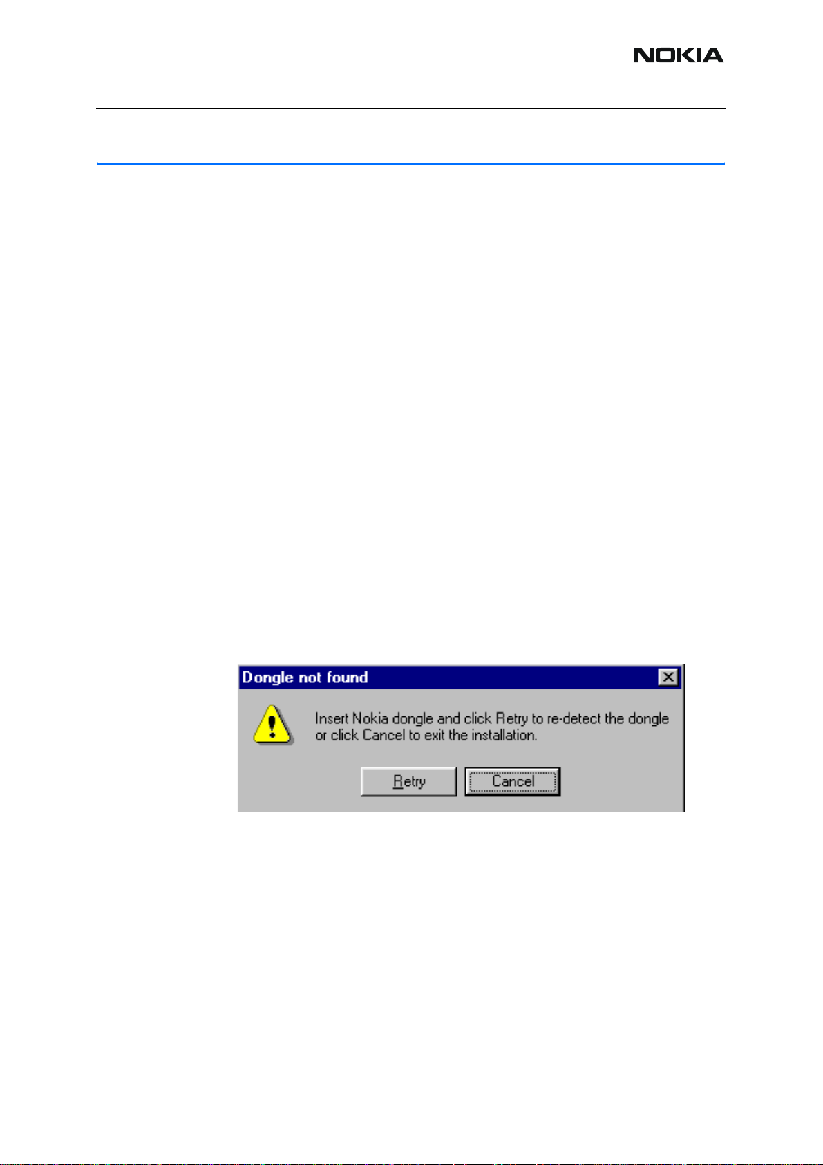
If at any point during installation you get this message, Dongle is not found and inst allation can´t
continue.
Possible reasons may be defective or too old PKD-1Dongle (five digit serial number Dongle
when used with FPS-8 Prommer) or that the FLS-4S POS Flash Dongle is defective or powe r
to it is not supplied by external charger.
Check the COM /parallel ports used first! After correcting the problem Installation can be restarted.
ISSUE 1 09/2004 COMPANY CONFIDENTIAL 9
Copyright © 2004 Nokia. All Rights Reserved.
Page 10
RH-59/60
Nokia Customer Care
■ Startup
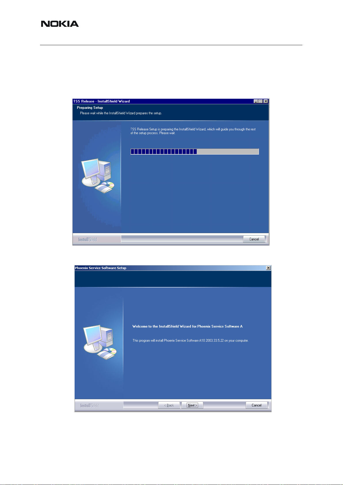
Run the application file produced in wk 33, 2004 or higher version e.g.
phoenix_service_sw_a13_2004_08_5_42.exe to start installation. Install Shield will prepare.
.
Click "Next" in Welcome dialog to continue.
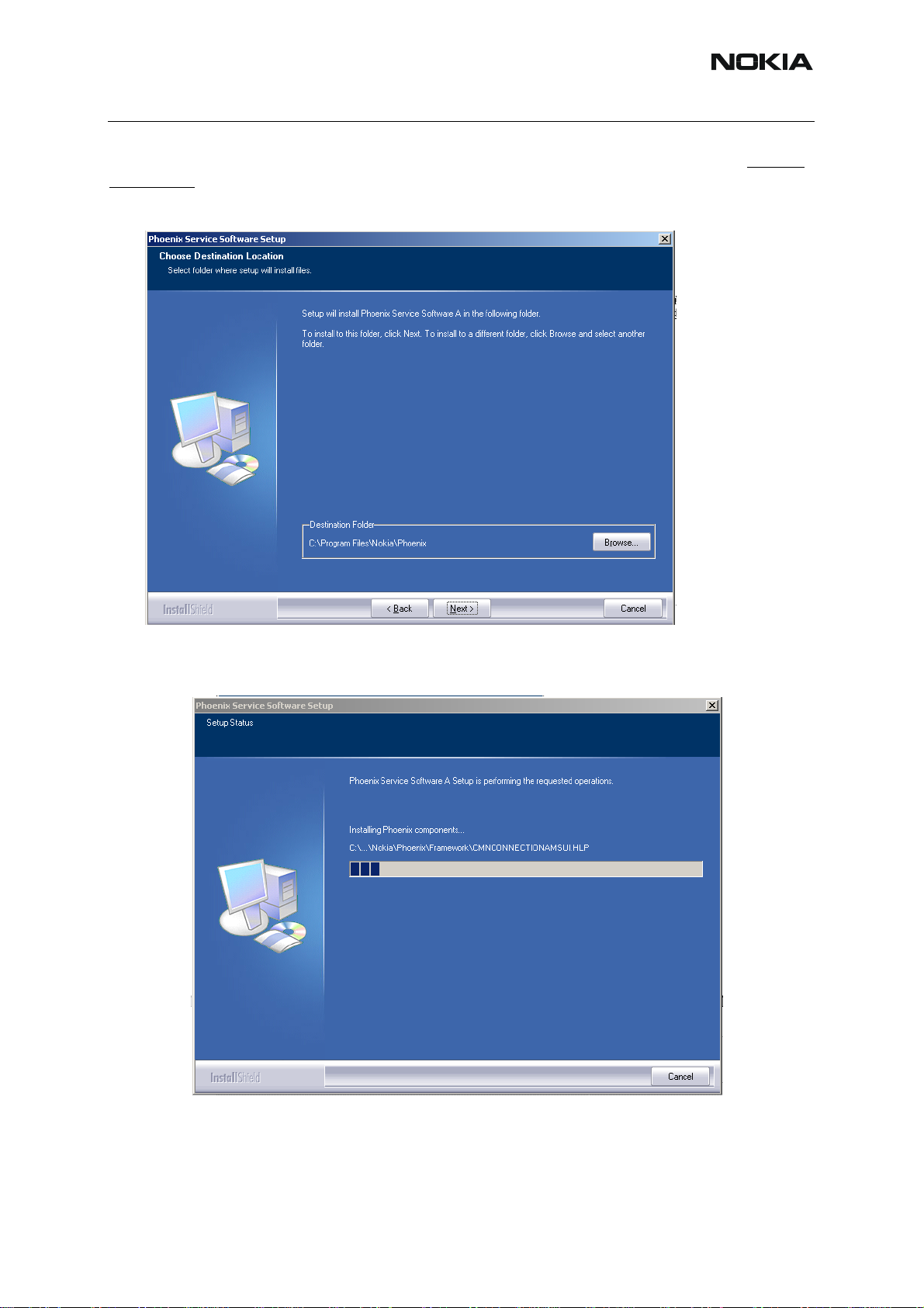
Choose destination folder, it is recommended to use the default folder C:\ProgramFiles\No-
kia\Phoenix.
10 COMPANY CONFIDENTIAL ISSUE 1 09/2004
Copyright © 2004 Nokia. All Rights Reserved.
Page 11
RH-59/60
Nokia Customer Care
Choose “Next” to continue. You may choose another location by selecting “Browse” (not recommended)
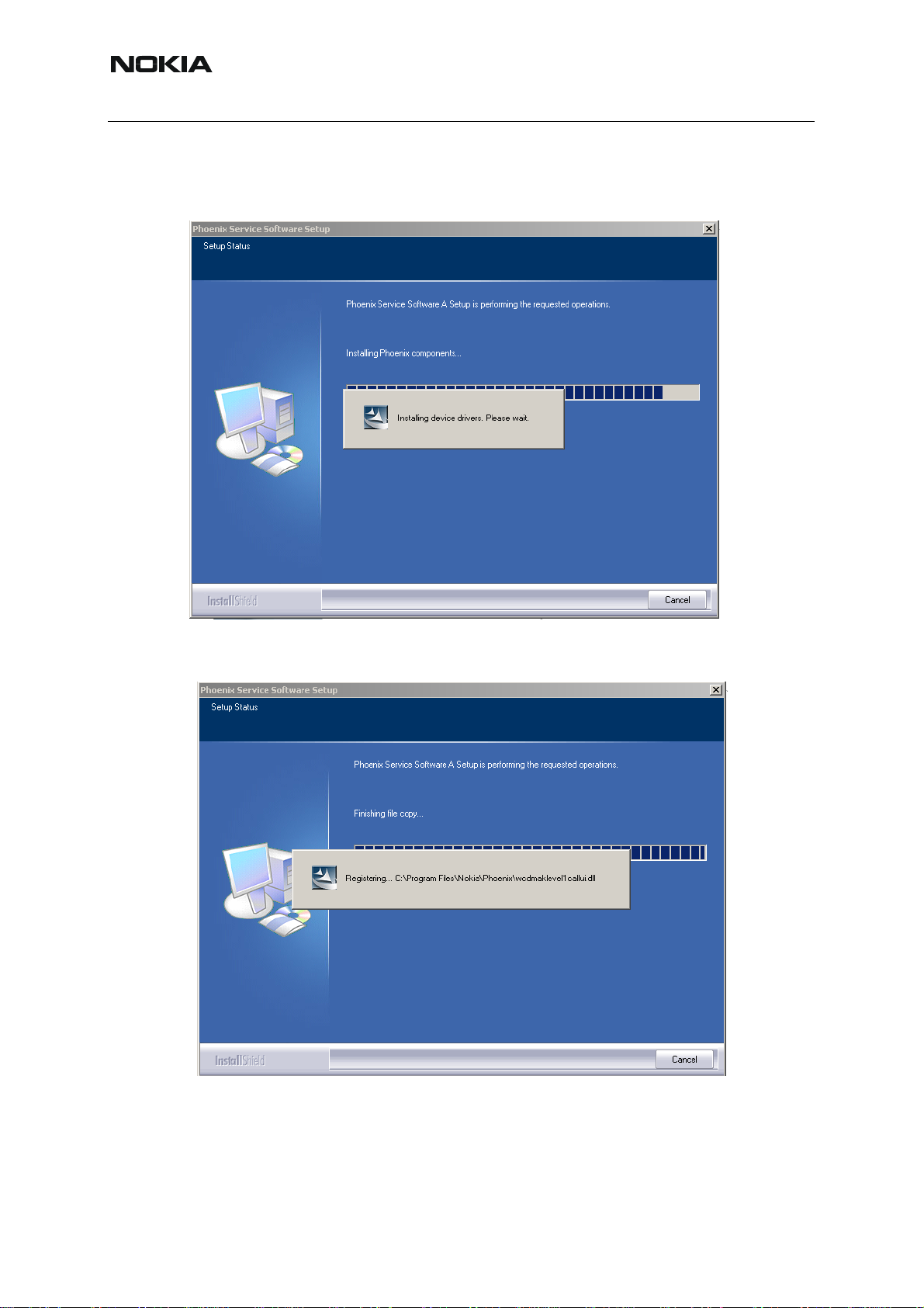
Setup copies the components, progress of the setup is shown. Please wait…
ISSUE 1 09/2004 COMPANY CONFIDENTIAL 11
Copyright © 2004 Nokia. All Rights Reserved.
Page 12
RH-59/60
Nokia Customer Care
Drivers will be installed and updated, please wait.. the process may take several minutes to
complete.
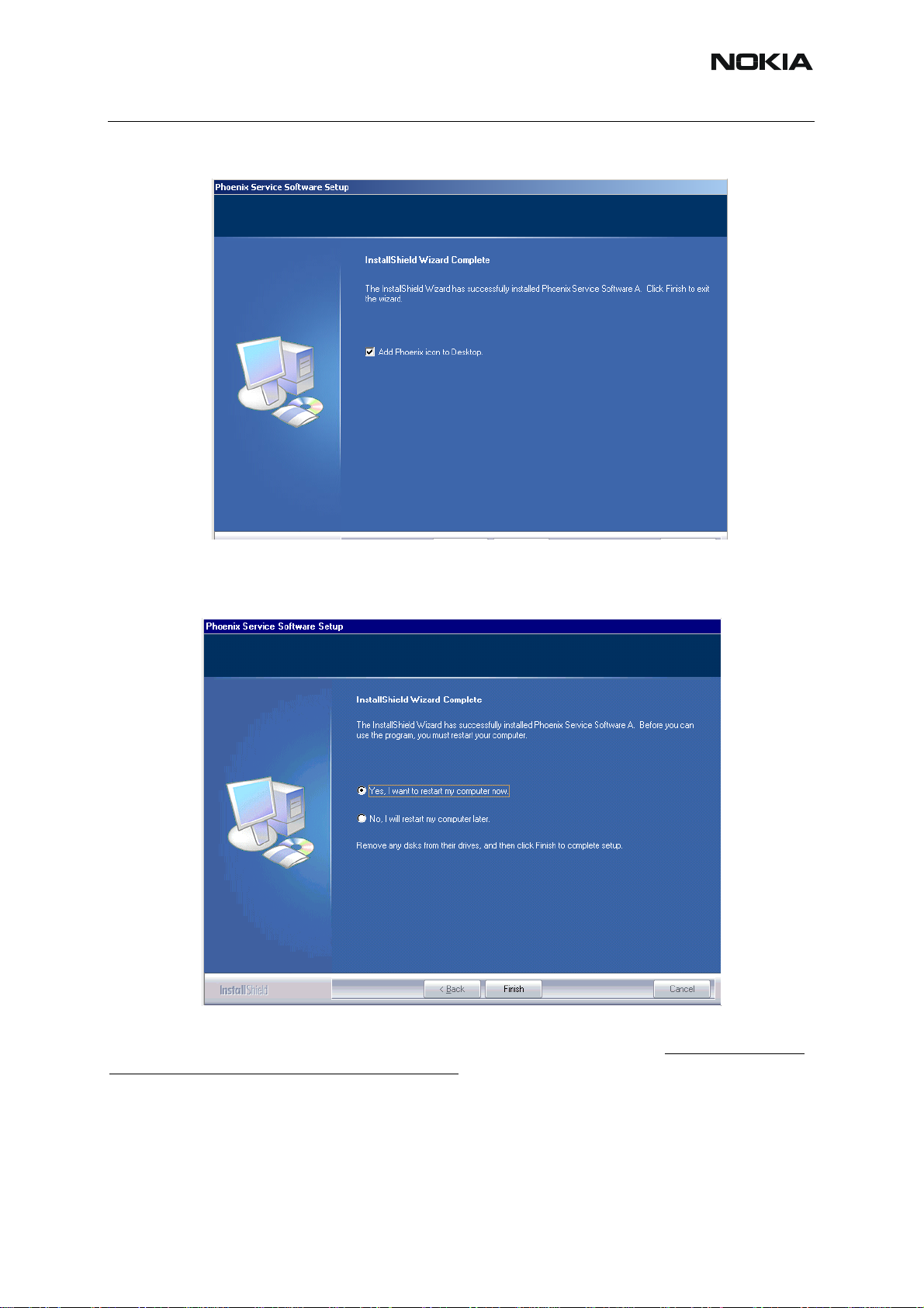
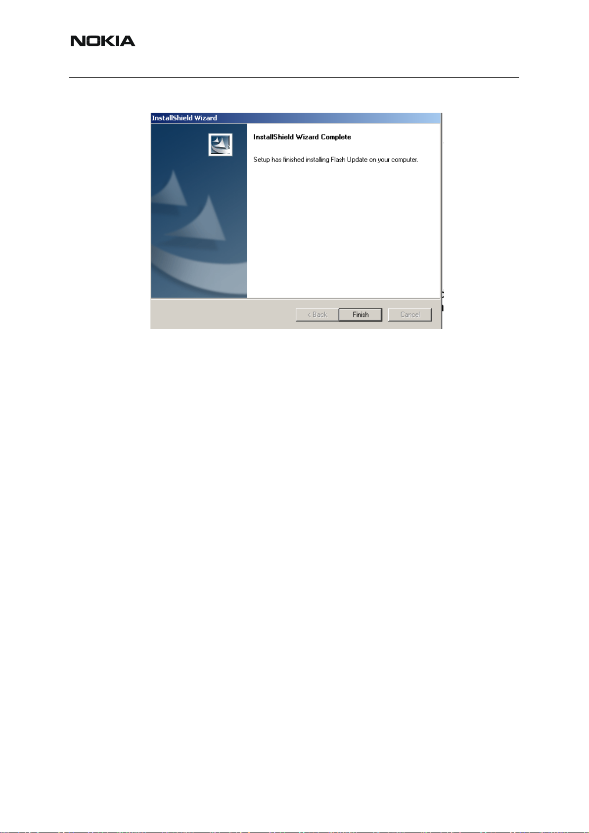
If the operating system does not require rebooting (Windows 2000, XP) the PC components are registered right away.
Click "Finish" to finalize. Phoenix is ready for use.
12 COMPANY CONFIDENTIAL ISSUE 1 09/2004
Copyright © 2004 Nokia. All Rights Reserved.
Page 13
RH-59/60
Nokia Customer Care
If the operating system used requires restarting your computer ( Windows 98, SE, ME )
the Install Shield Wizard will tell you about it. Select "Yes..." to reboot the PC immediatelly and
"No..." to reboot the PC manually afterwards.
After the reboot components are registered and Phoenix is ready for use. Note that Phoenix
doesn't work, if components are not registered.
Now the installation of Phoenix Service SW is ready and it can be used after :
Installing Phone model specific Phone Data Package for Phoenix
ISSUE 1 09/2004 COMPANY CONFIDENTIAL 13
Copyright © 2004 Nokia. All Rights Reserved.
Page 14
Nokia Customer Care
Configuring users and connections
FLS-4S can be used right away
FPS-8* can be used after updating Flash Update Package files to it
If reboot is not needed components are registered after copying them.
If restarting of your computer is not needed, Click "Finish" to exit the setup.
Phoenix is now ready for use.
Now the installation of Phoenix Service SW is ready and it can be used after:
RH-59/60
• Installing Phone model specific Phone Data Package for Phoenix
• Configuring the connections
• Updating the Flash Update Package files used with FPS-8* and FLS-4S* tools
14 COMPANY CONFIDENTIAL ISSUE 1 09/2004
Copyright © 2004 Nokia. All Rights Reserved.
Page 15
RH-59/60
Nokia Customer Care
■ Update installation of Phoenix
If you already have the Phoenix Service SW installed on your computer, sooner or later there
will be need to update it when new versions are released.
Always use the latest available versions of both the Phoenix Service SW and the Phone Specific Data Package . Instructions can be found in phone model specific Technical Bulletins and
Phone Datapackage readme.txt files ( shown during installation).
To update the Phoenix you need to take exactly the same steps as when installing it for the first
time.
• Download the installation package to your computer hard disk
• Close all other programs
• Use “Add/Remove Program” in “control panel” to remove old Phoenix. (Recommended).
• Run the application file produced in wk 33, 2004 or higher version (e.g.
phoenix_service_sw_a13_2004_08_5_42.exe)
• Newer version of Phoenix will be installed.
• Driver versions are checked and updated if necessary
When you update the Phoenix from old to new version (e.g. update from 2003_9_2_3 to
2003_33_5_22), the update will take place automatically without uninstallation
f you try to update the Phoenix with the same version that you already have ( e.g.
a10_2003_33_5_22 to a10_2003_33_5_22 ) you are asked if you want to unist all the version
of Phoenix you have on your PC.
In this case you can choose between total uninstallation and repair just like whan you choose
to uninstall Phoenix service software from the Windows control panel.
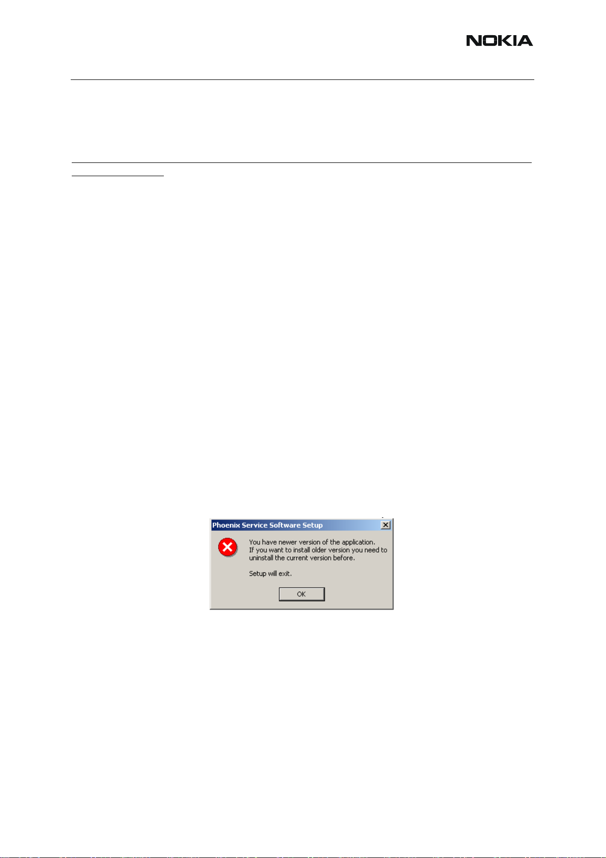
If you try to install an older version (e.g. downgrade from a11_2003_41_1_24 to
a10_2003_33_5_22 installation will be interrupted.
Always follow the instructions on the screen.
ISSUE 1 09/2004 COMPANY CONFIDENTIAL 15
Copyright © 2004 Nokia. All Rights Reserved.
Page 16
RH-59/60
Nokia Customer Care
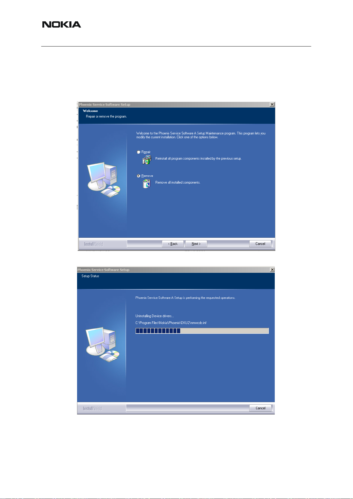
■ How to uninstall Phoenix
Uninstallation can be done manually from Windows Control Panel - Add / Remove Programs.
Choose “Phoenix Service Software” and click "Add/Remove".
Choose “Remove” to uninstall
Progress of the uninstallation is shown.
16 COMPANY CONFIDENTIAL ISSUE 1 09/2004
Copyright © 2004 Nokia. All Rights Reserved.
Page 17
RH-59/60
Nokia Customer Care
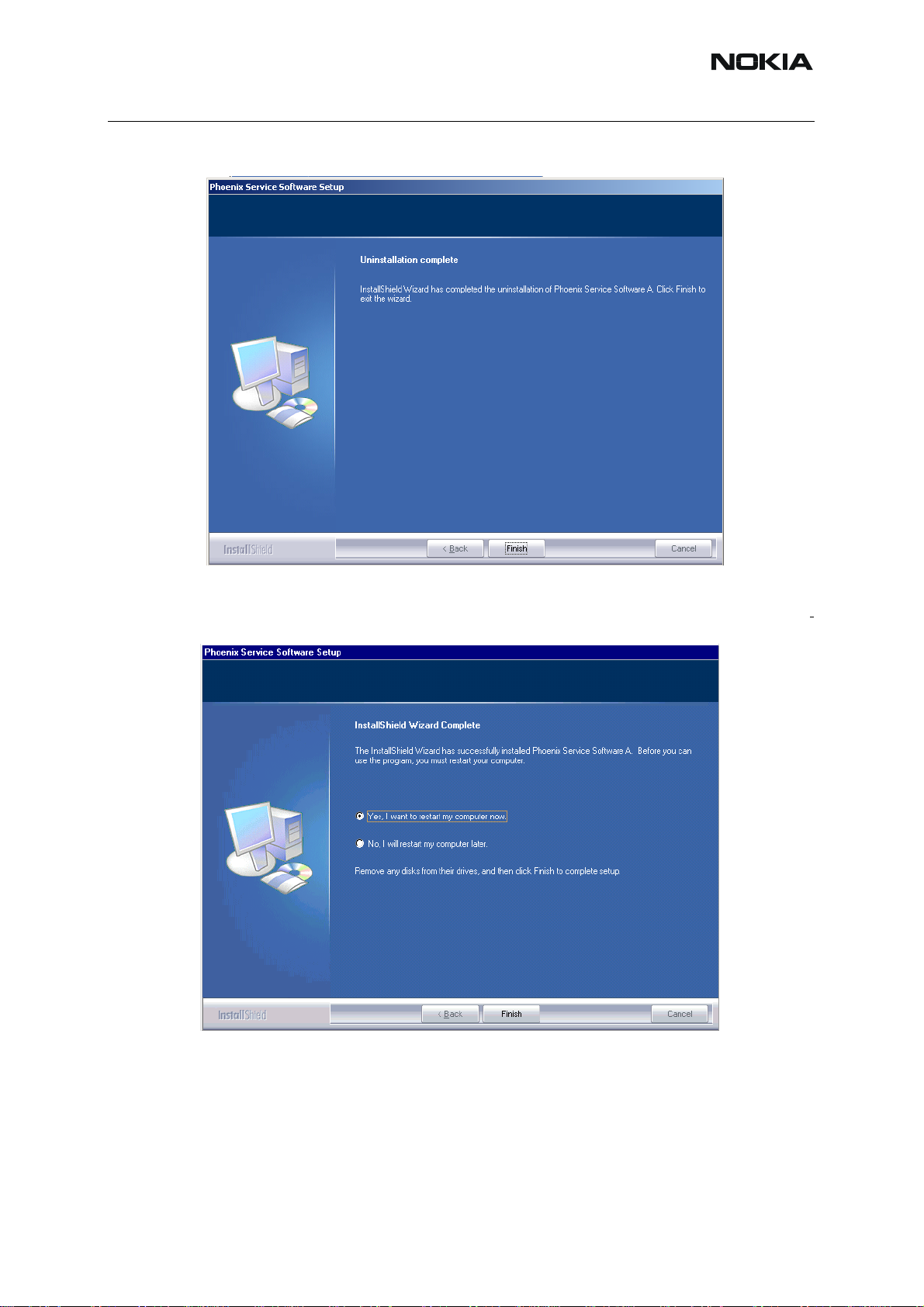
If the operating system does not require rebooting, select “Finish” to complete.
If the operating system used requires rebooting, Install Shield Wizard will tell you about it.
Select "Y es..." to reboot the PC imme diatelly and "No..." to reboot the PC manually afterwards.
ISSUE 1 09/2004 COMPANY CONFIDENTIAL 17
Copyright © 2004 Nokia. All Rights Reserved.
Page 18
RH-59/60
Nokia Customer Care
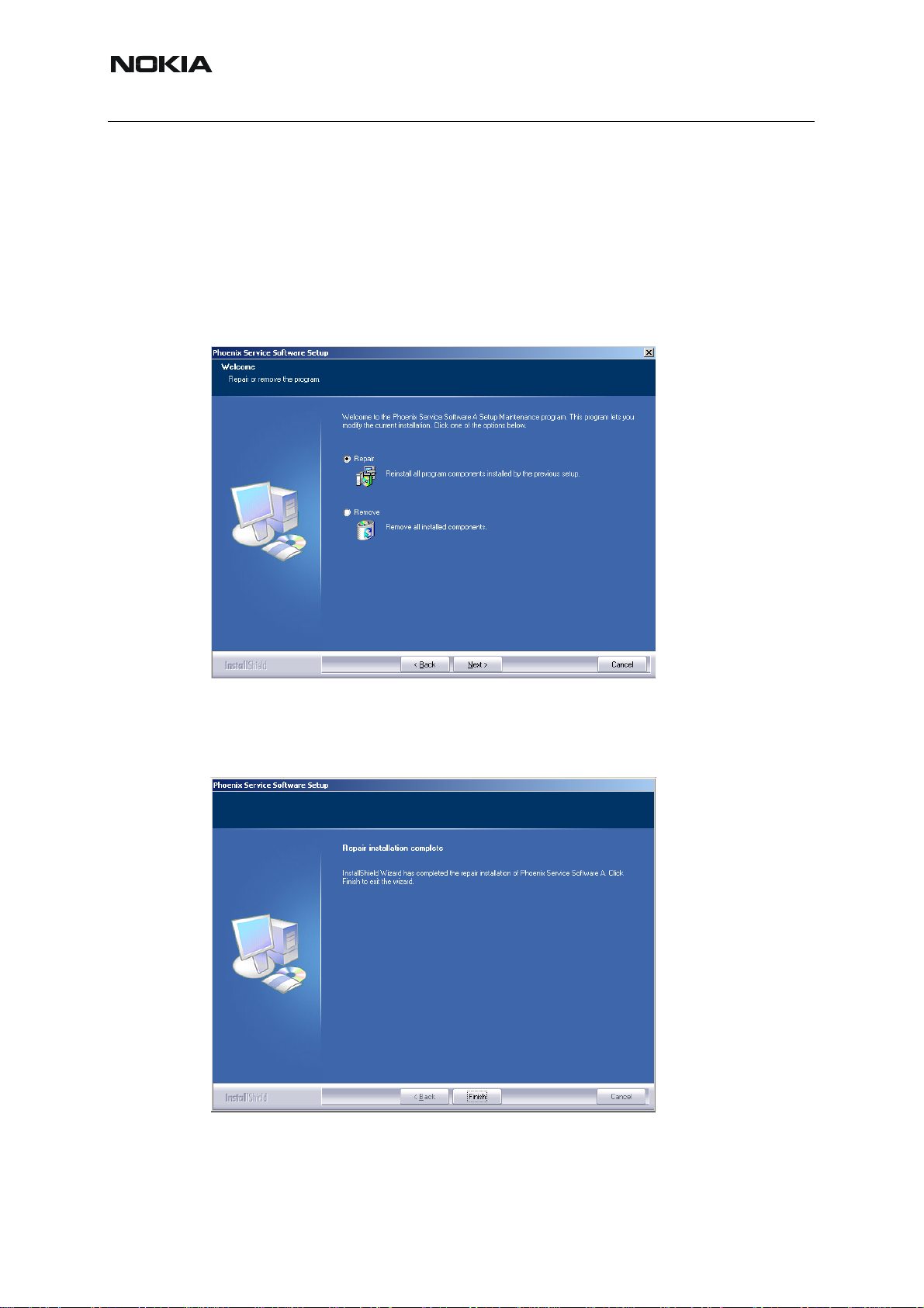
■ Repair
If you experience any problems with service software or suspect that files have been lost, you
can use the repair – function before completely reinstalling Phoenix. Note that the original installation package (application file produced in wk 33, 2004 or higher version e.g.
phoenix_service_sw_a13_2004_08_5_42.exe ) must be found on your PC when you run the
repair setup.
Run Windows Control Panel - Add / Remove Programs, choose “Phoenix Service Software”
and click "Add/Remove". In the following view choose “Repair”.
Phoenix will reinstall components and register them, procedure is the same as in update inst allation.
Choose “Finish” to complete.
18 COMPANY CONFIDENTIAL ISSUE 1 09/2004
Copyright © 2004 Nokia. All Rights Reserved.
Page 19

RH-59/60
Nokia Customer Care
Data Package for Phoenix (Product Specific)
■ Before installation
Product Data Package contains all product specific data to make the Phoenix Service Sof tware
and tools usable with a certain phone model.
It also includes the latest version of flash update package for FLS-4S* and FPS-8*
• Check that the Dongle is attached to the parallel port of your computer.
• Install Phoenix Service SW
• Download the installation package (eg RH-59/
60_dp_v_XX_XX_MCUSWx_xx.exe) to your computer (e.g. C:\TEMP)
• Close all other programs
• Use “Add/Remove Program” in “control panel” to remove old data package of
RH59/60
• Run the application file (eg
instructions on the screen
Please note that very often the Phoenix Service SW and t he Phone Specific Data Package for
Phoenix come in pairs, meaning that certain version of Phoenix can only be used with certain
version of Data Package.
Always use the latest available versions of both. Instructions can be found in phone model specific Technical Bulletins and readme.txt – files of the data packages.
RH-59/60_dp_v_XX_XX_MCUSWx_xx.exe) and follow
ISSUE 1 09/2004 COMPANY CONFIDENTIAL 19
Copyright © 2004 Nokia. All Rights Reserved.
Page 20
RH-59/60
Nokia Customer Care
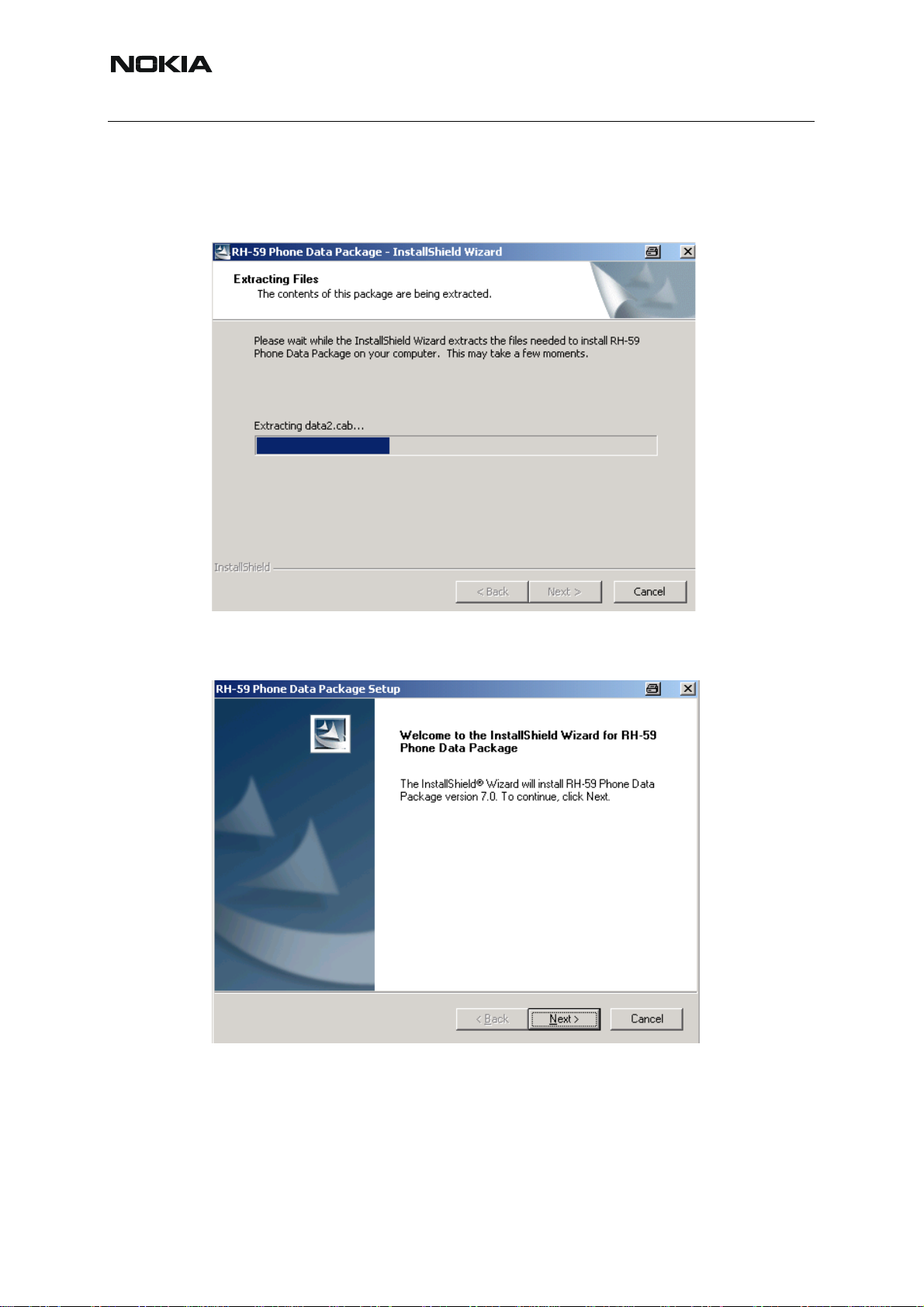
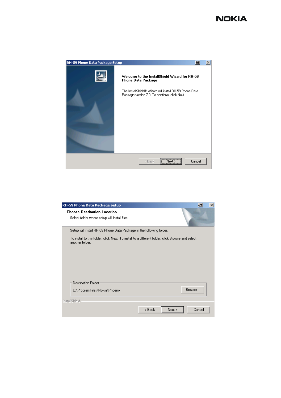
■ Installation of Phoenix Data Package (Product Specific)
Run the RH-59/60_dp_v_XX_XX_MCUSWx_xx.exe to start installation.
When you choose “Next” the files needed for installation will be extracted. Please wait…
Choose “Next” to continue.
From this view you can see the contents of the Data Package.
Read the text carefully.
20 COMPANY CONFIDENTIAL ISSUE 1 09/2004
Copyright © 2004 Nokia. All Rights Reserved.
Page 21
RH-59/60
Nokia Customer Care
There should be information about the Phoenix version needed with this data p ackage. Choose
“Next”.
Confirm location and choose “Next” to continue.
Install Shield checks where the Phoenix application is installed and the directory is shown.
Choose “Next” to continue.
ISSUE 1 09/2004 COMPANY CONFIDENTIAL 21
Copyright © 2004 Nokia. All Rights Reserved.
Page 22
Nokia Customer Care
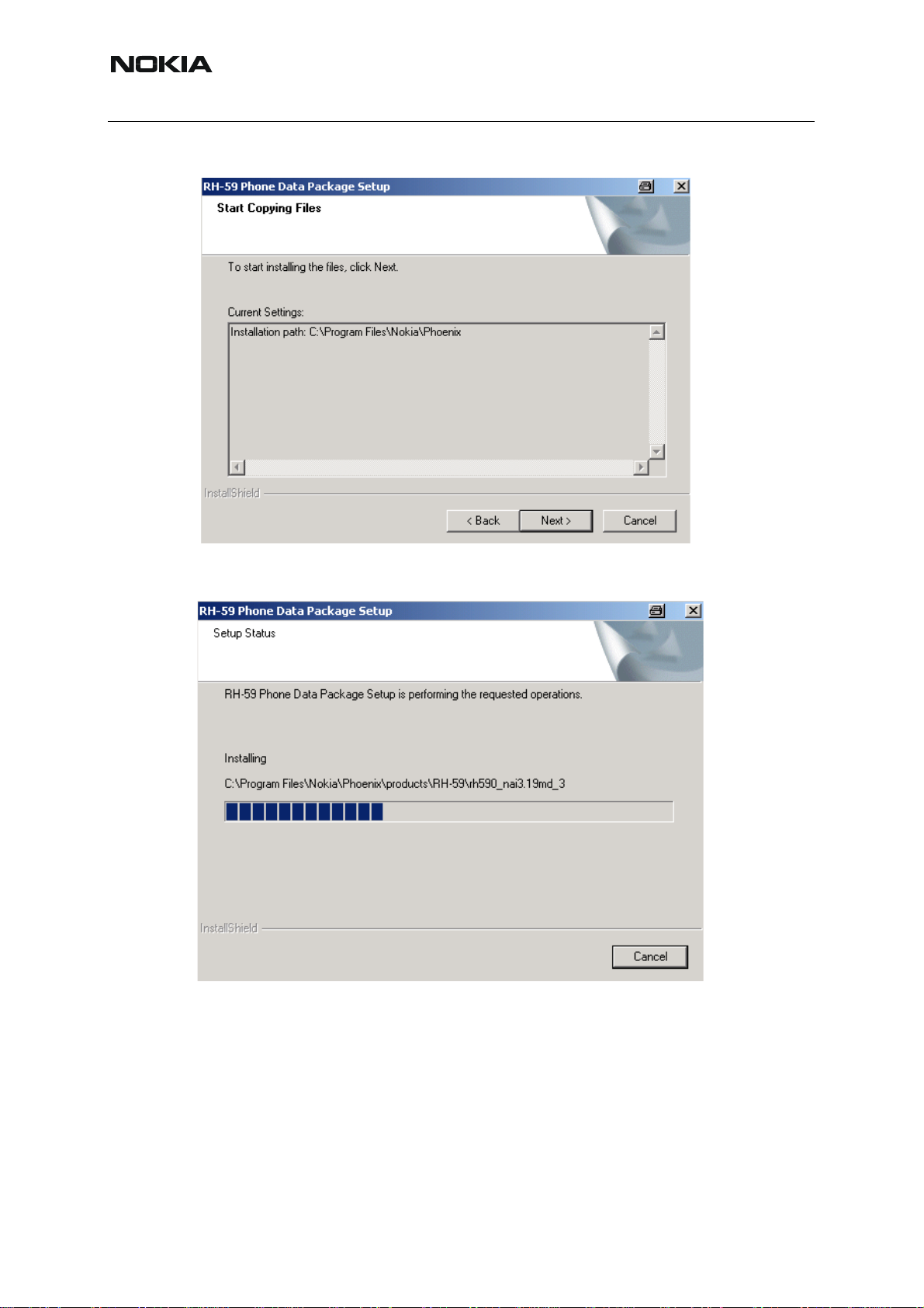
Choose “Next” to start copying the files.
RH-59/60
Phone model specific files will be installed.. please wait...
22 COMPANY CONFIDENTIAL ISSUE 1 09/2004
Copyright © 2004 Nokia. All Rights Reserved.
Page 23
RH-59/60
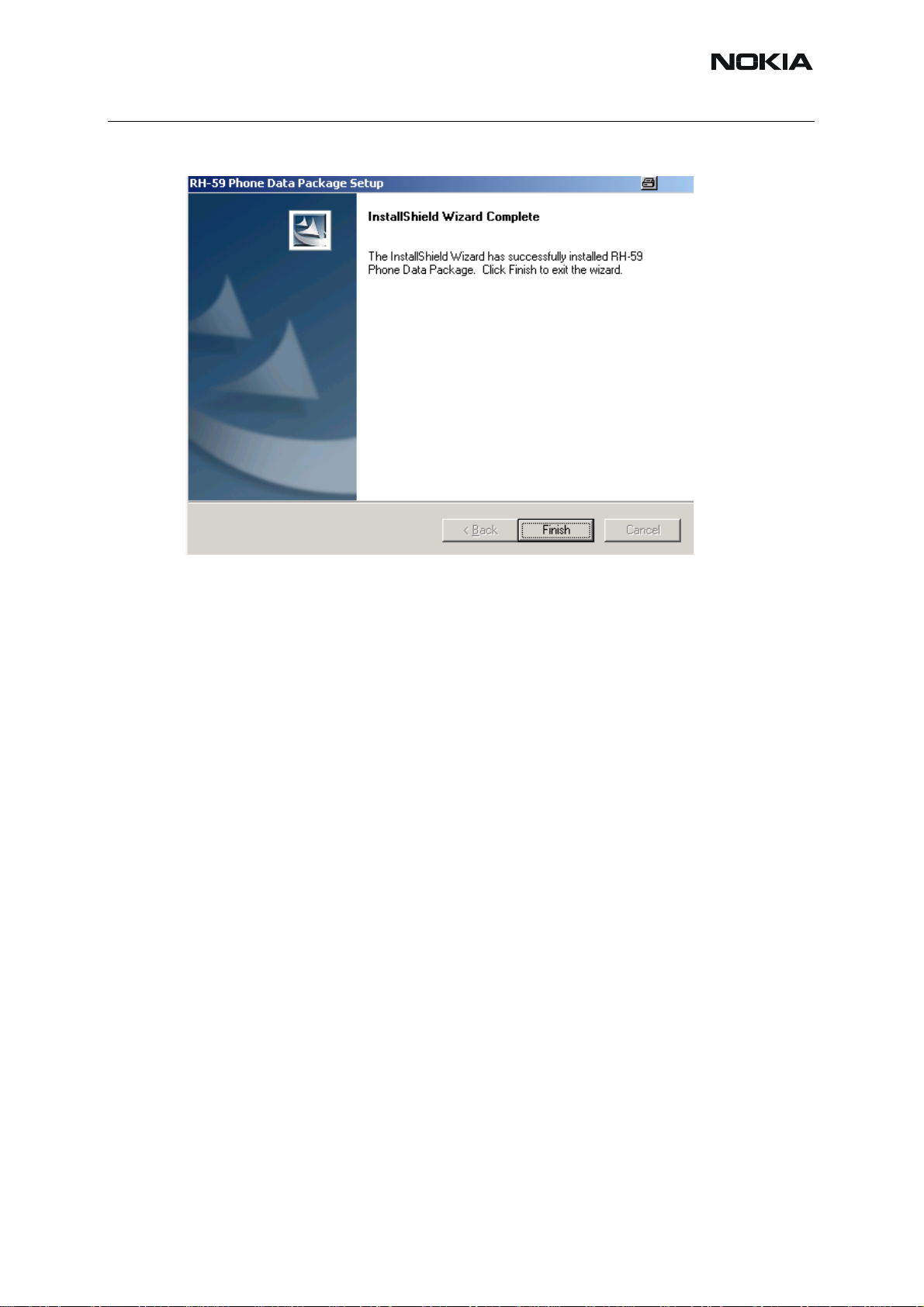
Choose “Finish” to complete installation.
Nokia Customer Care
You now have all phone model specific files installed in your Phoenix Service SW.
Now Phoenix can be used to for example flash phones and print type labels after :
• Configuring users
• Managing connections
• FLS-4S can be used right away
• FPS-8* can be used after updating Flash Update Package files to it
ISSUE 1 09/2004 COMPANY CONFIDENTIAL 23
Copyright © 2004 Nokia. All Rights Reserved.
Page 24
RH-59/60
Nokia Customer Care
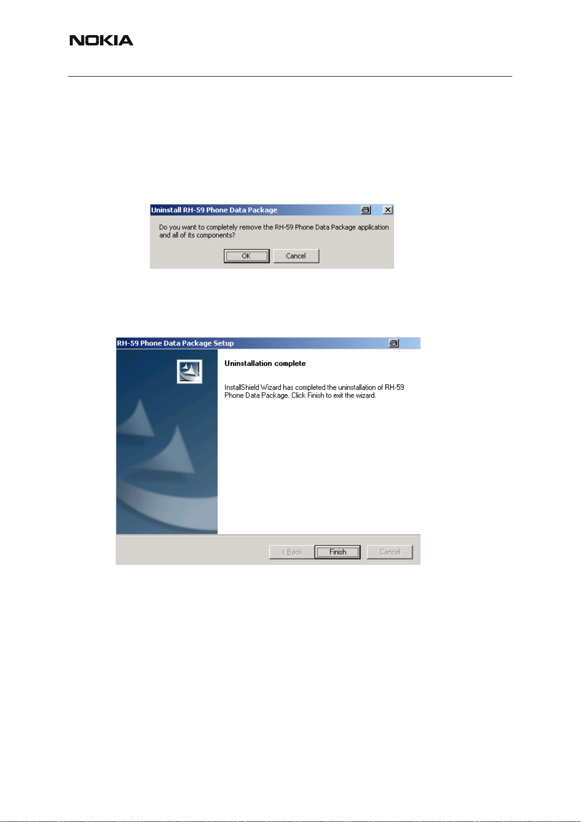
■ How to uninstall Data Package
Uninstallation can also be done manually from Windows Control Panel / Add / Remove Programs/ “RH-59/60 Phone Data Package”.
If you try to install the same version of Phoenix Data Package that you already have, you are
asked if you want to uninstall the version you have on your PC.
Answer “OK” to uninstall, “Cancel” if you don’t wa nt to uninstall. Older versions of data p ackages do not need to be uninstalled.
Older versions of data packages don´t need to be uninstalled unless instructions to do so are
given in the readme.txt of the data package and bulletin s concerning the release. Please read
all related documents carefully.
Once the previously installed Data package is uninstalled, choose “Finish”.
Run the RH-59/60_dp_v_XX_XX_MCUSWx_xx.exe again to continue inst allation from the beginning.
24 COMPANY CONFIDENTIAL ISSUE 1 09/2004
Copyright © 2004 Nokia. All Rights Reserved.
Page 25
RH-59/60
Nokia Customer Care
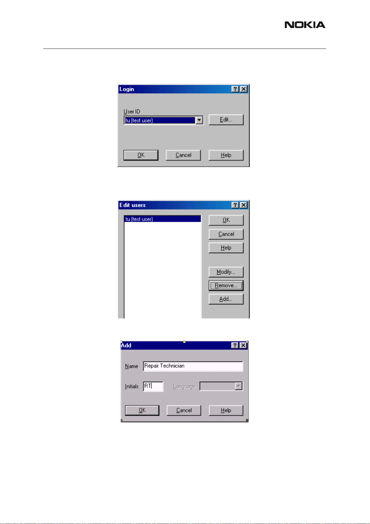
■ How to configure users
St art Phoenix Service SW and Login. To add new user choose “Edit”. If user ID is already co n-
figured, choose your own user ID from the list and choose “OK”
Choose “Add ” to continue.
Type in your name and Initials to fields and choose “OK”
ISSUE 1 09/2004 COMPANY CONFIDENTIAL 25
Copyright © 2004 Nokia. All Rights Reserved.
Page 26
Nokia Customer Care
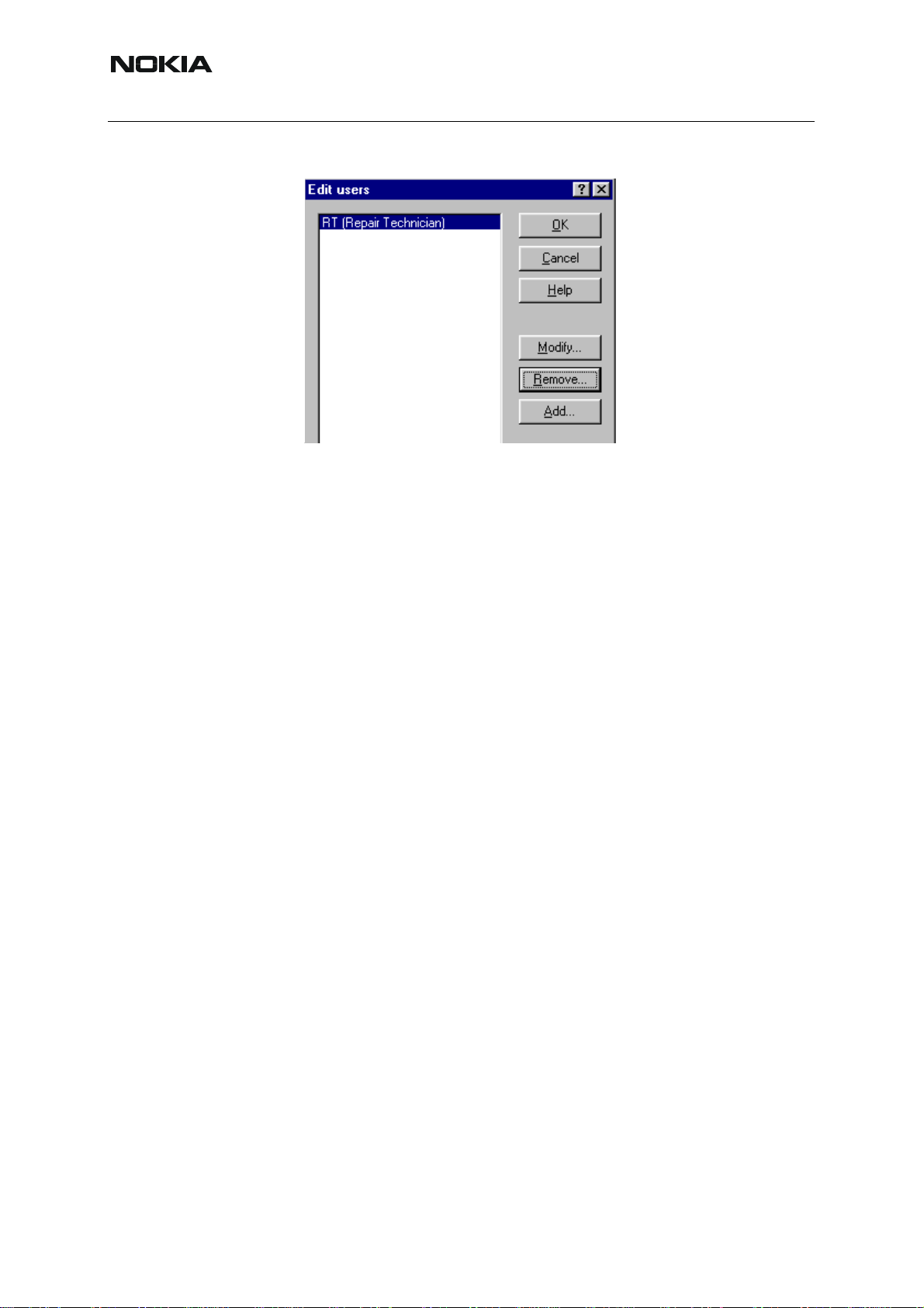
User has now been created, choose “OK”
You are now able to login with this username, choose “OK”
RH-59/60
26 COMPANY CONFIDENTIAL ISSUE 1 09/2004
Copyright © 2004 Nokia. All Rights Reserved.
Page 27
RH-59/60
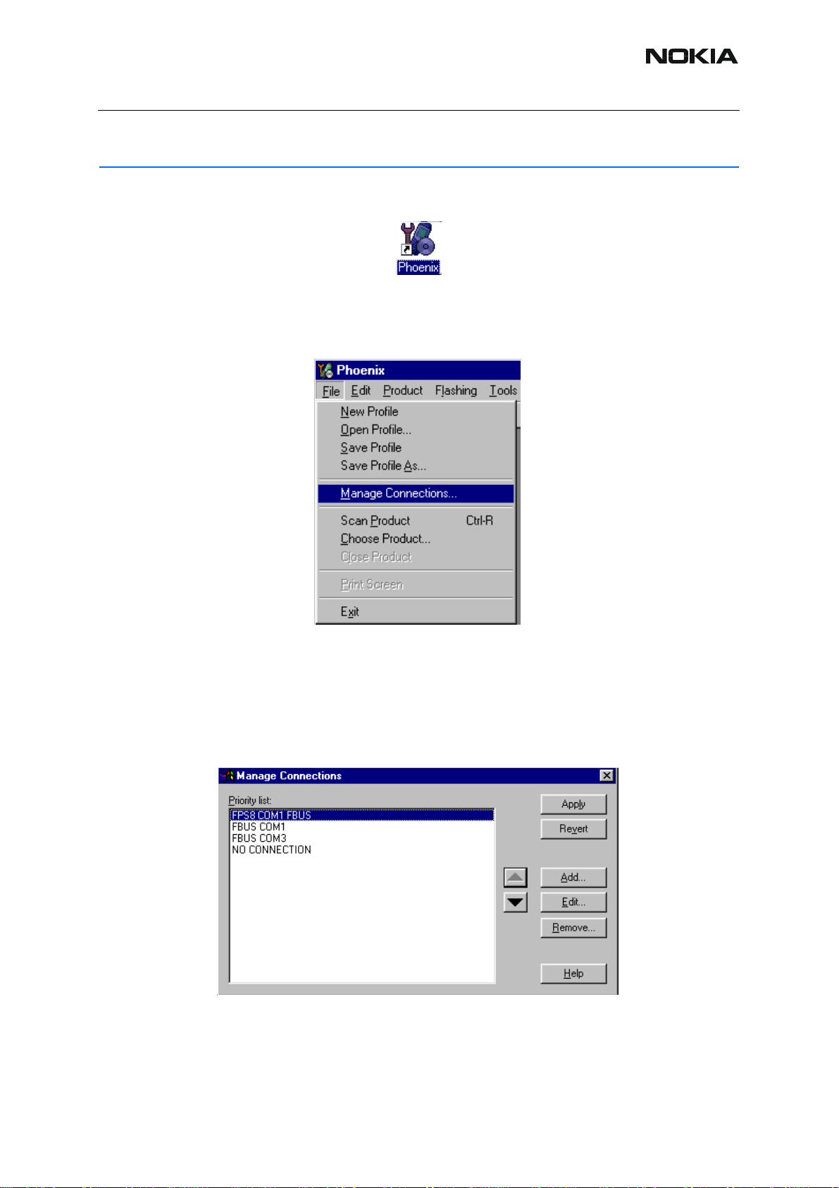
How to Manage Connections
Start Phoenix Service SW and Login.
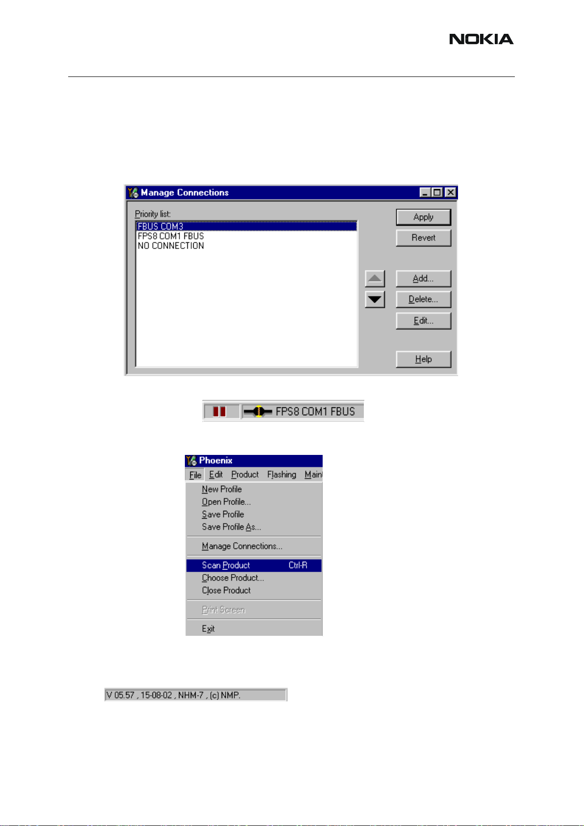
Choose “Manage Connections” From “File” – Menu
Nokia Customer Care
Existing connections can be selected , edited, deleted and new ones created by using this dialog.
A connection can be created either manually or by using a Connection Wizard.
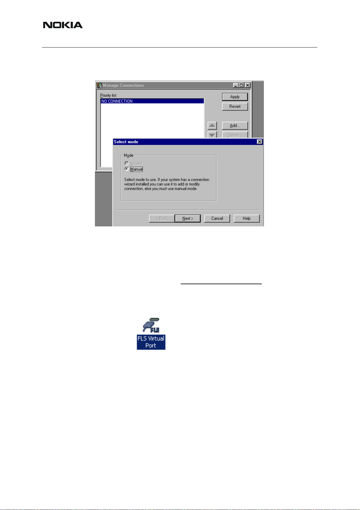
To add new connection, choose “Add” and select if you want to create it manually or by using
the Wizard.
Choose “Next” to continue.
ISSUE 1 09/2004 COMPANY CONFIDENTIAL 27
Copyright © 2004 Nokia. All Rights Reserved.
Page 28
Nokia Customer Care
In the next dialogs you will be asked to select some settings for the connection.
RH-59/60
Manual Settings
A) For FLS-4S POS Flash Device choose following connection settings:
Media: FBUS
COM Port: Virtual COM Port used by FLS-4S. Please check this always!
(To check please go to Windows / Control Panel / FLS Virtual Port / Configuration)
(To check please go to Windows / Control Panel / FLS Virtual Port / Configuration)
B) For FPS-8 Flash Prommer choose following connection settings:
Media: FPS-8
Port Num: COM Port where FPS-8 is connected
COMBOX_DEF_MEDIA: FBUS
Choose “Finish” to complete.
28 COMPANY CONFIDENTIAL ISSUE 1 09/2004
Copyright © 2004 Nokia. All Rights Reserved.
Page 29
RH-59/60
Nokia Customer Care
If you use the Wizard, connect the tools and a phone to your PC and the wizard will automatically try to configure the correct connection.
Activate the connection you want to use by clicking it and use up/down arrows to move it on
top of the list. Choose “Apply”.
The connection is now selected and can be used after closing the “Manage Connections” window.
Selected connection will be shown on the right hand bottom corner of the screen.
To use the selected connection, connect the phone to Phoenix with correct service tools, make
sure that it is switched on and select “Scan Product”.
When the Product is found, Phoenix will load product support and when everything is ready,
name of the loaded product support module and its version will be shown on the bottom of the
screen.
ISSUE 1 09/2004 COMPANY CONFIDENTIAL 29
Copyright © 2004 Nokia. All Rights Reserved.
Page 30

Nokia Customer Care
RH-59/60
[This page left intentionally blank]
30 COMPANY CONFIDENTIAL ISSUE 1 09/2004
Copyright © 2004 Nokia. All Rights Reserved.
Page 31

RH-59/60
Nokia Customer Care
How to Update Flash Support Files for FPS-8* and FLS-4S*
■ Before installation
Install Phoenix Service SW
Install phone model Specific Datapackage for Phoenix
The flash support files are delivered in the same installation package with Phoenix data pack-
ages or newer Phoenix packages beginning from September 2003.
Normally it is enough to install the Phoenix and phone dat a package only because the Phoenix
installarion always includes the latest flash update package files for FLS-4S / FPS-8*.
Separate installation packag e is for flash support files is available, an d the files can be updated
according to this instruction if updates appear between Phoenix / data package releases.
■ Installing the flash support files
If you are not using separate installation package, you can skip this section and continue from
yhe next section after installing a new Phone Data package.
Start by double clicking flash_update_03_12_000.exe . Installation begins.
IIf the same version of Flash Update package already exists, and you want to reinstall them,
the prevous package is first uninstalled. Restart installation again after that.
ISSUE 1 09/2004 COMPANY CONFIDENTIAL 31
Copyright © 2004 Nokia. All Rights Reserved.
Page 32

RH-59/60
Nokia Customer Care
.
If you try to downgrade the existing version to older ones, the setup will be aborted. If yoy really
want to downgrade, unistall newer files manually from Control Pan el and then re run the installation again.
If an older version exists on your PC and it needs to be updated, Choose “Next” to continue
installation.
It is highly recommended to install the files to the default destination folder C:\Program
Files\Nokia\Phoenix.
32 COMPANY CONFIDENTIAL ISSUE 1 09/2004
Copyright © 2004 Nokia. All Rights Reserved.
Page 33

RH-59/60
Nokia Customer Care
Choose “Next” to continue. You may choose another location by selecting “Browse” (not recommended).
Installation continues…
Choose “Finish” to complete procedure.
• FLS-4S can be used right after Flash Update Package is installed.
ISSUE 1 09/2004 COMPANY CONFIDENTIAL 33
Copyright © 2004 Nokia. All Rights Reserved.
Page 34
Nokia Customer Care
• FPS-8* must be updated by using Phoenix!
RH-59/60
34 COMPANY CONFIDENTIAL ISSUE 1 09/2004
Copyright © 2004 Nokia. All Rights Reserved.
Page 35

RH-59/60
Nokia Customer Care
■ How to update the FPS-8* Flash Prommer SW
Start Phoenix Service Software
Select”FPS-8 / FPS-8C maintenance” from”Flashing” menu.
When new FPS-8 flash update package is installed to computer you will b e asked to update the
files to your FPS-8 Prommer. Select”Yes” to update files..
0200
Update procedure takes a couple of minutes, please wait until you are notified that updat e has
been successfull. Choose “OK” and close “FPS8 Maintenance” – UI. .
ISSUE 1 09/2004 COMPANY CONFIDENTIAL 35
Copyright © 2004 Nokia. All Rights Reserved.
Page 36

Nokia Customer Care
View after successful prommer software update
RH-59/60
FPS-8 sw can also be updated by pressing”Update” button and selecting appropriate
fps8upd.ini file under C:\Program Files\Nokia\Phoenix\Flash - directory
All files can be loaded separately to FPS-8. To do this, just press right mouse button in Flash
box files” window and select file type to be loaded.
More information and help can be found from the “Help” dialog.
36 COMPANY CONFIDENTIAL ISSUE 1 09/2004
Copyright © 2004 Nokia. All Rights Reserved.
Page 37

RH-59/60
Nokia Customer Care
FPS-8 Activation and Deactivation
• Before the FPS-8 can be successfully used for phone programming, it must be
first activated.
• If there is a need to send FPS-8 box to somewhere e.g. for repair, box must be
first deactivated.
■ Activation
Before FPS-8 can be successfully used for phone programming, it must be first activated.
Fill in first “FPS-8 activation request” sheet, in the FPS-8 sales package and follow the instruc-
tions in the sheet.
When activation file is received (e.g. 00000.in), copy it to C:\ProgramFiles\Nokia\Phoe-
nix\BoxActivation - Directory on your computer
(This directory is created when Phoenix is installed).
Start Phoenix Service Software.
Select ”FPS-8 / FPS-8C maintenance” from ”Flashing” menu.
Select “Activate” from the “FPS8/8C Maintenance” – UI.
ISSUE 1 09/2004 COMPANY CONFIDENTIAL 37
Copyright © 2004 Nokia. All Rights Reserved.
Page 38

RH-59/60
Nokia Customer Care
The activation file you saved to C:\ProgramFiles\Nokia\Phoenix\BoxActivation - directory will
be shown (e.g. 00000.in), check that it is correct.
Box will be activated when you choose “Open”.
Turn FPS-8 power off and on to complete activation.
38 COMPANY CONFIDENTIAL ISSUE 1 09/2004
Copyright © 2004 Nokia. All Rights Reserved.
Page 39
RH-59/60
■ Deactivation
Start Phoenix Service Software.
Select ”FPS-8 / FPS-8C maintenance” from ”Flashing” menu.
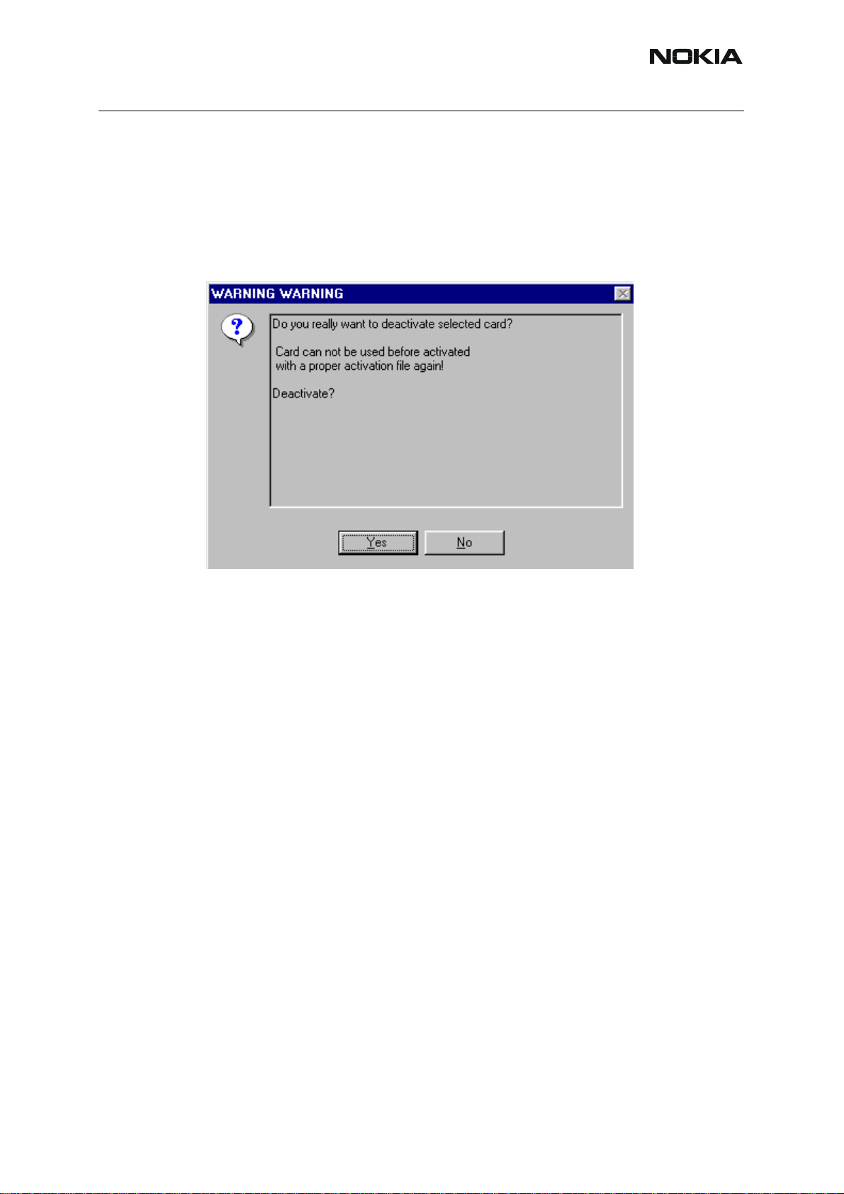
Select “Deactivate” from the “FPS8/8C Maintenance” – UI.
Confirm Deactivation by choosing “Yes”, Box will be deactivated.
Nokia Customer Care
Turn FPS-8 power off and on to complete deactivation.
ISSUE 1 09/2004 COMPANY CONFIDENTIAL 39
Copyright © 2004 Nokia. All Rights Reserved.
Page 40

RH-59/60
Nokia Customer Care
JBV-1 Docking Station SW
The JBV-1 Docking Station is a common tool for all DCT-4 generation products. In order to
make the JBV -1 usable with different phone models, a phone specific Docking S t ation Adapter
is used for different service functions.
The JBV-1 Docking Station contains Software (Firmware) which can be updated.
You need the following equipment to be able to update JBV-1 software:
• PC with USB connection
• Operating System supporting USB (Not Win 95 or NT)
• USB Cable (Can be purchased from shops or suppliers providing PC hardware
and accessories)
• JBV-1 Docking Station
• External Power Supply 11-16V
■ Before installation
• Download Jbv1_update.zip – file to your computer (e.g. C:\TEMP) from your
download web site.
• Close all other programs
• Follow instructions on the screen
40 COMPANY CONFIDENTIAL ISSUE 1 09/2004
Copyright © 2004 Nokia. All Rights Reserved.
Page 41

RH-59/60
Nokia Customer Care
■ Installing SW needed for the JBV-1 SW update
Note: DO NOT CONNECT THE USB CABLE / JBV-1 TO YOUR COMPUTER YET!
Run Jbv1_update.zip file and start SW Installation by double clicking Setup.exe.
Files needed for JBV-1 Package setup Program will be extracted.
Installation begins, please read the information shown and Choose “Next” to continue.
ISSUE 1 09/2004 COMPANY CONFIDENTIAL 41
Copyright © 2004 Nokia. All Rights Reserved.
Page 42
RH-59/60
Nokia Customer Care
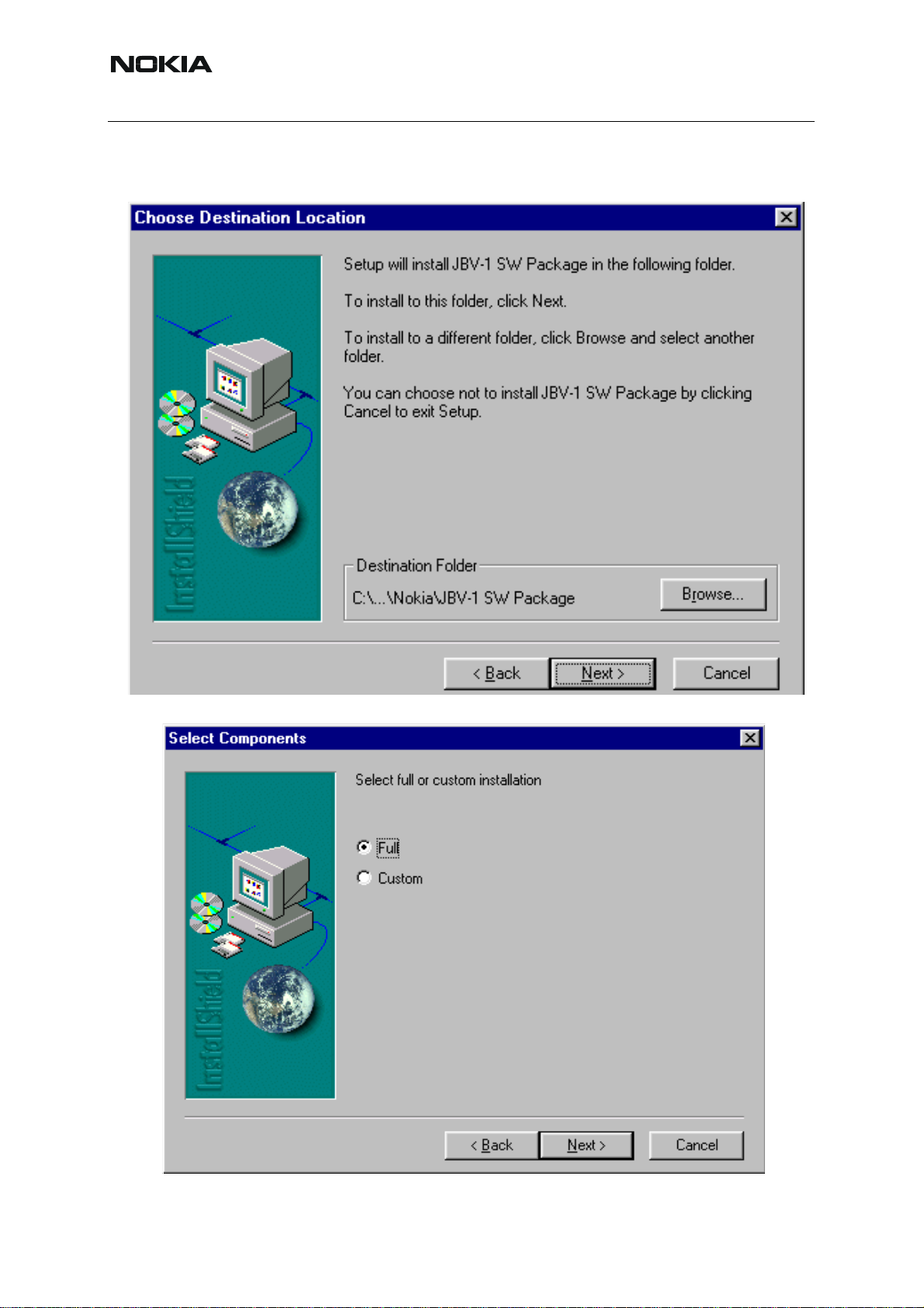
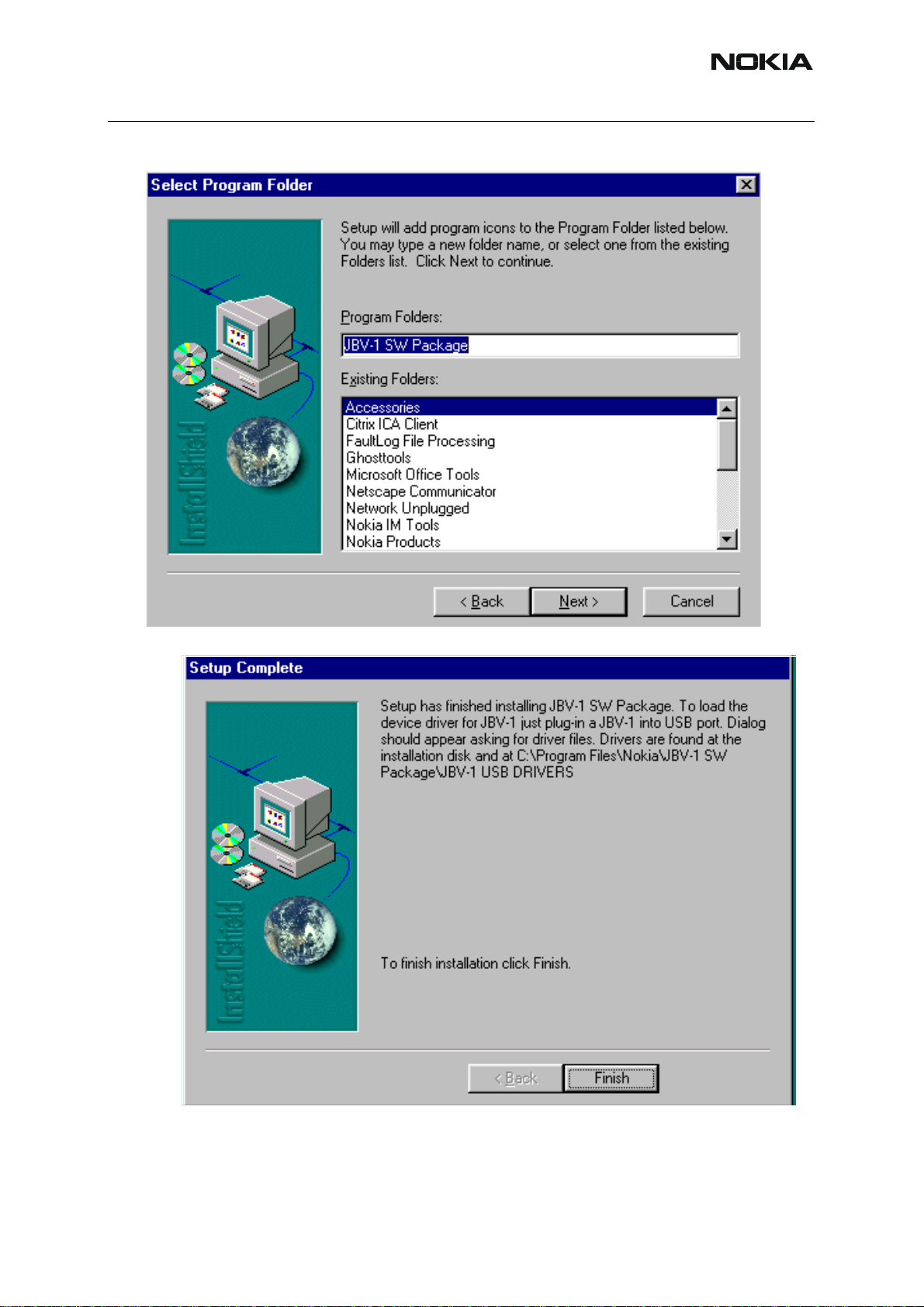
Use suggested destination folder where JBV -1 SW Package will be installed and choose “Next”
to continue.
Select “Full” Installation and choose “Next” to continue
42 COMPANY CONFIDENTIAL ISSUE 1 09/2004
Copyright © 2004 Nokia. All Rights Reserved.
Page 43
RH-59/60
Nokia Customer Care
Program Folder will be created. Choose “Next” to continue, Software files will be installed.
After successful installation, choose “Finish” to complete.
NOW YOU CAN CONNECT THE USB CABLE / JBV-1 TO YOUR COMPUTER!
Connect power to JBV -1 (1 1-16V DC) from external power supp ly , then connect USB Cable be-
tween JBV-1 USB connector and PC.
ISSUE 1 09/2004 COMPANY CONFIDENTIAL 43
Copyright © 2004 Nokia. All Rights Reserved.
Page 44
RH-59/60
Nokia Customer Care
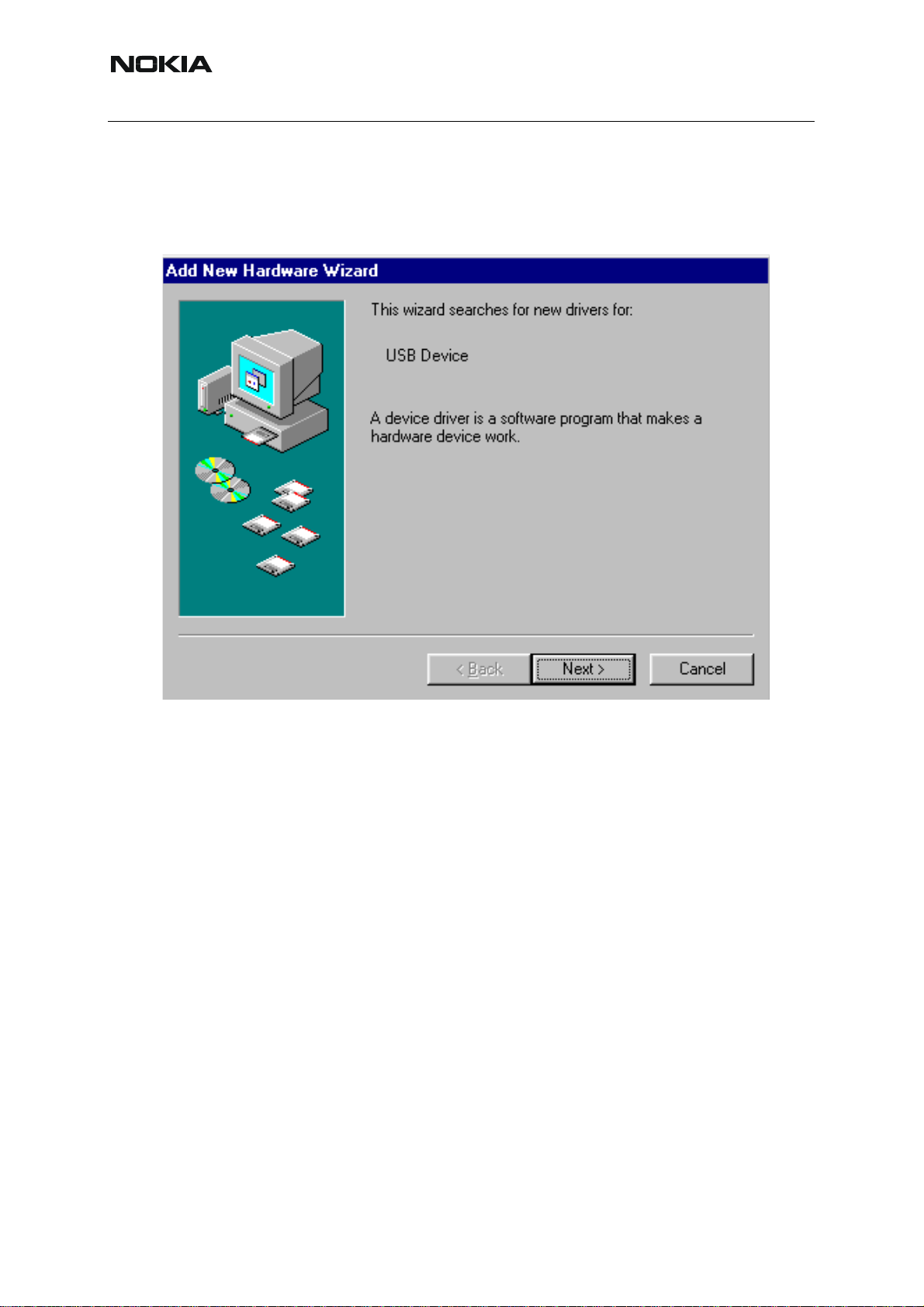
Windows will detect connected USB cable and detect drivers for new HW.
Follow the instructions and allow Windows to search and install the best drivers available. After
this procedure the actual JBV-1 SW update can begin.
44 COMPANY CONFIDENTIAL ISSUE 1 09/2004
Copyright © 2004 Nokia. All Rights Reserved.
Page 45

RH-59/60
Nokia Customer Care
■ Updating the JBV-1 Docking Station software
The next step is to install or update the JBV-1 USB drivers which are delivered with the JBV-1
SW installation package. They can be found in folder:
C:\Program Files\Nokia\ JBV-1 Firmware Update\JBV-1USB driver
If there is no previously installed JBV -1 Fi rmware update package inst alled on your computer,
Windows will detect connected USB cable and detect drivers for new HW . Y ou will be prompted
about this, please follow the instructions and allow Windows to search and install the best Drivers available.
If there is a previously installed JBV-1 Firmware update package ( v 17 or older) on your computer, please update the JBV-1 USB Driver. Please see the readme.txt – file under
C:\Program Files\Nokia\ JBV -1 Firmware Update\JBV -1USB driver – f older for in struction s on
how to update the JBV-1 USB Driver.
After you have installed or updated the JBV-1 USB driver, the actual JBV -1 SW update can begin.
Go to folder C:\Program Files\Nokia\JBV-1 Firmware Update\JBV-1 Firmware Up date and start
JBV-1 Update SW by double clicking fwup.exe.
JBV-1 Firmware update starts and shows current satus of the JBV-1 connected.
If firmware version read from your JBV -1 is not the latest one available ( v . 17 or older) , it needs
to be updated to version 18 by choosing “Update Firmware”.
”.
To update your JBV-1 to new version 18 choose file JBV1v18.CDE and “Open”
Please wait, it takes a while until you can hear a “click” from the JBV-1.
The older sw file JBV1v17.CDE is visible in this view only if the previous JBV-1 SW package
has been installed on your computer.
ISSUE 1 09/2004 COMPANY CONFIDENTIAL 45
Copyright © 2004 Nokia. All Rights Reserved.
Page 46

Nokia Customer Care
RH-59/60
[This page left intentionally blank]
46 COMPANY CONFIDENTIAL ISSUE 1 09/2004
Copyright © 2004 Nokia. All Rights Reserved.
Page 47

RH-59/60
Nokia Customer Care
Service Tool Concept For Baseband Tuning Operations
EM calibrations should be carried out in JBV-1 Docking Station equipped with DA-35 Docking
St a t ion Ad apter.
Note: RF tunings must be carried out in MJ-15 module jig, JBV-1.
Power to JBV-1 should be supplied from an external DC power supply, not
JBV-1 input voltages:
Maximum +16 VDC
Nominal input for RF tunings is +12 V DC.
FPS-8 prommer.
ISSUE 1 09/2004 COMPANY CONFIDENTIAL 47
Copyright © 2004 Nokia. All Rights Reserved.
Page 48

Nokia Customer Care
■ Service concept for baseband tunings
RH-59/60
7
8
4
3
2
1
Table 1:
6
5
Item Accessory type Service Accessory Product code
1 JBV-1 Docking Station 0770298
2 DA-35 Docking Station
0770674
adapter
3 CA-5S DC-DC Cable 0730283
5 PCS-1 DC power cable 0730012
6 DAU-9S Service FBUS cable 0730108
7 PKD-1 Software protection
0750018
key
8 Service SW CD-ROM
48 COMPANY CONFIDENTIAL ISSUE 1 09/2004
Copyright © 2004 Nokia. All Rights Reserved.
Page 49

RH-59/60
Nokia Customer Care
Baseband Tuning operations
■ Energy management tuning
External power supply needed.
Energy Management (EM) Calibration is used for calibrating Battery and Charger settings of
the phone.
Preparation for EM Calibration:
- Connect the DC Cable SCB-3 between JBV-1 and Vin of the Phone for Charger calibration.
- Connect 12…15 V from the Power Supply to JBV-1.
- NOTE! Check that the connection is F-BUS (does not work with M-BUS).
Select Tuning => Energy Management Calibration.
Energy Management values to be calibrated are checked.
Select “Read from Phone” to show the current values in the phone memory and to check that
the communication with the phone works.
ISSUE 1 09/2004 COMPANY CONFIDENTIAL 49
Copyright © 2004 Nokia. All Rights Reserved.
Page 50

Nokia Customer Care
Select “Calibrate” to run the selected calibrations.
RH-59/60
Limits for Energy Management Calibration:
Table 2:
Parameter Min. Max Note
ADC gain 25400 29000 VBatt, BSI, BTemp
DC offset -50 50 ADC voltage offset
BSI gain 970 1100 ADC BSI calibration gain
BTEMP gain 2075 2275 ADC BTEMP calibration
gain
VBAT gain 10000 11000 ADC VBATT Voltage gain
VBAT offset 2300 2900 ADC VBATT Voltage offset
scale
VCHAR 58000 62000 Charge voltage
ICHAR 4050 4800 charge current
If values shown are within limits select “Save To Phone” to save the values in the phone.
NOTE! Only the values of the checked tunings (Battery size, Battery Temperature etc.) are
saved.
Close the “Energy Management Calibration” – dialog to end tuning.
You must manually switch the phone on after exiting “Energy Management Calibration” – dia-
log.
50 COMPANY CONFIDENTIAL ISSUE 1 09/2004
Copyright © 2004 Nokia. All Rights Reserved.
Page 51

RH-59/60
Nokia Customer Care
■ LCD contrast tuning
Extra equipment not needed.
This function is used to calibrate the LCD Contrast.
Must be done when LCD module is changed and there is considerable difference in the con-
trast.
Select Testing => Display Tune
Move the sliders to reach good LCD contrast.
Close the ”Display tune” dialog to end tuning.
ISSUE 1 09/2004 COMPANY CONFIDENTIAL 51
Copyright © 2004 Nokia. All Rights Reserved.
Page 52

Nokia Customer Care
RH-59/60
[This page left intentionally blank]
52 COMPANY CONFIDENTIAL ISSUE 1 09/2004
Copyright © 2004 Nokia. All Rights Reserved.
Page 53

RH-59/60
Nokia Customer Care
Receiver Tuning: Quick Guide for Tuning With Phoenix
■ General remarks
RF tunings must be performed in the same order as shown in this document. The order of the
corresponding menu items in the Service SW may be different.
If baseband tunings are needed, they should be completed before the RF tunings.
Avoid unnecessary tuning – factory-tuning values are always the most accurate ones.
NOTE! RF tunings need to be done ONLY if any RF block component is replaced.
Screen shots described in this document may change as the service software is developed.
Kindly refer to the Phoenix help files, the phone model specific service manual and bulletins for
help.
ISSUE 1 09/2004 COMPANY CONFIDENTIAL 53
Copyright © 2004 Nokia. All Rights Reserved.
Page 54

Nokia Customer Care
Service Tool Concept for RF Tuning Operations
NOTE! RF tunings need to be done ONLY if any RF block component is replaced.
• All RF tuning operations must be carried out in the MJ-15 Module Jig!
RH-59/60
• Power to MJ-15 must be supplied from an external DC power supply, not
prommer
• MJ-15 input voltages:
Maximum + 5 VDC
Nominal input for RF tunings is +4.2 V DC
Minimum +3V DC
• Remember the cable attenuation when setting required RF levels
5
6
2
1
4
FPS-8
3
Figure 1:RF tuning setup
Table 1:
Item: Type: Service accessory:
Product
code:
1 MJ-15 Module jig 0770739
2 PCS-1 DC power cable 0730012
3 XRF-1 Modular cable 0730085
4 DAU-9S Service Mbus cable 0730108
5 PKD-1 Software protection key 0750018
6 CD-ROM Service SW
54 COMPANY CONFIDENTIAL ISSUE 1 09/2004
Copyright © 2004 Nokia. All Rights Reserved.
Page 55

RH-59/60
Nokia Customer Care
Autotuning
Autotune feature is designed to align product’s RF part easier and faster . By this autotune component the product is tuned automatically. The user only needs to press ‘Tune’ and the prod-
uct’s RF is tuned and results are shown to the user. Component controls all the needed RF
equipment (RF generator and TX measuring device) except voltage supplier.
NOTE! Automatic tuning is ALWAYS the primary tuning mode. Manual tuning is not recommended.
Following diagram describes how the Autotune component is located in the TSS architecture:
Figure 2:Autotune component in TSS architecture
Autotune is a pair of two different component s. One is User Interface and the other is Fu nctioNal. UI does not contain any functionality. MTI takes care of phonet messages.
The Autotune component can be found under Tuning menu:
Figure 3:Autotune menu in Phoenix
ISSUE 1 09/2004 COMPANY CONFIDENTIAL 55
Copyright © 2004 Nokia. All Rights Reserved.
Page 56

Nokia Customer Care
RH-59/60
Figure 4:Autotune menu - RX/TX menu
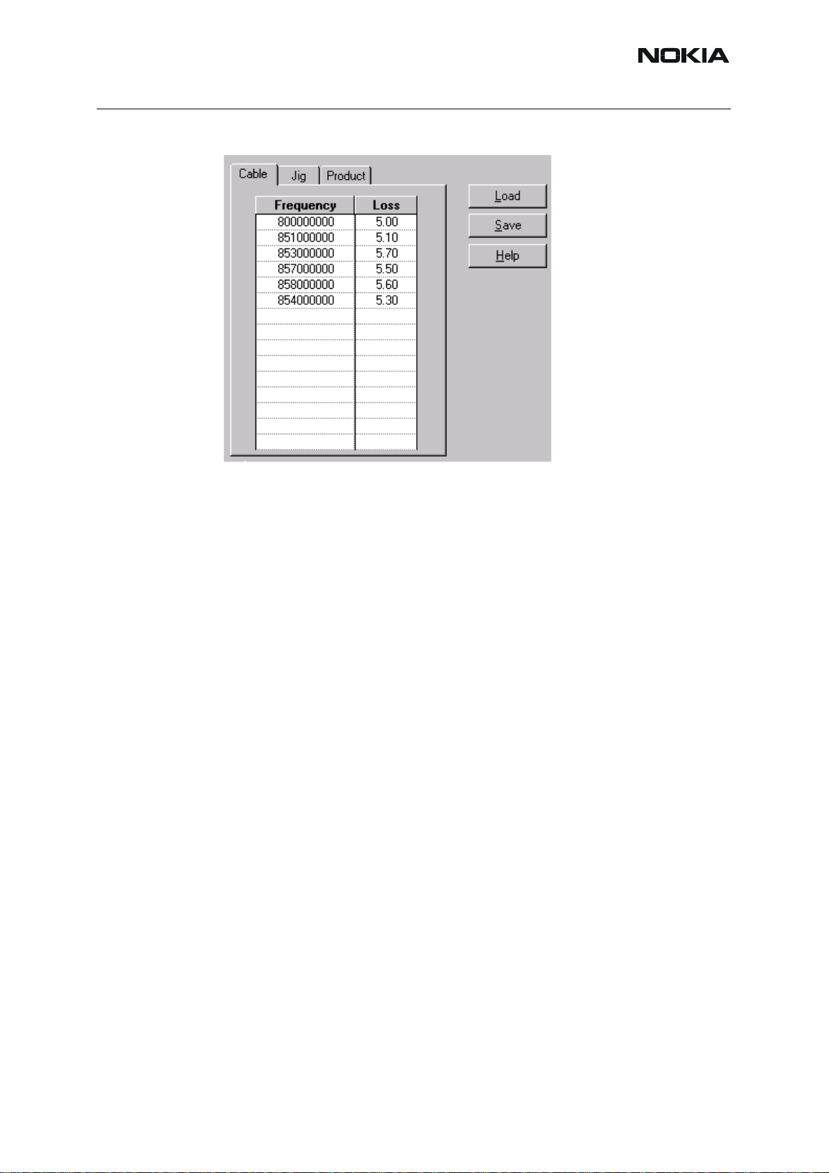
Set loss
Figure 5:Set loss menu
This is the component for saving RF-losses (of cables and jigs) to file. These loss values are
needed when you tune the phone with Phoenix (using Auto-Tune component). When you
measure the losses you have to be very careful, because these values aff ect directly how well
the phone is tuned.
NOTE! This component is only for Auto-Tune uses.
56 COMPANY CONFIDENTIAL ISSUE 1 09/2004
Copyright © 2004 Nokia. All Rights Reserved.
Page 57
RH-59/60
Nokia Customer Care
Figure 6:Loss values
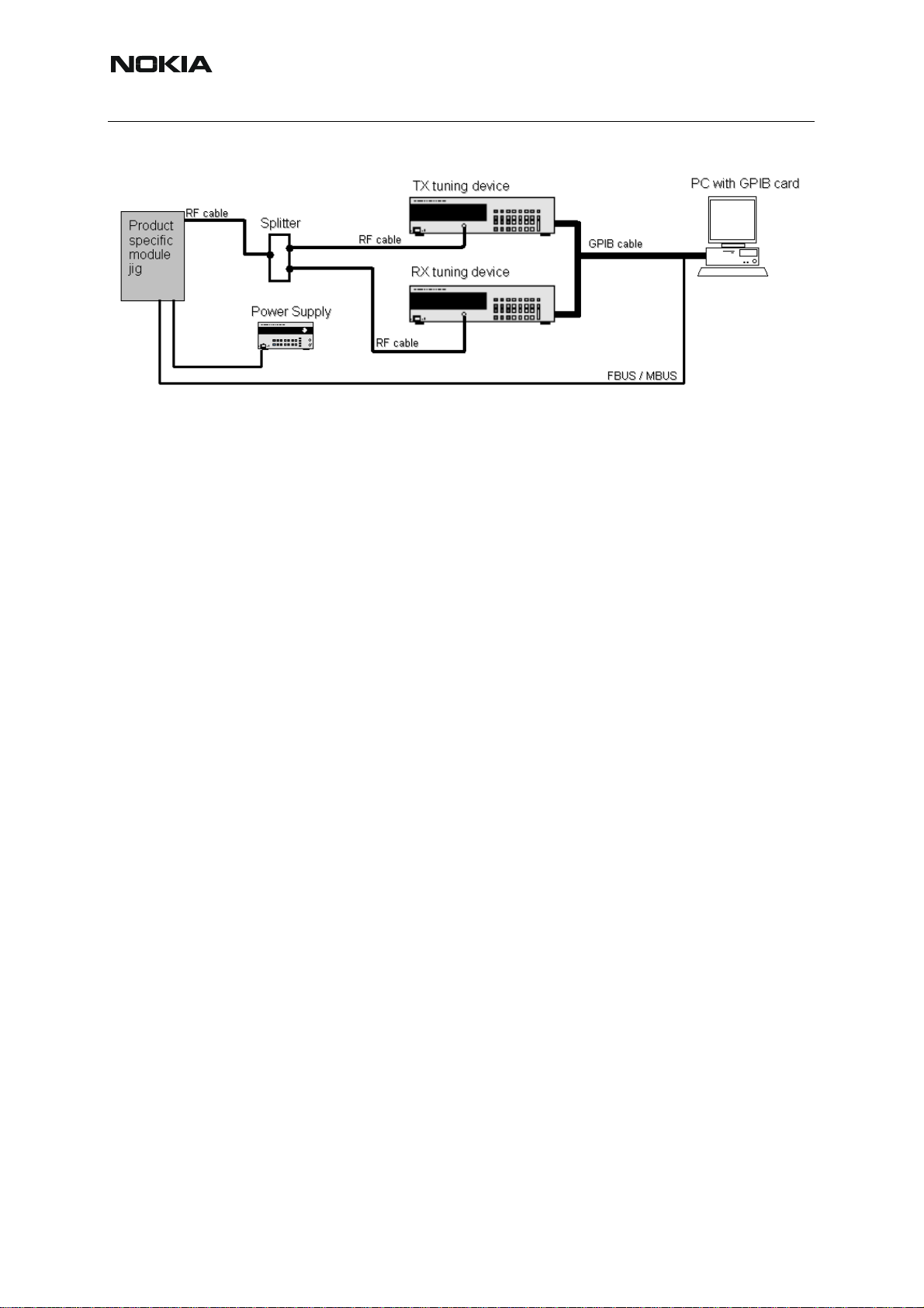
■ Environment
Hardware requirements:
PC with Windows 98/2000/NT
Power supply
Product specific module jig
RF-splitter and -cables
RF equipment (only one of each is needed)
Tx:
Agilent E4406 (VSA series transmitter tester)
Agilent E4445 (PSA series transmitter tester)
Rohde&Schwarz, FSE-family of Signal Analyzers
Rohde&Schwarz, FSIQ-family of Signal Analyzers
Rx:
Agilent ESG family of RF Signal Generators
Rohde&Schwarz, SME-family of Signal Generators
ISSUE 1 09/2004 COMPANY CONFIDENTIAL 57
Copyright © 2004 Nokia. All Rights Reserved.
Page 58
RH-59/60
Nokia Customer Care
Figure 7:Setup environment
GPIB addresses are not defined. Component finds the addresses and uses them automatically .
If several TX tuning devices are connected, this component uses Agilent (VSA or PSA). In RX
side, Agilent has highest priority.
Protection
Components are protected by PKD-1CS, PKD-1NS, PKD-1 and PKD-1P dongles using st an dard TSS protection procedure. Autotuning itself is possible with all these dongles but with PKD1P and PKD-1 dongles user is not able to set the loss.
58 COMPANY CONFIDENTIAL ISSUE 1 09/2004
Copyright © 2004 Nokia. All Rights Reserved.
Page 59

RH-59/60
Nokia Customer Care
Receiver Manual Tuning
■ RX channel select filter calibration
Extra equipment / external RF signal not needed.
Must be done before other RX calibrations.
This function is used to calibrate RX channel select filter in GSM Phones.
Rx Channel select filter is tuned only in one band = Single calibration for both bands.
Select Tuning => Rx Channel select filter calibration.
“Save to Phone “ is checked by default
Uncheck “Save to Phone “ if you don´t want the values to be saved to phone (eg testing)!
Press "Tune" to start the tuning
Tuning values must be 0…31
If values shown are within limits, choose “Stop”
Close the “RX Channel Select Filter Calibration“-dialog to end tuning
Close the Rx Channel select filter calibration dialog, the values are saved to phone
ISSUE 1 09/2004 COMPANY CONFIDENTIAL 59
Copyright © 2004 Nokia. All Rights Reserved.
Page 60
Nokia Customer Care
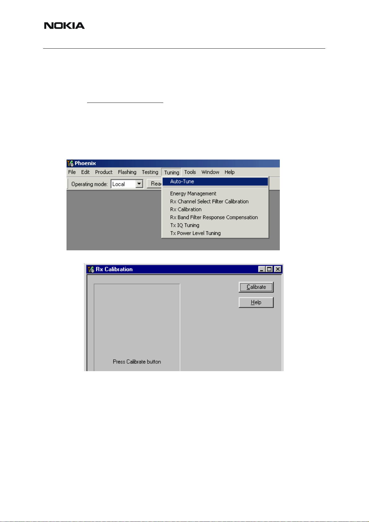
■ RX Calibration
RF generator needed.
This tuning performs RX Calibration.
RH-59/60
Must be done separately on every band
Calibration is automatically performed at GSM850, then at GSM1800 and finally at GSM1900
band. If tuning is successful, it continues in the next band.
AFC tuning is done while GSM850 band RX Calibration is performed.
Remember to take jig and cable attenuations into account!
Select Tuning => Rx calibration
Press “Calibrate"´to start tuning.
!
Set RF generator to required GSM850 frequency => OK
60 COMPANY CONFIDENTIAL ISSUE 1 09/2004
Copyright © 2004 Nokia. All Rights Reserved.
Page 61
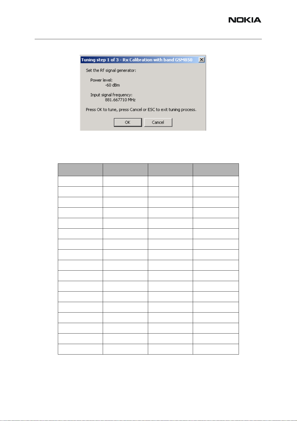
RH-59/60
Set RF generator to required frequency => OK
Tuning values and ADC readings are shown.
Typical values and limits in GSM850 RX Calibration:
Table 2:
Nokia Customer Care
GSM850 Typical value Low limit High limit
Afc value: -90 -350 350
Afc slope: 270 150 350
Rssi 0: 65.09375 58 68
Rssi 1: 71.09375 64 74
Rssi 2: 76.90625 70 80
Rssi 3: 82.90625 76 86
Rssi 4: 88.90625 82 92
Rssi 5: 93.71875 88 98
Rssi 6: 99.71875 94 104
Rssi 7: 105.53125 100 110
Rssi 8: 111.53125 106 116
Rssi 9: 117.53125 112 122
Rssi 10: 123.53125 118 128
Rssi 11: 129.53125 124 134
Rssi 12: 135.53125 130 140
Rssi 13: 141.53125 136 146
Rssi 14: 147.53125 142 152
Set RFgenerator to required GSM1800 frequency => OK
ISSUE 1 09/2004 COMPANY CONFIDENTIAL 61
Copyright © 2004 Nokia. All Rights Reserved.
Page 62

Nokia Customer Care
Tuning values and ADC readings are shown.
Typical values and limits in (GSM1800) RX Calibration
Table 3:
RH-59/60
GSM1800 Typical value Low limit High limit
Rssi 0: 62.40625 58 68
Rssi 1: 68.40625 64 74
Rssi 2: 74.265625 70 80
Rssi 3: 80.265625 76 86
Rssi 4: 86.265625 82 92
Rssi 5: 91.859375 88 98
Rssi 6: 97.859375 94 104
Rssi 7: 103.71875 100 110
Rssi 8: 109.71875 106 116
Rssi 9: 115.71875 112 122
Rssi 10: 121.71875 118 128
Rssi 11: 127.71875 124 134
Rssi 12: 133.71875 130 140
Rssi 13: 139.71875 136 146
Rssi 14: 145.71875 142 152
62 COMPANY CONFIDENTIAL ISSUE 1 09/2004
Copyright © 2004 Nokia. All Rights Reserved.
Page 63

RH-59/60
Set the RF generator to required GSM1900 frequency => OK
Tuning values and ADC readings are shown.
Typical values and limits in (GSM1900) RX Calibration
Table 4:
Nokia Customer Care
GSM1900 Typical value Low limit High limit
Rssi 0: 66.25 61 71
Rssi 1: 72.25 67 77
Rssi 2: 78.09375 73 83
Rssi 3: 84.09375 79 89
Rssi 4: 90.09375 85 95
Rssi 5: 93.25 88 98
Rssi 6: 99.25 94 104
Rssi 7: 105.09375 100 110
Rssi 8: 111.09375 106 116
Rssi 9: 117.09375 112 122
Rssi 10: 123.09375 118 128
Rssi 11: 129.09375 124 134
Rssi 12: 135.09375 130 140
Rssi 13: 141.09375 136 146
Rssi 14: 147.09375 142 152
If values are within limits, they are saved to the phone after successful tuning of each band.
Close the “Rx Calibration” dialog to end tuning
ISSUE 1 09/2004 COMPANY CONFIDENTIAL 63
Copyright © 2004 Nokia. All Rights Reserved.
Page 64

Nokia Customer Care
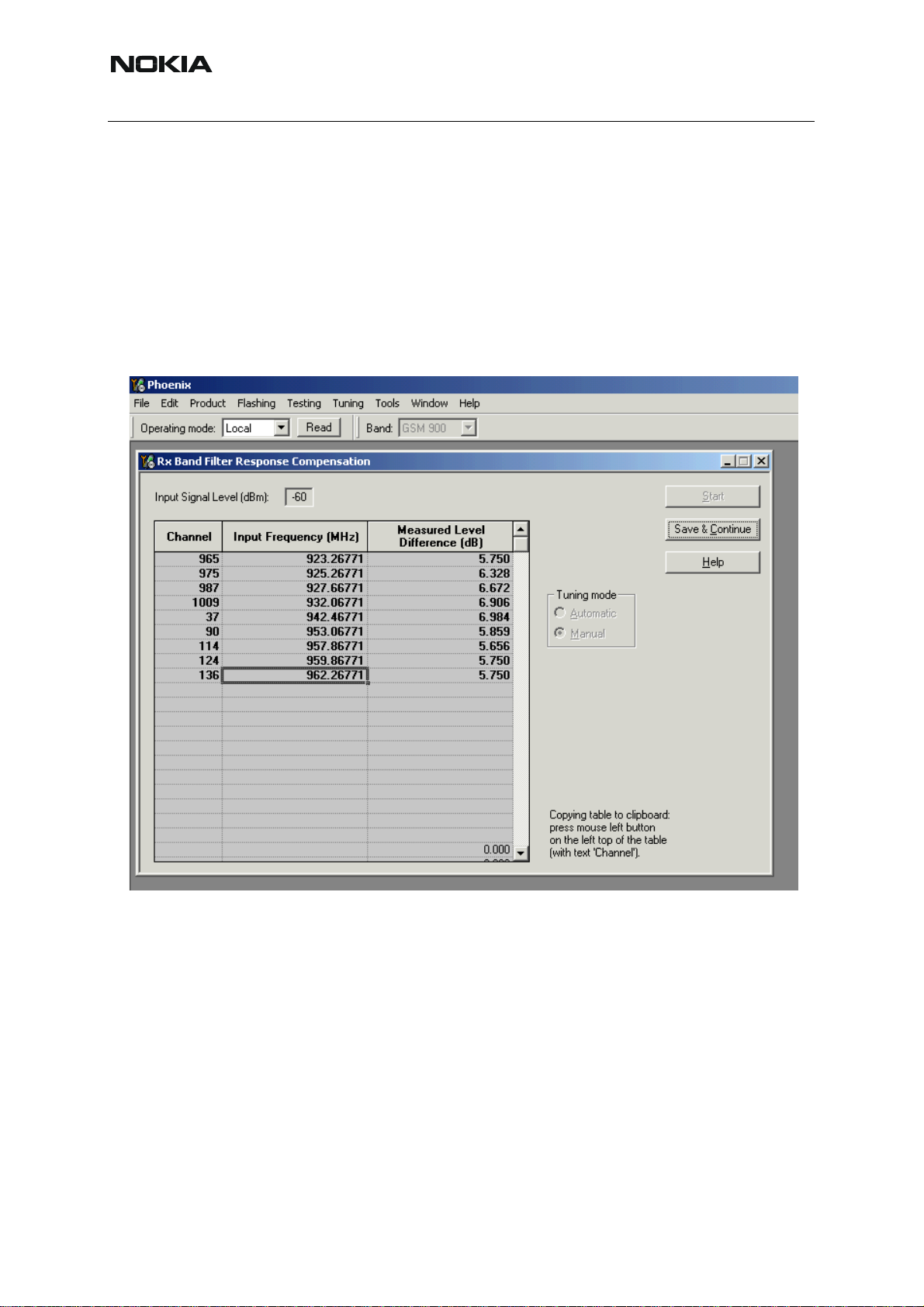
■ RX band filter response compensation
RF generator needed.
RH-59/60
This operation must be done separately on each band
St art RX Calibration at GSM850, then continue at GSM1800 band and finally on the GSM1900
band
NOTE! Remember to do RX calibration before doing Rx Band Filter Response Compensation!
Remember to take jig and cable attenuations into account!
Select Tuning => Rx band filter response compensation
Select “Yes” to start tuning with values already saved to the phone
!
Select "Manual tuning" and tuning starts.
64 COMPANY CONFIDENTIAL ISSUE 1 09/2004
Copyright © 2004 Nokia. All Rights Reserved.
Page 65

RH-59/60
Nokia Customer Care
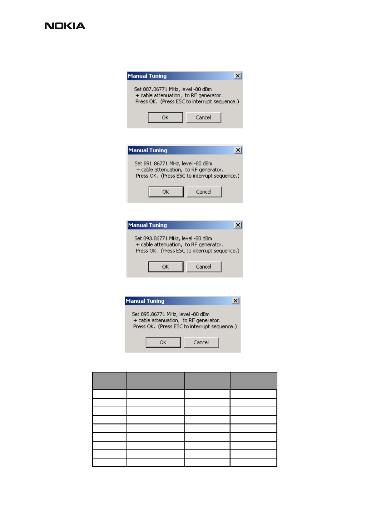
You are asked to supply 9 different RF frequencies to the phone.
The tuning begins from GSM850 band and continues the same way for GSM 1800 and
GSM1900 bands
Set the first required frequency and level => OK
Set the 2nd required frequency and level => OK
Set the 3rd required frequency and level => OK
Set the 4th required frequency and level => OK
Set the 5th required frequency and level => OK
ISSUE 1 09/2004 COMPANY CONFIDENTIAL 65
Copyright © 2004 Nokia. All Rights Reserved.
Page 66
Nokia Customer Care
Set the 6th required frequency and level => OK
Set the 7th required frequency and level => OK
RH-59/60
Set the the 8th required frequency and level => OK
Set 9th required frequency and level => OK
Typical values and limits in Rx Band Filter Response Compensation GSM850:
Input
Channel
Frequency (MHz)
Low limit (dB) High limit (dB)
118 863.26771 -10 3.5
128 869.26771 -3.5 3.5
140 871.66771 -3.5 3.5
172 878.06771 -3.5 3.5
190 881.66771 -3.5 3.5
217 887.06771 -3.5 3.5
241 891.86771 -3.5 3.5
251 893.86771 -3.5 3.5
261 895.86771 -10 3.5
66 COMPANY CONFIDENTIAL ISSUE 1 09/2004
Copyright © 2004 Nokia. All Rights Reserved.
Page 67

RH-59/60
Nokia Customer Care
Choose "Stop, write to PM area"
If the values shown are within limits, choose “Yes” to save values to the phone.
Continue tuning from GSM1800. Choose the correct band from the dropdown menu.
Repeat the same steps as for the GSM850 band above.
Typical values and limits in Rx Band Filter Response Compensation GSM1800:
Input
Channel
Frequency (MHz)
Low limit (dB) High limit (dB)
497 1802.26771 -10 3.5
512 1805.26771 -3.5 3.5
535 1809.86771 -3.5 3.5
606 1824.06771 -3.5 3.5
700 1842.86771 -3.5 3.5
791 1861.06771 -3.5 3.5
870 1876.86771 -3.5 3.5
885 1879.86771 -3.5 3.5
908 1884.46771 -10 3.5
Choose "Stop, write to PM area"
If the values shown are within limits, choose “Yes” to save values to the phone.
ISSUE 1 09/2004 COMPANY CONFIDENTIAL 67
Copyright © 2004 Nokia. All Rights Reserved.
Page 68
RH-59/60
Nokia Customer Care
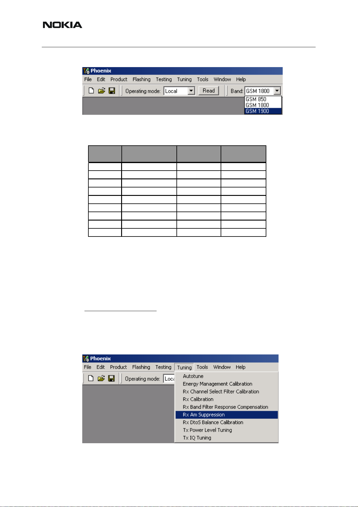
Continue tuning from GSM1900. Choose the correct band from the dropdown menu.
Repeat the same steps as for the GSM850 and GSM1800 bands above.
Typical values and limits in Rx Band Filter Response Compensation GSM1900:
Input
Channel
Frequency (MHz)
Low limit (dB) High limit (dB)
496 1927.06771 -10 3.5
512 1930.26771 -3.5 3.5
537 1935.26771 -3.5 3.5
586 1945.06771 -3.5 3.5
661 1960.06771 -3.5 3.5
736 1975.06771 -3.5 3.5
794 1986.66771 -3.5 3.5
810 1989.86771 -3.5 3.5
835 1994.86771 -10 3.5
Choose "Stop, write to PM area".
If the values shown are within limits, choose “Yes” to save values to the phone.
Close the “RX Band Filter Response Compensation” – dialog to end tuning.
■ Rx Am suppression
RF generator is needed.
Must be done separately on each band
Start RX Am Suppression at GSM850, then continue at GSM1800 band and finally at the
GSM1900 band.
Remember to take jig and cable attenuations into account!
Select Tuning => Rx Am Suppression
!
68 COMPANY CONFIDENTIAL ISSUE 1 09/2004
Copyright © 2004 Nokia. All Rights Reserved.
Page 69

RH-59/60
Press “Start” to begin tuning.
Nokia Customer Care
Adjust signal generator accordingly and press “OK” to tune.
When tuning is finished, press “Save & Continue”.
Tuning continues automatically at GSM1800 band.
ISSUE 1 09/2004 COMPANY CONFIDENTIAL 69
Copyright © 2004 Nokia. All Rights Reserved.
Page 70

Nokia Customer Care
Adjust signal generator accordingly and press “OK” to tune.
When tuning is finished, press “Save & Continue”.
RH-59/60
Tuning continues automatically at GSM1900 band.
Adjust signal generator accordingly and press “OK” to tune.
70 COMPANY CONFIDENTIAL ISSUE 1 09/2004
Copyright © 2004 Nokia. All Rights Reserved.
Page 71

RH-59/60
Nokia Customer Care
When tuning is finished, press “Save & Continue”.
If the Rx Am Suppression tuning was completed successfully, press “OK” to stop tuning.
Close the Rx Am Suppression window.
ISSUE 1 09/2004 COMPANY CONFIDENTIAL 71
Copyright © 2004 Nokia. All Rights Reserved.
Page 72

Nokia Customer Care
■ RX DTOS balance calibration
Extra equipment / external RF signal not needed
RH-59/60
Must be done separately on each band
Start RX Calibration for GSM850, then continue at the GSM1800 band and finally at the
GSM1900 band.
This Calibration is used for calibrating DSP control words values.
Select Tuning => Rx DtoS Balance Calibration
NOTE! No RF-input is allowed to feed when calibrating
Choose “OK” and “Start”, tuning begins automatically at the GSM850 band.
!
Select “OK” to start tuning with values already saved to the phone
72 COMPANY CONFIDENTIAL ISSUE 1 09/2004
Copyright © 2004 Nokia. All Rights Reserved.
Page 73

RH-59/60
Nokia Customer Care
Press “Calibrate”
If values shown are within limits, Select “Stop” choose “Yes” to save values to the phone
Continue tuning from GSM1800. Choose the correct band from the dropdown menu.
Repeat the same steps as for the GSM850 band.
If values shown are within limits, choose “Yes” to save values to the phone.
Continue tuning from GSM1900. Choose the correct band from the dropdown menu.
Repeat the same steps as for the GSM850 and GSM1800 bands.
If values shown are within limits, choose “Yes” to save values to the phone.
Close the RX DtoS Balance Calibration dialog to end Receiver tuning.
ISSUE 1 09/2004 COMPANY CONFIDENTIAL 73
Copyright © 2004 Nokia. All Rights Reserved.
Page 74

Nokia Customer Care
RH-59/60
[This page left intentionally blank]
74 COMPANY CONFIDENTIAL ISSUE 1 09/2004
Copyright © 2004 Nokia. All Rights Reserved.
Page 75

RH-59/60
Nokia Customer Care
RH-59 Manual Alignment with Phoenix
In Phoenix, select connection Fbus and Product Gemini. If you power up the board before selecting Fbus, it works without any error messages. Use the module jig or other device for RF
and Bus connection. Attenuation of the probe alone is 0.5 dB for 900 MHz and 1dB for
1800MHz.
Use CDM55 or other suitable device. Default channels are
37 for GSM900
700 for GSM1800
The alignments must be performed in the order shown to give reliable results.
The way to save data to the phone and to load data from the phone is made different in the
various tunings. Always look what is shown in the windows regarding these issues and act accordingly.
To vary a selected parameter you can use + and – key or in some cases directly type the ne w
value. + and – steps the value for every press. Repeat function seems not to work. In I/Q you
can use the side arrows.
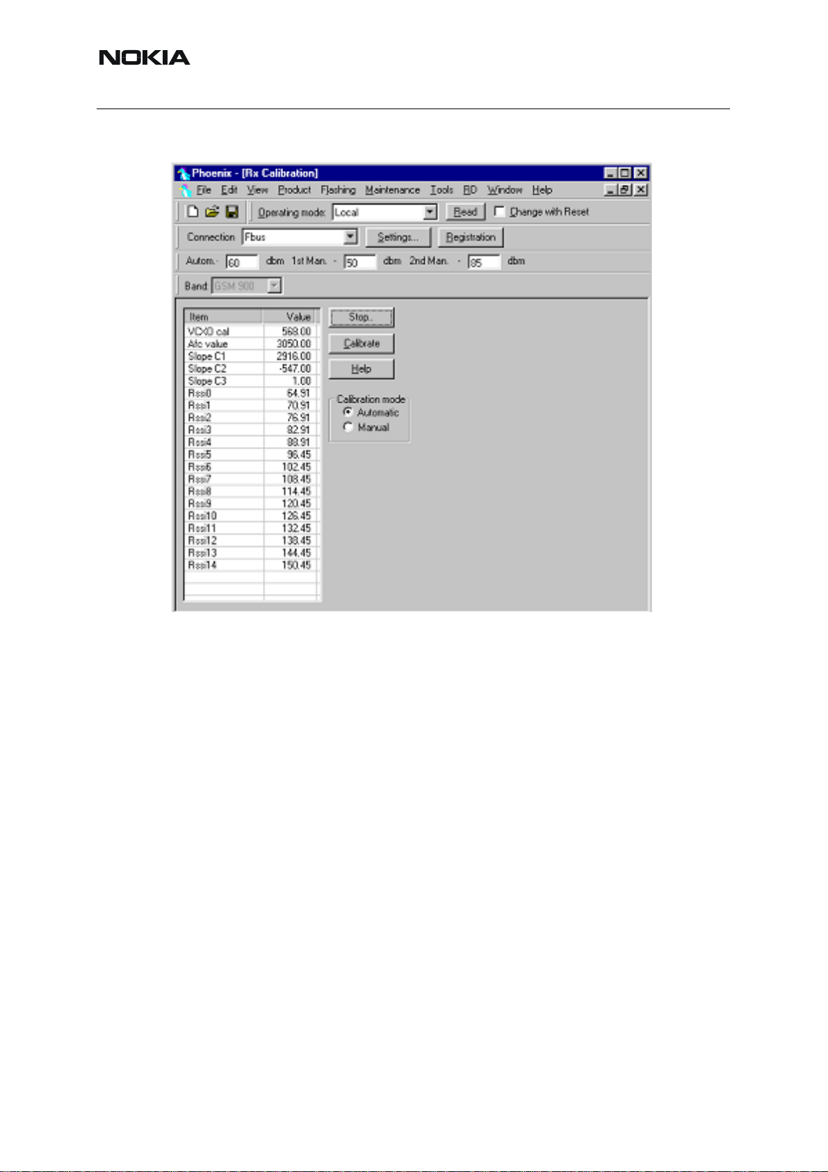
■ RX calibration
Select Maintenance, Tuning, RX Calibration
Select Band: GSM 900
Select Automatic and follow the promts
The result should be like the shown:
ISSUE 1 09/2004 COMPANY CONFIDENTIAL 75
Copyright © 2004 Nokia. All Rights Reserved.
Page 76

Nokia Customer Care
GSM1800 RX calibration
1 The existing data in the phone is shown
2 Calibrate, and the new data is shown
3 Stop, and the little window pops up where you can select to save or not
4 Select GSM1800 in the top bar and repeat at channel 700
RH-59/60
5 The existing data in the phone is shown
6 Calibrate, and the new data is shown
7 Stop, and the little window pops up where you can select to save or not
76 COMPANY CONFIDENTIAL ISSUE 1 09/2004
Copyright © 2004 Nokia. All Rights Reserved.
Page 77

RH-59/60
■ RX channel select filter
1 Select Maintenance, Tuning, Rx Channel Select Filter Calibration
2 Press Start and you can select to load values from the phone or not
3 Press AutoTune
4 Press Stop and you can select to save values to the phone or not
Nokia Customer Care
Note: This calibration requires no input signal
ISSUE 1 09/2004 COMPANY CONFIDENTIAL 77
Copyright © 2004 Nokia. All Rights Reserved.
Page 78
RH-59/60
Nokia Customer Care
■ RX band filter response
1 Select Maintenance, Tuning, Rx Band Filter Response Compensation
2 Press Start, Read from PM area and you can select to load values from the phone or not
3 Press Manual Tuning
4 Set the Signal generator according to the pop-up windows
5 When finished press S top, Write to PM area and you can select to save values to the phone
or not
6 Repeat for GSM1800
Note: This calibration requires a lot of different frequencies from the generator. If you have a signal generator with a frequency list option you can with advantage use Auto Tuning (Dwell should
be around 10ms).
78 COMPANY CONFIDENTIAL ISSUE 1 09/2004
Copyright © 2004 Nokia. All Rights Reserved.
Page 79

RH-59/60
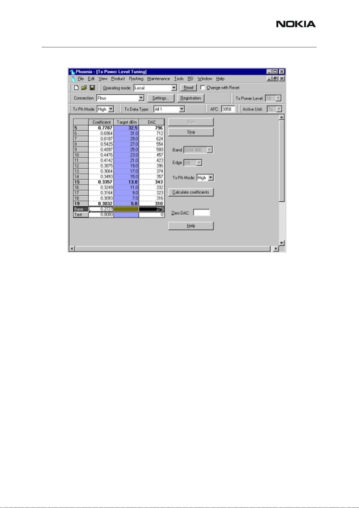
■ Tx power tuning
Select Maintenance, Tuning, Tx Power Level Tuning
TX power tuning GSM
Nokia Customer Care
1 Select edge off, GSM 900
ISSUE 1 09/2004 COMPANY CONFIDENTIAL 79
Copyright © 2004 Nokia. All Rights Reserved.
Page 80

RH-59/60
Nokia Customer Care
2 Press St art and select from where to load values. It is best is to have PC saved dat a from a
good phone. The data from a good phone can be saved to PC for later use. .
3 Select the modulation 1, 0 or random in Tx Data T ype. Select random if a GSM tester is used.
Then it can synchronise to the burst.
4 Select Tx PA Mode High
5 Tune the highlighted values to the wanted power (Use average burst power)
6 Tune base level to –28dBm (CMD55 can keep synchronisation close to the lowest level).
80 COMPANY CONFIDENTIAL ISSUE 1 09/2004
Copyright © 2004 Nokia. All Rights Reserved.
Page 81

RH-59/60
7 Calculate coefficients
Nokia Customer Care
8 Select Tx PA Mode low and tune the high lighted values.
9 The base level coefficient is taken from the high mode. Do not change it.
10 Calculate and select Stop
If you are satisfied with the coefficients and the power, then save to the Permanent memory.
You can also save the table to the PC, so that you can load it to an other phone. Or you can
select not to do anything by removing both ticks.
Only way to end the tuning session is with Yes
ISSUE 1 09/2004 COMPANY CONFIDENTIAL 81
Copyright © 2004 Nokia. All Rights Reserved.
Page 82

Nokia Customer Care
TX power tuning GSM1800
1 Select GSM 1800 band (PCN)
RH-59/60
2 Start
3 Select where to get values from. Normally Permanent Memory
4 OK
82 COMPANY CONFIDENTIAL ISSUE 1 09/2004
Copyright © 2004 Nokia. All Rights Reserved.
Page 83

RH-59/60
Nokia Customer Care
1 Select the wanted modulation. Random if a GSM tester is used, so that you can synchronise
the burst.
2 Only high mode is possible
3 Tune the highlighted values to the wanted power
4 Tune base level to –27dBm
5 Stop
6 Select where to save the values, one, both or no one can be selected.
7 Yes. That is the only way to end tuning.
ISSUE 1 09/2004 COMPANY CONFIDENTIAL 83
Copyright © 2004 Nokia. All Rights Reserved.
Page 84

Nokia Customer Care
■ I/Q tuning
Select Maintenance, Tuning, Tx IQ tuning
Set CMD55 to Narrow Spectrum on the same band as the phone.
Selected in the top menu..
RH-59/60
1 Select where to get values. Normally select Load From Product
2 Start
3 Tune offset values to lowest carrier. Use Side arrows or +, - .
4 Tune Amplitude and phase to lowest sideband.
84 COMPANY CONFIDENTIAL ISSUE 1 09/2004
Copyright © 2004 Nokia. All Rights Reserved.
Page 85

RH-59/60
5 Check eventually with other modulation (0).
Nokia Customer Care
Remember to tick Save to Product
if you want to save the values in the phone.
6 Stop to end the tuning with the selected save option .
The same procedure for PCN as for GSM.
Remember to tick Save To Product.
Stop. Ends tuning .
ISSUE 1 09/2004 COMPANY CONFIDENTIAL 85
Copyright © 2004 Nokia. All Rights Reserved.
Page 86

RH-59/60
Nokia Customer Care
■ RF control
THE purpose of this feature is to check the receiver or transmitter without going in call. It works
very much like a call, but you have control via the PC, and not via the tester.
The TX mode GSM900 can select between Free, High and L ow mode. It changes the P A mode,
but changes also the power level if a level selected is not supported in that mode.
If you want to tune at other channels than the default, then you must select it first in RF control
and then start the tuning.
86 COMPANY CONFIDENTIAL ISSUE 1 09/2004
Copyright © 2004 Nokia. All Rights Reserved.
Page 87

RH-59/60
Nokia Customer Care
■ Call testing
If all tunings are done and the phone TX and RX are working, a call is the ultimate test of the
phone.
Set CMD55, or similar tester, to manual test and switch the phone to normal if it was in local.
Remember to have a test simcard in the phone.
When the phone has made a registration a call can be made, and it is possible to let the phone
answer via Phoenix. In the Autocaller (Maintenance Testing) you can answer by ticking Answer
when button pushed and then posh the button.
ISSUE 1 09/2004 COMPANY CONFIDENTIAL 87
Copyright © 2004 Nokia. All Rights Reserved.
Page 88

Nokia Customer Care
RH-59/60
[This page left intentionally blank]
88 COMPANY CONFIDENTIAL ISSUE 1 09/2004
Copyright © 2004 Nokia. All Rights Reserved.
Page 89

RH-59/60
Nokia Customer Care
RH-60 Manual Alignment with Phoenix
In Phoenix select connection Fbus and Product Gemini. If you power up the board before selecting Fbus, it works without any error messages. Use Jig or other device for RF and bus connection. Attenuation in the probe alone is 0.5dB for 850 and 1dB for 1900. Use CMD55 or oth er
suitable device.
Default channels are: 37 for GSM850 and
661 for GSM1900.
The alignments must be performed in the order shown to give reliable results.
The way to save data to the phone and to load data from the phone is made different in the
various tunings. Always look what is shown in the windows regarding these issues and act accordingly.
To vary a selected parameter you can use + and – key or in some cases directly type the ne w
value. + and – steps the value for every press. Repeat function seems not to work. In I/Q you
can use the side arrows.
■ RX calibration
Select Maintenance, Tuning, RX Calibration
Select Band: GSM850
Select Automatic and follow the prompts
The window should look like this:
1 Select Automatic, set to 60dBm in small window in top bar
2 Start and select PM settings in the start parameters that pop up
ISSUE 1 09/2004 COMPANY CONFIDENTIAL 89
Copyright © 2004 Nokia. All Rights Reserved.
Page 90
Nokia Customer Care
3 OK
RH-59/60
The existing data in the phone is shown
1 Calibrate, and the new data is shown
2 Stop, and the little window pops up where you can select to save or not
3 Select GSM1900 in the top bar and repeat at channel 661.
90 COMPANY CONFIDENTIAL ISSUE 1 09/2004
Copyright © 2004 Nokia. All Rights Reserved.
Page 91

RH-59/60
Nokia Customer Care
1 The existing data in the phone is shown
2 Calibrate, and the new data is shown
3 Stop, and the little window pops up where you can select to save or not
ISSUE 1 09/2004 COMPANY CONFIDENTIAL 91
Copyright © 2004 Nokia. All Rights Reserved.
Page 92

Nokia Customer Care
■ Tx power tuning
Select Maintenance, Tuning, Tx Power Level Tuning
TX power tuning GSM
RH-59/60
1 Select edge off, GSM 850
2 Press St art and select from where to load values. Best is to have PC saved data from a good
phone. The data from a "good" phone can be saved to PC, for use later.
92 COMPANY CONFIDENTIAL ISSUE 1 09/2004
Copyright © 2004 Nokia. All Rights Reserved.
Page 93
RH-59/60
.
Nokia Customer Care
3 Select the modulation 1, 0 or random in Tx Data T ype. Select random if a GSM tester is used.
Then it can synchronise to the burst.
4 Select Tx PA Mode High
5 Tune the highlighted values to the wanted power (Use average burst power)
6 Tune base level to –28dBm (CMD55 can keep synchronisation close to the lowest level )
ISSUE 1 09/2004 COMPANY CONFIDENTIAL 93
Copyright © 2004 Nokia. All Rights Reserved.
Page 94

Nokia Customer Care
7 Calculate coefficients
RH-59/60
8 Select Tx PA Mode low and tune the high lighted values.
9 The base level coefficient is taken from the high mode. Do not change it.
10 Calculate and select Stop
If you are satisfied with the coefficients and the power, then save to the Permanent memory.
You can also save the table to the PC, so that you can load it to an other phone. Or you can
select not to do anything by removing both ticks.
The only way to end the tuning session is with Yes
94 COMPANY CONFIDENTIAL ISSUE 1 09/2004
Copyright © 2004 Nokia. All Rights Reserved.
Page 95

RH-59/60
TX power tuning GSM1900
1 Select GSM 1900 band (PCN)
Nokia Customer Care
2 Start
3 Select where to get values from. Normally Permanent Memory
4 OK
ISSUE 1 09/2004 COMPANY CONFIDENTIAL 95
Copyright © 2004 Nokia. All Rights Reserved.
Page 96

Nokia Customer Care
RH-59/60
1 Select the wanted modulation. Random if a GSM tester is used, so that you can synchronise
the burst.
2 Only high mode is possible
3 Tune the highlighted values to the wanted power
4 Tune base level to –27dBm
5 Stop
6 Select where to save the values, one, both or no one can be selected.
7 Yes. That is the only way to end tuning.
96 COMPANY CONFIDENTIAL ISSUE 1 09/2004
Copyright © 2004 Nokia. All Rights Reserved.
Page 97

RH-59/60
■ I/Q tuning
Select Maintenance, Tuning, Tx IQ tuning
Set CMD55 to Narrow Spectrum on the same band as the phone.
Selected in the top menu..
Nokia Customer Care
1 Select where to get values. Normally select Load From Product
2 Start
3 Tune offset values to lowest carrier. Use Side arrows or +, - .
4 Tune Amplitude and phase to lowest sideband.
ISSUE 1 09/2004 COMPANY CONFIDENTIAL 97
Copyright © 2004 Nokia. All Rights Reserved.
Page 98

Nokia Customer Care
5 Check eventually with other modulation (0).
RH-59/60
Remember to tick Save to Product
if you want to save the values in the phone.
98 COMPANY CONFIDENTIAL ISSUE 1 09/2004
Copyright © 2004 Nokia. All Rights Reserved.
Page 99

RH-59/60
6 Stop to end the tuning with the selected save option .
Nokia Customer Care
The same procedure for all GSM bands.
Remember to tick Save To Product.
Stop. Ends tuning.
ISSUE 1 09/2004 COMPANY CONFIDENTIAL 99
Copyright © 2004 Nokia. All Rights Reserved.
Page 100

RH-59/60
Nokia Customer Care
■ RF control
This menu can be placed in maintenance or in tuning dependent of Phoenix.
It is meant to check the receiver or transmitter without going in call. It works very much like a
call, but you have control via the PC, and not via the tester. The TX mode GSM850 can select
between Free, High and Low mode. It changes the PA mode, but changes also the power level
if a level is selected that is not supported in that mode.
If you want to tune at other channels than the default, then you must select it first in RF control
and then start the tuning.
If you want to tune at other channels than the default, then you must select it first in RF control
and then start the tuning.
100 COMPANY CONFIDENTIAL ISSUE 1 09/2004
Copyright © 2004 Nokia. All Rights Reserved.
 Loading...