

Page 1

Programmes After Market Services
NHA–3 Series Transceivers
Chapter 4
Uif Module
Issue 2 06/98
Page 2

NHA–3
Uif Module
Technical Documentation
CONTENTS
Introduction 4 – 3. . . . . . . . . . . . . . . . . . . . . . . . . . . . . . . . . . . . . . . . . . . . . . . . . . . . . .
Technical Summary 4 – 3. . . . . . . . . . . . . . . . . . . . . . . . . . . . . . . . . . . . . . . . . . . .
List of Submodules 4 – 3. . . . . . . . . . . . . . . . . . . . . . . . . . . . . . . . . . . . . . . . . . . .
Technical Specifications 4 – 4. . . . . . . . . . . . . . . . . . . . . . . . . . . . . . . . . . . . . . . . . . .
External Signals and Connections 4 – 5. . . . . . . . . . . . . . . . . . . . . . . . . . . . . . .
Internal Signals and Connections 4 – 8. . . . . . . . . . . . . . . . . . . . . . . . . . . . . . . .
Functional Description 4 – 10. . . . . . . . . . . . . . . . . . . . . . . . . . . . . . . . . . . . . . . . . . . .
Buzzer Driving Circuit 4 – 10. . . . . . . . . . . . . . . . . . . . . . . . . . . . . . . . . . . . . . . . . .
Earpiece Driving Circuit 4 – 10. . . . . . . . . . . . . . . . . . . . . . . . . . . . . . . . . . . . . . . .
Display Interface 4 – 10. . . . . . . . . . . . . . . . . . . . . . . . . . . . . . . . . . . . . . . . . . . . . .
PAMS
Page No
Keypad interface circuitry 4 – 10. . . . . . . . . . . . . . . . . . . . . . . . . . . . . . . . . . . . . . .
Accessory Interface 4 – 10. . . . . . . . . . . . . . . . . . . . . . . . . . . . . . . . . . . . . . . . . . .
LED Driving Circuits 4 – 11. . . . . . . . . . . . . . . . . . . . . . . . . . . . . . . . . . . . . . . . . . .
Accessory Interface Components 4 – 11. . . . . . . . . . . . . . . . . . . . . . . . . . . . . . . .
ESD Protection 4 – 11. . . . . . . . . . . . . . . . . . . . . . . . . . . . . . . . . . . . . . . . . . . . . . .
Parts Lists 4 – 12. . . . . . . . . . . . . . . . . . . . . . . . . . . . . . . . . . . . . . . . . . . . . . . . . . . . . . .
List of Figures
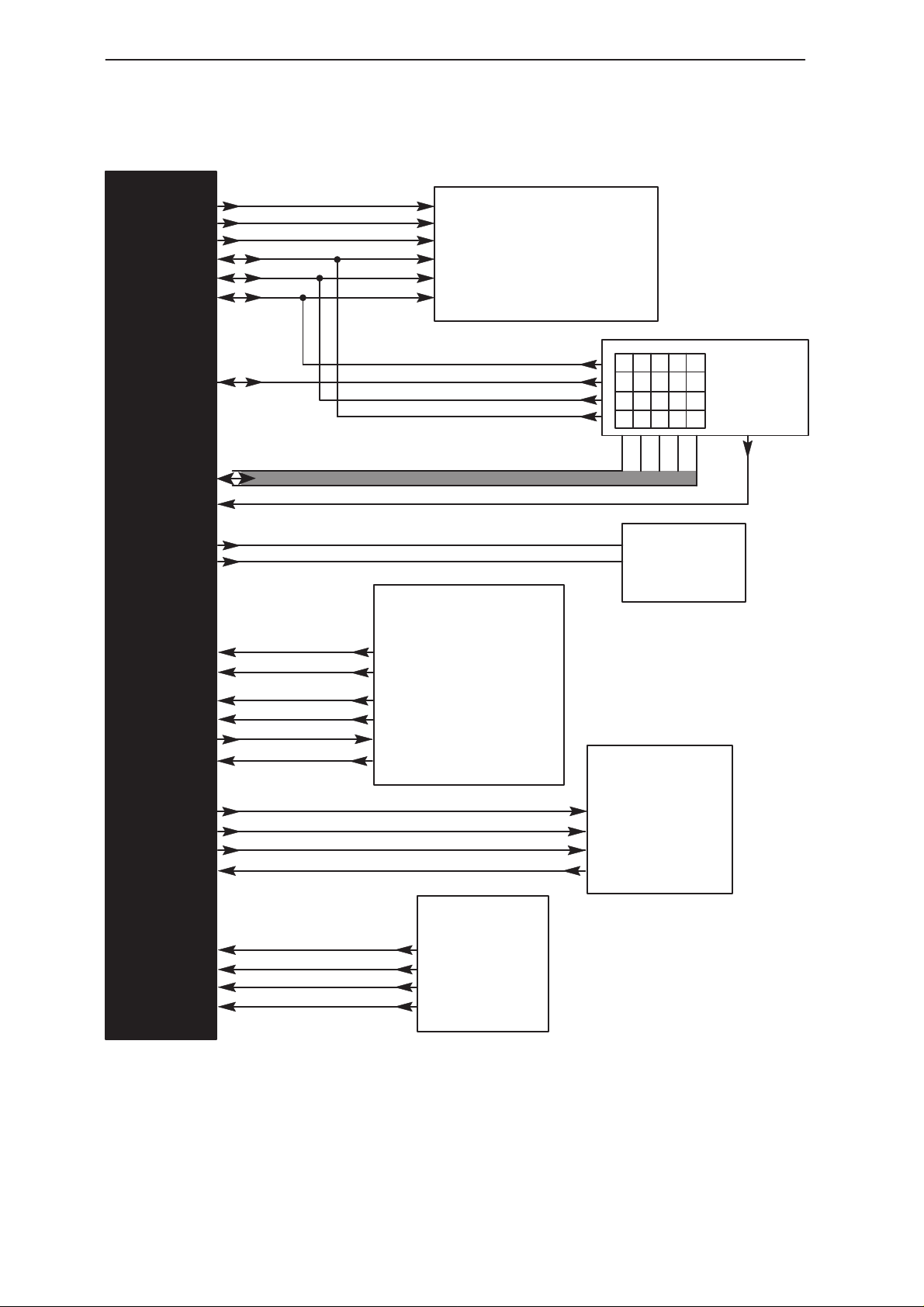
Figure 1. UI Module Block Diagram 4 – 4. . . . . . . . . . . . . . . . . . . . . . . . . . . . . . .
Figure 2. System Connector Pinout 4 – 6. . . . . . . . . . . . . . . . . . . . . . . . . . . . . . .
Version 10
Figure 3 UIF Circuit Diagram 4–A1. . . . . . . . . . . . . . . . . . . . . . . . . . . . . . . . . . . .
Figure 4 Keypad Circuit Diagram 4–A2. . . . . . . . . . . . . . . . . . . . . . . . . . . . . . . . .
Figure 5 Component Layouts 4–A3. . . . . . . . . . . . . . . . . . . . . . . . . . . . . . . . . . . . .
Version 11
Page No
Figure 6 UIF Circuit Diagram 4–A4. . . . . . . . . . . . . . . . . . . . . . . . . . . . . . . . . . . .
Figure 7 Keypad Circuit Diagram 4–A5. . . . . . . . . . . . . . . . . . . . . . . . . . . . . . . . .
Figure 8 Component Layouts 4–A6. . . . . . . . . . . . . . . . . . . . . . . . . . . . . . . . . . . . .
Note: In printed manuals all A3 drawings are located at the back of the binder
Page 4 – 2
Issue 2 06/98
Page 3
PAMS
NHA–3
Technical Documentation
Introduction
Technical Summary
H700 User interface module consists of the following parts:–
Display with driving IC;
Backlighting circuits;
Earpiece driver circuit;
Buzzer driver circuit;
Keypad contacts and circuitry;
Accessory interface circuits;
Protection components on charger input.
List of Submodules
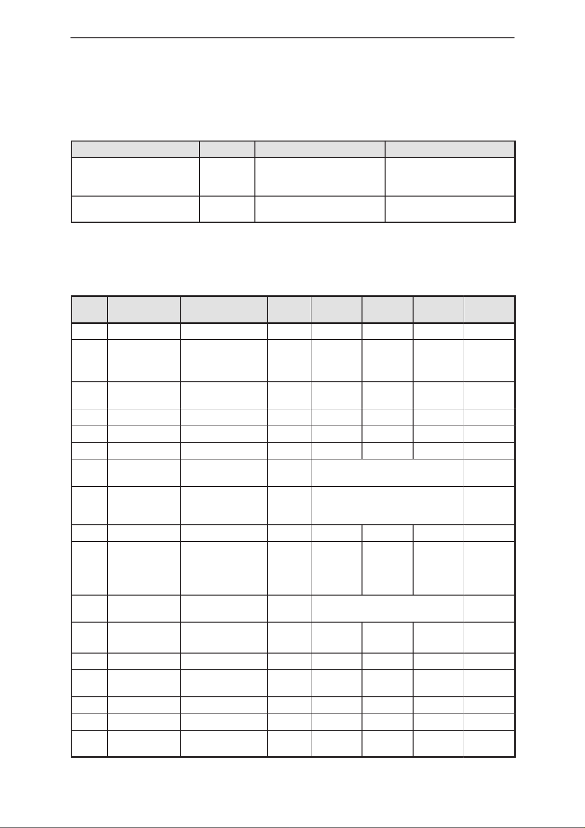
Table 4. List of Submodules
Name of submodule Type code Material
code
CUI1+ display module 4850025
Uif Module
Notes
Issue 2 06/98
Page 4 – 3
Page 4
NHA–3
Uif Module
Technical Specifications
PAMS
Technical Documentation
LCDCLK
LCDRstX
LCDENX
LCDDC_Col0
LCDSDA_Col1
LCDSDCLK_Col3
Col2
Row(0:4)
PwrkeyX
Light0
Light1
VCH
ChrgCtrl
ReqA
MBUS
HEAR
Board to Board Connector
XMic
EARP
IntEarEn
BuzzPWM
MIC
LCDCLK
Reset
LCDENX
LCDDC
LCDSDA
LCDSDCLK
System Connector
& Charger Socket
VCH
ChrgCtrl
ReqA
MBUS
HEAR
XMic
UI Display
Col3
Col2
Col1
Col0
Audio Circuits
EARP
IntEarEn
BuzzPWM
MIC
Row1
Row2
Row0
Row3
Backlights
Internal
Keypad
PwrkeyX
Row4
BSI
BTEMP
VBATT
GND
Page 4 – 4
Battery
Connections
BSI
BTEMP
VBATT
GND
Figure 1. UI Module Block Diagram
Issue 2 06/98
Page 5
PAMS
NHA–3
Technical Documentation
External Signals and Connections
Table 5. List of Connectors
Connector Name Code Notes Specifications / Ratings
System Connector 5469041 Includes recess with spring
contacts for Mic & dc jack
socket for charger
Inter–board connector 5469049 44–way connection to sys-
tem module
Table 6. System Connector X502
Pin
No.
1 AGND Analogue Ground
Name Function Input/
Output
Minimum
Typical /
Nominal
Maxi-
mum
Uif Module
Unit
2 BTEMP_Vi-
bEn
3 MIC Internal Micro-
4 VBATT Battery Voltage 3.2 3.6 5.1 V
5 GND System Ground
6 GND System Ground
7 MBUS Serial data inter-
8 ReqA Request for Ac-
9 SGND
10 XMIC Accessory Micro-
11 HEAR Headset earpiece
12 VIN Charger Voltage I/P 16.9
13 (JackDet)
Battery Temperature detection
Vibra enable
phone signal
face
cessory
phone signal
signal
I/P 0.04
10
I/P 22.4 mV p–p
I/O Digital signal levels + interrupt
capability
I/P Digital Interrupt + A–D I/P to
engine to determine accessory
ID
I/P 89 (HF)
6.0
(Headset
)
O/P Level depends on the accessory
connected
2.8 V
6800 mV p–p
900
kHz
V
mA
14 ChrgCtrl Charger control
signal
15 GND System Ground
16 ChrgCtrl See 14 above
17 BSI Battery size
detection
Issue 2 06/98
O/P 30 37 Hz
I/P 0.04 2.8 V
Page 4 – 5
Page 6

NHA–3
Uif Module
PAMS
Technical Documentation
Table 6. System Connector X502 (continued)
FunctionNamePin
No.
18 VIN See 12 above
19 GND System Ground
20 GND System Ground
AGND
BTEMP
MIC
VBATT
123 4 5
GND
GND
6789
MBUS
REQA
Input/
Output
XMIC
SGND
Minimum
VIN
HEAR
10 11 12 13 14
Typical /
Nominal
ChrgCtrl
JACKDET
GND
15
UnitMaxi-
mum
ChrgCtrl
BSI
16 17 18 19 20
VIN
GND
GND
Figure 2. System connector –pinout
Table 7. Inter–board Connector X501
Pin
No.
1 – 4 VBATT Battery Voltage 3.2 3.6 5.1 V
5 EARP Internal Earpiece
6 PwrKeyX Power On signal O/P Active low
7 LCDSDCLK_C
8 LCDDC_Col0 Mux’d LCD data
9 Row1 Keypad Row 1 I/P Digital signal levels
10 Row0 Keypad Row 0 I/P Digital signal levels
11 Col2 Keypad Column 2 I/O Digital signal levels
12 LCDSDA_Col1Mux’d LCD serial
13 ChrgCtrl Charger control
Name Function Input/
signal
Mux’d display
ol3
data clock & keypad Column 3
or command &
Keypad Column 0
data & Keypad
Column 1
signal
Mini-
Output
I/P 20.4 48.0 115 mV p–p
I/O Digital signal levels
I/O Digital signal levels
I/O Digital signal levels
O/P 30 37 Hz
mum
Typical /
Nominal
Maxi-
mum
Unit
Page 4 – 6
Issue 2 06/98
Page 7

PAMS
NHA–3
Technical Documentation
Table 7. Inter–board Connector X501 (continued)
FunctionNamePin
No.
14 MBUS Serial data inter-
face
15–18 GND System Ground
19–22 VCH Charger Voltage O/P 16.9
23 MIC Internal Micro-
phone signal
24 AGND Analogue Ground
25 XMIC Accessory Micro-
phone signal
26 HEAR Headset earpiece
signal
27 EARN for NED usage
Input/
Output
I/P Digital signal levels + interrupt
O/P 22.4 mV p–p
O/P 89 (HF)
I/P Level depends on the accessory
Minimum
capability
connected
Typical /
Nominal
900
6800 mV p–p
6.0
(Headset
)
Uif Module
UnitMaxi-
mum
V
mA
28 BTEMP_Vi-
bEn
29 BSI Battery size
30 Row2 Keypad Row 2 O/P Digital signal levels
31 Row3 Keypad Row 3 O/P Digital signal levels
32 Row4 Keypad Row 4 O/P Digital signal levels
33 VBB Regulated base-
34 LCDRstX Reset for display
35 Spare
36 LCDENX Display driver en-
37 ReqA Request for Ac-
38 Spare
39 Spare
Battery Tempera-
ture detection
Vibra enable
detection
band supply volt-
age
driver
able
cessory
O/P 0.04
10
O/P 0.04 2.8 V
I/P 2.8 2.96
I/P Digital signal levels – low pulse
I/P Digital signal levels – active low
O/P Digital Interrupt + A–D I/P to
engine to determine accessory
ID
2.8 V
5
kHz
V
mA
40 Light0 Keypad backlight
control
41 Light1 Display LED con-
trol
Issue 2 06/98
I/P Digital signal levels – Active high
I/P Digital signal levels – Active high
Page 4 – 7
Page 8

NHA–3
Uif Module
PAMS
Technical Documentation
Table 7. Inter–board Connector X501 (continued)
FunctionNamePin
No.
42 LCDCLK Display driver
clock
43 BuzzPWM PWM signal to
Buzzer
44 IntEarEn Internal Earpiece
Enable
Pinout for vertically aligned
connector (LHS of phone
viewed from front.)
LCDSDCLK_Col3
VBATT
VBATT
VBATT
VBATT
EarP
PwrKeyX
LCDDC_COL0
Row1
Row0
Col2
LCDSDA_Col1
ChrgCtrl
MBUS
GND
GND
GND
GND
VCH
VCH
VCH
VCH
Input/
Output
Minimum
Typical /
Nominal
mum
UnitMaxi-
I/P 160 kHz
I/P Frequency & mark/space ratio
are adjusted to give required
ring–tones
I/O Digital signal levels – Active high
1
1
2
3
4
5
6
7
8
9
10
11
12
13
14
15
16
17
18
19
20
21
22
44
43
42
41
40
39
38
37
36
35
34
33
32
31
30
29
28
27
26
25
24
23
IntEarEn
BuzzPWM
LCDCLK
Light1
Light0
Spare
Spare
ReqA
LCDENX
Spare – for possible NED usage
LCDRstX
VBB
Row4
Row3
Row2
BSI
BTEMP
EARN
HEAR
XMIC
AGND
MIC
Internal Signals and Connections
Pin 1 is on the Left side of the PCB with the board viewed from the
Keypad side and the display at the top.
Page 4 – 8
Issue 2 06/98
Page 9

PAMS
VDD=V0V1V2V3V4V5
NHA–3
Technical Documentation
Table 8. Display Module Connections
Connec-
tion No.
1 NC No Connect
2 RES LCDRstX Reset
3 IF GND Data length select pin for parallel interface
4 P/S GND HI for parallel I/F, LO for serial
5 CK LCDCLK External clock input for LCD
6 VDD VBB System supply voltage
7 VSS GND System Ground
8 CAP1+ Boosting Capacitor (C109) positive pin
9 CAP1– Boosting Capacitor (C109) negative pin
10 CAP2+ Boosting Capacitor (C108) positive pin
11 CAP2– Boosting Capacitor (C108) negative pin
Signal
Name at
Module
PCB Connection
Name
Description
Uif Module
12 VOUT Output pin for boosting – connection for smoothing
capacitor (C107) to VDD
13 VR Voltage regulating pin – gives voltage between VDD
& V5 by resistance division
14 V0
15 V1
16 V2
17 V3
18 V4
19 V5
20 VSS GND System Ground
21 VDD VBB System supply voltage
22 SCL LCDSDCLK_Col3 Serial Data Clock
23 SI LCDSDA_Col1 Serial Data
24 /CS LCDENX Chip select – active LO
25 /WR GND Write enable – active LO
26 A0 LCDDC_Col0 Selects Command or Data transfer, LO for Com-
27 NC No Connect
Multi–level power supply for liquid crystal drive.
Where:–
VDD=V
VDDVSSV5VOUT
mand, HI for Data
V1V2V
V4V
Issue 2 06/98
Page 4 – 9
Page 10

NHA–3
Uif Module
Functional Description
Buzzer Driving Circuit
This comprises R506,C502,V500,R504,R507,V502,V501 & buzzer H500
The input is a PWM signal whose frequency and mark–space ratio
determine the pitch and loudness of the buzzer. The signal is generated
by a PWM output on the system board’s MCU.
Earpiece Driving Circuit
This comprises R501,V500,R502,C503,R512,R513,R514,V507,C505
driver IC N500,R518 & the earpiece B500
The driver enable signal IntEarEn is active HI at the system board
interface. The transistor circuit with V500 inverts it to the correct logic for
the driver IC N500.
PAMS
Technical Documentation
The EARP analogue signal is single–ended and the driver IC N1 provides
the amplification necessary to achieve the required output levels at the
speaker. Volume control is achieved by varying the input levels by means
of the ASIC on the system module.
Display Interface
The display driving IC is present on the display module. This part requires
some external components (R & C) to operate correctly. These are C600
C601,C602,C603,C604,C605,C606,C607,R612, R613 & C608
The interface is described earlier in Table 5.
Keypad Interface Circuitry
The keypad allows for the power key to be located in 2 different places –
one is at the top right of the phone, the other is the top left of the main key
area. V600, R600 & R601 are required for this to function.
The power key operates by pulling PwrKeyX LO, this is a dedicated input
to the System module.
Three of the keypad Column connections are multiplexed with display
driving signals. The following 3 resistors are required to enable the keypad
& display to work correctly together: R602, R603, R604.
Accessory Interface
The UI module provides the route for the Accessory audio and control
signals from the system module to the system connector.
Page 4 – 10
Issue 2 06/98
Page 11

PAMS
NHA–3
Technical Documentation
LED Driving Circuits
Keypad Backlight LED driving is via R608, R609, V602, V603, R610 &
R611.
Display Backlight LED driving is via R605, R606, V601 & R607.
In both cases a HI signal on the Contol line (Light0 or Light1) will turn the
relevant transitor on and cause conduction of current from VBATT via the
LEDs and the transistor emittor resistor. The function of the emittor
resistor is to set the total current available to the LEDs in the
corresponding circuit.
ESD Protection
ESD protection is provided by spark gaps placed on certain signals plus
clamping diodes – V508, V509, V503, V505 – on 4 of the system
connector signals: HEAR; ReqA; MBUS; and XMIC respectively.
Uif Module
Issue 2 06/98
Page 4 – 11
Page 12

NHA–3
Uif Module
Technical Documentation
Parts List
Amps UI Module
p.n 0200785 EDMS issue 10.4 PCB version 10
Item Code Description Value Type
R501 1430065 Chip resistor 10 k 5 % 0.063 W 0603
R502 1430087 Chip resistor 100 k 5 % 0.063 W 0603
R504 1430023 Chip resistor 820 5 % 0.063 W 0603
R506 1430043 Chip resistor 2.2 k 5 % 0.063 W 0603
R508 1430167 Chip resistor 47 5 % 0.063 W 0603
R512 1430071 Chip resistor 22 k 5 % 0.063 W 0603
R513 1430083 Chip resistor 68 k 5 % 0.063 W 0603
R514 1430035 Chip resistor 1.0 k 5 % 0.063 W 0603
R515 1430017 Chip resistor 390 5 % 0.063 W 0603
R516 1430087 Chip resistor 100 k 5 % 0.063 W 0603
R517 1430144 Chip jumper 0603
R518 1430007 Chip resistor 180 5 % 0.063 W 0603
R600 1430043 Chip resistor 2.2 k 5 % 0.063 W 0603
R601 1430043 Chip resistor 2.2 k 5 % 0.063 W 0603
R602 1430043 Chip resistor 2.2 k 5 % 0.063 W 0603
R603 1430043 Chip resistor 2.2 k 5 % 0.063 W 0603
R604 1430043 Chip resistor 2.2 k 5 % 0.063 W 0603
R605 1430023 Chip resistor 820 5 % 0.063 W 0603
R606 1430035 Chip resistor 1.0 k 5 % 0.063 W 0603
R607 1430157 Chip resistor 18 5 % 0.063 W 0603
R608 1430023 Chip resistor 820 5 % 0.063 W 0603
R609 1430035 Chip resistor 1.0 k 5 % 0.063 W 0603
R610 1430163 Chip resistor 33 5 % 0.063 W 0603
R611 1430159 Chip resistor 22 5 % 0.063 W 0603
R612 1414357 Chip resistor 590 k 1 % 0.1 W 0805
R613 1430217 Chip resistor 634 k 1 % 0.063 W 0603
C500 2320107 Ceramic cap. 10 n 5 % 50 V 0603
C502 2320107 Ceramic cap. 10 n 5 % 50 V 0603
C503 2320781 Ceramic cap. 47 n 20 % 16 V 0603
C505 2312410 Ceramic cap. 1.0 u 10 % 16 V 1206
C506 2320075 Ceramic cap. 470 p 5 % 50 V 0603
C508 2320107 Ceramic cap. 10 n 5 % 50 V 0603
C513 2312410 Ceramic cap. 1.0 u 10 % 16 V 1206
C600 2320779 Ceramic cap. 100 n 10 % 16 V 0603
C601 2320779 Ceramic cap. 100 n 10 % 16 V 0603
C602 2320779 Ceramic cap. 100 n 10 % 16 V 0603
C603 2320779 Ceramic cap. 100 n 10 % 16 V 0603
C604 2320779 Ceramic cap. 100 n 10 % 16 V 0603
C605 2312410 Ceramic cap. 1.0 u 10 % 16 V 1206
PAMS
Page 4 – 12
Issue 2 06/98
Page 13

PAMS
NHA–3
Technical Documentation
C606 2312410 Ceramic cap. 1.0 u 10 % 16 V 1206
C607 2312410 Ceramic cap. 1.0 u 10 % 16 V 1206
C608 2320107 Ceramic cap. 10 n 5 % 50 V 0603
B500 5140091 Speaker+springs 92.5+– 3DB 32R D2D20
F500 5119011 SM, fuse f2a 63v
H500 5140077 Buzzer >84DB 2600HZ 3.6V 25R SMSMD
H600 4850025 LCD display module
V500 4219904 Transistor x 2 UMX1 npn 40V SOT363
V501 4110072 Diode x 2 BAV99W 70 V 0.2A SOT323
V502 4200836 Transistor BCX19 npn 50V 0. A SOT23
V503 4110072 Diode x 2 BAV99W 70V 0.2A SOT323
V505 4110072 Diode x 2 BAV99W 70V 0.2A SOT323
V506 4113828 Trans. supr. SMBJ28ADO214AA
V507 4110072 Diode x 2 BAV99W 70V 0.2A SOT323
V508 4110072 Diode x 2 BAV99W 70V 0.2A SOT323
V600 4110087 Diode x 2 BAW56WCA 4ns SOT323
V601 4200917 Transistor BC848B/BCW32 npn 30V 100mA SOT23
V602 4200917 Transistor BC848B/BCW32 npn 30V 100mA SOT23
V603 4200917 Transistor BC848B/BCW32 npn 30V 100mA SOT23
V604 4864301 Led Green 1305
V605 4864301 Led Green 1305
V606 4864301 Led Green 1305
V607 4864301 Led Green 1305
V608 4864301 Led Green 1305
V609 4864301 Led Green 1305
V610 4864301 Led Green 1305
V611 4864301 Led Green 1305
V612 4864301 Led Green 1305
V613 4864301 Led Green 1305
V614 4864301 Led Green 1305
V615 4864301 Led Green 1305
V616 4864301 Led Green 1305
V617 4864301 Led Green 1305
V618 4864301 Led Green 1305
V619 4864301 Led Green 1305
N500 4340331 IC, Power amp. LM4862 P W SO8S
X500 5469049 PCB connector 44way p0.65 header smSM
X501 5469041 System conn smt+mic+3w jacks
P500 9850025 PC board
P503 9510334 Speaker retainerNHA–3NE
P504 9790232 Power key/lcd gasket
P517 9480328 Lightguide reflector dmd01869
Uif Module
Issue 2 06/98
Page 4 – 13
Page 14

NHA–3
Uif Module
Technical Documentation
Amps/Namps UI Module
p.n 0200785 PCB version 11
Item Code Description / Value / Type
B500 5140091 SPEAKER+SPRINGS 92.5+–3DB 32R D20
C500 2320107 CHIPCAP X7R 10N J 50V 0603
C502 2320107 CHIPCAP X7R 10N J 50V 0603
C503 2320107 CHIPCAP X7R 10N J 50V 0603
C505 2312410 CHIPCAP X5R 1U0 K 16V 1206
C506 2320077 CHIPCAP X7R 560P J 50V 0603
C508 2320107 CHIPCAP X7R 10N J 50V 0603
C513 2312410 CHIPCAP X5R 1U0 K 16V 1206
C514 2312401 CHIPCAP X5R 1U0 K 10V 0805
C515 2320045 CHIPCAP NP0 27P J 50V 0603
C516 2320045 CHIPCAP NP0 27P J 50V 0603
C600 2320779 CHIPCAP X7R 100N K 16V 0603
C601 2320779 CHIPCAP X7R 100N K 16V 0603
C602 2320779 CHIPCAP X7R 100N K 16V 0603
C603 2320779 CHIPCAP X7R 100N K 16V 0603
C604 2320779 CHIPCAP X7R 100N K 16V 0603
C605 2312410 CHIPCAP X5R 1U0 K 16V 1206
C606 2312410 CHIPCAP X5R 1U0 K 16V 1206
C607 2312410 CHIPCAP X5R 1U0 K 16V 1206
C608 2320107 CHIPCAP X7R 10N J 50V 0603
C610 2320045 CHIPCAP NP0 27P J 50V 0603
C611 2320045 CHIPCAP NP0 27P J 50V 0603
F500 5119011 SM FUSE F2A 63V 1206
H500 5140077 BUZZER >84DB 2600HZ 3.6V 25R SMD
H600 4850025 LCD MODULE 5X7 DOTMX30+CUI1+DRIVE
I503 9510334 SPEAKER RETAINER DMD01178 NHA–3NE
I504 9790232 POWER KEY/LCD GASKET DMD01319
I517 9480328 LIGHTGUIDE REFLECTOR DMD01869
I518 9470027 BONDING PROTECTOR DMD03114
N500 4340331 LM4862 AF PW AMP 2.7–5.5V0W4 SO8S
P500 9850025 PCB PU4 138.43X43.0X0.8 D 4/PA
R501 1430065 CHIPRES 0W06 10K J 0603
R502 1430087 CHIPRES 0W06 100K J 0603
R504 1430023 CHIPRES 0W06 820R J 0603
R506 1430043 CHIPRES 0W06 2K2 J 0603
R508 1430167 CHIPRES 0W06 47R J 0603
R512 1430071 CHIPRES 0W06 22K J 0603
R513 1430081 CHIPRES 0W06 56K J 0603
R514 1430043 CHIPRES 0W06 2K2 J 0603
PAMS
Page 4 – 14
Issue 2 06/98
Page 15

PAMS
NHA–3
Technical Documentation
R515 1430017 CHIPRES 0W06 390R J 0603
R516 1430087 CHIPRES 0W06 100K J 0603
R518 1430001 CHIPRES 0W06 100R J 0603
R600 1430043 CHIPRES 0W06 2K2 J 0603
R602 1430043 CHIPRES 0W06 2K2 J 0603
R603 1430043 CHIPRES 0W06 2K2 J 0603
R604 1430043 CHIPRES 0W06 2K2 J 0603
R605 1430023 CHIPRES 0W06 820R J 0603
R606 1430035 CHIPRES 0W06 1K0 J 0603
R607 1430157 CHIPRES 0W06 18R J 0603
R608 1430023 CHIPRES 0W06 820R J 0603
R609 1430035 CHIPRES 0W06 1K0 J 0603
R610 1430163 CHIPRES 0W06 33R J 0603
R611 1430159 CHIPRES 0W06 22R J 0603
R612 1414357 CHIPRES 0W1 590K F 0805
R613 1430217 CHIPRES 0W06 634K F 0603
V500 4219904 TRX2 UMX1 N 40V 0.1A180MHZ SOT363
V501 4110072 DIX2 BAV99W 70V 0.2A SER SOT323
V502 4200836 TR BCX19 N 50V 0.5A 200MHZ SOT23
V503 4110072 DIX2 BAV99W 70V 0.2A SER SOT323
V505 4110072 DIX2 BAV99W 70V 0.2A SER SOT323
V506 4113828 TVS DI SMBJ28A 28V600W DO214AA
V507 4110072 DIX2 BAV99W 70V 0.2A SER SOT323
V508 4110072 DIX2 BAV99W 70V 0.2A SER SOT323
V509 4107001 ZDI BZX84 5.6V 5% 0.3W SOT23
V510 4107001 ZDI BZX84 5.6V 5% 0.3W SOT23
V601 4200917 TR BC848B/BCW32 N 30V 100MA SOT23
V602 4200917 TR BC848B/BCW32 N 30V 100MA SOT23
V603 4200917 TR BC848B/BCW32 N 30V 100MA SOT23
V604 4864301 LED CL260 YELGRN 18MCD/20MA 1305
V605 4864301 LED CL260 YELGRN 18MCD/20MA 1305
V606 4864301 LED CL260 YELGRN 18MCD/20MA 1305
V607 4864301 LED CL260 YELGRN 18MCD/20MA 1305
V608 4864301 LED CL260 YELGRN 18MCD/20MA 1305
V609 4864301 LED CL260 YELGRN 18MCD/20MA 1305
V610 4864301 LED CL260 YELGRN 18MCD/20MA 1305
V611 4864301 LED CL260 YELGRN 18MCD/20MA 1305
V612 4864301 LED CL260 YELGRN 18MCD/20MA 1305
V613 4864301 LED CL260 YELGRN 18MCD/20MA 1305
V614 4864301 LED CL260 YELGRN 18MCD/20MA 1305
V615 4864301 LED CL260 YELGRN 18MCD/20MA 1305
V616 4864301 LED CL260 YELGRN 18MCD/20MA 1305
V617 4864301 LED CL260 YELGRN 18MCD/20MA 1305
Uif Module
Issue 2 06/98
Page 4 – 15
Page 16

NHA–3
Uif Module
V618 4864301 LED CL260 YELGRN 18MCD/20MA 1305
V619 4864301 LED CL260 YELGRN 18MCD/20MA 1305
X500 5469049 PCB CONN 44WAY P0.65 HEADER SM
X501 5469041 SYSTEM CONN SMT+MIC+3W JACKS SM
Technical Documentation
PAMS
Page 4 – 16
Issue 2 06/98
 Loading...