

Page 1
VIVARO
VIVARO
Operation, Safety and Maintenance
Owner’s Manual
Page 2

VAUXHALL Vivaro
Operation, Safety, Maintenance
Page 3

-2
Data specific to your vehicle
Pleas e en ter your vehicle ’s data he re to ke ep it ea sily acces sible.
This information is available under the section "Technical da ta" as we ll as on the identification plate .
Fuel
Designati on
Engine oil
Grade
Viscosity
Tyre inflation pressure
Ty re size wi th full load
Summer tyre s Front Rear
Winter tyres Front Rear
Weights
Permissible gross vehicle weight
– EC kerb weight
=Loading
Page 4

-1
Your Vivaro
Developed to the latest findings of
automobile research, it offers technical
sophistication and exceptional comfort.
Your vehicle represents an intelligent
synthesis of advanced technology,
outsta nding safety, environmental
com patibility and e conomy.
It now lies with you to drive your vehicle
safely and to see it performs perfectly.
This Owner's Manual provides you with all
the necessary information to that end.
Make sure your passengers are aware of
the possible risk of accident a nd injury
which may result from improper use of the
vehicle.
You must always comply with the laws of
the country in which you are travelling.
These could differ from the information in
this Owner’s Manual.
The Owner's Manual should always be kept
in the vehicle: ready to hand in the glove
compartment.
Make use of th e Owner's Manual:
z Its "In Brief" se ction will give you an initial
overview.
z The table of contents at the start of the
Owner’s Manual and in each individual
chapter will help you find your way .
z Its index will help you find what y ou
want.
z It will familiarise you with the
sophisticated technology.
z It will increase your pleasure in your
vehicle.
z It will help you to handle your v ehicle
expertly.
The Owner’s Ma nual is designed to be
clearly laid-out and e asily understood.
This symbol signifies:
6 Continue reading on next page.
3 The asterisk signifies equipment not
fitted to all vehicles (model variants,
engine options, models specific to one
country, optional equipment, Genuine
Vauxhall Parts and Accessories).
9 Warning
9 Warning is used to mark text
regarding possible risks of accid ent or
injury. Failure to follow the instructions
could le ad to injury or loss of life.
Inform vehicle passengers accordingly.
Yellow arrows in the illustrations serve as
points of reference or indicate some action
to be performed.
Bla ck arrows in the illustrations indicate a
reaction or a second a ction to be
performed.
Thank you for choosing a V auxhall. We
wish you many hours of pleasurable
driv ing.
Your Vauxhall Team
Page 5

0
Page 6

Contents
Commitment to customer
satisfactio n:
Our aim: to ke ep y ou ha ppy w ith y our
vehicle. All Vauxhall Authorised Repairers
offer first class servic e at competitive
prices. Experienced, factory -trained
technicians work ac cord ing to factory
instructions. Your Authorised Repairer can
supply you with GENUINE VAUXHALL-
APPROVED PARTS, which have undergone
stringent quality and precision checks, and
of course useful and attractive
VAUXHALL-APPROVED ACCESSOR IES.
Our name is y our guarantee!
For details of the
Vaux hall Authorised Repa irer Network
please ring this number; 01582 - 427200
In brief ... ......... ......... ......... ......... ......... ........ . 2
Instrum ents ......... .... .... ......... ......... ......... .. 20
Keys, doors, b onnet ........ .... ......... ......... .. 37
Seats , interior. ..... ........ ......... ......... ......... .. 47
Safety system s.... .... .... ......... ......... ......... .. 56
Lighting ...... ......... ........ ......... .................... 75
Windows ............. .... .... ..... .... .............. .... .. 79
He ating, ve ntila tio n ........ ......... ......... ...... 81
Te cshift....... .... ..... ........ ......... ......... ......... . 89
Drivin g h in ts... ......... ......... ......... ......... ...... 9 5
Save fuel, protec t the environ me nt . ...... 97
Fuel con sumption, fuel, refue lling .......... 99
Catalytic converter,
exhaus t emissions .. ..... .... ......... ........ 10 2
Drive control system s . ..... ............. ..... ... 106
Dropside b od y................. .... ......... ......... 109
Brake s......... .... ......... ......... ......... ......... .... 113
Whee ls, tyres........... .... ..... .... .............. .... 11 7
Roof rack, caravan and trailer towing 122
Self-help ..... ......... .... .... ..... .... .............. ... 125
If you have a problem ....... ..... .... ..... ..... 142
Service plan, maintenance............... .... 144
Vehicle care ... ..... ............. .... ..... .... ......... 157
Te chnical data ....... .... ......... ..... .... ..... ... 161
Index...... ..... .... ......... ......... ......... ......... .... 174
Page 7
In b rief2
In brief
Key numbers, Code numbers
Remove key number from key.
Th e key num ber is give n in the v ehicle
papers and in the Car Pass 3.
Immobilizer, radio 3: the code nu mbers are
given in the Car Pass and Radio Pass
respectively.
Do not keep the Car Pass and Radio Pass in
th e v ehicle.
6 Further information - see pages 37, 38.
Unlocking the vehicle:
Direct remote control unit 3
towards vehicle,
press button c,
pull door handle
The doors are unlocked.
To unlock me chanically: insert key and turn
in driver’s door lock and pull door handle.
To lock doors from inside, press central
locking button 3 located on the lowe r
dashboard.
6 Door locks - see page 37,
electronic im mobilizer - see page 38,
re mote control - see page 39,
central locking system - see page 41,
anti-theft locking system - see page 43,
Vauxhall alarm system - see page 43.
Seat adjustment 3:
Pull handle, slide seat,
release handle,
allow seat to audib ly latch into
position
N ever adjust the driver’ s seat whils t driving.
It could move in an uncontrolled manner
when the handle ha s been pulled.
9 Warnin g
Imp ortant: Do not sit nearer than 10
inch e s (2 5cm ) fro m the stee ring wheel, to
permit safe airbag d eployment.
Page 8
In brief 3
A dju sting the sea t b ack :
Pull release lever
Move seat back to suit seating position, it
will lock in p osition when the lever is
released.
Adjusting the lumbar support 3:
Turn handwheel
Adjust lumbar support to suit personal
re q u ir em e n t s.
Do not lean on seat backrest whilst
adjusting it.
Adjusting arm rest support 3 :
Adjust arm rest support to suit personal
requirements.
z Raise armrest in increments to desired
he ig ht .
z To reposition, fully ra ise armrest before
lowering.
Page 9
In b rief4
9 Warnin g
Disregard of these instruc tions may lead
to injuries or e ndanger life . Veh icle
pas se ngers should be inform ed
accordingly.
6 Further information - se e page 47.
Adjusting seat height 3 :
Pull lever at side
Lift lever and remove weight from seat to
raise it or p ress down on seat with body
weight to lower it.
Never adjust the driver’s seat whilst driving.
It could m ov e in a n uncontrolled manner
when the lever has been pulled.
6 Seat position – see pag e 47.
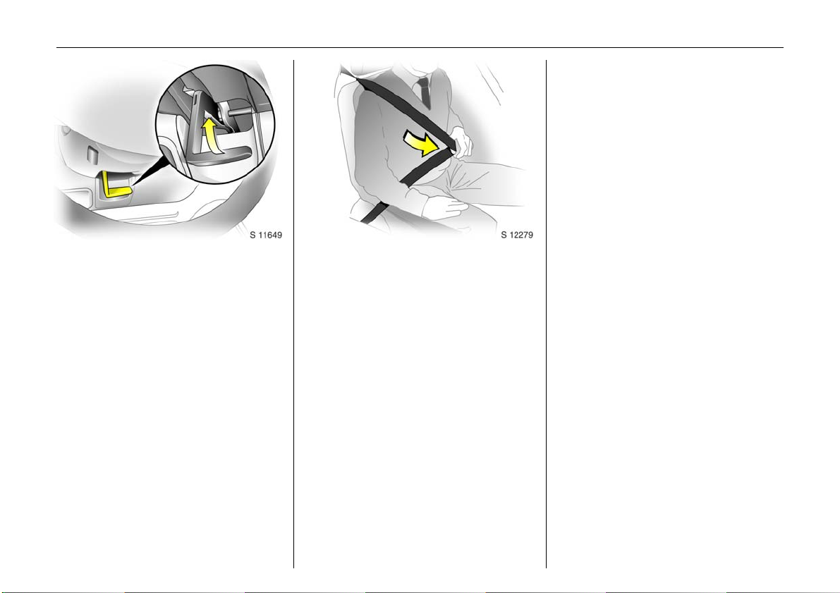
Adjusting head restraint height:
hold firmly and adjust height,
then release
6 Head restraint position – see page 47,
further information, removal – see page 48.
Page 10
In brief 5
6 Seat belts – see pages 57 to 59,
airbag systems 3 – see page 61,
seat position – see pag e 47.
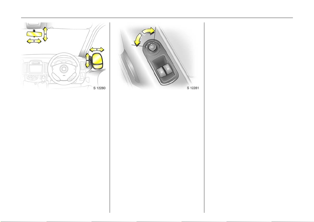
Steering wheel adjustment:
A dj u st po si tion
Adjust the steering wheel only when the
vehic le is stationary.
Move the unlocking lever upwards, adjust
th e w he el to th e d e si r e d po s iti on, th e n
release the lever.
Push the lever firmly downwards to ensure
that the whe el is locked in position.
6 Airbag sy stems - see page 61.
Fitting seat belt:
Draw seat belt smooth ly from
inertia reel, guide over shoulder
and eng age in b uckle
The belt must not be twisted at any point.
The lap belt must lie snugly against the
body. The backrest must not be tilted back
too far (recommended tilting angle
approx. 25°).
To release be lt, press red button on belt
buckle.
Page 11
In b rief6
Turn switch to right: switch operates righthand mirror.
Switch in central position: mirror
adjustment is off.
The lower aspherical mirrors are not
adjustable.
Adjust interior 3 and exterior
mirro rs:
Swive l to ap prop riate po sition
Move lever on underside of interior mirror
housing to reduce dazzle at night.
6 Further information - see page 74.
Electrically adjustable exterior
mirrors 3:
Switch in door panel
Operational with the ignition on or off.
Turn switch to left: switch operates left-
hand mirror.
Page 12
In brief 7
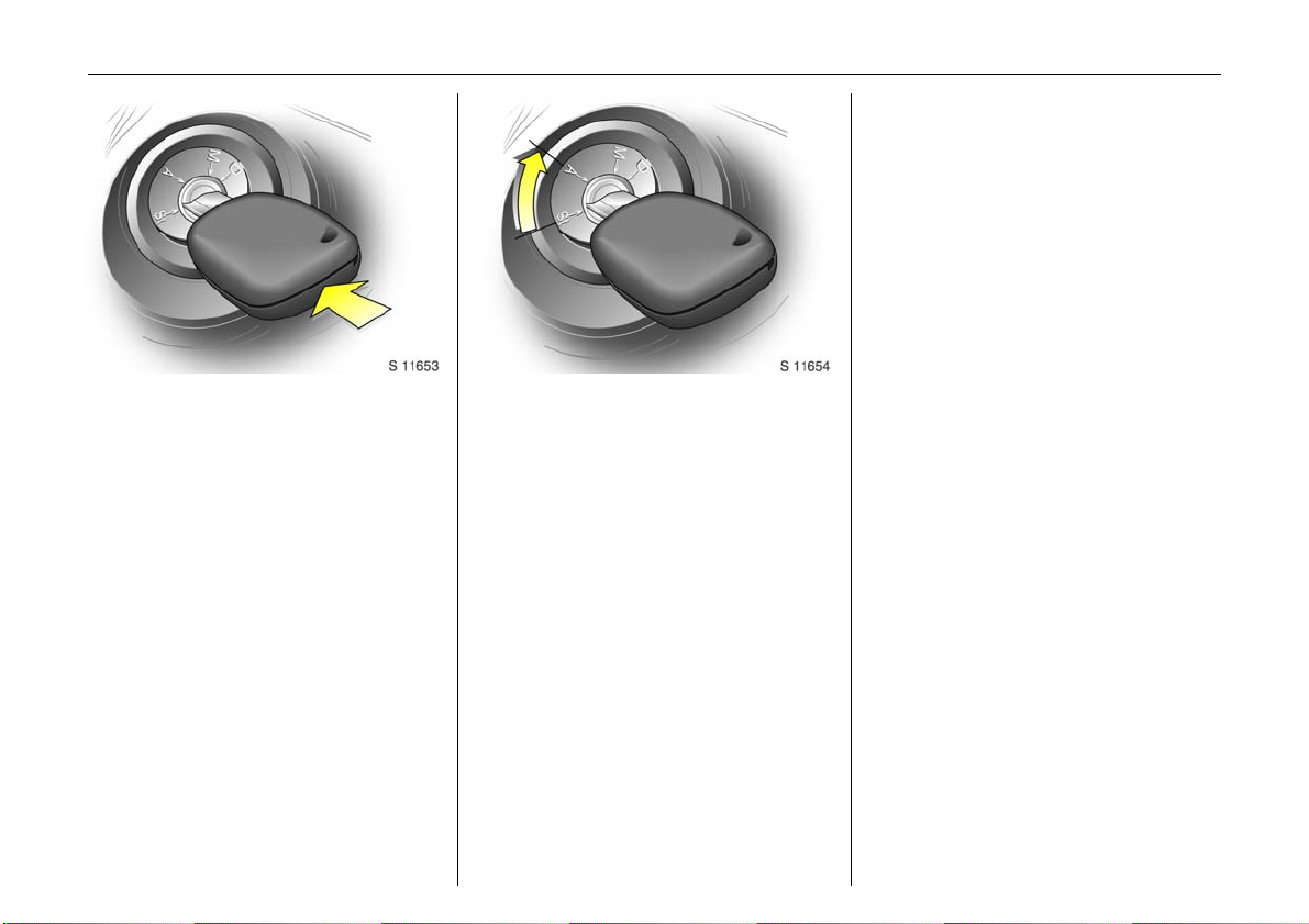
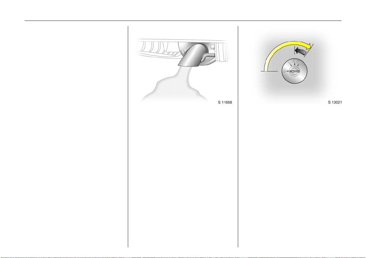
Starter switch:
Diesel engine
St = Ignition off
A = Steering unlocked, ignition off
M = Ignition on: preheat (page 17)
D = Start - (transmission in neutral)
Petrol engine
St = Ignition off
A = Steering unlocked, ignition off
M = Ignition on
D = Start - (transmission in neutral)
6 Electronic imm obilizer - see page 38.
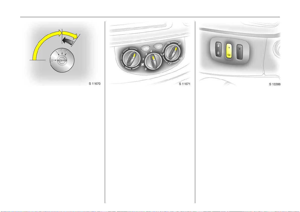
Re lea sing the stee r ing co lumn
loc k:
To release the lock,
move steering wheel slightly
and turn key to position ‘A’
6 Remove key a nd lock steering wheel - see
page 18.
Page 13
8In brief
Page 14

In brief 9
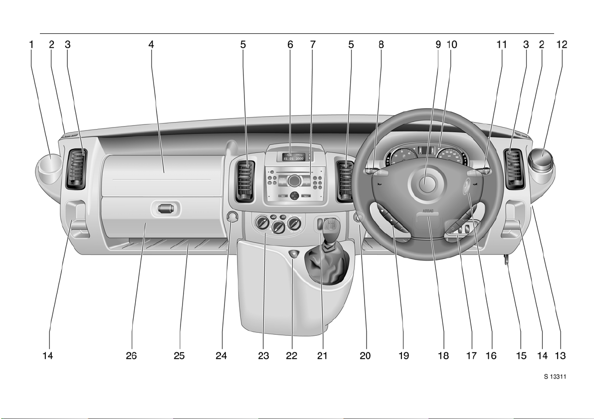
Page
1 Drink holder ........... .... ..... ........ ......... ..55
2 Door window defroster vent........... .. 83
3 Side ve ntila tion jets ... ..... ........ ......... ..83
4 Passeng er airbag 3 .. ......... .... ......... ..6 1
5 Cen tre v entilation je ts.... ........ ......... ..8 2
6 Triple information display 3 . ..... ...... 29
Graphic information display 3 ........ 31
Colour information d isplay 3 ......... ..3 1
7 Radio 3, Infotainment system 3 ... .. 35
8 Stalk for
Parking lights, headlights flash,
fog lights dipped and main beam, 12
turn signal lights .... .... ..... ............. .... .. 1 3
9 Driver’s airb ag . .............. .... .... ..... ......61
Horn . .... ......... .... ......... ......... ......... ......13
10 Instruments... .... ..... ......... ........ ..... ...... 20
11 Stalk for windscreen wiper
and wa sh system .............. .... ......... ..14
Trip computer 3........ ..... .... ......... ...... 2 6
12 As htray .... ......... ......... ......... ......... ...... 55
Pa ge
13 Fuse box ...... ..... .... ......... ......... ......... 137
14 Coin tray
15 Bonnet release lever . ............. .... ..... .. 46
16 Starter switch ... ......... ........ ......... ......... 7
17 Switches for
headlight range adjustment .......... .. 7 6
ESP
(Electronic S tab ility Program) 3 .... 1 06
Park pilot 3 . ......... ......... ......... ......... 107
18 Steering wheel adjustm ent lev er ....... 5
19 Radio/infotainment controls 3 ....... 35
20 Cigarette lighter .. ......... ......... .... ....... 5 4
21 Switches for
central locking 3 .................... .... ..... .. 41
heated rear w indow 3.. .... ......... ....... 87
Te cs hi ft 3 winter and laden
prog ra mme .......... ..... .... ......... ......... .. 91
22 Hazard w arning switch ......... .... ....... 13
23 Heating and ventilation controls .... 81
Rear air conditioning 3 ......... .... ....... 86
24 Utility hook
25 Storage tra y
26 Glove co m partment
Page 15

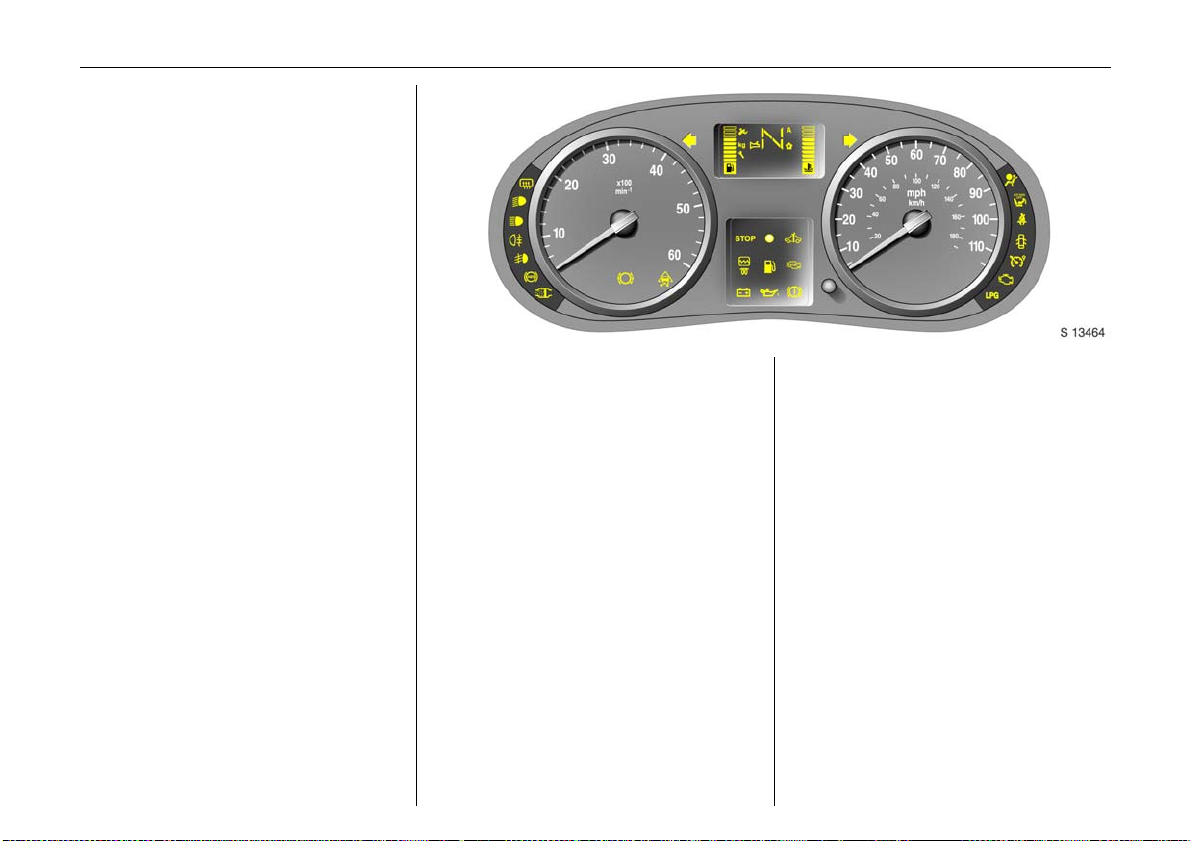
In b rief10
Control indicators
Ü Not used
9 Headlight dipped beam:
see pages 12, 75.
P Headlight main beam :
see pages 12, 75.
r Fog t ail lig ht:
see pages 12, 77.
Front fog lights 3 :
>
see pages 12, 77.
u A n ti-lo ck brak e sy s tem 3:
se e p age 115.
8 Diesel par ticle filt er 3:
se e p age 104.
F Not used
C Stop engine :
see page 21.
o Engine im mobili ser:
see pages 21, 38.
A Service 3:
see page 21.
O Turn signal lights:
see pages 13, 76.
Y Fuel level:
see page s 21, 100, 163.
ESP (Electro nic Stability
v
Program) 3:
see page 106.
Engine electronics/Preheating
D
system 3:
see page 17.
E Engine stop:
see page 21.
p Alternat or:
see page 22.
I Oil pres sur e:
see page 22.
R Brake system:
see page s 22, 151.
Airb ag systems:
v
see page 61.
Front passenger
H
airbag d eactiva tion 3:
see page 65.
Driv er’s seat belt:
X
see page 57.
Door open 3:
U
see pages 23.
U Not used
Engine electronics,
Z
Exhaust emissions:
see page 23.
Not used
B
Engine oil life monitor 3 :
F
see page 28.
Tecshift 3
Wi n ter prog ram me:
V
see page 91.
Lade n programme:
kg
see page 92.
Transmission el ectronics:
W
see page 94.
Brake pe da l app lication:
T
see page 89.
Automat ic mode:
A
see page 90.
Page 16

Lighting Heating and ventilation Windscreen wiper
7 Lig ht switch:
see pages 12, 75.
0 Parking l ights:
see pages 12, 75.
9 Dipped beam :
see pages 12, 75.
P Main beam:
see pages 12, 75.
Front fog lights 3 :
>
see pages 12, 77.
r Fog t ail lig ht:
see pages 12, 77.
O Turn signal lights:
see pages 13, 21.
¨ Hazard warning flashers :
see page 13, 76.
? Hea dlight range adjustment:
see page 76.
x Fan switch:
see page 82.
Air distribut ion:
see page 81,
M to head area
L to head area and to foot area
K to foot area
J to hea d area and to demister
V to demister
Ü Heated rear windows a nd
mirrors 3:
see page s 17, 87.
A.C
Air conditioning system 3:
see page 85.
4
Air circulat ion:
see page 85.
Stalk positions:
see page 14,
K Timed interval wipe or automatic
wiping with rain sensor 3
1
Slow
2
Fas t
n Windscreen wash
e Tailgate window wiper 3
f Tailgate window wash 3
Miscellaneous
j Horn:
see page 13.
/
Bonnet:
see page 46.
) Cigaret te lighter:
see page 54.
e/U Central l ocking 3:
see page 41.
: Glove compartment cooler 3:
see page 86.
E Park p ilot 3:
see page 107.
In brief 11
Page 17
In b rief12
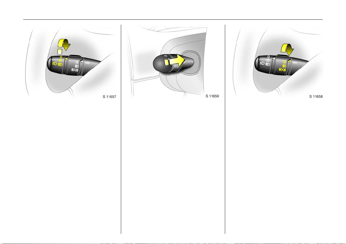
Light switch:
7 =Off
0 = Parking lights
9 P = Dippe d or main beam
6 H eadlight wa rning de vice - see page 18,
further information - see page 75,
Automatic dipped beam activation 3
- see page 76,
headlig ht range adjustment - see page 76,
headlig hts when driving abroad
- see page 78,
daytim e running lights 3 - see page 75.
Dipped a nd mai n beam :
Head light flash:
Pull stalk towards steering wheel
To change the headlight beam, pull the
sta lk tow ards th e s tee rin g w heel, th en
re lease when a click is felt.
Pulling the stalk towards the ste ering wheel
to the first stop operates the headlight
fl as h .
Fog lights:
7 =Off
> = On (front fog lights 3 only)
>r = On (front fog lights 3 and
fog tail light)
The fog lights will only illum ina te when the
ignition and headlig hts are switched on.
Page 18
In brief 13
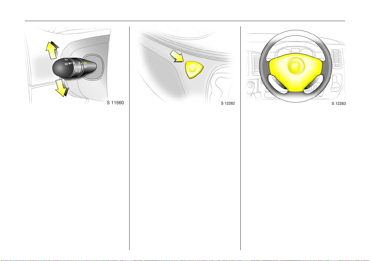
Turn signal lights:
stalk in rest po sitio n
Upwards = Right turn
Downwards = Left turn
When the stee ring whee l is turne d back, the
stalk automatically returns to its original
position. This will not happen when making
a m inor s t ee ri ng man oeuvr e s uch as la ne
changing.
When lane changing, move stalk part way
to first stop. When re leased, stalk will
spring back.
For operation of the turn signal lig hts when
towing - see pages 20 and 122.
Hazard warning flashers:
On = Press button ¨
Off = Press ¨ again
When the hazard warning system is
actuated, the button's control indicators
flash in unison with the turn signal lights.
Horn:
Press any part of the steering wheel centre
to activate the horn.
Page 19
In b rief14
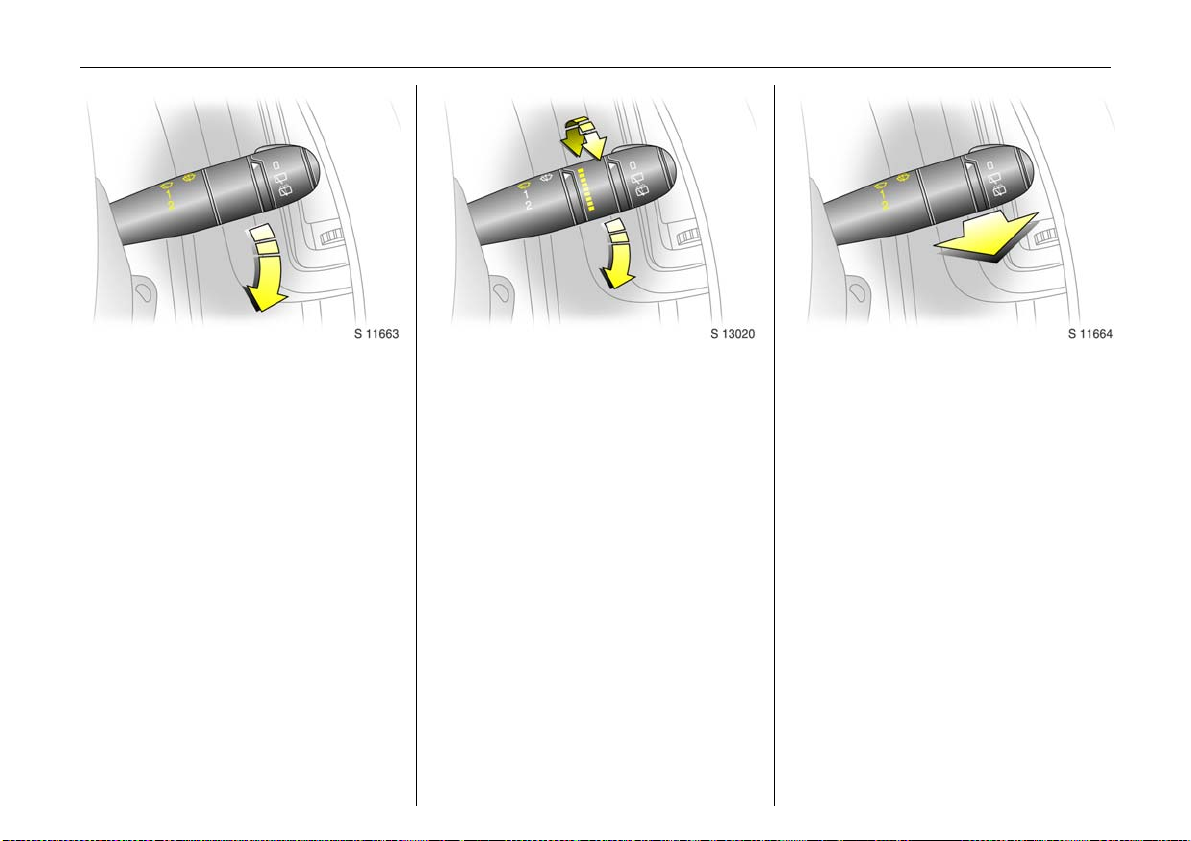
Windscreen wiper:
Move stalk downwards
K =Timed interval wipe
1 =Slow
2 =Fast
Return the stalk to its original position to
turn off.
Automatic wiping with
ra in se nsor 3:
Mo ve stalk dow nwa r ds
K = Automatic wiping with
ra in se nsor
1 =Slow
2 =Fast
The rain sensor detects the amount of
water on the windscreen an d automa tica lly
regulates the wind scre en wipe r frequ e ncy .
The sensitivity of the system can be
adjusted by rotating the variable wipe:
Less sensitive = rotate down
More sensitve = rotate up
Upon starting the engine, autom atic
wiping will need to be reselected.
6 Further information - see pages 153, 158.
Windscreen wash system:
Pull stalk towards steerin g wheel
Short pull
Th e wiper ope rates fo r one c ycle.
Long pull
Wash fluid is sprayed onto the windscreen,
at the same time the wiper operates for
four cycles.
Check regularly that the wind screen wash
system is operating efficiently.
O n ve hi cle s w ith rai n se ns o r 3, keep the
senso r area clean.
6 Further inform ation - see page 153.
Page 20
In brief 15
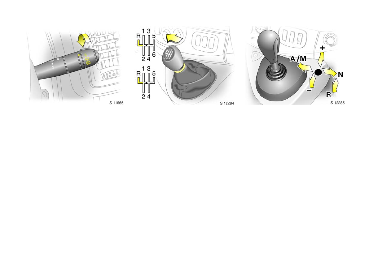
Back doo r and tailgate window
wash wipe system 3 :
Rotate switch
0=Off
e =Wiper
f =Wash
Wash fluid is sprayed onto the window
when the stalk is moved to the second
position. The switch is spring loaded and
will return to the ’wiper’ position whe n
released.
Check regularly that the window wash
system is operating efficiently.
6 Further information - see page 153.
Manual transmission:
o =Neutral
1 to 5/ 6= 1st to 5th or 6 th 3 gear
R=Reverse gear
Wh e n shift ing up f ro m 4 th to 5t h ge ar,
pressure mu st be ex erte d towards the right
at the beginning of the shift operation.
When shifting from 5th to 4th gear, do not
exert any force towards the left.
Reverse gear: with vehicle stationary,
declutch, pull up c ollar and move shift lever
to the left against resistance.
If the gear does not engage: with lever in
neutral, release clutch pedal and depress
again, then repeat gear selection.
Tecshift 3:
N=Neutral
o = Centre position
- = Shift to lower gear
+ = Sh ift to higher gear
A/M = Switch between
automatic or manual
mode
R=Reverse
The selector lever must be moved in the
appropriate direction as far as it will go.
Upon release, it automatically returns to
the centre position. Pay heed to the
gear / mode indicator in the transmission
display.
6 Further inform ation - see page 89.
Page 21
In b rief16
Before driving check:
z Ty re pressures and condition.
z Engine oil level and fluid levels in engine
com partment (see pages 145 to 148).
z All windows, mirrors, exterior lighting
and num ber p la tes free from dirt, s now
and ice and operational.
z Objects are securely located and will not
be thrown forward in the event of
sudden braking.
z Seats, seat belts and mirrors correctly
adjusted.
z Bra ke operation.
Exhaust gases are poisonous
Exhaust gases contain carbon monoxide,
wh ich is e xtrem ely po ison ous b ut h as no
od our or colour.
Therefore, never inhale exhaust gases, and
never run the engine in an enclosed space.
You should also avoid driving with the
doors open, as exhaust gases could enter
the passenger compartment.
6 Exhaust gas - see page 105.
Starting, petrol engine:
Tran smission in neutral
Depress clutch
Do not accelerate
Turn key to D
Th e incre ased engine spe ed a utomatica lly
returns to normal idling speed as the
eng ine tem peratu re rises.
6 Electronic im mobilizer - see page 38,
further information - see pages 96, 97, 99.
Page 22
In brief 17
Starting, diesel engine:
Transmission in neutral
Depress clutch
Do not accelerate
Turn key to M
When preheating control
indicator goes out 1),
turn key to D
6 Electronic imm obilizer - see page 38,
further information - see pages 96, 97, 99.
1)
Preh eating system switch es on only if o utside
temperature is low .
Drying misted-up or iced-up
windows:
Set the temperature switch to red
and fan to position 4,
set air distribution to V
Close centre ventilation jets; open side
ventilation jets and direct them towards
the door windows.
6 Heating, ventila tion - see page 81,
air conditioning system - see page 85.
Heated rear windows 3,
heated exterior mirrors 3
Press Ü =On
Press Ü a gain= Off
6 Further information - see page 87.
Page 23
In b rief18
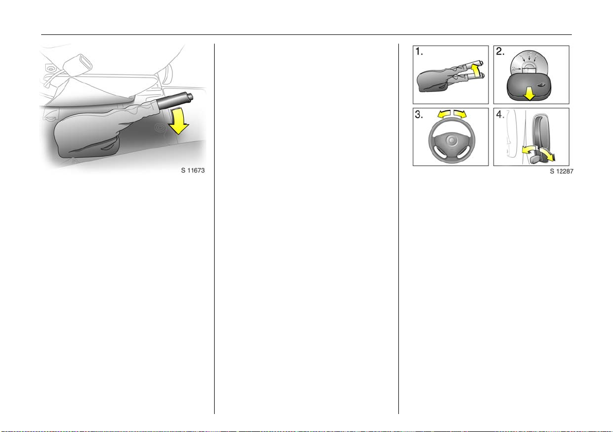
Releasing the hand brake:
Raise lever slightly,
press lock bu tton,
lower lev er fully
Drive carefully, economically and with the
environment in m ind. While driving, do not
do anything that could distract you.
Warning b uzzers
While driving:
z O perating the indicators.
z Illumination of low fue l control ind icator.
z Tecshift 3, high c lutch te mpe ra ture .
z Se at belt not fastened 3.
When the vehicle is parked and driver’s
door is opened:
z Headlights switched on.
z Tecshift 3: neutral not selected, foot
brake not depressed or handbrake not
applied.
6 Driving hints - see page 95,
Save fu el, prote ct the environ ment - s ee
page 97.
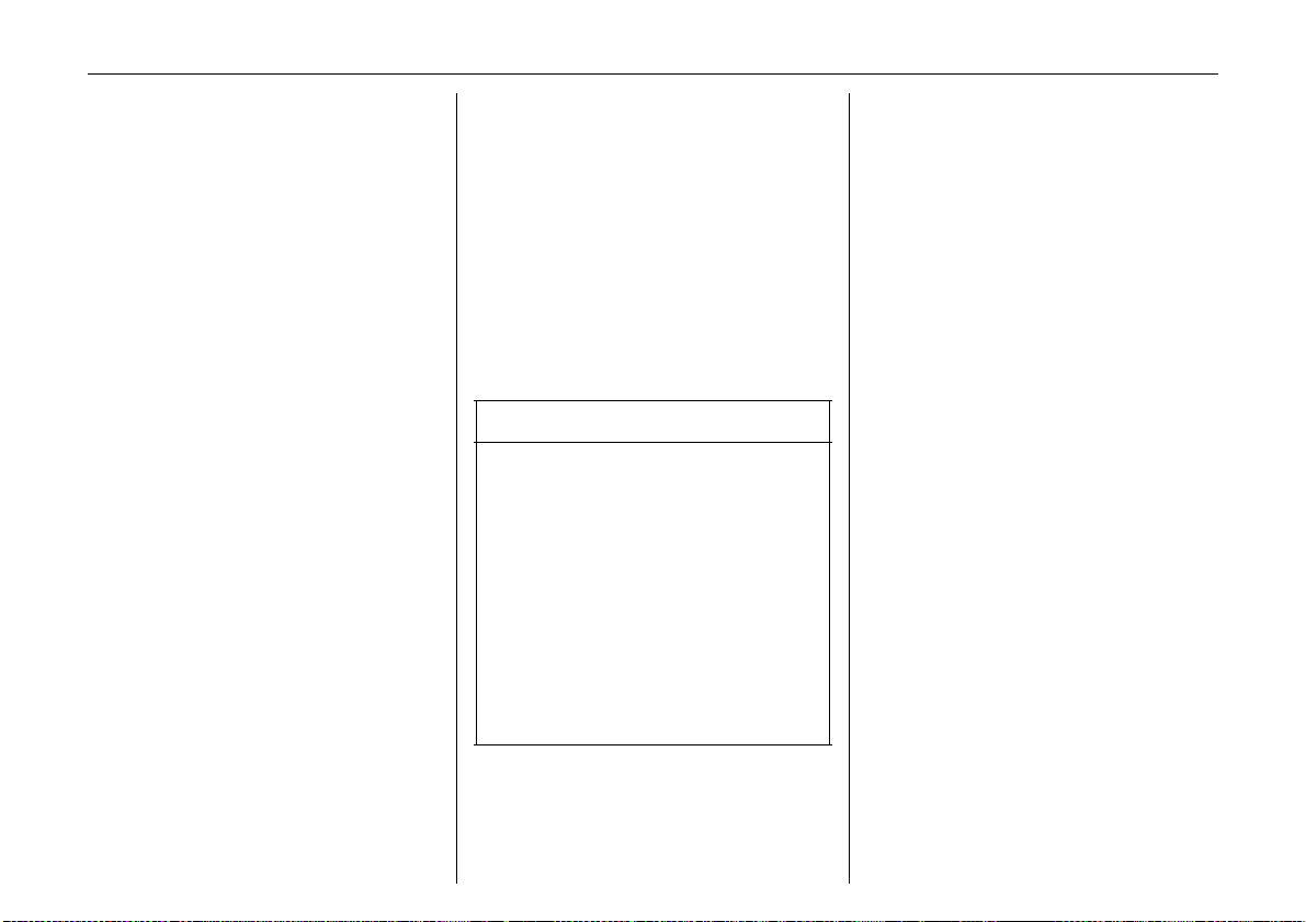
Parkin g the vehicle:
Apply hand brake firmly
Close windows
Switch off engine
Remove key
Engage steering wheel lock
Lock doors
6 Further information - see pages 38, 96,
remote control - see page 39,
central locking system - see page 41,
Vauxhall alarm system - see page 43.
Page 24
In brief 19
Advice when parking:
z Always apply hand brake firmly. Engage
first gear or reverse ge ar. On slopes
apply the hand brak e as far as it w ill go.
z Turn steering wheel until lock is felt to
engage (anti-theft protection).
z Switch off exterior lights, otherw ise the
headlight warning device will sound
whe n th e driver’s door is opened.
z Cooling fans may run on after the engine
has been switched off.
z Do not park vehic le on easily ignitable
surfaces as th e hot ex ha us t s ys tem could
cause the surface to ignite.
Service work, maintenance
We recommend that you entrust all work to
your Vauxhall Authorised Repairer, who
can provide you with reliable service and
correctly perform all work according to
factory instructions.
Vauxhall Service - see page 142.
Genuine Vauxhall Pa rts and
Accessories
We recommend “Genuine Vauxhall Parts
and Acce ssories” and c onversion parts
released expressly for y our v ehicle type.
These parts have undergone special tests
to establish their reliability, safety and
specific suitability for your vehicle. Despite
continuous market monitoring, we cannot
assess or guarantee these attribute s for
other products, even if they have been
granted approval by the relevant
authorities or in some other form.
"Genuine Vauxhall Parts and Accessories"
and conversion parts approved by
Vauxhall can be ob tained from your
Vauxhall Authorised Repairer, who can
give advice about permitted technical
changes and correc t installation.
9 Warning
Carry out regularly the checks
recom mended in this Owner's Manual.
Ensure that you r vehicle is s e rv iced at th e
service intervals specified in the Service
Booklet. We recommend that you entrust
this work to your Vauxhall Authorised
Repairer.
Have faults remedied without delay!
Consult a workshop. We recommend your
Vauxhall Authorised R epairer. If
necessary, interrupt your journey.
6 Maintenance - see page s 144 to 155.
That was a brief overview of the
most imp ortan t in forma t io n for
your first drive in your Vivaro.
Your vehicle has still more
instruments and con trols,
possibly also optional
equipment.
The re ma in ing ch apte rs of the
Owner’s Manual contain
important information on
operatio n, safety and
maintenance a s well as a
complete index.
Page 25
20 Instruments
Instruments
Control indicators .... ..... ......... ........ ..... 20
Fuel gauge .. .... ..... ......... ......... ........ ..... 23
Coolant te mperature gau ge ..... ......... 24
Tra n sm ission display 3 .... ..... .... .... ..... 24
Tachome ter. .... ..... ............. ..... .... .... ..... 25
Spe ed om ete r... ..... .... ..... .... ............. ..... 25
Electronic odometer/clock 3 . .... .... ..... 25
Trip computer 3 ........... .... ..... .... .... ..... 26
Engine oil life monitor for vehicles
with diesel particle filter 3.. .... ......... 28
Triple information display 3 . ............. 29
Graphical information display 3 or
colour information displa y 3,
selecting functions ..... ......... ........ ..... 31
Radio 3............ ..... .... ..... ............. .... ..... 35
Control indicators
The control indicators described he re are
not p resent in all vehicles. The description
applies to all instrument versions.
Ü
Not used
9
Headlight dipped bea m
Lights up when dipped beam is on.
P
Hea dlight main b eam
Lights up wh e n m ain beam is on and when
headlight flash is operated.
r
Fog t ail li ght
Lights up when the fog tail light is switched
on .
>
Front fog li ghts 3
Lights up when front fog lights are
switched on.
u
Anti-lock brake system
see page 115.
8
Die sel particle filter 3
Lights up when regeneration of diesel
particle filter is required - see page 104.
F
Not used
Page 26

Instruments 21
v
ESP (Electronic S tability Prog ram) 3
see page 106.
F
Eng ine oil life monit or 3
See page 28.
kg
Tecshift L aden progra mme 3
Control indicator illuminates in
tr ansm iss ion display when L ade n
programme is e nabled - see page 92.
T
Te cshi ft foot bra ke app licatio n 3
see page 89.
W
Tecshift elec tronics 3
Lights up b riefly when ignition is switched
on. Illuminates in transmission displa y
when fault has occurred - see page 94.
A
Te cshi ft autom atic mode 3
Control indicator illuminates in
transmission display when automatic
mode is selected - see page 90.
V
Tecshift W inter progra mme 3
Control indicator illuminates in
tr ansm iss ion display when W inter
programme is e nabled - see page 91.
O
Turn sig nal lights
Flashes when turn signal lights are on.
Flashes rapidly: a turn signal bulb has
fa il e d.
An audible warning can be heard when the
turn signal lights are on. When towing a
caravan or trailer, the pitch of the audible
warning changes.
C
Stop e ngin e
If C lights up in conjunction with p, I,
E or R, stop engine imme diately and
consult a workshop. We recommend your
Vauxhall Authorised Repairer.
o
Engine im mobili zer
If the indicator flashes when the ignition is
on, there is a fault in the immobilizer
system; the engine cannot be started - see
page 38.
A
Service / engine electronics 3
If A lights up in conjunction with u or v,
interrupt your journey. C onsult a workshop.
We rec ommend your Vauxhall Authorised
Repairer.
D
Prehea ting/Fuel filter/Engine electronics
Lights up briefly during engine preheating.
If illuminated constantly it indicates:
z The pre se nce o f wa ter in the dies el fu el
filter 3. Drain fuel filter of residual wate r,
see page 149.
z An electronic system failure, consult a
workshop. We rec ommend your
Vauxhall Authorised Repairer.
Y
Fuel level
If it lights up: fuel level low, fill up.
Neve r let the tank become empty!
With diesel e ngines it is not possible to start
the engine after the tank has been run
empty. The fuel system must be bled fir st.
Page 27

In st rum en ts22
E
Engine stop
Will light up in conjunction with C en gine
if coolant temperature is too high. Stop
vehicle - consult a workshop. We
recommend your Vauxhall Authorised
Repairer.
p
Alternator
Lights up w hen ignition is switched on.
Goes out after engine is started.
If illuminated during driving:
Stop vehicle and switch off engine. The
battery is not being charged and the
engine cooling may be interrupted. The
brake servo unit may cease to be effective.
Interrupt your journey, consult a workshop .
We recommend your Vauxhall Authorised
Repairer.
I
Oil p ressure
Lights up when ignition is switche d on.
Goes out after a short period of time. C an
lig ht up intermittently whe n idling with hot
engine; must g o out when engine sp ee d is
increased.
If illuminated during driving:
Engine lubrication may be interrupted,
re sulting in damage to the engine and/or
locking of the driving wheels:
z Depress clutch.
z Move gear shift lever to neutral.
z Sw itch off ignition (to position A).
Considerably greater force will be
required for braking and steering.
9 Warning
Do not rem ov e ke y until ve hicle has come
to a standstill, otherwise the steering
column lock could engage unexpectedly.
Consult a workshop. We recommend your
Vauxhall Authorised Repairer.
R
Brake system
Lights up when ignition is switched on if
hand brake is applied and/or fluid level for
brake hydra ulics is too low.
9 Warnin g
If it l ights up wh en the ha nd brake i s no t
applied: stop vehicle; interrupt your
journey immediately. Consult a
workshop. We recom mend your Vauxhall
Authorised Repairer.
6 Further information - see page 113.
v
Airb ag 3
see page 61.
H
Front pass enger airba g deactivation 3
Lights up when the ignition is switched on
and remains illuminated when the front
passenger airbag has be en deactivated.
If H illuminat ed in con junction w ith v or A
consult a workshop. We recommend your
Vauxhall Authorised Repairer.
6 Further information - see page 65.
Page 28
X
Driv er’s seat b elt
Lights up whe n ignition is switch ed on and
if driver’s seat belt is not engaged.
Seat belts, see page 57.
U
Door open 3
Operational only when ignition is switched
on . Lights up when drive r’s, passenger’s or
side loading doors are open.
U
Not used.
Z
Exhaust em issions 3
Control indicator lights up whe n ignition is
switched on. Goes out shortly after engine
sta rts.
If it lights up when the engine is running:
Fault in emission control system. The
permitted emission limits may be
exc eeded. Con sult a worksh op. We
recommend your Vauxhall Authorised
Repairer.
If it flashes when the engine is running:
For fault that can lead to destruction of the
catalytic converter, see page 102. Consult
a workshop immediately. We recommend
that you consult your Vauxhall Authorised
Repairer.
B
Not used
Instruments 23
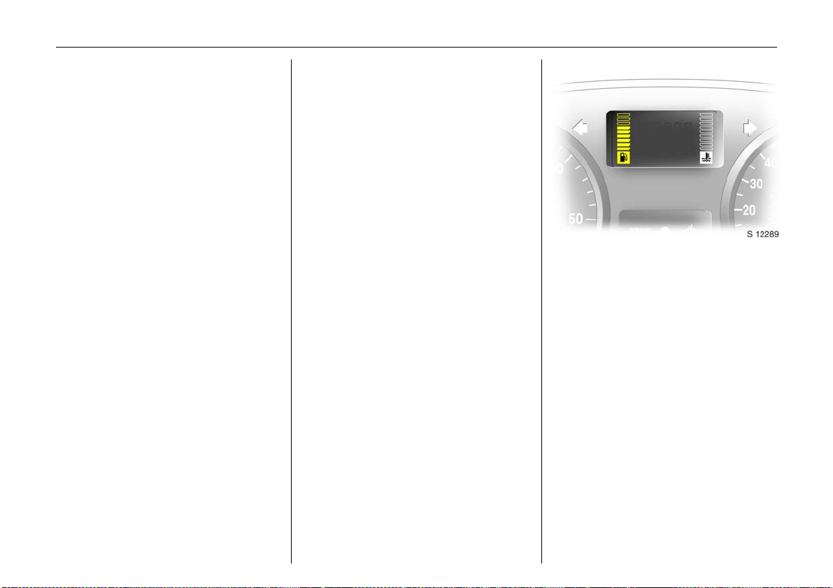
Fuel gauge
Display of fuel level:
Illumination of bars displays fuel level.
When gauge indicates fuel supply low, fuel
warning Y illuminates = fill up.
See page 99.
Neve r let tank becom e empty!
Page 29
In st rum en ts24
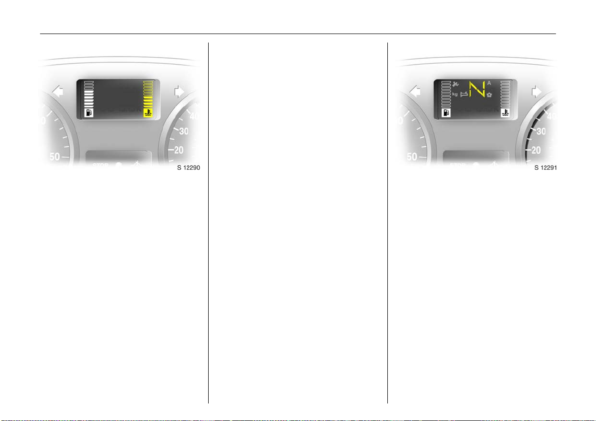
For physical re asons, the coolant
temperature gauge shows the coolant
temperature only if the coolant level is
adequate.
Coolant temperature gauge
Display of coolant temperature:
Bars illum inate d
in lower area
Bars illum inate d
up to central
area
Bars illum inate d
into uppermost
zone
or indicator E
illuminates 3
= Engine operating
tempera ture not yet
reached
= Normal operating
temperature
= Temperature too
high. Stop vehicle,
switch off engine.
Danger to engine.
Che ck c oolant level
immediately. See
page 150.
Tran smission display 3
Display of the selected gear and mode with
Tecshift 3.
N Neutral or idling position.
R Reverse gear.
A Automatic mode.
kg Laden prog ramme .
V Win ter pro gramm e.
T Foot brake application.
W Transmission electronics.
Page 30
Instruments 25
Tachometer
Making use of the tachometer helps to
save fuel; it indicates the engine speed in
revolutions per m inute.
Warning zone on right: maximum
pe rmissible engine spe ed exc ee ded,
danger to engine.
If possible, d rive in each gear in the low
engine speed ran ge (between app rox .
2000 and 3000 rpm) and maintain an even
vehicle speed.
Speedometer
Indicates the vehicle speed.
Certain vehicle variants feature a speed
re g u la t or 3 1) which restricts the vehicle
maximum speed. As a visible indica tion of
this, a warning label is located on the
instrument panel.
Depending on driving environment (e.g. when
descending steep inclines) the vehicle speed
can exceed set limits. In such insta nces it
rema ins the d river’s responsibility to adhere to
the specific speed limits.
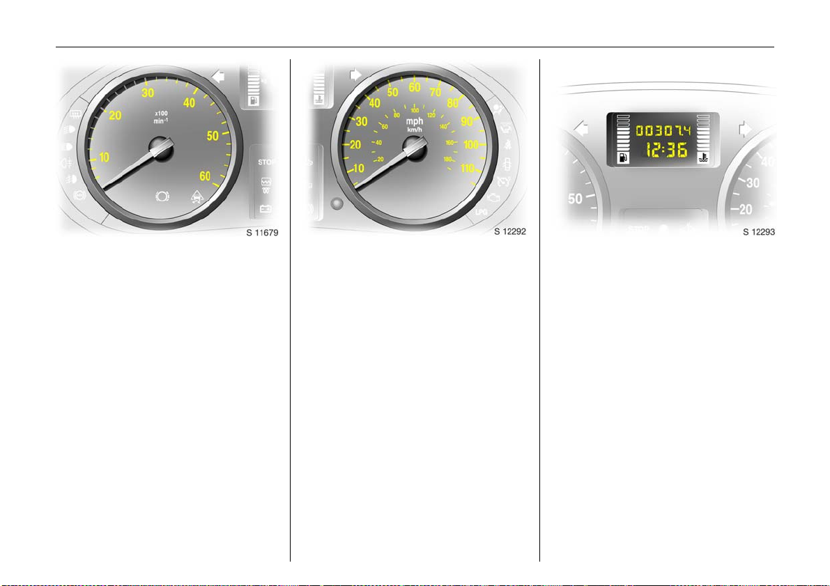
Electronic odom eter/clock 3
Norm al m ode :
Th e od om ete r and clock a re v is ible .
Reset:
The reset button is loc ated alongside the
speedome ter. Pre ss b uttton once to display
the trip odometer.
Press the button and hold, the display will
flash and after 1 second will reset to z ero.
Press the button again to return the
odometer to normal mode.
Clock adjust mode:
With the d isplay in normal mode press and
hold the button, and the minutes reading
will begin to increase.
After the button is released the clock will
continue to flash for a further 5 seconds to
enable further adjustments to be made.1)
Page 31

In st rum en ts26
Trip computer 3
In addition to the electronic odometer
fu nc tio n s , th e tr i p com p u ter c a n al so
display a dditional monitored vehicle data;
z Fuel used ,
z Average consumption,
z Instantaneous consumption,
z Range,
z Distance tra velled,
z Average speed.
Pressing the selection switch located on the
end of the windscreen wash control stalk
will cycle through these displays.
Fuel used
Displays the amount of fuel consumed
since the last reset. The measurement can
be restarte d at any time – see pag e 28.
Average consumption
Is displayed, taking into consideration the
distance travelled and the fuel used since
th e last reset. Th e mea surem ent can be
restarted at any time - see page 28.
Page 32

Instruments 27
Instant aneous consumption
The value is displayed after reaching a
speed of 15 mph (25 km/h).
Range
The range is calculated from the current
contents of the fuel tank and the average
consumption since the last reset
- see page 28.
Distance travelled
Displays the distance driven since the last
reset. The measurement can be restarted
at any time.
Page 33

In st rum en ts28
Ave rag e sp eed
Th e average speed is displaye d, since th e
last reset. The measurement can be
restarted at any tim e.
Stoppages in the journey with the ignition
off are not included in the calc ulations.
Reset current t rip com pute r informa tion
The following trip computer information
can be reset:
z Fuel used,
z Average consumption,
z Range,
z Distance travelled,
z Average speed.
To reset the trip computer, select one of its
functions then press and hold the reset
button, the display will flash and after 1
second will reset.
Interruption of p ower supply
If the power supply has been interrupte d or
if the battery voltage has dropped too low,
the values stored in the trip computer will
be lost.
Engine oil life monitor for vehicle s with
di esel par ticle filt er 3
Each time the ignition is switched on, the
remaining distance before the next engine
oil and filter change is due will be shown in
the display for approx. 5 seconds.
Within 1 800 miles (3 000 km) of the next
eng ine o il c han ge be ing du e, the rem ainin g
distance and F will be displayed for
app rox . 30 se cond s as a rem inde r. Mak e
an ap pointment with a workshop for
service work as soon as possible. We
recommend your Vauxhall Authorised
Repairer.
6 Further inform ation - see page 105.
Page 34

Triple info rmation display 3
Display for time, outside temperature,
radio/date.
When the ignition is off, the time, date and
outside temperature can be made to
appear for approx. 15 seconds by briefly
pressing one of the two buttons beside the
display.
Settin g d ate and t ime
Switch off radio. Press Ö and ; beside
display as follows:
Pre ss Ö for approx. 2 seconds:
Day flashes
;:Set day
Ö:Month flashes
;:Set month
Ö:Year flashes
;:Set year
Ö:Hours flash
;:Set hours
Ö:Minutes flash
;:Set minutes
Ö: Clock starts at 0 seconds.
Instruments 29
If only the time is to be set, repeatedly
press Ö with display in setting mode until
hours/minutes flash.
Autom atic date and t ime set ting 3
Possible in the case of radio reception from
RDS stations1) which broad cast a time
signal.
Automatic setting is carried out once the
radio has been switched on and a RDS tim e
signal has been received. The setting is
indicated by } in the display. If no time
signal is received, or the tim e signal is
inaccurate, the date and time must be set
manually.
Deactivating and ac tiv ating the automatic
setting function (e.g. if an inaccura te time
signal is received from the broadc asting
station):
Press Ö for ap prox. 2 seconds; the tim e
display is now in setting mode.
Press Ö twice (until year flashes).
Press Ö for approx. 3 seconds until } in
d isplay flash e s a nd the dis play
“RDS TIME” appears (years
flash while button is depressed).
Press ; Display indic ates:
RDS TI ME 0 = Deactivated
RDS TI ME 1 = Activated
Press Ö three times.
1)
RDS = Radio Data System.
Page 35

In st rum en ts30
Fault display
Display --.-°C or an F in the display
indicates a fault. Have the cause
eliminated, c onsult a workshop. We
recommend your Vauxhall Authorised
Repairer.
Interruption of power suppl y
If the power supply has been interrupted or
if the b attery voltage has dropped too low,
the date and time must be reset.
When the battery has b een reconnected or
charged, set the date and time as
described under “Setting da te and time”.
In the case of radios with RDS 3, the time is
set automatically when the radio is
receiving an RDS station which broadcasts
a time signal (see page 29).
Outside temperature
A fall in temperature is indicated
immediately and a rise in temperature
after a time delay.
9 Warning
Caution: The road surface ma y already
be icy even though the display indicates
a few degrees above 0 °C.
If the external tempera ture falls to 3 °C, to
warn of ice on the road the symbol :
appears on the Triple Info display.
When the temperature climbs, the symbol
: goes out above 5 °C.
Sl ippery road
-2,5°C
OK
In vehicles with graphical information
display 3 or colour information d isplay 3, a
warning m essage appears in the display as
a warning for icy road surfaces. There is no
message below -5 °C
9 Warnin g
Caution: The road surface may already
be icy even though the display indicates
a few degrees ab ove 0 °C .
Page 36

Instruments 31
Gr a ph i ca l informa tion d is play 3
or colour information display 3,
selecting functions
Functions and their menus are depicted in
the graphical information display and
colour information display.
Th ese fun ctions are m arked or e xecute d in
the menu display via the cross switch, the
multifunction knob 3 on the Infotainm ent
System or buttons 3 on the steering wheel.
To select with four-way button:
Select menu item s via menus and
with the buttons/four-way button of
the Infotainment system.
Selection with the multifunction knob 3:
Tu rn Mark menu items
or commands, select
functions.
Pre s s Select marked item,
confirm command.
To exit a menu, turn the multifunction
button left or rig ht to Return or Main
and selec t.
Selec tion using buttons 3 on s tee ring
wheel:
Select menu options via menus and
with the buttons.
Page 37

In st rum en ts32
FM AS [TP] REG C Din MP3
90.6
MHz
19,5° 19:36
For each functional area the re is a main
page (Main), which is selected at the top
edge of the display (not with the
Infotainment system CD 30 or the
Mobile Phone Portal):
z Au dio
z Navigation 3
z Te le ph o ne 3
Function areas audio, navigation 3 and
telephone 3 – see Infotainment System
Ins tructions.
7 Settings 19,5° 19:36
Time , Date 19:36
Language
Units 10 . 07 . 2004
Con trast
Day / Night
6 Ign. logic
System setting s
The settings are a ccessed via the Settings
menu.
Pre ss th e Main button 3 (not found on all
Infotainment systems) on the Infotainment
system (call up main display).
Pre ss th e Settings b utton on the
In fotainment system. F o r In f ota in me n t
sy ste m CD 30 , no m en u may be select e d.
Th e Setti ng s menu is displayed.
7 Ti me, Date 19,5° 19:3 6
Time 19:36
Date 10 . 07 . 2004
6 Synchron. clock automatical.
Sett ing dat e a nd time
Selec t menu item Time , Da te, from the
Sett ings me nu.
The menu for Time, Date, is display ed.
Selec t the menu items required:
Make the desired se tting.
Correcting time 3
Som e RDS transmitters1) do not send
correct time signals. If the incorrect time is
frequently displayed, deactivate
automatic time synchronisation 3 and set
the time m anually.
To correct time with the he lp of RDS, sele ct
menu item Synchron. clock automat ical.
from the Time, D ate , menu.
1)
RDS = R adio Data System.
Page 38

Instruments 33
7 Settings 19,5° 19:36
Time , Date
Language Deutsch
Units English
Contrast Español
Day / Night ...
6 Ign. logic
Language selection
You ca n select the display language for
some functions.
Select menu item Language from the
Setti ng s menu.
The a vailable languages are displayed.
7 13 Languages 19,5° 19:36
X Deutsch
English
Español
Dutch
French
Italiano
Select the desired language.
Selections are indicated by a 6 in front of
the menu item.
In sy ste ms wit h voi ce outpu t 3, wh en the
language setting of the display is changed
the system will ask whether the
announcement language should also be
changed – see Infotainment system
instructions.
7 Settings 19,5° 19:36
Time , Date
Language
Units
Con trast
Day / Night
6 Ign. logic
Setting units of measure
You can select which units of measure are
to be used.
Selec t menu item Units from the Se ttings
menu.
The available units are displayed.
Selec t the desired unit.
Selec tions are indicated by a o in front of
the menu item.
~ E urope-SI
| Japan
| Great Britain
| USA
Page 39

In st rum en ts34
7 Contrast 19,5° 19:36
12
Adjusting contrast 3
(graphi cal information di splay)
Select menu item Contra st from the
Setti ng s menu.
The menu for Contra st is displayed.
Confirm the required setting.
Settin g d isplay mode 3
The display c an be adapted to light
conditions: Dark coloured text on a light
background or light coloure d text o n a
dark background.
Select menu item Day / Night from the
Settin gs menu.
The options are displayed.
Automatic: Adap ted b ased on vehic le
lig hting.
Always day design: Dark coloured te xt on
lig ht background.
Alway s night de sign: light coloured text on
dark background.
Selections are indicated by a o in front
of the menu item.
Ign. log ic 3
See Infotainment system instructions.
Ü 19,5° 19:36
00:00:00
Timer
Start
Reset
Options
St op wa tch 3
Press BC b utton on the infotainment
system
The Ti m er menu is display ed.
To start, select menu item Start.
To re set, s ele ct me nu ite m Reset.
Page 40

Instruments 35
The stop watch information to be
displayed can be selected via menu
Options 3:
Driv ing Time excl. Stop s
Measurement of the time the vehicle is in
motion. Stationary time is not included.
Driv ing Time incl. Stops
Measurement of the time the vehicle is in
motion. The tim e the vehicle is stationary
with the key in the starter switch is
included.
Travel Ti me
Measurement of the tim e from manual
activation v ia Start to manual deactivation
via Reset.
Radio 3
The radio is operate d as describ ed in the
operating instructions supplied.
Vehicle radio reception will differ from that
ob tained with domestic radios.
As the v ehicle antenna is relatively near the
ground, the broadcasting companies
cannot guarantee the same quality of
re ception as is obtained with a dome stic
ra dio using an ov erhead antenna.
z C hanges in distance from the
transmitter,
z Multi-path reception due to reflection
and
z Shadowing
may cause hissing, noise, distortion or loss
of reception a ltogether.
St e e r in g wh eel mo unt ed remote
control 3
Radio and infotainment system functions
can be operated by the buttons mounted
on the steering wheel.
The radio 3 and infotain ment system 3 are
operated as described in the respective
operating instructions supplied.
Page 41

In st rum en ts36
Electronic tachograph 3
The tachograph is operated as described
in the operating instructions supplied.
Observe regulations regarding use.
Infotainment and navigation
systems 3
The systems are operated as described in
the operating instructions supplied.
The navigation system is supplied with a
CD or DVD detailing the local territory.
For additional countries/territories,
separate CD’s or DVD’s are available from
your Vauxhall Authorised Repairer.
Mobile te leph ones and ra dio
eq u i pment (C B ) 3
The Vauxhall installation instructions and
the opera ting guid elines provided by the
telep ho n e ma nufacturer mu s t be ob se rved
when fitting and ope rating a mobile
telephone. Failure to do so could invalidate
the v ehicle’s operating permit (EU Directive
95/54/EG).
Requirem en ts to ens ure tro ub le-free
op er at io n :
z Professionally installed exterior aerial to
obtain the maximum range possible
z Max imum transmission power 10 W
z Installation of the telephone in a suitable
spot (see note on page 66).
Obtain advice on predetermined
insta llation locations for the external
antenna and equipment hold er and ways
of using d evices with tran smission powe r of
more than 10 Watts. We recommend that
you consult your Vauxhall Authorised
Repairer, who will have consoles and
various installation kits and install them in
accordance with regula tions.
Use a hands-free attachment if you must
use your phone while driving. Even with a
handsfree attachment, the telephone
could d istract you from th e tr affic sit ua tion.
Follow the national regulations of the
country in which you are driving.
9 Warnin g
When used in the vehicle interior, mobile
telephones and radio equipment (CB)
with integrated antenna may cause
malfunctions in the vehicle electronics.
Mobile telephones and radio equipment
(CB) should only be use d with an antenna
fitted o n the vehicle ex terior.
Page 42

Keys, doors, bonnet 37
Keys, doors, bonnet
Re placem ent ke ys ... ..... .... ......... ......... 37
Door locking and unlocking.. .... .... ..... 37
Child s afety lock ...... ..... .... ......... ......... 37
Electronic immobilizer ...... ..... ............. 38
Radio frequency remote control 3.... 39
Central locking system 3.............. ..... 41
Mechanical anti-theft loc king
sy ste m 3 ... ............. ..... .... ..... ............. 43
Vauxhall alarm system 3...... .... .... ..... 43
Sliding side doors 3. ..... ......... .... .... ..... 44
Back doors 3 ........ .... .............. .... .... ..... 45
Tailgate 3 ................ ..... .... ..... ............. 45
Bonnet release ......... ..... .... ......... ......... 46
Replacement keys
The key is a constituent of the electronic
immobiliser. Ordering keys fr om a Vau xhall
Authorised Repairer guarantees problem free operation of the electronic
immobiliser.
Keep the sp are k ey accessible in a saf e
place.
Locks - see page 160.
Door locking and unlocking
From outside:
Pull the outside handle to open the front
door.
re m o te cont r o l 3 - see page 39,
central locking system 3 - see page 41,
anti-theft lock ing 3 - see page 43.
Fro m ins ide :
Pull the inside lever to open the front door.
The door can be locked or unlocked by
pushing the lock button or using the central
locking switch 3 - see page 42.
To prevent the driver from being
inad vertently locked out, the front doors
cannot be locked when they are open.
6 Further information - see pag e 2.
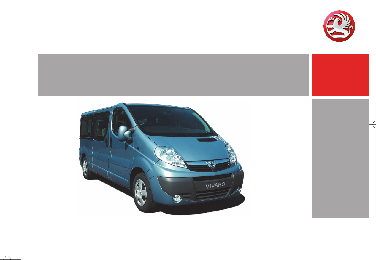
Child safety lock
The child safe ty lock for the sliding side
door 3 is located on its rearwa rd facing
edge.
9 Warnin g
Use the child safety lock whenever
children are occupying the rear seats 3 .
Disregard may lead to injuries or
endanger life. Vehicle passengers should
be informed accordingly.
To engage, turn knob from the vertical
position: anti-clockwise for right hand side
door or clockwise for left hand side door.
Door cannot then be opened from inside.
Page 43

Keys, doors, bonnet38
Not e
The immobilizer does not lock the doors.
Therefore, after leaving the vehicle , always
lock it and switch on the Vauxhall alarm
system 3.
The Car Pass contains all the vehicle’s data
and therefore must not be kept in the
vehicle.
Have your Car Pass ready to hand when
consulting a Vauxhall Authorised Repairer.
Electronic immobilizer
The system checks whether the vehicle may
be sta rted using the key that has been
inserted. If the key is recognised as
"authorised" the vehicle can be started.
The check is carried out via a transponder
housed in the key.
The electronic immobiliser is automatically
activated when the key is removed from
the starter switch.
Control i nd icator for imm obilize r
The control indicator lights up when the
ignition is switc hed on then goes out.
If the control indicator flashes rapidly after
the ignition is switched on, there is a fault in
the immobilizer system.
z Turn ignition off and remove key,
z wait a pproximately two seconds,
z then repeat starting procedure .
If the control indicator fails to extinguish,
try to start the engine using the spare key.
Obtain assistance from a workshop. We
recommend that you consult your Vauxhall
Authorised Repairer.
Page 44

Keys, doors, bonnet 39
C entra l locking system 3
see page 41.
Mechanic al anti -theft locking system 3
see page 43.
Vauxhall alarm system 3
see page 43.
Radio frequency remote control 3
The remote control is used to operate the
central locking system 3.
Dep ending on model the vehicle may use a
two or three function remote control.
The remote control has a range of approx.
3 metres. The range may be reduced
owing to shadowing and reflection of the
radio waves. To operate the remote
control, direct the remote control unit a t
th e v ehicle.
For your convenience we recommend that
the central lock ing system is alway s
operated using the remote control unit.
Tre at the remote control unit with care; it
should be protected against moisture and
should not be operated unnecessarily.
Page 45

Keys, doors, bonnet40
Note
If the central locking system 3 cannot be
operated with the remote c ontrol, this may
be due to the follow ing reasons:
z The remote control is out of range.
z The battery voltage of the remote
control is too low. Change the battery in
the remote control unit.
z The remote control has been operated
too many time s in succe ss ion ou tside the
vehicle’s reception range (e.g. at too
great a distance from the vehicle).
The remote control must b e
re programmed, we recomme nd your
Vauxhall Authorised Repairer.
z Inte rference from h igher p ower radio
waves from other sources.
Loc k or unloc k the doors manually using
the key or central locking switch. Ma nual
locking does not operate the central
locking system. Have cause of fault
rem edied. We recommend that you consult
your Vauxhall Authorised Repairer.
Changing the battery in re mote control
uni t
Replace the battery in accord ance with the
Service Booklet or when the range of the
remote control starts to become reduced.
Tw o function remote control unit:
Open the battery compartment by
inserting a coin into the slot and twisting.
Ensure the new batte ry is installed
correctly.
Replace the cover a nd press until it is fully
engaged.
Thre e func tion re mote control uni t.
Open the battery compartment by
removing the screw on the rear cover, then
inserting a coin into the slot and twisting.
Ensure the new battery is installed
correctly.
Replace the cover and press until it is fully
engaged, then replace and secure screw.
Make sure that you dispose of old batteries
in accordance with environmental
protection regulations.
Page 46

Central locking system 3
For front, side and b ack doors 3, tailgate 3
and fuel filler flap 3. With the three
function remote control, the passenger
compartment and rear load compartment
are locked and unloc ked seperately
To unlock - two function remote control:
Press c button on remote control unit:
z Hazard warning lights flash once.
z Doors are unlocked.
To unlock - three function remote control:
Press c button on remote control unit:
z Hazard warning lights flash once.
z Doors of the passenger compartment
only are unlocked.
If n o door is opene d within 30 sec onds
(approxima tely) after the vehicle has been
unlocked by the remote control the vehicle
is re-locked automatically.
To lock - two function remote control:
Pre ss e button on remote control unit:
z Haz ard warning lights flash twice.
z Doors are locked.
To lock - t hree functi on rem ote control:
Pre ss e button on remote control unit:
z Haz ard warning lights flash twice.
z Passenger compartment doors only are
locked.
Always ensure that the side door 3,
tailg ate 3 or back doors are properly
closed before locking the vehicle with the
re m o te cont r o l.
9 Warning
For safety reasons, the vehicle cannot be
locked if the ignition key is in the ignition.
Manually locking or unlocking a door with
the key does not operate the central
locking system.
For manual ope ration of the fuel filler flap
- see page 101.
Keys, doors, bonnet 41
Rear l oa d com partment doors/tailga te three function remote control
To unlock
Press G button on remote control unit.
If n o door is opened within 30 se co nd s
(approxim ately) after the vehicle has been
unlocked by the remote control the vehicle
is re-locked automatically .
To lock
Press G button on remote control unit.
The rear load compartment doors /
tailgate are now locked.
Page 47

Keys, doors, bonnet42
Cen tra l locking switc h 3
Use the central locking switch to lock or
unlock the doors from inside the vehicle.
Press e on the switch to lock or U on the
switch to unlock.
Automat ic lock ing 3
The central locking system can be
activated to automatically lock the doors
as soon as a speed of ap proximately
4 mph (6 km/h) is reached.
To activate
With the ignition switched on, press e on
the central lock ing switch a nd hold for
approx. 5 seconds, until audible
confirmation is heard.
To deactivate
With the ignition switched on, press U on
the central lock ing switch a nd hold for
approximately 5 seconds, until audible
confirmation is heard.
Unlocking the door
The doors are unlocked by opening any
door from inside the vehicle or b y
operating the central locking switch.
9 Warning
If a rear door is opened, it will
automatically be relocked when the
vehicle reaches a speed of approx.
4 mph (6 km/h).
Fault
In the event of a fault e.g. a utoma tic
locking d oesn’t take place, ensure all the
doors have been properly closed. Check to
ensure that the automatic locking function
has not been deactivated inadvertently . If
this is the case, switch the ignition off and
on again and reactiva te the system as
described previously.
If the automatic locking function still fa ils to
operate we recommend that you contact
your Vauxhall Authorised Repairer.
9 Warnin g
If you de cide on hav ing th e s ystem act iv e
(with the doors closed) whilst driving, it
may become difficult for those assisting
you in gaining access to your vehicle in
the event of an emergency.
Slam door locks 3
For certain Van models1) the sliding side
door and b ack door locks are isolated for
added security.
Whilst the front doors are locked and
unlocked using the remote control key in
the normal way, the sliding sid e door and
back door can only be opened b y manual
operation of the vehicle key.
1)
Not available with deadlock option.
Page 48

Keys, doors, bonnet 43
Mechanical anti-theft locking
system 3
To lock:
All doors must be closed; pre ss the e button
on the remote control unit again within 10
seconds after locking. Hazard warning
lights flash 5 times.
-orturn key in driver's door lock towards front
of vehicle aga in within 10 seconds after
locking, then turn it back to the vertical
position and remove.
Lock buttons on all doors are positioned
such that doors cannot be opened.
9 Wa rning
Do not use the system if there are people
in the vehicle! The doors cannot be
unlocked from inside.
Vauxhall alarm system 3
The sy st e m mo n i tors:
z Front and side doors.
z Back doors or tailgate 3, bonne t.
z Passenger compartment.
z Starter s witch .
z Siren power supply 3 .
The remote control unit is use d to opera te
the Vauxhall alarm system.
To unl oc k:
Pre ss c button on remote control unit.
Hazard warning lights flash once.
-orturn key in driver's door lock towards rear
of vehicle, then turn it back to the vertical
position and remove.
9 Warning
Unlocking is not possible in any other
way , so keep s pare ke y to hand in a safe
place!
Page 49

Keys, doors, bonnet44
To activate
All doors must b e fully closed; press the e
button on the remote control, the turn
signal indicators flash twice. If the turn
signal indicators do not flash on activation,
this may indicate that a door or the bonnet
is not fully closed.
To deacti vate
Press the c button on the remote control,
the turn signal indicators flash once.
If the alarm has been triggered, the turn
signal indicators will not flash upon
deactivation.
When u nloc king the vehicle usin g the k ey,
the alarm will sound; to deactivate, insert
the key and switch on the ignition.
Note
The Vauxhall alarm system cannot be
deactivated in any other way so keep a
spare key in a safe place.
Alarm
During a switch-on phase the sensors can
trigger a maximum of 10 times1).
The alarm takes the form of:
z an acoustic signal (horn, 25 seconds)
and
z a visual signal1) (turn signal indicators,
25 seconds).
Passe nger comp artment m on itorin g
When the Vauxhall alarm is activated, the
system automatically monitors the inside
of the vehicle for movement.
To disab le the passenger compa rtment
monitoring, (for example if an animal is le ft
in the vehicle):
z Press and hold the e button on the
remote control.
z An audible beep will sound to confirm
that the passenger compartment
monitoring function is disabled.
The disable monito ring fun ction will remain
until the alarm is deactivated or the doors
un lo cke d.
Alarm back-up syste m 3
The alarm system has a batte ry back-up
siren unit which, in the event of its power
supply being d isconnected or
disconnection of the vehicle battery, will
sound for approx. 5 minutes on its internal
batteries.
If the vehicle battery has to be
disconnected it will be necessary to
deactivate the alarm system.
To stop the siren if activated, reconnect the
vehicle battery and press the rear c button
on remote control unit.
Sliding side doors 3
Open the door by pulling the outside
handle, or by pulling the interior lever to
the rear, then sliding the door rearwa rds.
To close the door, slide it fully forwards and
ensure it is fully c losed.
The door can be locked or unlocked with
the remote control 3, the central locking
switch 3 or b y the inte rior lock sw itc h.
Ensure the side door is closed before
driving the vehicle.
1)
Varies from country t o country on acc ount of
national regula tions .
Page 50

Keys, doors, bonnet 45
Back doo rs 3
The doors can be locked or unlocked with
the remote control 3 , the central locking
switch 3, or the key 3 .
To open the left-hand back door pull the
outside handle. The door is opened from
inside the vehicle by pulling the interior
handle.
The right-hand rear door is released using
the lever (arrowed).
9 Wa rning
The rear lights may be obscured if the
re ar doors are open and the vehicle is
parked on the roadside. You should
make other road users aware of your
vehicle, by using a warning triangle or
other equipment specified by your
country’s road traffic regulations.
The doors are retained in the 90º position
by locking stays.
To open the doors to 180º or further 3 , pull
the door release handle s and swing open
to the desired position.
9 Warning
Ensure extended opening doors 3 are
secured when fully opened.
Opened doors may slam closed due to
the force of the wind!
Always close the right-hand door before
the left-hand door.
Tailgate 3
To open: press button and lift tailgate to
fully open position.
In very cold climates, the opening
assistance provided by the tailgate
hydraulic struts may be reduced.
Th e tailgate c an be lock ed or unlocked
with the remote control 3 , the central
locking switch 3.
9 Warnin g
Ensure th ere is ad equat e clearance bo th
above (at least 2.15 m) and behind when
opening tailgate .
Close tailgate using the interior strap.
Ensure tailgate is fully closed.
Page 51

Keys, doors, bonnet46
Bonnet release
To open the bonnet, pull the release lever
located on the left-hand side below the
instrument panel. The bonnet will then be
unlocked and will partially open. Return
release lever to its original position.
To open completely, locate the safety
catch, located slightly to the right of centre
- as viewed from the front - pull the catch
and lift the bonnet.
To hold bonnet in the open position, insert
the support rod, locate d on the underside
of the bonnet, into the slot provided.
Before closing bonnet, press the support
rod firmly into its reta iners. Lower bonnet
gradually to be finally dropped by its own
weight.
Check that the bonnet is locked in position
by pulling a t its fron t e dge. If it is not lo cked
in position, repeat closing procedure.
Page 52

Seats, interior 47
Seats, interior
Seat pos ition ... ......... ......... ......... ......... 47
He ad re straints .... .... ......... ......... ......... 48
Rear seats 3 ......... .... .............. .... .... ..... 48
Load compartment net 3..... .... .... ..... 51
Load compartment cover 3 . .... .... ..... 51
Lashing eyes 3 ........ .............. .... .... ..... 52
Load anchorage rails 3 ........ .... .... ..... 52
Notes on loading the vehic le ........ ..... 53
Cigarette lig hter ) 3............. .... .... ..... 54
Ashtray 3 ........ ..... .... ..... ............. .... ..... 55
Drink holders ............ ..... ......... ........ ..... 55
Over-cab storage area 3.............. ..... 55
Seat adjustment
see page 2
Seat position
Adjust driver’s seat such that with the
driver sitting upright the steering wheel is
held in the area of its upper spokes with the
driver’s arms slightly bent.
The seat backrests must not be tilted too
fa r back (recomme nded tilting angle
approx. 25°).
9 Warning
Disregard can lead to injuries which could
be fatal. Vehicle passengers should be
informed according ly.
Head restraint position
The centre of the head restraint should be
at eye level. Adjust to highest position if
this is not possible for extremely tall
people, and adjust to lowest position for
extremely small people.
9 Warnin g
Disregard ca n lead to injuries which c ould
be fatal. Vehicle passengers should be
informed accordingly.
Setting – see page 4.
Page 53

Seats, interior48
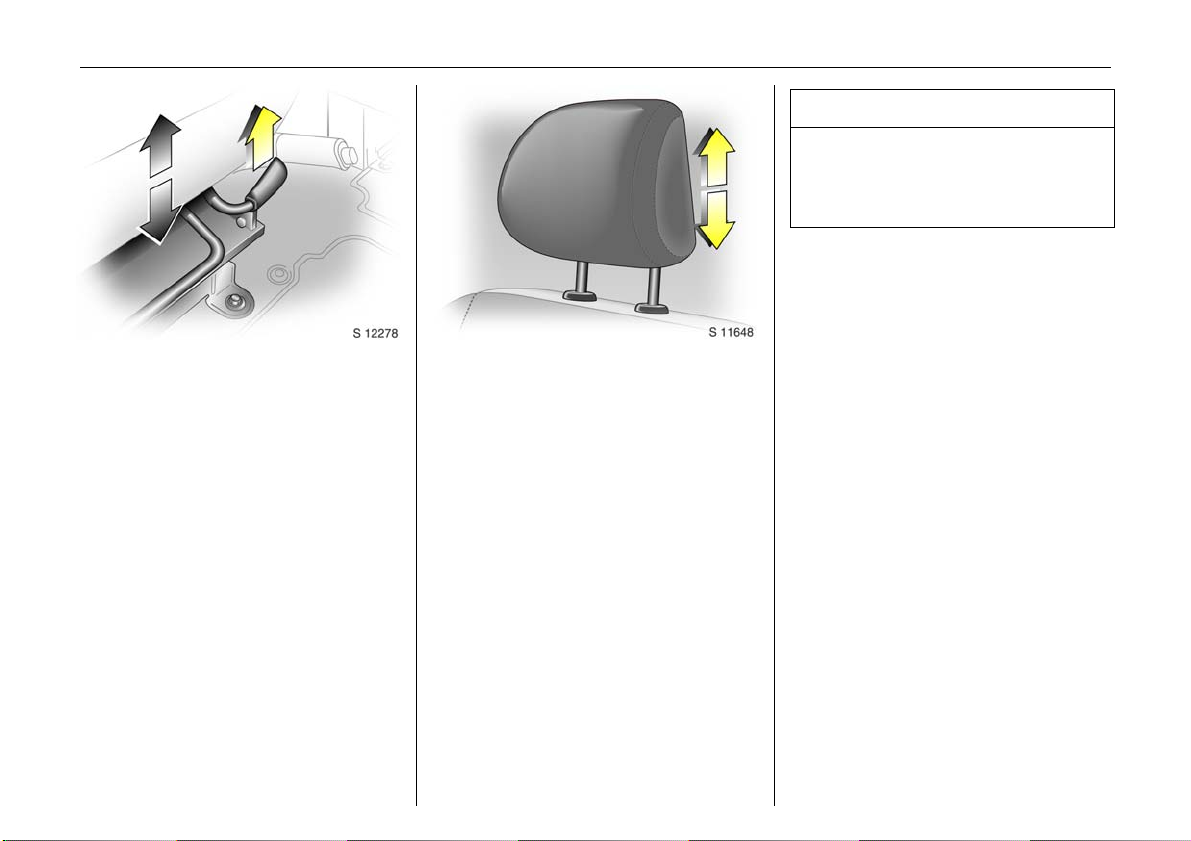
Head restraints
Adjustments - see page 4.
To remove the head restraints, pull lock tab
and pull the restraint upwards.
Rear seats 3
On some variants, the rear passenger
compartment offers storage in the seat
trim s.
To enable long items to be stored under
the seats the centre seat trim cover 3 can
be unclipped.
The load cap acity can be increased furthe r
by folding or removing the rear seats 3.
When folding or removing the rear seat
ensure the arm rests 3 are folded away in
their most upright position. Also remove
the lower seat trim side pockets 3
disconnecting them from the locating clips.
Page 54

Seats, interior 49
Rear seat ac cess 3
To facilitate access to the rear seats, fold
the seat backrest forwards. If necessary
release the two-latch seat belt from its
buckles.
9 Wa rning
Ensure that the backrest returns to its
correct position and the seat belt buc kles
engage securely - see page 58.
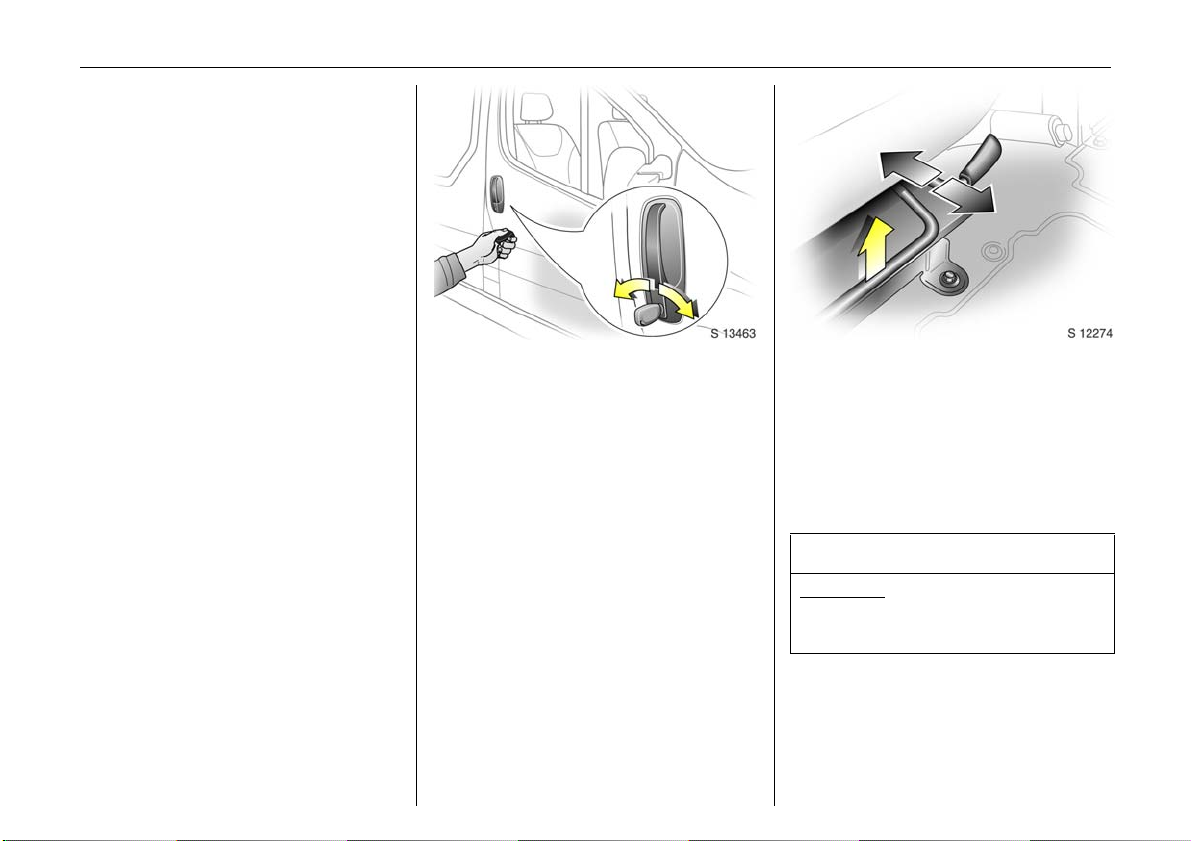
Fold ing sea ts 3
On some variants, the cargo area can be
increased by folding up the rear seats.
Remove the head restraints. Pull the side
ha ndle to re le as e the back re st an d fold
forward onto the seatbase, if necessary
re leasing the two -latch seat be lts fro m the ir
buckles.
Release both locking bars at the rear base
of the seat by pulling rearward s.
Lift and fold the seat assembly, until the
seat frame rests in place.
9 Warning
When folding the seat use caution beware of moving parts. Ensure the seat
is secure whe n completely folded.
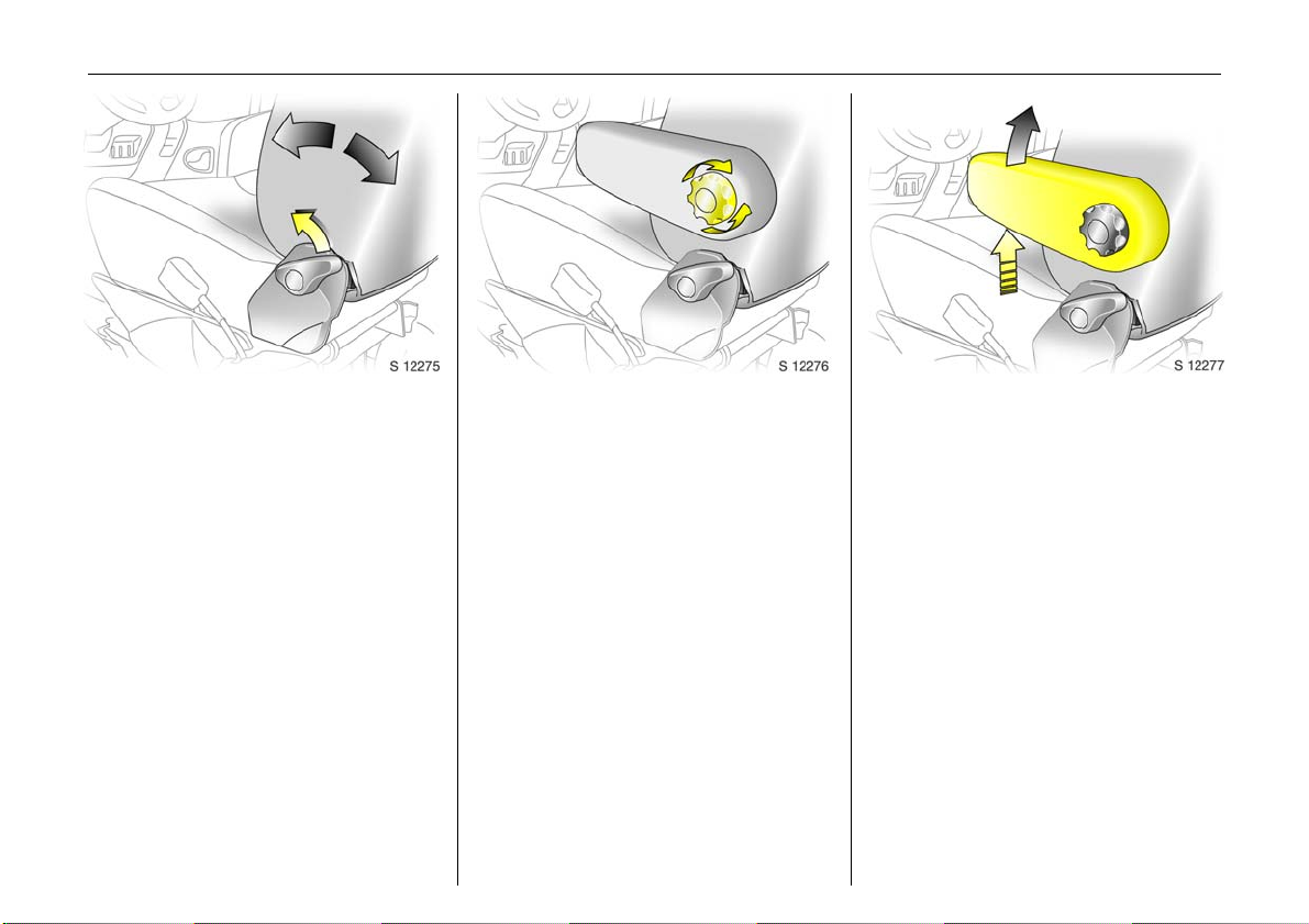
To return the folding seat to the upright
position, support the seat assembly and
release the bar by pulling the bar directly
towards you. Gradually lower the seat
assembly, allow ing the rear support legs to
fold down. Lower the seat completely,
ensuring the rear support le gs are located,
and la tched. R aise the backrest, reinstall
head restraints and connect the seat belts.
9 Warnin g
When installing the seat, ensure that the
seat is properly located on the anchor
points and that the locking catches are
fully engaged, the backrest is returned to
the correct position and the seat belts are
engaged securely.
Page 55

Seats, interior50
Removable rear seats 3
On some variants, the cargo area can be
increased by removing the rear seats.
Release the seats by pressing down and
sliding forwa rd the locking catch located
on the left and right hand seat mountings.
With both catches ra ised, push the seat
unit towards the rear and release them
from the floor anchor points. The seat can
then be lifte d out.
The seats must be removed through the
sliding door only.
9 Warning
Removable seats are heavy ! Do not
attempt to remove without assistance.
When installing the seats, ensure that the
seats are properly locate d on the anchor
points and that the locking catches are
fully engaged.
9 Warnin g
When re-installing seats alw ays ensure
that the row with the folding access
se at B is positioned correctly in front of
the fixed seat row A.
If the seats are incorrectly positioned,
access for passengers is seriously
impeded. Disregard of these instructions
may endanger life.
Page 56

Load c ompa rtment net 3
The load compartment net can b e fitted
behind the front or rear seats to sepa rate
compartments when transporting luggage
or animals.
Installing (front or rear pos ition )
Lift the covers to access the mountings,
insert the load comp artment net rod into
the mounts and secure. Attac h the stra ps
to the lashing eyes behind the front seats;
or to the rings on the rear seat frame, then
tension the straps.
Removing
Tilt strap length adjuster upwards and
unhook strap.
9 Warning
Loose objects in the luggage
compartment should be secured safely.
Seats, interior 51
Load compartment cover 3
To remove:
Lift cover and disconne ct from the side
guides.
Not es on load ing
See page 53.
9 Warnin g
Do not place any heavy or sharp objects
on the cover.
Loose objects in the load com partment
should be secured safely.
Page 57

Seats, interior52
z cargo can then be secured in position
using lashing straps 3 attached to the
anchorage point
The maximum load of each anchorag e
point is 75 kg. To prevent the possibility of
exceeding th is maxim um, the use of
ratchet type lashing straps is to be
avoided.
9 Warnin g
Loose objects in the luggage
co mpartm e nt should be se cured safely.
Lashing eyes 3
Lashing eyes are mounted in the load
compartment to enab le cargo to be
secured in position using lashing straps 3
or a luggage net 3.
The maximum force applied to the lashing
eyes should not exceed 5000 N at 30°.
Load an chorage rails 3
Load anchorage rails 3 m ounted in the
load compartme nt, provide adjustable
anchorage points for securing ca rgo.
z release centre pin of the anchorage
point, by pulling out against spring
tension
z slide the anchorage point to the required
location
z position the anchorage point dire ctly
over the nearest suitable "locking hole"
z release the centre pin of the anchorage
point, ensuring the pin is located
correctly and the anchorage point is
securely locked
Page 58

Notes on loading the vehicle
z Heavy objects in the load compa rtment
should be placed as far forward as
possible. If objects are to be stacked, the
heavier objects should be placed a t the
bottom. Unsecured objects in the load
com partment would be thrown forward
with great force in the event of heavy
braking, for example.
z Secure heavy objects with lashing straps
3 attached to the lashing points. If
heavy loads slip whe n the vehicle is
braked heavily or driven around a bend,
the handling of the vehicle may change.
z The warning triangle 3 and f irst aid k it 3
should a lways be freely accessible.
z No ob jects should be placed on the
instrument panel. They are reflected in
th e glass , o bstruct the driv er’s view and
will be thrown through the vehicle in the
event of heavy braking, for example.
z No objects should be stored in any of the
airbag 3 inflation zones, as injuries may
be caus ed w hen th e a irba g is trig gere d.
z Bulky objects should not be transported
with the back doors open or ajar,
otherwise poisonous exhaust fumes may
enter the vehicle. In addition, the number
plate is only distinguishable and lit
correctly if the doors are closed.
Seats, interior 53
z Weights, payload and roof loa d - see
page 164.
z Driving with a roof load (see also page
95) incre ases th e sen sitivity of th e ve hicle
to cross-winds and has a detrim ental
effect on v ehicle handling ow ing to the
higher centre of gravity of the vehicle.
9 Warnin g
Disregard of these instruc tions may lead
to injuries or e ndanger life . Veh icle
pas se ngers should be inform ed
accordingly.
Page 59

Seats, interior54
Cigarette lighter ) 3
With ignition switched on, press the
cigarette lighter. Heating up ceases once
element is glowing. Withdraw lighter.
Accessory socket
The socket for the cigarette lighter can be
used to connect electrical accessories when
the ignition is switched on.
The maximum power re quirement of
electrical accessories must not exceed 120
watts.
Do not connect any current-delivering
accessories, e.g. electrical charging
devices or batteries.
Connected electrical accessories must
comply with the EC standard in terms of
electromagnetic compatibility
requirements laid down in DIN VDE 40 839,
otherwise vehicle malfunctions may occur.
The use of non-authorised accessories may
cause damage to the socket.
An additional accessory sock et 3 is lo cated
in the rear of the vehicle.
When the eng ine is not running using these
accessory sock ets will cause the ba ttery to
be discharge d.
Page 60

Seats, interior 55
Ashtray 3
Removable to enable universal use for
driver or passengers.
To be used only for ash and not for
combustible rubbish.
9 Wa rning
Disreg ard of these in s tructio ns may lead
to injuries or e nd anger lif e. Veh icle
pass en ge rs should be infor me d
accordingly .
To open: lift up the cover.
To empty: remove the ashtray from the
drink holder recess and empty.
Dr ink h old ers
To use drink holders remove the ashtray
un it.
Over-cab storage area 3
The total weight in this compartment must
not exceed 30 kg.
Page 61

Safety systems56
Safety systems
Three -stage res traint system .... .... ..... 56
Seat belts . ........ ......... ......... ......... ......... 57
Belt tensioners 3 ...... .............. .... .... ..... 59
Airbag systems 3 .... ..... ............. .... ..... 61
Child restraint systems 3 ...... .... .... ..... 68
Exterior mirrors ..... ......... ......... ........ ..... 74
As pherical exterior mirror ..... ........ ..... 74
Sun visors . ........ ......... ......... ......... ......... 74
He ad re straints .... .... ......... ......... ......... 74
Safety accessories 3 .... .... ..... .... ......... 74
Three-stage restraint system
The system comprises
z three-point seat belts
z belt tensioners on the front seats
z airbag sy stems for dri ver a nd f ront
passenger 3.
Th e thre e stag es are a ctivated in sequence
depending on the seriousness of the
accident:
z The automa tic seat belt locking devices
prevent the belt strap from be ing pulle d
out and thus ensure that the vehicle
occupants are re tained in their seats.
z The front seat belt buckles are pulled
downwards. As a result, the seat belts
are instantaneously tightened and the
occupants are made aware of the
deceleration of the vehicle at a very early
stage. This reduces stress placed on the
body.
z The airb ag system is ad ditionally
triggered in the event of a serious
accident involving a frontal impact and
forms a safety cushion for the driver and
front passenger 3. The side airbag
system 3 protects the occupants in the
front of the vehicle in the event of side-on
collisions.
9 Warnin g
The airbag system serves to supplement
the three-point seat belts and belt
tensioners. The seat belts must therefore
always be worn. Disregard of these notes
can lead to injuries which may be fatal.
Vehicle pa ssenge rs sho uld be informe d
accordingly.
Be sure to read the detailed descriptions
of all the restraint systems on the
following pages!
Page 62

Sea t belts
9 Wa rning
Always wear your seat belt - and that
means a lso in urban traffic a nd when you
are a rear seat passenger. It can save
your life!
Pregnant women too must always wear a
se at b e lt .
In the event of an accident, persons not
wearing seat belts endanger their fellow
occupants and themselves.
Seat belts are designed to be used by only
on e pers on a t a time. They are only
suitable for children ag ed up to 12 or
smaller than 150 cm if used in conjunction
with a c hild seat.
Three-point seat belts
The vehicle is equipped with three-point
seat belts with autom atic retractors and
locking devices, allowing freedom of body
moveme nt although the spring tensioned
belts are always a snug fit.
The belt has a “vehicle sensitiv e retractor”
which is designed to lock during heavy
acceleration or de celeration in a ny
direction.
Using th e belts
Fitting the be lt
Pull the belt out evenly from the retractor
and guide it across the body, making
certain that it is not twisted.
Insert the latch plate into the buckle. The
seat backrest must not be tilted back too
fa r; the recommended angle of inclination
is approx. 25°. The lap belt must not be
twisted and m ust fit snugly across the
body. Te nsion the belt frequently whilst
driving by tugging the diagonal part of the
belt.
S afety systems 57
9 Warnin g
On pregnant women in particular the lap
belt must be positioned as low as
possible across the pelvis in order to
prevent pressure on the abdomen.
Bulky cloth ing pre ven ts the belt from fitting
properly. The belt must not rest against
hard or fragile objects in the pockets of
your clothing (e.g. ballpoint pens, keys,
spec ta cles) beca use these could ca use
injury . Do not place any objects (e.g.
handbags) between the belt and your
body.
Page 63

Safety systems58
Upp er anchorage point
height ad justment 3
z Do not adjust height w hilst driving
z Slide adjuster up or down to desired
position
Adj u st he igh t such th at t h e belt p asses
over the wearer’s shoulder and rests
against the shoulder. It must not pass over
the neck or uppe r arm.
Removing the belt
To remove the belt, depress the red pushbutton on the buckle; the belt will retrac t
automatic ally.
Two-latch belt 3
Before fitting the belt, first insert lower
latch plate into the buckle on the outside of
the seat.
The belt can now be used in the sam e way
as a standard seat be lt.
9 Warnin g
The seat b elt will not be effective in the
event of an accident if the lower latch is
not correctly fitted.
When releasing the seat belt, ensure that
the central buckle is always released
before the buckle on the side of the seat.
Alw ays remove the lower latch plate from
the outside buckle before rem oving seats
from the vehicle or to facilitate access to
the rear seats 3 - see page 48.
Page 64

S afety systems 59
Inspection of belts
Periodically inspect all parts of the belt
system for damage and to make sure they
are functioning properly. Have da maged
parts replaced. After an accid ent,
overstretched belts must be replaced by
new ones. We recom mend consulting your
Vauxhall Authorised Repairer.
Do not perform any alterations on the
be lts, the ir anchorages , the au tom atic
retractors or the belt buckles.
Make sure that be lts are not dam aged or
trapped by sharp-edged objects.
Act uation o f be lt tensione rs
The belt tensioners must be replaced after
activation. We recommend that you
consult your Vauxhall Authorised Repairer.
9 Warnin g
The belt tensioners are operational only
when the control indicator is unlit.
The seat belts remain fully operational
even when the belt tensioners have been
actuated.
Belt tensioners 3
The seat belt systems incorporate belt
tensioners. In the event of a head-on or
tail-e nd collision the belt buckles are pulled
downw ards; the diagonal and la p be lts are
instantaneously tightened.
Page 65

Safety systems60
Belt ten sio ner control ind icator
The seat belt tensioners are monitored
electronic ally toge ther with t he air bag, an d
their operational re adiness shown by the
control indicator in the instrument panel.
When the ignition is switche d on, the
control indicator lights up, then
extinguishes. If it does not light up or if it
lights up during driving, there is a fault in
the airb ag system or the belt tensioners
(see also page 64).
9 Wa rning
Have the cau s e of the fault rem edied. We
recommend that you consult your
Vauxhall Authorised Repairer.
The system’s integrated self-diagnostics
allows faults to be quickly remedied. Have
Car Pass on hand when consulting a
Vauxhall Authorised Repairer.
Imp or tant
z Accessories not released for your v ehicle
type and other objects must not be fix ed
or placed within the action zone of the
belt tensioners as they ma y result in
injury if the be lt tensioners are triggered.
z Do not make any modifications to the
components of the belt tensioners, as
this will render the vehicle unroadworthy.
9 Warning
Improper handling (e.g. removal or
installation) can activate the belt
tensioners – risk of injury.
z The belt tensioner and airbag system
control electronics can be found in the
centre console area. In order to avoid
malfunctions, do not store magnetic
objects in this area.
z We recommend that you have the front
seats removed by a Vauxhall Authorised
Repairer.
z The belt tensioners only actuate once.
Please replace belt tensioners that have
been triggered. We recommend that you
consult your Vauxhall Authorised
Repairer.
z When disposing o f th e v ehicle, plea se
observe the applicable safety
regulations. Please have the vehicle
disposed of by a disposal com pany. We
recommend that you consult your
Vauxhall Authorised Repairer.
Page 66

S afety systems 61
When triggered, the driver’s airbag a nd
front passenger airbag 3 inflate in
milliseconds and form safety cushions for
th e driver a nd front pa ssenge r. The
forward movement of the driver and front
passenger is checked and the risk of
injuries to the upper body and head
thereby substantially reduced.
z No impairm ent of view will occur,
because the airbags inflate and deflate
so q uick ly.
9 Warnin g
Airbag systems 3
Front airb ag
Th e front airbag s ystem is identified by the
word “Airbag” on the steering wheel and
above the glove compartment 3.
The front airbag system comprises:
z an airbag with an inflator in the steering
wheel, and a se cond one abov e the
glove compartment 3
z the control elec tronics with impact
se ns or
z the airbag system control indicator v in
the instrument panel.
z Front passenger airbag deactivation 3
The front airbag system is triggered:
z depending on the severity of the
accident
z depending on the type of impact
z within the range shown in the illustration
z independently of the side airbag and
curtain airbag systems 3.
Exa mples:
z Imp act against a non-yielding obstacle:
the front airbag is triggered at low
vehicle spe ed.
z Imp act against a yielding obstacle (such
as another vehicle): the front a irbag is
only triggered at a higher vehicle speed.
The front airbag system provides
optimum protection when the seat,
backrest and head restraint are correctly
adjusted. Adjust the driver's seat
according to the occ upa nt's height such
that with the driver sitting upright, the
steering wheel is held in the are a of its
upper spokes with the driver's arms
slightly bent. The passenger seat should
be as far back as p ossible, with the
backrest upright. Do not place the head,
body, ha nds or feet on the cover of the
airbag system.
Do not place any objects in the area in
which the airbags inflate.
The three-point seat belt must be
correctly fitted (see page 57).
6
Page 67

Safety systems62
The front airbag system will not be
triggered in the event of
z the ignition being switched off
z minor frontal collisions
z accidents in which the vehicle overturns
z collisions involving a side or rear impact
where it would not be of benefit to the
occ upa nt s.
9 Wa rning
Seat belts must therefore always be worn.
The front airbag system serves to
supplement the three-point seat belts. If
you do not wear your seat be lt you risk
being seriously injured, or even thrown
from the vehic le, in the event of an
accident.
The belt helps to keep you in the correct
seating position, in which the front airbag
system will provide you with effective
protection in the event of an accident.
Side airb ag 3
The side airbags are mounted on the
outboar d side s of the fro nt se at bac kre sts
to protect the occupants in the event of a
severe side im pact.
The side airbag system comprises:
z an airbag with infla tor in the back of the
driver's and front passenger's seat
respectively
z the control e lectronics
z side impact sensors
z the airbag systems control indicator v in
the instrument panel.
The side airbag system will be triggere d:
z depending on the severity of the
accident
z depending on the type of im pact
z within the range shown in the illustration
z ind ependently of the front airbag
sy ste m.
Page 68

When triggered the side airbag inflates in
milliseconds and forms a safety cushion for
driver and/or front passenger in the
respective door area. The risk of injury to
the upper body in the event of a side
impact is thereby substantially reduced.
9 Wa rning
The re m ust be no objects in the area in
which the airbag inflates or in the area
between the seat backs and the vehicle
body. Do not place the hands or arms on
the covers of the airbag system s.
Important information - see page 66.
The three-point seat belt must be
correctly fitted - see page 57.
The side airbags will not be triggered in the
event of:
z the ignition being switched off,
z frontal collisions,
z accidents in which the vehicle overturns,
z collisions involving a rear impact,
z collisions involving a side impact outside
the passenger c ell.
Curtain airbag 3
The curtain airbag system is identified by
the badge AIRBAG on the head lining trim.
The curtain airbag system comprises:
z an airbag with inflator in the roof frame
on the d riv er’s an d p ass enge r’s side
respectively,
z the control e lectronics,
z t h e side i mpact se nsors,
z the airbag systems control indicator v in
the instrument panel.
S afety systems 63
The curtain airbag system will be triggered:
z depending on the severity of the
accident,
z depending on the type of im pact,
z within the range shown in the illustration,
z tog ether with the side airbag system,
z ind ependently of the front airbag
sy ste m.
6
Page 69

Safety systems64
When triggered the curtain airbag inflate s
within milliseconds and provides a safety
barrier in the head area on the respective
side of the vehicle. This reduces the risk of
injury to the head considerably in case of a
side impact.
9 Wa rning
The re m ust be no objects in the area in
which the airbag inflate s. Do not place
the hands or arms on the covers of the
airb ag systems. Important information –
see page 66.
The three-point seat be lt m ust always be
correctly fitted – see page 57.
The curtain airbags will not be triggered in
the event of:
z the ignition is switched off,
z frontal collisions,
z accidents in which the vehicle overturns,
z collisions involving a rear impact,
z collisions involving a side impact outside
the passenger c ell.
9 Warnin g
Have the cause of the fault remedied. W e
recommend that you consult your
Vauxhall Authorised Repairer.
The system's integral self-diagnosis facility
allows faults to be quickly reme died. Have
your Car Pass ready to hand when
consulting a Vauxhall Authorised Repairer.
Airbag control ind icator v
The front airbag system, side airbag
sy ste m 3 and curtain airbag system 3 are
monitored electronically together with the
belt tensioners, and their operational
re adiness shown by the control indicator in
the instrument panel. When the ignition is
switched on, the control indicator lights up
then extinguishes. If it does not light up, or
if it lights up during driving, there is a fault
in th e airbag system s or t he be lt tens ione rs.
The systems might not be triggered in the
event of an accident.
Page 70

S afety systems 65
Front passenger airbag deactivation 3
Front and si de ai rba g sy ste ms must b e
deactivated if a child restraint system is to
be mounted on the front passenger seat.
The belt tensioners as well as all airbag
systems for the driver’s seat remain active
when the front passenger seat’s systems
are disengaged.
The switch for deactivating or activating
the airb ag system is located on the front
passenger door.
The chosen setting remains activ e after the
ignition has been switched off. The control
indicator H for front p assenger airbag
deactivation is located in the instrument
panel.
To deactivate
With the front passenger door open, press
switch in and rotate anti-clockwise to
"OFF" position.
The airb ag system s for the front passenger
seat are now dea ctivated.
With the ignition switche d on the control
indicator H will remain illuminated to
indicate deactivation. It is now safe to
place a child seat on the front passenger
seat.
6
Page 71

Safety systems66
To activate:
With the front passenger door open press
switch in and rotate clockwise "ON"
position. Front passenger airbag is now
activated. Upon switching the ig nition on
the control indicator H will illuminate
briefly and then extinguish indicating the
passenger airbag is active.
If H remains illum inated in conjunction with
v indicates a fault within the system.
9 Wa rning
Have the cau s e of the fault rem edied. We
recommend that you consult your
Vauxhall Authorised Repairer.
Imp or tant
z Accessories not released for your v ehicle
type and other objects must not be
affixed or placed in the area in which the
airbags inflate, as they could cause
injury when the airbags are triggered.
z Do not place any objects between the
airbag systems and the v ehicle
occupants; dange r of injury.
z Do not stick or place anything on the
stee ring wheel, instrument p anel, fron t
seat backrests in the vicinity of the
airbags and seat areas or cover them
with other materials.
z The airb ag systems and b elt tensioner
control electronics can be found in the
centre console area. In order to avoid
malfunctions, do not store magnetic
objects in this area.
z Use only a dry cloth or interior cleaner to
clean the steering wheel, instrument
panel, front seat backrests, roof frame
and seat area of the front passenger
seat. Do not use any aggressive cleaning
agents.
z Only protective covers which are
approved for your Vivaro with side
airbag 3 may be fitted on the front
seats. When fitting the protective covers,
make sure that the airb ag units on the
outboard sides of the front seat
backrests are not covered.
z The airbag systems are triggered
independently of each other depending
on the severity of the accident and the
type o f im pact. The s ide airbag system 3
and the curtain airbag system 3 are
trig gered together.
z Each airbag can be triggered only once.
Once triggered, an airbag must be
replaced without delay. We recommend
that you consult your Vauxhall
Authorised Repairer.
z The speeds, directions of movement and
deformation properties of the vehicles,
and the properties of the obstacle
concerned, determine the severity of the
accident and triggering of the airbags.
The degree of dama ge to your vehicle
and the resulting repair costs alone are
not indicative that the criteria for
triggering of the side airbag were met.
Page 72

S afety systems 67
z Do not perform any modifications to the
components of the airbag systems, as
this will render the vehic le unroadw orthy.
9 Wa rning
The systems can be triggered ab ruptly
and cause injury if they are handled
im p r o p er l y.
z We recom mend hav ing the stee ring
wheel, the instrument p anel, all panelling
parts, the door seals, the handles and
the front seats removed by your
Vauxhall Authorised Repairer.
z When disposing o f th e v ehicle, pleas e
observe the applicab le safety
regulations. Please have the vehicle
disposed of by a disposal compa ny. W e
recommend that you consult your
Vauxhall Authorised Repairer.
9 Wa rning
Child restraint systems as well as othe r
heavy objects must never be carried on
the lap of passengers; risk of fa tal injury.
9 Warnin g
While using a child restraint system on
the front passenger seat, the airbag
sy st e m s fo r th e fr o n t p a ss en ge r s ea t mu st
be deactivated; if not, the triggering of
the f ront or side airb ag pose s the risk of
fatal injury to the child.
This is especially the case if ba ckwardsfacing child restraint systems are used on
the front passenger seat.
The system for deactivating the front
passenger seat’s airbag systems is
indicated by a sticker on the side of the
instrument panel, visible when passenger
door is open.
Page 73

Safety systems68
Child restraint systems 3
Vauxhall child restraint systems are
designed specifically for y our vehicle and
thus provide optimum safety for your child
in the event of impact. The use of a
Vauxhall C hild restraint system is therefore
recommended.
9 Wa rning
While using a c hild restraint system on
the front passenger seat, the airbag
systems for the front passenger seat must
be deactivated; if not, the triggering of
the front or side airbag poses the risk of
fatal injury to the child.
This is especially the case if back wardsfacing child restraint systems are used on
the front passenger seat.
Selec ting the rig ht system
Your child should be transported facing
re arwards in the vehicle as long as
possible. It is appropriate to change the
system when the child’s head can no longer
be p rope rly s u pported at ey e he ight. Th e
child’s cerv ical vertebrae are still very weak
and in an accident they suffer less stress in
the semi-prone rearward position than
when sitting upright.
Not e
z Children under 12 years or und er 150 cm
tall should only travel in an ap propria te
child safety seat.
z When transporting children, use the child
restraint systems suitable for the child's
weight.
z Ensure that the child restraint system to
be installed is compatible with the
vehicle type.
z The covers of the Vauxhall child restraint
sy ste m can b e wiped cle an.
z Do not stick anything on the child
restraint systems and do not cover them
with any other materials.
z A child restraint system which has be en
subjected to stress in an accident must
be replaced.
z Ensure that the mounting loc ation of the
child re straint system within the vehicle is
correct.
z You should also ob se rve th e i ns truction s
on installation and use supplied with the
child restraint system.
Page 74

The following Vauxhall child restraint
systems have been approved for
installation in your Vivaro:
Group, weight and age
1)
class
0
From birth - 10 kg,
Vauxhall
system
Baby Safe
0 - 10 months
0+
From birth - 13 kg,
0 - 2 years
I From 9 - 18 kg,
Duo Isofix
8 months - 4 years
II
from 15 - 25 kg,
Kid
3 years - 7 years
from 22 - 36 kg,
III
6 years - 12 years
1)
We reco mmend the use of each system
until the child reaches the up per weigh t
li mi t .
If child restraint systems of other
manufacture are to be installed, ensure
that they conform to the appropriate
safety regulations.
9 Wa rning
Disregard of these instructions may lead
to injuries or endanger life.
S afety systems 69
The country in w hich you are travelling
may prohibit child seat installation in
certain locations. Alway s obse rve local or
national regulations.
6
Page 75

70 Safety systems
Front seats - all variants
Group, weight and age class
Fa cin g
directi on
Single seat - front passenger
without
airbag
with airbag
- no side
airbag
0:
up t o 10 kg or approx. 10 months
0+:
up t o 13 kg or approx. 2 yea rs
Rearward U U
I: 9 to 18 kg or approx. 8 months - 4 yea rs Forward U U
II :
15 to 25 kg or approx. 3 - 7 years
II I:
22 to 36 kg or approx. 6 - 12 years
1)
If ad justa ble, ensur e s eat is i n it s rea rmost p osition . M ak e s ure vehi cle seat be lt i s a s straig ht a s po ssible b et ween shou lde r and upper achorage point.
2)
Ensure the front passenger airbag system is deactivated when installing a child seat in this position. See page 65.
U = Suitable for u niversal catego ry restraint syst ems f or use in this m ass group , in con jun ct ion with th ree-point sea t b elt.
UF = Suitable for u niversal catego ry forward facing restraint systems for use in th is mas s group, in conjunction with three-point s ea t be l t.
Forwar d U U
2)
2
2
X = Seat position not s uita ble for children of this mass group.
1)
with side
airbag
2
U
2
U
2
U
Benc h seat - front passenger
w ithout airbag with airbag
centre outer centre outer
X
U
X U
UF U UF U
UF U UF U
9 Wa rning
While using a child restraint system on the front passenger seat, the airbag systems for the front passenger seat must be deactivated; if
not, the triggering of the front or side airbag poses the risk of fata l injury to the child.
This is especially the case if back wards-facing child restraint systems are used on the front passenger seat.
2
2
2
Page 76

Combi - rear seats
S afety systems 7 1
Group, weight and age class
Facing
direct ion
0:
up to 10 kg or approx. 10 months
0+:
up to 13 kg or a pprox. 2 y ears
Rearward
I: 9 t o 18 kg or approx. 8 months - 4 years Forwa rd
II :
15 to 25 kg or approx. 3 - 7 years
II I:
22 to 36 kg or approx. 6 - 12 y ears
U = Suitable for u niversal catego ry restraint syst ems f or use in this m ass group , in con jun ct ion with th ree-point sea t b elt.
L = Suitable only for specifically approved child restraints. Vauxhall has approved child restraint systems from th e ’Baby-s afe’, ’Duo-Isofix’ and ’Kid’
rang es. W e recommend that yo u consult a Vauxh all Authorised Rep airer.
+ = S eat with Isof ix m ount ing a v ailable. W hen m ount i ng Iso fix, only Isof ix child rest raint sy stem s th at have b een approved f or the vehicle may be u sed.
We recom mend th at you consult a Va uxhall Authorised Repairer.
X = Seat position not s uita ble for children of this mass group.
Forward U
2nd row bench seat 3rd row bench seat
Outer Centre Outer Centre
U
UU,+
U,+ XX
X
U
X
L+
X
Page 77

72 Safety systems
Tour - rear s eats
Group, weight and age class
Faci ng
direction
0:
up to 1 0 kg or approx. 10 months
0+:
up to 1 3 kg or approx. 2 years
Rearward
I: 9 t o 18 kg or approx. 8 months - 4 years Forward
II :
15 to 25 kg or approx. 3 - 7 years
II I:
22 to 36 kg or approx. 6 - 12 years
1)
On left-hand drive 7 seater models (2 seat ben ch in 2nd row) it is p ermissible to in stall a universal child seat on the third seat row but only on the right
hand outboard side due to increased clearance in front of it.
U = Suitable for u niversal catego ry restraint syst ems f or use in this m ass group , in con jun ct ion with th ree-point sea t b elt.
L = Suitable only for specifically approved child restraints. Vauxhall has approved child restraint systems from th e ’Baby-s afe’, ’Duo-Isofix’ and ’Kid’
rang es. W e recommend that yo u consult a Vauxh all Authorised Rep airer.
+ = S eat with Isof ix m ount ing a v ailable. W hen m ount i ng Iso fix, only Isof ix child rest raint sy stem s th at have b een approved f or the vehicle may be u sed.
We recom mend th at you consult a Va uxhall Authorised Repairer.
Forwar d U U X
2nd row benc h seat 3rd row bench se at
Outer Centre Outer Centre
U
U
U,+ X
U,+ X
1)
1
1
X
L+
X
X = Seat position not s uita ble for children of this mass group.
Page 78

Crew Cab - rear seats
S afety systems 7 3
Group, weight and age class
0:
up t o 10 kg or approx. 10 months
0+:
up t o 13 kg or approx. 2 yea rs
I: 9 to 18 kg or approx. 8 months - 4 years Forward
II :
15 to 25 kg or approx. 3 - 7 years
II I:
22 to 36 kg or approx. 6 - 12 years
X = Seat position not s uita ble for children of this mass group.
Facing
direction
Rearward
Forward X
Rea r bench sea t
Outer Centre
XX
XX
X
Page 79

Safety systems74
Exterior mirrors
For the safety of pedestrians, the exterior
mirrors will swing out of their normal
mounting position in the event of an
accident-lik e im pact.
Aspherical exterior mirror
In crea ses the field of v isio n . S lig ht
distortion means that it is somewhat
difficult to estimate the distance b etween
th e v ehicle and tho se behind it.
Sun visors
The sun visors are padded and ca n be
swung up a nd down and to the side for
protection of driver and passenger against
glare.
Head restrai nts
Do not a ttach objects or components that
are not approved for the Viva ro, to the
head restraints. These affect the protective
effect of the head restra ints and ca n be
propelled through the vehicle in an
uncontrolled m anner if the driver brakes
hard or an accident occurs.
Safety accessories 3
The wide range of Vauxhall acce ssories
allows you to equip your vehicle in
accordance with your own wishes. In
addition to safety accessories, items for
improving comfort a nd a complete range
of vehicle care products you will find many
articles which will be of great value to you
wh e n need ed.
All items are “Genuine Va uxhall Parts and
Accessories”, guaranteeing high quality
and an accurate fit.
Your Vauxhall Authorised Repairer will be
happy to advise you, for example with
regard to:
z Vauxhall child restraint system
z Tow rope
z Tow rod
z Jump leads
z Spare bulb kit
z Spare fuse kit
z Halogen fog lights
z Mud flaps
z Magnetic lig ht
z Warning triangle
z First-aid kit (box)
z First-aid kit (cushion)
Page 80

Lightin g 75
Lighting
Exterior lights ................ .... ......... ......... 75
Autom atic dipped beam
activation 3 .. ......... ..... ......... ........ .....
Headlight range adjustment ? ......... 76
Fog tail light r .... .... ..... .... ............. ..... 77
Front fog lights > 3..... .... ..... .... ......... 77
Re verse lig hts .. ..... .... .............. .... .... ..... 77
Door-to-door lighting function 3 . ..... 77
Interior light.............. ..... ......... ........ ..... 77
Instruments, cigarette lighter ....... ..... 78
He adlights when driving abroad . ..... 78
76
Vehicles with daytime running lights 3:
When the ig nition is on, the dipped beam is
on and the instrument illumination is
subdued.
Th e day time ru nning lights go off when the
ignition is switched off.
Follow the regulations of the country in
which you are driving w hen using daytime
running lights and front fog lights 3.
Driving ab road - see page 78.
Exterior lights
Turn light switch:
7 =Off
0 = Parking lights
9 P = Dippe d or main beam
Dipped/main beam a nd headlight flash,
see page 12.
In posit ions 0 and 9, the tail lights and
numb er plate light are also illuminated.
Page 81

Ligh ting76
Autom atic dipped b eam
activation 3
Dipped beam switches on or off
automatically when the engine is running
based on the outside light conditions.
The exterior lights switch off w hen the
ignition is switched off.
To activate:
1. Switch on the ignition.
2. Turn light switch to 0 a nd return 7.
3. Repeat stage 2 within approximately 5
se cond s.
This action is confirmed with a double
audible warning.
To deactivate:
1.Switch on the ignition.
2. Turn light switch to 0 and return 7.
3. Repeat stage 2 within approximately 5
seconds.
This action is confirme d with a single
audible warning.
For reasons of safety it is advisable to have
the automatic dipped beam function
activated .
Turn signals, hazard warning
flas he rs
See page 13.
Headlight range adjustment ?
With dipped beam switched on, adjust
headlight range to suit vehicle load.
Correct adjustment of the headlight range
reduces dazzle for other road users.
z No load = 0
z Loaded up to permissible
maximum weight = 4
Page 82

Lightin g 77
Fog tail light r
Front fog lights > 3
Rotate switch, control indicators > and r
in instrument panel:
7 = Off
> = Front fog lights on
> and r = Fog tail light and
front fog lights on
Reverse lights
Come on whe n reverse gear is engaged
and ignition is switched on.
Door-to-door lighting
function 3
The headlights are switched on and remain
illuminated for a short time after the
vehicle is parked.
To activate:
1. Switch off ignition.
2. R e m ove ignition key.
3. Open driv er’s do or.
4. Pull lever towards steering wheel.
The dipped be am illuminates for approx.
30 seconds. This action can be re peated up
to four times to a max imum pe riod of two
minutes.
Switching on the ignition or rotating the
lig ht switch cancels the function before the
lig hts automatically switch off.
Interior lig ht
Operated by tilting the light lens. With the
light in its central position, the light
functions as a courtesy lig ht and
illuminates when the front doors are
opened.
Once the front doors are close d, the
courtesy light goes out after a 15 second
delay.
The interior light extinguishes immediately
if the ignition is switched on.
Page 83

Ligh ting78
Load compartment lights
Van
Operated by tilting the light lens.
Comb i / Tour / C rew Ca b
Operated by tilting the light lens to one of
3-positions:
z On constantly
z C ontrolled b y the function of the interior
light
z Off constantly
Instruments, cigarette lighter
Com es on when exte rior lights are switched
on.
Headlights when driving abroad
The asymmetrical dipped beam increases
the field of vision on the near side of the
lane.
When driving in c ountries which drive on
the op posite side of the road, this causes
glare for oncoming traffic.
To av oid glare, conventional headlight
glasses must be prov ided with a black
cover strip. Consult a workshop. We
recommend your Vauxhall Authorised
Repairer.
Page 84

Windo ws 79
Windows
Door windows ...... ......... ......... ........ ..... 79
Electrically operated door w indows 3 80
Sliding side windows 3 ..... ............. ..... 80
9 Warning
Care m ust be take n wh en operating the
electrically operated windows. There is a
risk of injury, particularly for children, and
a danger that articles could become
trapped.
Vehicle pas se ng ers should be inform ed
accordingly.
Make sure that all vehicle occupants
know how to operate the windows
correctly.
Keep a close watch on the windows when
closing the m. Ensure that nothing
becomes trapped in them.
Before leaving the vehicle, remove the
ignition key in order to prevent
unauthorized operation.
Door windows
Th e d o or w i nd ow s c an be op erat ed w i t h
the crank.
Page 85

Windo ws80
Electrically operated door
windows 3
Th e driver’s window is operated b y the
switch located in the driver’s door.
To open the window, push the top of the
switch and to close, pull the top of the
switch. The window stops when switch is
released.
With the e ngine running: briefly pushing or
pulling the switch fully opens or closes the
driver’s side window. Briefly press the
switch again to stop the window during this
opera tion.
The passenger’s window is operated by a
switch in each front door.
To open the window , push the top of the
switch and to close, pull the top of the
switch. The window stops when the switch
is released.
9 Warning
Before leaving the vehicle, remove the
ignition key in order to prevent
unauthorized operation of the windows
(risk of injury).
Sliding side windows 3
To open, pull up catch a nd slide open.
To close, pull up catch and slide window
until catch engages.
Note: during window opening or closing,
keep the catch raised to allow the glass
sufficient clearance.
Page 86

Heating, ventilation 81
Heating, ventilation
He ating an d ven tila tion system ... ..... 81
Rear air vents 3 ....... ..... .... ..... ............. 83
He ating the foot area .. .... ......... ......... 84
Window dem isting an d defrosting .... 84
Re -circulation button.... .... ......... ......... 85
Air conditioning system 3 ..... .... .... ..... 85
Rear air conditioning system 3 .... ..... 86
Heated rear windows 3, heated
exterior mirrors 3 .. .............. .... .... ..... 87
Heated front seats 3.... .... ..... .... ......... 88
Heating and ventilation system
Vauxhall air mixture system: by mixing cold
and hot air the temperature can be
regulated without delay and held
practically constant at all speeds.
Heating and v en tilati on controls
Air distribut ion switch
M To hea d area
L To head and foot area
K To foot area
J To defrosters and foot area
V To defrosters
The rotary switch can be set to any
intermediate position in ord er to a djust the
air distribution to suit personal
requirements.
Open the ventilation jets when the switch is
set to M or L.
Page 87

Heating, ventilatio n82
Temperature switch
To red Hotter
To blue Colder
Fan s w itch
Four s pee ds:
0 Off
4 High speed
The rate of air flow is determined by the
fan. The fan should therefore also be
switched on during driving.
Centre ventilation jets
Pleasant ventilation to the head area is
controlled by the position of the
temperature switch.
To open jets, turn regulating wheel:
Turn to left = Open
Turn to right = Closed
The air supply is increased by switching on
the fa n.
The air flow can be directed as desired by
tilting and swivelling the fins.
Page 88

Heating, ventilation 83
Side ventilatio n jets
Dep ending upon the position of the
temperature switch, air will be directed into
th e v ehicle via these jets .
Th e jets are ope ned a nd closed by means
of the regulating wheel.
The a ir flow can be directed as desired by
tilting and swivelling fins.
To increase the air supply, switch on the
fan.
Door window defroster vents
Air distribution switch set to V or J: c old
or heated air w ill be directed onto the
windscreen and onto the door windows
(mainly in the area of the exterior mirrors).
Rear air vents 3
Operational when air distribution switch is
set to L, K or J.
Unheated or h ea te d air will b e directed in to
the rear passeng er comp artment.
The air flow is biased towards the central
and right hand vents for optimum
distribution.
Ventilation
z Turn temperature switch to blue.
z Switch on fan.
z For maximum ventilation in head area:
set air distribution switch to M and open
all jets.
z For ventilation to foot area: set air
distribution switch to K.
z For simultaneous ventilation to head
and foot areas: set air distrib ution switch
to L.
Page 89

Heating, ventilatio n84
Heating
The amount of heat is dependant on the
engine temperature and is thus not fully
attained until the engine is warm.
For ra pid warming of the passenger
compartment,
z Turn te mperature switch to re d.
z Switch on fan.
z Set the air distribution switch to the
desired position.
The com fort and general well-being of the
vehic le occupants are to a large extent
depende nt on a correct setting of the
ventilation and heating.
Heating the foot area
z Turn temperature switch to red.
z Set the air distribution switch to K.
z Sw itch on fan.
Window demisting and defrosting
z Turn temperature switch to red.
z Switch on fan.
z Set air distribution switch to V.
z Open sid e ventilation jets as required
and direct them towards the door
windows.
z Close centre ventilation jets.
z Switch on heated re ar windows 3 .
For simulta neous warming of the foot area,
set a ir distribution switch to J.
Page 90

Re-circulation button
During ’normal’ operation, the heating and
ventilation and air cond itioning systems
use outside air, however, to prevent fumes
from entering the vehicle when in
stationary traffic press the 4 b utton,
contol indicator illuminate s and air will be
recirculated.
Re circulate d air s hould only be used fo r
brief periods due to the gradual
deterioration in the air quality and increase
in humidity.
Air conditioning system 3
The air conditioning system is designed to
operate in conjunction with the heating
and ventilation system to prov ide
maximum comfort under any w eather
conditions.
The air conditioning system cools the air
and removes moisture from it. It is
operational on ly in tem peratures abov e
approx. +4 °C, with the engine running and
with the fan switched on:
Press AC button - control
indicator illuminates
Press AC button again = off
=on
Heating, ventilation 85
Once activated the air conditioning system
is operated via the normal he ating and
ventilation controls.
To improve efficiency of the air
conditioning, always close the windows to
prevent chilled air from escaping.
Switc hing on the air conditioning will assist
in windscreen demisting.
In very hot temperatures, before switching
on the air conditioning, allow hot a ir to
escape from the vehicle by opening the
windows.
Wh en the syste m is sw itc he d on, at least
one ventilation jet m ust b e open so that the
evaporator does not ice up due to lack of
air movement.
When the air conditioning is on, fuel
consumption incre ases. Switch off the
system when ev er it is not requ ired .
Maintena nce
To ensure efficient performance of the air
conditio ning syste m, it mu st be switch ed o n
once a month for a short time, irrespective
of the weathe r and time of year (possible
only when outside temp erature is above
+4 °C ).
Malfunctions in the system must not be
rectified by the owner; consult a workshop.
We recommend your Vauxhall Authorised
Repairer.
Page 91

Heating, ventilatio n86
Glove com partment cooler 3
Slide the control upwards to allow the air
conditioning system to also keep the
contents of the glove compartment cool.
Rear air conditioning system 3
The rear air conditioning 3 sy ste m co ols
the air and removes moisture from it. It is
operational on ly in tem peratures abov e
approx. +4 °C, with the engine running.
It is actuated in conjunction with the
driver’s compartment air conditioning:
Press AC button = on
Press AC button
again
=off
Rear p assenger compartment
fan sw itch 3
The fan assists air flow to the passenger
compa rtment. Switching on the fan whilst
the air conditioning is actuated, will allow
conditioned a ir to be distributed.
The ra te of air flow is determined by the
fan.
3 speeds:
0 Off
3 High speed
Wh en the syste m is sw itc he d on, at least
one ventila tion jet, located in the roof must
be ope n so that th e evapo ra tor does n ot
ice up due to lack of air movement.
Page 92

Heating, ventilation 87
Rear passenger compartment
heating 3
The fan assists air flow to the rear
passenger compartment via the rear air
vents.
The rate of air flow is determined by the
fa n.
3 spe eds:
0 Off
3 High speed
Heated rear windows 3,
heated exterior mirrors 3
Operates only with engine running.
Pushbutton Ü on instrument panel.
Press = on
Press again = off
Control indicator on pushbutton
illuminates when in use.
Tu rn off as soon as rea r vision is clear. The
heating switches off automatically after
approx. 10 minutes.
Page 93

88 Heating, ventilation
Heated front seats 3
Pushbutton ß in trim panels of the seat.
Operate only with e ngine running.
Press = on
Press again = off
Seat heating is thermostatically controlled
and will automatica lly cease when the se at
temperature is sufficient. The control
indicator will illuminate whe n system is on,
not just whe n he ating.
Page 94

Tecshift 89
Tecshift
Transmission display ........ ............. ..... 89
Starting the engine.. ..... .... ..... .... ......... 89
Tecs hift operation ... ..... .... ......... ......... 90
Winter programme V... ............. .... ..... 91
Laden p rogram me kg .. .... ..... ............. 92
Kick down . .... .... ..... ............. ..... .... .... ..... 92
Engine braking as s istance ................. 92
Stopping the vehicle ..... ......... ........ ..... 93
Parking ..................... ..... .... ..... ............. 93
Rockin g the vehicle .. ..... ......... ........ ..... 93
Manoeuvring the ve hicle .. ......... ......... 93
Fault W.... .... ............. ..... .... ..... ............. 94
Interruption of power s upply ........ ..... 94
The semi-automatic Tecshift transmission
permits manual (manual m ode) or
automatic gearshifting (automatic mode),
both with fully autom atic clutch control.
9 Warning
Disregard of these instructions m ay le ad
to injuries or endanger life.
Tran smission display
Shows the mode, programme and current
gear.
Starting the engine
Depress foot brake, turn on ignition.
If T is shown in the transmission display
th e foot bra ke is n ot depressed. When "N"
is shown in the transmission display the
engine can be started.
It is not necessary to select the neutral "N"
position before starting. If a gear other
th an " N " is s ele c ted , de p res s th e fo o t b ra k e
and there will b e a short delay whilst the
transmission automatically shifts into
neutral.
Page 95

Tecshift90
Tecshift operation
The selector lever need s to be moved in the
appropriate direction only slightly. It then
returns to the centre position. Observe the
gear / mode ind icator in the transmission
display.
Sele cting neutra l
Move the selector lever toward N.
Automat ic mode
When the engine is started, Tecshift is in
autom atic mode "A" is show n in the
tra nsmission display.
To engag e 1st ge ar d epress fo ot brak e and
move se lector lever towa rds +.
The vehic le will begin to "creep" when the
foot brake is released without accelerating.
It is p ossible to s tart o ff quickly by releas ing
the foot brake and accelerating.
In automatic mode the transmission shifts
to othe r gears automatically dependent on
driving conditions.
Manua l mode
Manual gearshifting is possible in manual
mode. If the vehicle is in automatic mode,
manual mode can be selected by moving
the selector lever toward A/M. The curre nt
gear will appear in the transmission
display.
To engage 1st gear depress foot brake and
move selector lever towards + or - and 1 will
appear in the transmission display.
Moving selector lever toward:
+ Shifts to a higher gear.
- Shifts to a lower gear.
If the engine speed is too low Tecshift will
automatically shift to a lower gear even in
Manual mode. This prevents the engine
from stalling.
If a higher gear is selected when the
running speed is too low, or a lower gear
when the speed is too high, no shift is
effected. This prevents the engine from
running at too low or too high revs.
Gears can be skipped by moving the
selector lever repeatedly at short intervals.
Page 96

Tecshift 91
In order to protect Tecshift at extremely
high clutch temperatures, an intermittent
audible warning may sound. In such cases
depress the foot brake, select "N" and
app ly th e han dbrak e allo wing the clutch to
cool down.
If the vehicle is switched to manual mode
while winter programme is active, the
Win ter pro gramm e is switched off .
Sele cting reverse
Enga ge only when the vehicle is sta tionary.
With the foot brake depressed, move the
selector lever toward R. Rev erse gear is
engaged and "R" appe ars in the
tr ansm iss ion disp lay .
Th e veh icle begins to cre ep w he n th e foo t
brake is released. Accelera te gently to
move.
Winter programme V
In the event of difficulties starting-off on
slippery surfaces, press button V and V is
shown in the transmission display. Tecshift
switches to automatic mode and the
vehicle sets off in a suitable gear.
The Winter programme is switched off by:
z pressing button V again,
z turning off the ignition.
Page 97

Tecshift92
Engine braking assistance
Autom atic mode
When driving downhill Tecshift doe s not
shift into the higher gears until a fairly high
engine speed has be en reached. During
braking Tecshift shifts down to a lower
gear in good time.
Manua l mode
To u tilize th e engine braking effect, select a
lower gear in good time when driving
downhill.
Laden programme kg
It is possible to use Laden programme in
both manual and automatic modes. In
both cases, the gear shifting patterns are
adapted automatically for carrying an
in cr eased pa yload. Press button kg, Lad en
programme will b e selected and kg will
appear in the transm ission disp lay. Tecshift
will then select optimized gear shift
patterns.
The Lade n programme is switc hed off by:
z pressing button kg again,
z turning off the ignition.
Kick dow n
Accelerator pedal pressed past the
pressure point: below certain speeds, the
tra nsmission shifts down into a lower gear.
Full engine power is available for
acceleration.
When the engine speed approaches its
upper limit, the transmission shifts to a
higher gear during kickdown even in
manual mode.
Without kickdown this automatic shift is
not affected in manual mode.
Page 98

Tecshift 93
Stopping the vehicle
In automatic or manual mode, once the
vehic le is stationary first gear engages
automatically and the clutch opens. In R,
reverse remains engaged.
When stopping on gradients engag e
handbrake or depress brake pedal. To
prevent overheating of the clutch, an
intermittent, audible warning may sound
as a signal to depress the foot brake or
apply the handbrak e.
Switch off engine if stopping for a lengthy
period, e.g. in traffic jams.
Parking
Before leaving the vehicle:
z engage handbrake,
z remove ignition key.
The most recently engaged gear (indicator
in transmission display) remains engaged.
With N , no gear is engaged.
When the ignition is switched off Tecshift
no longer responds to movements of the
selector lever.
If the ignition is not switched off, or the
ha ndb ra ke has no t be en a p pli ed, an
inte rmittent audible warning may sound
upon opening the driver’s door.
Rocking the vehicle
If it becomes necessary to rock the vehicle
to free it from sand, mud, snow or a hole,
move the selector lever between R and A
(o r + or -) in a rep eat pattern w hile app ly ing
lig ht pressure to the accelerator pedal. Do
not rac e the engine and avoid sudden
acceleration.
This applies only in exceptional
circumstances mentioned above.
Man oeu vr in g the ve hi cle
To manoeuvre the vehicle back and forth
during attempts to park or in ga rage
entrances, the creeping movement can be
utilized by releasing the foot brake.
Never actuate the accelerator and brake
pedals simultaneously.
In order to protect Tecshift at extremely
high clutch temperatures, an intermittent
audible warning may sound. In such cases
depress the foot brake, select "N" and
app ly th e han dbrak e allo wing the clutch to
cool down.
Page 99

Tecshift94
Fault W
If a fault occurs in Tecshift, control
indicator W will be shown in the
tr ansm iss ion disp lay .
You can continue driving, provided you
drive with care and anticipation. Consult a
workshop to have the cause of the fault
eliminated. We recommend your Vauxhall
Authorised Repairer. The system's integral
self-diagnosis facility allows faults to be
quickly remedied.
Interruption of power supply
The clutch is not disengaged if the vehicle
battery is discharg ed and a gear has been
selected. The vehicle cannot move.
If the battery is flat, start the vehicle using
jump leads - see page 126.
If the cause of the interruption to the power
supply is not a discharged battery, consult
a w orks ho p. We re comme nd yo ur V aux ha ll
Authorised Repairer.
Page 100

Dr iv in g hint s 95
Driving hints
The first 600 miles (1000 km)
Driv e your v ehicle at various spe eds. Do
not use full throttle. Never allow the engine
to labour at low revs.
Make good use of all gears. Depress the
accelerator pedal a ma ximum of around
three quarters of the available p edal travel
in all gea rs and drive ranges.
Do not drive faster than three quarters of
maximum speed.
The information concerns the engine and
parts of the power train, e.g. the final drive.
Never coast with engine not
run ning
Many units will then not function (e .g. turn
signal indicators, brake servo unit, power
steering, airbag system). Driving in this
manner is a d anger to yourself a nd others.
Brake servo unit
With the engine not running the brake
servo unit is no longer effective once the
brake pedal has bee n depresse d once or
twice. The braking effect is not red uced but
substantia lly greater foot pressure is
necessary to stop the vehicle.
Power steering
Never leave the steering wheel on full lock
when the vehicle is stationary as this m ay
damage the power steering pum p.
If the po wer steering sho uld fail - e. g. when
the vehicle is being towed with the engine
switched off - the vehicle can still be
properly steered b ut considerab ly greater
effort is necessary.
Driving in mountainous terrain or
with caravan/trailer
Electrically driven fan: The fan cooling
capacity is not dependant on engine
speed. It is not necessary, therefore, when
driving uphill to shift down into a lower
gear if the vehicle can climb in a higher
gear.
Driving with a roof load
Do not exceed the permissible roof load.
For safety reasons, distribute the load
evenly and secure it tightly with straps so
that it cannot slip. Set the tyre inflation
pressure to the value given for full load. Do
not drive faster than 75 mph (120 km/h).
Check a nd retighten straps at frequent
intervals.
 Loading...