

Nissan Murano 2003 User Manual

ENGINE MECHANICAL
B ENGINE
A
EM
SECTION EM
CONTENTS
PRECAUTIONS .......................................................... 3
Precautions for Drain Engine Coolant ...................... 3
Precautions for Disconnecting Fuel Piping .............. 3
Precautions for Removal and Disassembly ............. 3
Precautions for Inspection, Repair and Replace-
ment ......................................................................... 3
Precautions for Assembly and Installation ............... 3
Parts Requiring Angular Tightening ......................... 3
Precautions for Liquid Gasket .................................. 4
REMOVAL OF LIQUID GASKET SEALING .......... 4
LIQUID GASKET APPLICATION PROCEDURE ..... 4
PREPARATION ..................................... ...................... 5
Special Service Tools ............................................... 5
Commercial Service Tools ........................................ 7
NOISE, VIBRATION AND HARSHNESS (NVH)
TROUBLESHOOTING ................... ............................. 9
NVH Troubleshooting —Engine Noise ..................... 9
Use the Chart Below to Help You Find the Cause
of the Symptom. ....................................... ....... ....... 10
DRIVE BELTS ............................................................11
Checking Drive Belts ...............................................11
Tension Adjustment .................................................11
AL TERNATOR AND AIR CONDITIONER COM-
PRESSOR BELT ................................................. 12
POWER STEERING OIL PUMP BELT ............... 12
Removal and Installation ........................................ 12
REMOVAL ........................................................... 12
INSTALLATION ................................................... 13
AIR CLEANER AND AIR DUCT ............................... 14
Removal and Installation ........................................ 14
REMOVAL ........................................................... 14
INSTALLATION ................................................... 15
CHANGING AIR CLEANER FILTER ................... 15
INTAKE MANIFOLD COLLECTOR .......................... 16
Removal and Installation ........................................ 16
REMOVAL ........................................................... 17
INSPECTION AFTER REMOVAL ....................... 18
INSTALLATION ................................................... 18
ENGINE MECHANICAL
INTAKE MANIFOLD .................................................20
Removal and Installation ........................................ 20
REMOVAL ...........................................................20
INSPECTION AFTER REMOVAL ....................... 20
INSTALLATION ................................................... 21
EXHAUST MANIFOLD AND THREE WAY CATA-
LYST ........... .......................... ................................. .... 22
Removal and Installation ........................................ 22
REMOVAL ...........................................................22
INSPECTION AFTER REMOVAL ....................... 24
INSTALLATION ................................................... 24
OIL PAN AND OIL STRAINER ................................. 26
Removal and Installation ........................................ 26
REMOVAL ...........................................................26
INSPECTION AFTER REMOVAL ....................... 31
INSTALLATION ................................................... 31
INSPECTION AFTER INSTALLATION ................34
IGNITION COIL .............................................. ....... .... 35
Removal and Installation ........................................ 35
REMOVAL ...........................................................35
INSTALLATION ................................................... 35
SPARK PLUG (PLATINUM-TIPPED TYPE) .............36
Removal and Installation ........................................ 36
REMOVAL ...........................................................36
INSPECTION AFTER REMOVAL ....................... 36
INSTALLATION ................................................... 37
FUEL INJECTOR AND FUEL TUBE ........................ 38
Removal and Installation ........................................ 38
REMOVAL ...........................................................38
INSTALLATION ................................................... 40
INSPECTION AFTER INSTALLATION ................42
ROCKER COVER .....................................................43
Removal and Installation ........................................ 43
REMOVAL ...........................................................43
INSTALLATION ................................................... 44
FRONT TIMING CHAIN CASE ................................. 46
Removal and Installation ........................................ 46
REMOVAL ...........................................................46
INSTALLATION ................................................... 48
C
D
E
F
G
H
I
J
K
L
M
Revision; 2004 April 2003 Murano
EM-1

TIMING CHAIN .......................................................... 54
Removal and Installation ........................................54
REMOVAL ........................................................... 55
INSPECTION AFTER REMOVAL ........................60
INSTALLATION ...................................... ..............60
INSPECTION AFTER INSTALLATION ................69
CAMSHAFT .............................. ...... ....... ....................70
Removal and Installation ........................................70
REMOVAL ........................................................... 71
INSPECTION AFTER REMOVAL ........................72
INSTALLATION ...................................... ..............74
Valve Clearance ......................................................77
INSPECTION ............................ ............. .............. 77
ADJUSTMENT .................................................... 79
OIL SEAL ..................................................................81
Removal and Installation of Valve Oil Seal .............81
REMOVAL ........................................................... 81
INSTALLATION ...................................... ..............81
Removal and Installation of Front Oil Seal .............82
REMOVAL ........................................................... 82
INSTALLATION ...................................... ..............83
Removal and Installation of Rear Oil Seal ..............83
REMOVAL ........................................................... 83
INSTALLATION ...................................... ..............83
CYLINDER HEAD ..................................................... 84
On-Vehicle Service .................................................84
CHECKING COMPRESSION PRESSURE .........84
Removal and Installation ........................................85
REMOVAL ........................................................... 85
INSPECTION AFTER REMOVAL ........................86
INSTALLATION ...................................... ..............86
Disassembly and Assembly ....................................88
DISASSEMBLY ................................................... 88
Inspection After Disassembly .................................89
CYLINDER HEAD DISTORTION ........................89
VALVE DIMENSIONS ............................ ....... .......89
VALVE GUIDE CLEARANCE ....................... .......89
VALVE GUIDE REPLACEMENT .................. .......90
VALVE SEAT CONTACT ....................... ....... .......91
VALVE SEAT REPLACE ME NT ...........................92
VALVE SPRING SQUARENESS .........................93
VALVE SPRING DIMENSIONS AND VALVE
SPRING PRESSURE LOAD ........... ....................93
ASSEMBLY ......................................................... 93
ENGINE ASSEMBLY ................................................95
Removal and Installation ........................................95
REMOVAL ........................................................... 96
INSTALLATION ...................................... ..............99
INSPECTION AFTER INSTALLATION ................99
CYLINDER BLOCK .................................................100
Disassembly and Assembly ..................................100
DISASSEMBLY .................................................101
ASSEMBLY .......................................................104
How to Select Piston and Bearing ........................110
DESCRIPTION ..................................................110
HOW TO SELECT PISTON ...............................110
HOW TO SELECT CONNECTING ROD BEAR-
ING ..................................................................... 111
HOW TO SELECT MAIN BEARING ..................112
Inspection After Disassembly ................................115
CRANKSHAFT SIDE CLEARANCE ..................115
CONNECTING ROD SIDE CLEARANCE .........115
PISTON AND PISTON PIN CLEARANCE .........115
PISTON RING SIDE CLEARANCE ...................116
PISTON RING END GAP ..................................116
CONNECTING ROD BEND AND TORSION .....116
CONNECTING ROD BEARING HOUSING
DIAMETER (BIG END) ......................................117
CONNECTING ROD BUSHING OIL CLEAR-
ANCE (SMALL END) .........................................117
CYLINDER BLOCK DISTORTION ....................118
INNER DIAMETER OF MAIN BEARING HOUS-
ING .....................................................................118
PISTON TO CYLINDER BORE CLEARANCE ..119
OUTER DIAMETER OF CRANKSHAFT JOUR-
NAL ........................... .........................................120
OUTER DIAMETER OF CRANKSHAFT PIN ....120
OUT-OF-ROUND AND TAPER OF CRANK-
SHAFT ...............................................................120
CRANKSHAFT RUNOUT ..................................121
OIL CLEARANCE OF CONNECTING ROD
BEARING ........................ ...................................121
OIL CLEARANCE OF MAIN BEARING .............122
CRUSH HEIGHT OF MAIN BEARING ..............122
CRUSH HEIGHT OF CONNECTING ROD
BEARING ........................ ...................................122
OUTER DIAMETER OF MAIN BEARING CAP
BOLT ..................................................................123
OUTER DIAMETER OF CONNECTING ROD
BOLT ..................................................................123
SIGNAL PLATE ..................................................123
OIL JET ..............................................................123
OIL JET RELIEF VALVE ....................................123
SERVICE DATA AND SPECIFICATIONS (SDS) ....124
Standard and Limit ................................................124
GENERAL SPECIFICATIONS ...........................124
INTAKE MANIFOLD COLLECTOR, INTAKE
MANIFOLD AND EXHAUST MANIFOLD ..........124
DRIVE BELT ......................................................125
SPARK PLUG ....................................................125
CYLINDER HEAD ........................ ....... ...... ....... ..125
VALVE .................................... ............................126
CAMSHAFT AND CAMSHAFT BEARING ....... ..130
CYLINDER BLOCK ................ ...... ....... ...... ....... ..130
PISTON, PISTON RING AND PISTON PIN ......131
CONNECTING ROD ..........................................132
CRANKSHAFT ................ ....... ...... ....... ...... ....... ..133
AVAILABLE MAIN BEARING .............................134
CONNECTING ROD BEARING .......... ...... ....... ..134
BEARING CLEARANCE ....................................135
Tightening Torque .................................................135
Revision; 2004 April 2003 Murano
EM-2

PRECAUTIONS
PRECAUTIONS PFP:00001
Precautions for Drain Engine Coolant ABS004RJ
Drain engine coolant when engine is cooled.
Precautions for Disconnecting Fuel Piping ABS004RK
● Before starting work, make sure no fire or spark producing items are in the work area.
● Release fuel press ure befo re di sa ss em bly.
● After disconnecting pipes, plug openings to stop fuel leakage.
A
EM
C
Precautions for Removal and Disassembly ABS004RL
● When instructed t o use special service tool s, use the specified tools. Al ways be careful to work safe ly,
avoid forceful or uninstructed operations.
● Exercise maximum care to avoid damage to mating or sliding surfaces.
● Cover openings of engine system with tape or the equivalent, if necessary, to seal out foreign materials.
● Mark and arrange disassembly parts in an organized way for easy troubleshooting and re-assembly.
● When looseni ng nu t s an d b ol t s, a s a b as ic ru le , st a r t wit h the on e fu rt he st o ut si de , the n th e on e d iag on al ly
opposite, and so on. If the order of loosening is specified, do exactly as specified. Power tools may be
used where noted in the step.
Precautions for Inspection, Repair and Replacement ABS004RM
Before repairing or repla cing, thorou ghly inspect parts. In spect new repl acement parts in the s ame way, and
replace if necessary.
Precautions for Assembly an d Installation ABS004RN
● Use torque wrench to tighten bolts or nuts to specification.
● When tightening nuts and bolts, as a basic rule, equally tighten in several different steps starting with the
ones in center, then ones on inside and outside diagonally in this order. If the order of tightening is specified, do exactly as spe ci fie d.
● Replace with new gasket, packing, oil seal or O-ring.
● Thoroughly wa sh, c lean , an d air- bl ow eac h p art. Care ful ly ch eck en gin e oil o r en gine coolan t p ass ages for
any restriction and blockage.
● Avoid damaging sliding or mating surfaces. Completely remove foreign materials such as cloth lint or dust.
Before assembly, oil sliding surfaces well.
● Release air within route when refilling after draining engine coolant.
● After repairing, start engine and increase engine speed to check engine coolant, fuel, engine oil, and
exhaust system s for leakage.
D
E
F
G
H
I
J
K
L
Parts Requiring Angular Tighte ning ABS004RO
● Use an angle wrench for the final tighte ning of the following engine parts:
– Cylinder head bolts
– Main bearing cap bolts
– Connecting rod cap nuts
– Crankshaft pulley bolt (No angle wrench is required as the bolt flange is provided with notches for angular
tightening)
● Do not use a torque value for final tigh ten in g.
● The torque value for these parts are for a preliminary s tep.
● Ensure thread and seat surfaces are clean and coated with engine oil.
Revision; 2004 April 2003 Murano
EM-3
M
PRECAUTIONS
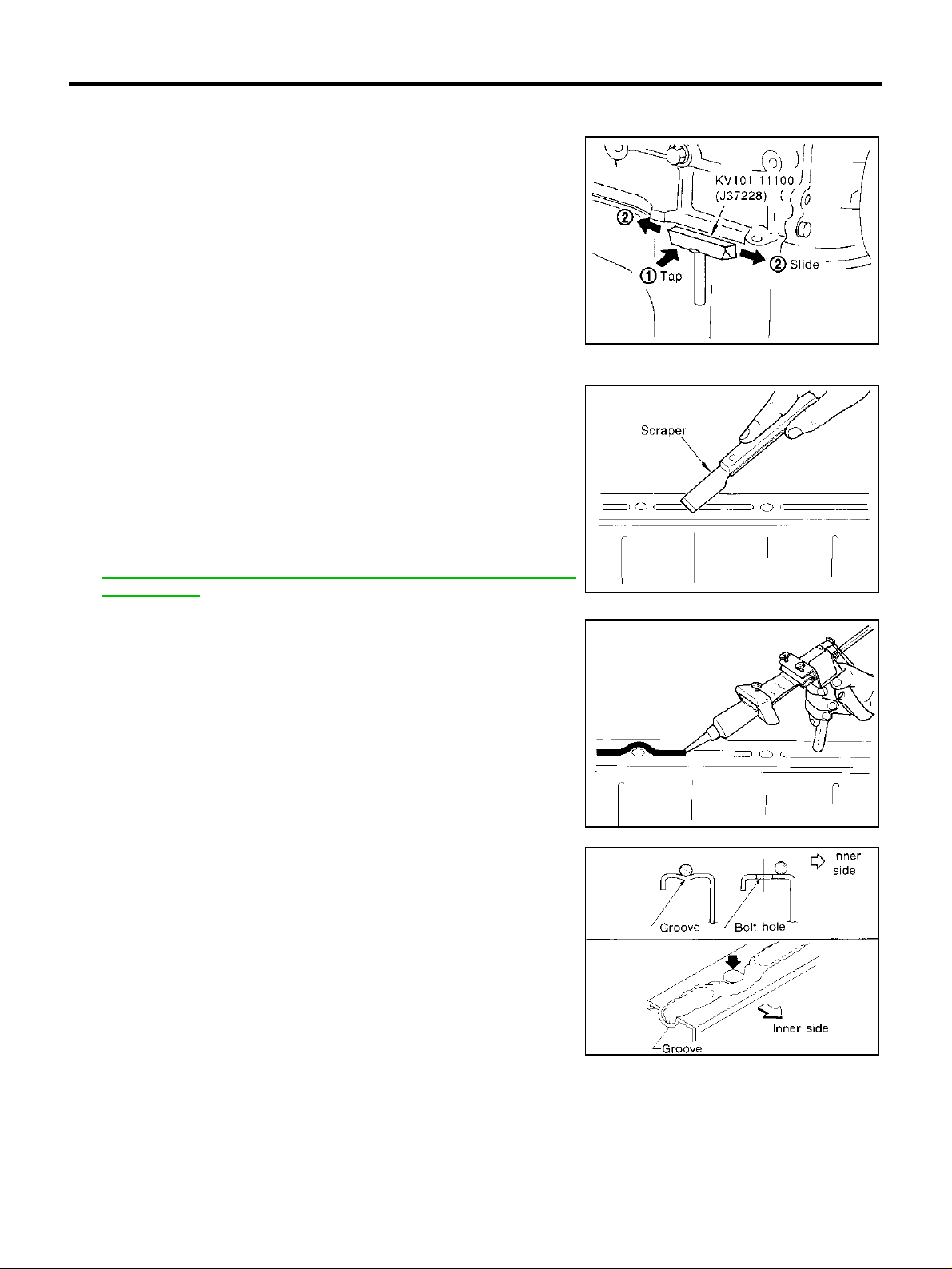
Precautions for Liquid Gasket ABS004RP
REMOVAL OF LIQUID GASKET SEALING
● After removing the mounting bolts and nuts, separate the mating
surface using a seal cutter and remove the old liquid gasket
sealing.
CAUTION:
Be careful not to damage the mating surfaces.
● In areas where the cutter is difficult to use, use a plastic hammer
to lightly tap the areas where the liquid gasket is applied.
CAUTION:
If for some unavoidable reason a tool such as a flat-bladed
screwdriver is used, be careful not to damage the mating
surfaces.
LIQUID GASKET APPLICATION PROCEDURE
1. Using a scraper, remove the old liquid gasket adhering to the
gasket application surface and the mating surface.
● Remove the liqu id gasket completely from the gro ove of the
gasket application surface, mounting bolts, and bolt holes.
2. Wipe the liquid gasket application surface and the mating surface with white gasoline (lighting and heating use) to remove
adhering moisture, grease and foreign materials.
3. Attach the liquid gask et tub e to the tube pres s er.
Use Genuine RTV silicone sealant or equivalent. Refer to
GI-46, "
SEALANTS" .
RECOMMENDED CHEMICAL PRODUCTS AND
PBIC0002E
PBIC0003E
4. Apply the liquid gasket without breaks to the specified location
with the specified dimensions.
● If there is a groove for the liquid ga sket ap plicati on, ap ply the
liquid gasket to the groove.
● As for the bolt holes, normally apply the liquid gasket inside
the holes. Occasionally, it should be applied outside the
holes. Make sure to read the text of this manual.
● Within five minutes of gasket application, install the mating
component.
● If the liquid gasket protrudes, wipe it off immediately.
● Do not retighten after the installation.
● After 30 minu te s o r mo re h ave passed from the installation, fill
the engine oil and engine coolant.
CAUTION:
If there are specific ins tructions in this manual, obs erve
them.
EMA0622D
SEM159F
Revision; 2004 April 2003 Murano
EM-4
PREPARATION
PREPARATION PFP:00002
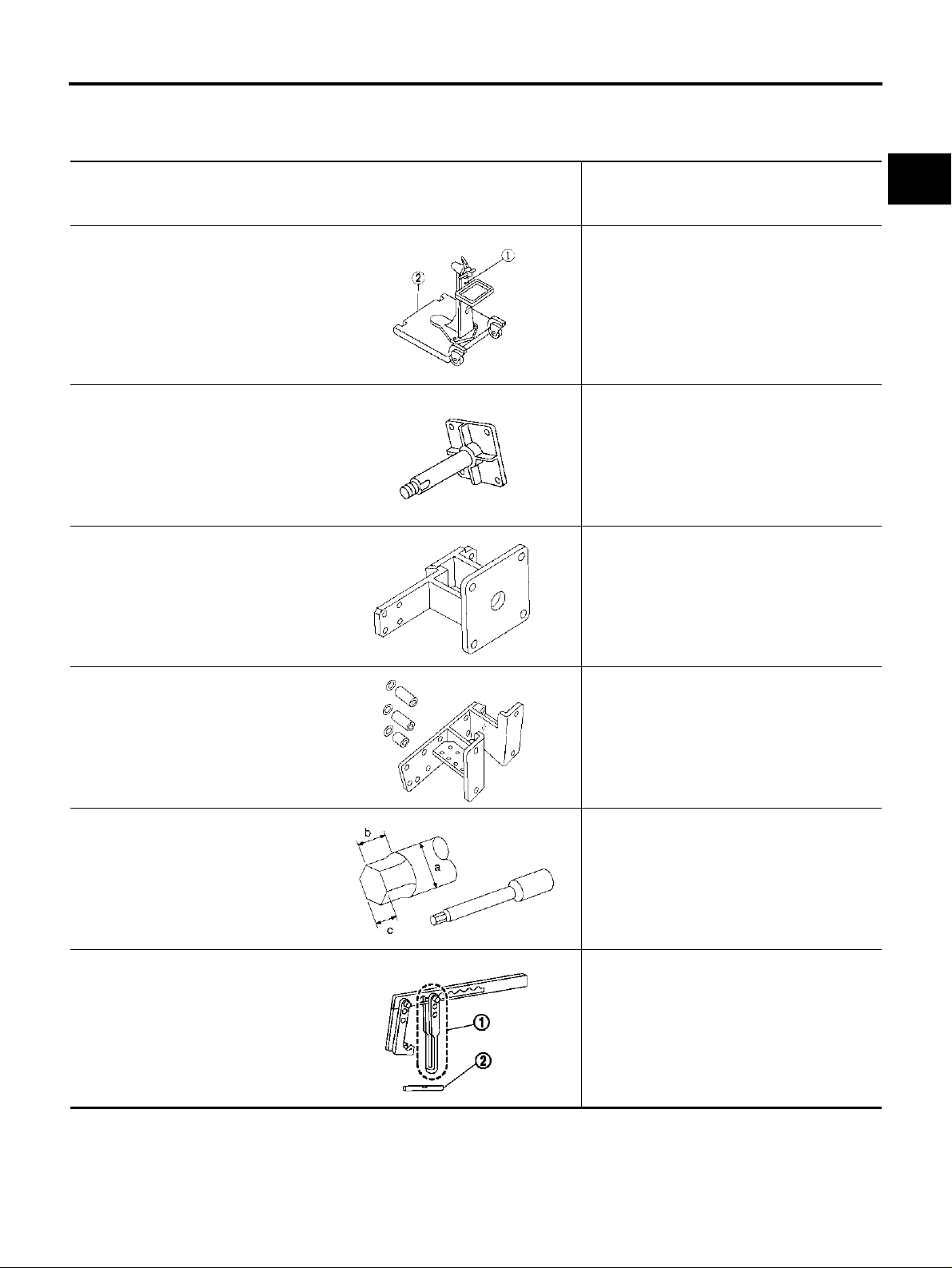
Special Service Tools ABS00325
The actual shapes of Kent-Moore tools may differ from those of special service tools illustrated here.
Tool number
(Kent-Moore No.)
Tool name
Description
A
EM
ST0501S000
(—)
Engine stand assembly
1. ST05011000
(—)
Engine stand
2. ST05012000
(—)
Base
KV10106500
(—)
Engine stand shaft
KV10117000
(J41262)
Engine sub-attachment
KV10117001
(—)
Engine sub-attachment
NT042
NT028
NT373
Disassembling and assembli ng
KV10117000 has been replaced with
KV10117001 (KV10117000 is no longer in
production, but it is usable).
Installing on the cylinder block
C
D
E
F
G
H
I
J
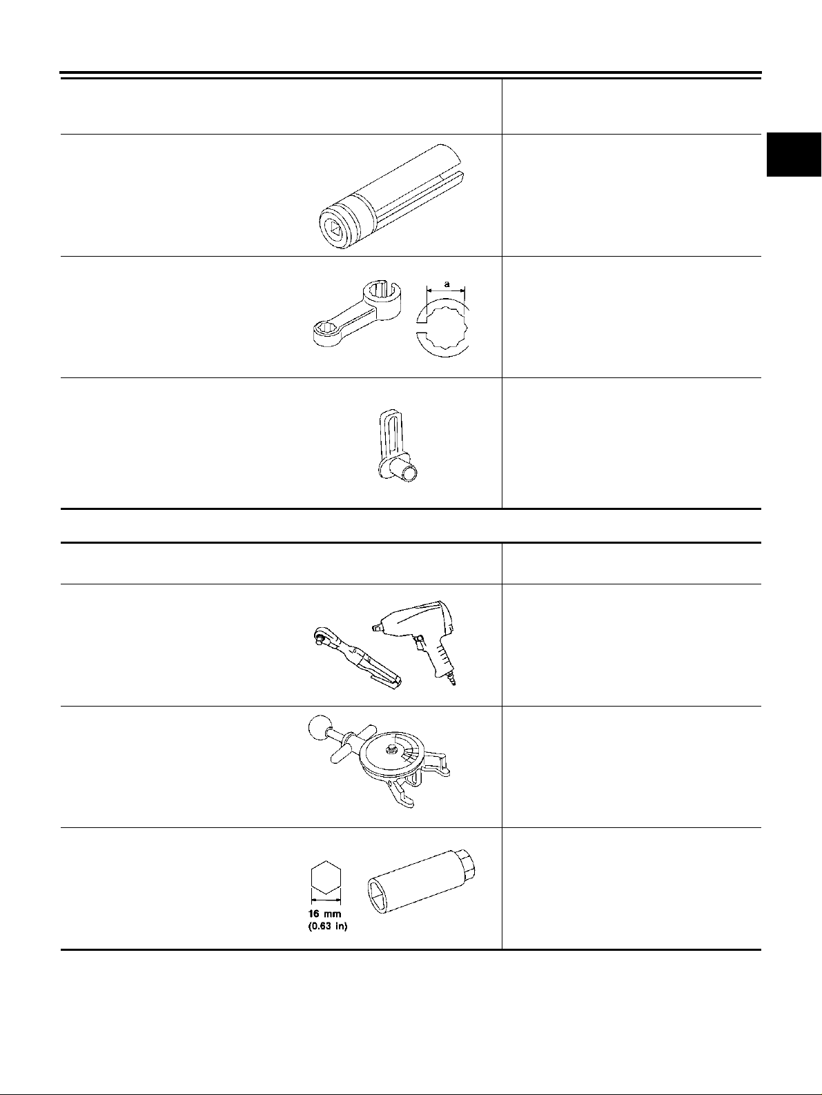
ST10120000
(J24239-01)
Cylinder head bolt wrench
KV10116200
(J26336-B)
Valve spring compressor
1. KV10115900
(J26336-20)
Attachment
2. KV10109230
(—)
Adapter
NT372
NT583
PBIC1650E
Loosening and tightening cylinder head bo lt
a: 13 (0.51) dia.
b: 12 (0.47)
c: 10 (0.39)
Unit: mm (in)
Disassembling valve mechani sm
K
L
M
Revision; 2004 April 2003 Murano
EM-5

Tool number
(Kent-Moore No.)
Tool name
PREPARATION
Description
KV10107902
(J38959)
Valve oil seal puller
1. KV10116100
Valve oil seal puller adapter
(J39386)
Valve oil seal drift
EM03470000
(J8037)
Piston ring compressor
ST16610001
(J23907)
Pilot bushing puller
Removing valve oil seal
S-NT605
Installing valve oil seal
NT024
Installing piston assembly into cylinder bore
NT044
Removing crankshaft pilot bushing
KV10111100
(J37228)
Seal cutter
WS39930000
(—)
Tube presser
KV10112100
(BT8653-A)
Angle wrench
NT045
Removing steel oil pan and rear timing chain
case
NT046
Pressing the tube of liquid gasket
NT052
Tightening bolts for bearing cap, cylinder
head, etc. in angle
NT014
Revision; 2004 April 2003 Murano
EM-6
PREPARATION
Tool number
(Kent-Moore No.)
Tool name
KV10117100
(J3647-A)
Heated oxygen sensor wrench
KV10117200
(J38365)
Heated oxygen sensor wrench
—
(J-45488)
Quick connector release
NT379
NT636
PBIC0198E
Description
Loosening or tightening heated oxygen
sensor
For 22 mm (0.87 in) width hexagon nut
Loosening or tightening rear heated oxygen
sensor
a: 22 mm (0.87 in)
Removing fuel tube quick connectors in
engine room
(Available in SEC. 164 of PARTS CTALOG:
Part No. 16441 6N210)
A
EM
C
D
E
F
G
H
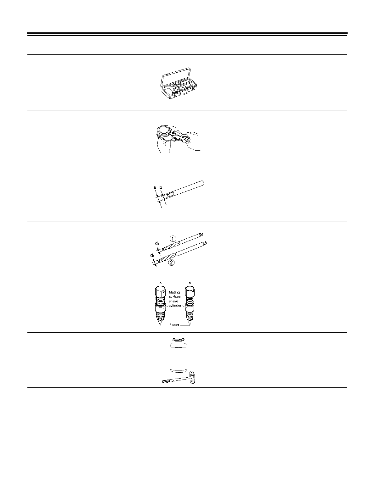
Commercial Service Tools ABS00326
(Kent-Moore No.)
Tool name
Power tool Loosening bolts and nuts
PBIC0190E
(BT3373-F)
Belt tension gauge
AMA126
Spark plug wrench Removing and installing spark plug
Description
Checking drive belt tension
I
J
K
L
M
NT047
Revision; 2004 April 2003 Murano
EM-7
PREPARATION
(Kent-Moore No.)
Tool name
Description
Valve seat cutter set Finishing valve seat dimensions
NT048
Piston ring expander Removing and installing piston ring
NT030
Valve guide drift Removing and installing valve guide
Intake & Exhaust:
a = 9.5 mm (0.374 in) dia.
b = 5.5 mm (0.217 in) dia.
NT015
Valve guide reamer Reaming valve guide with 1 or hole for
oversize valve guide with 2
Intake & Exhaust:
1 = 6.0 mm (0.236 in) dia.
d
2 = 10.2 mm (0.402 in) dia.
d
(J-43897-18)
(J-43897-12)
Oxygen sensor thread cleaner
Anti-seize lubricant (Permatex 133AR
or equivalent meeting MIL
specification MIL-A-907)
NT016
Reconditioning the exhaust system thre ads
before installing a new heated oxygen sensor
(Use with anti-seize lubricant shown below.)
a = J-43897-18 [18 mm (0.71 in) dia.] for
zirconia heated oxygen sensor
b = J-43897-12 [12 mm (0.47 in) dia.] for
titania heated oxygen sensor
AEM488
Lubricating heated oxygen sensor thre ad
cleaning tool when reconditioning exhaust
system threads
AEM489
Revision; 2004 April 2003 Murano
EM-8
NOISE, VIBRATION AND HARSHNESS (NVH) TROUBLESHOOTING
NOISE, VIBRATION AND HARSHNESS (NVH) TROUBLESHOOTING PFP:00003
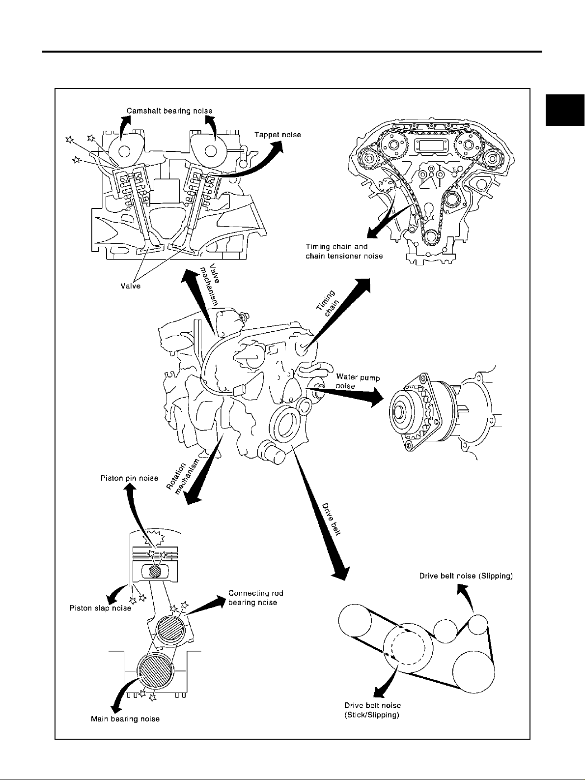
NVH Troubleshooting —Engine Noise ABS00327
A
EM
C
D
E
F
G
H
K
M
I
J
L
SEM706G
Revision; 2004 April 2003 Murano
EM-9
NOISE, VIBRATION AND HARSHNESS (NVH) TROUBLESHOOTING
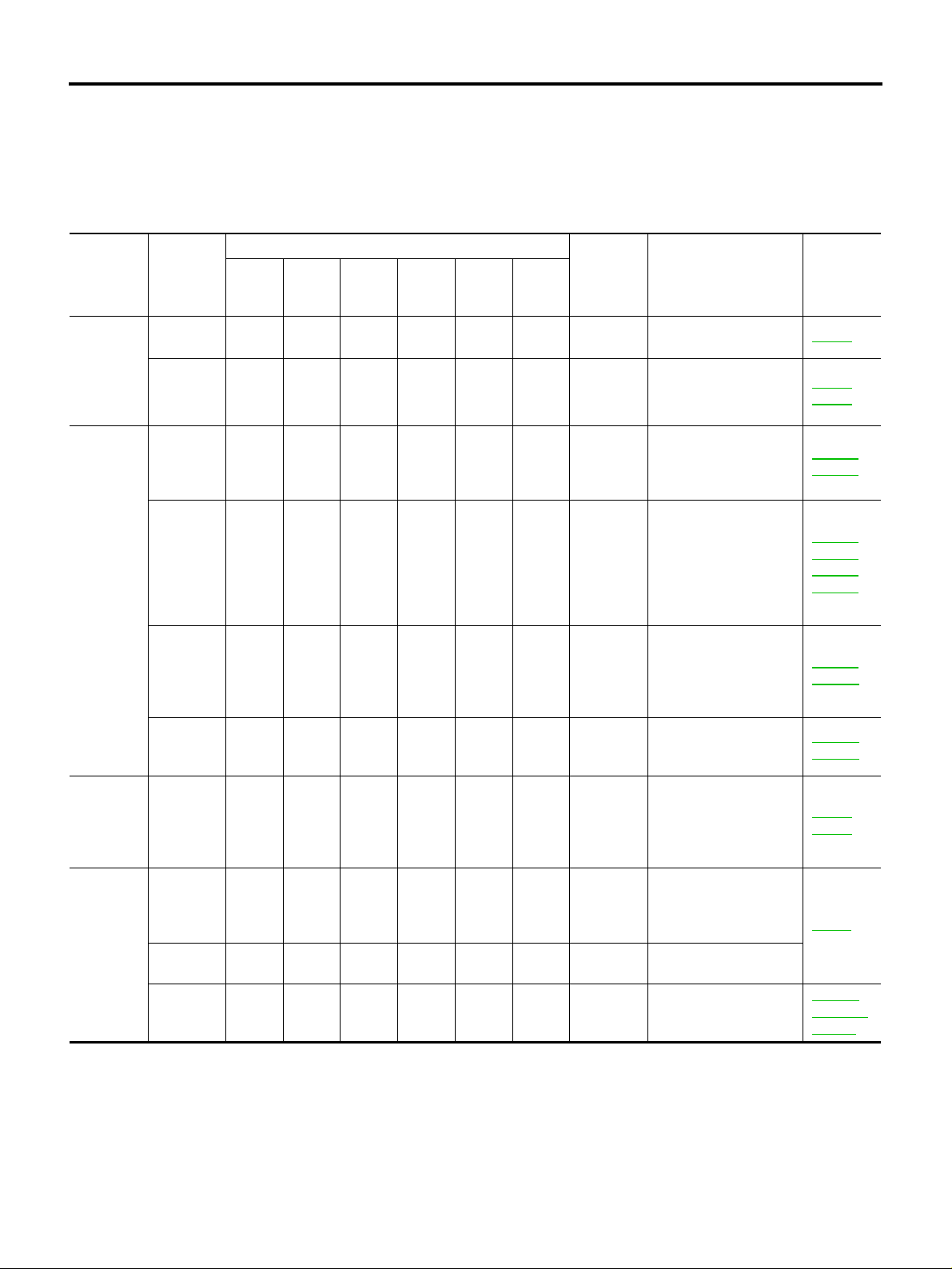
Use the Chart Below to Help You Find the Cause of the Symptom. ABS00328
1. Locate the area where noise occurs.
2. Confirm the type of noise.
3. Specify the operating condition of engine.
4. Check specified noise source.
If necessary, repair or replace these parts.
Operating condition of engine
Location
of noise
Top of
engine
Rocker
cover
Cylinder
head
Crankshaft pulley
Cylinder
block
(Side of
engine)
Oil pan
Front of
engine
Timing
chain
cover
Front of
engine
A: Closely related B: Related C: Sometimes related —: Not related
Type of
noise
Ticking or
clicking
Rattle C A — A B C
Slap or
knock
Slap or
rap
Knock ABCBBB
Knock A B — A B C
T apping or
ticking
Squeaking or fizzing
CreakingABABAB
Squall
Creak
Before
warm-
up
—A—BB—
After
warm-
CA—AB—
A——BB A
AA—BBB
AB—B—C
AB—BAB
up
When
start-
ing
When
idling
When
racing
While
driving
Source of
noise
Tappet
noise
Camshaft
bearing
noise
Piston pin
noise
Piston
slap noise
Connecting rod
bearing
noise
Main
bearing
noise
Timing
chain and
chain tensioner
noise
Drive belts
(Sticking
or slipping)
Drive belts
(Slipping)
Water
pump
noise
Check item
Valve clearance EM-77
Camshaft runout
Camshaft journal clearance
Piston and piston pin
clearance
Connecting rod bushing clearance
Piston-to-bore clearance
Piston ring side clearance
Piston ring end gap
Connecting rod bend
and torsion
Connecting rod bushing clearance (Small
end)
Connecting rod bearing clearance (Big end)
Main bearing oil clearance
Crankshaft runout
Timing chain cracks
and wear
Timing chain tensioner
operation
Drive belts deflection
Idler pulley bearing
operation
Water pump operation
Refer-
ence page
EM-72
EM-72
EM-115
EM-117
EM-119
EM-116
EM-116
EM-116
EM-117
EM-121
EM-122
EM-121
EM-60
EM-54
EM-11
CO-20,
"WATER
PUMP"
Revision; 2004 April 2003 Murano
EM-10
DRIVE BELTS
DRIVE BELTS PFP:02117
Checking Drive Belts ABS00329
WARNING:
Be sure to perform when the engine is stopped.
1. Inspect belts for cracks, fraying, wear and oil. If necessary, replace.
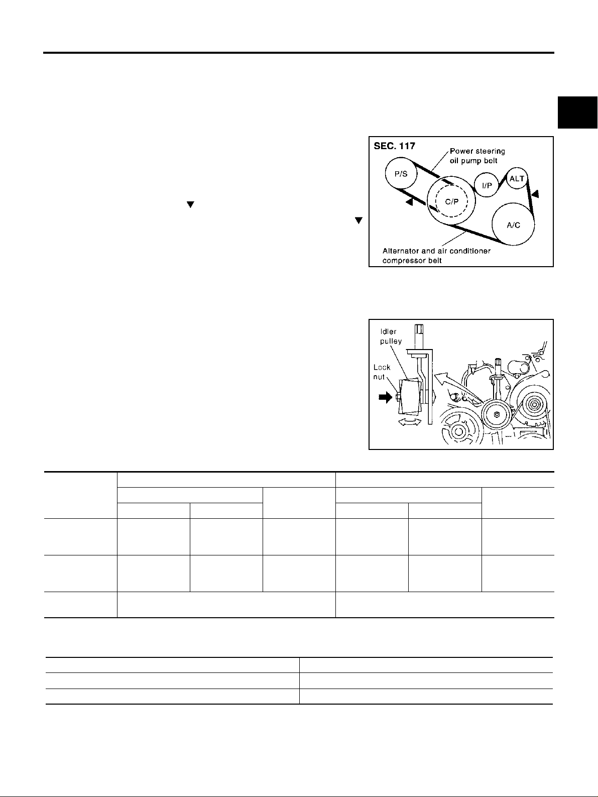
2. Inspect drive belt deflection or tension at a point on the belt midway between pulleys.
● Inspection s hould be done only when en gine is cold, or over
30 minutes after engine is stopped.
● Measure belt tension with tension gauge (BT3373-F or equiv-
alent) at points marked shown in the figure.
● When measuring deflection, apply 98 N (10 kg, 22 lb) at the
marked point.
● Adjust if belt deflectio n exceeds the limit or if belt tension is
not within specifications.
CAUTION:
● When checking belt deflection or tension immediately after installation, first adjust it to the
specified value. Then, after turn ing the cranksha ft two turns or more, re-adjust to the s pecified
value to avoid variation in deflection between pulleys.
● Tighten idler pulley lock nut by hand and measure deflec-
tion or tension without looseness.
PBIC1161E
A
EM
C
D
E
F
G
Belt Deflection and Tension
Deflection adjustment Unit: mm (in) Tension adjustment* Unit: N (kg, lb)
Used belt
Limit After adjustment Limit After adjustment
Alternator and
air conditioner
compressor
Power steering
oil pump
Applied pushing
force
*: If belt tension gauge cannot be installed at check points show n, ch eck dr iv e belt tensi on at different locat ion on th e bel t.
7 (0.28)
11 (0.43)
98 N (10 Kg, 22 lb) —
4.2 - 4.6
(0.17 - 0.18)
7.3 - 8
(0.29 - 0.30)
New belt
3.7 - 4.1
(0.15 - 0.16)
6.5 - 7.2
(0.26 - 0.28)
294 (30, 66)
196 (20, 44)
Used belt
730 - 818
(74.5 - 83. 5,
164 - 184)
495 - 583
(50.5 - 59. 5,
111 - 131)
PBIC1162E
New belt
838 - 926
(85.5 - 94.5,
188 - 208)
603 - 691
(61.5 - 70.5,
135.6 - 155.4)
H
I
J
K
L
M
Tension Adjust me nt ABS0036V
Portion Belt tightening method for adjustment
Power steering oil pump belt Adjusting bolt on power steering oil pump
Alternator and air conditioner compressor belt Adjusting bolt on idler pulley
CAUTION:
● When belt is replaced with a new one, adjust it to value for “New belt” to accommodate for insuffi-
cient adaptability with pulley grooves.
Revision; 2004 April 2003 Murano
EM-11
DRIVE BELTS
● When deflection or tension of belt being used exceeds “Used belt limit”, adjust it to value for
“After adjustment of used belt”.
● When checking belt deflection or ten sio n immedia tely afte r installation, first adj ust it to the spe ci-
fied value. Then, after turni ng th e c rank shaft two turns or more, re-adjus t to th e s pec ifie d v alu e to
avoid variation in deflection between pulleys.
● When installing belt, make sure that it is correctly engaged with pulley groove.
● Keep oil and water away from belt.
● Do not twist or bend belt excessively.
ALTERNATOR AND AIR CONDITIONER COMPRESSOR BELT
1. Remove splash guard (RH).
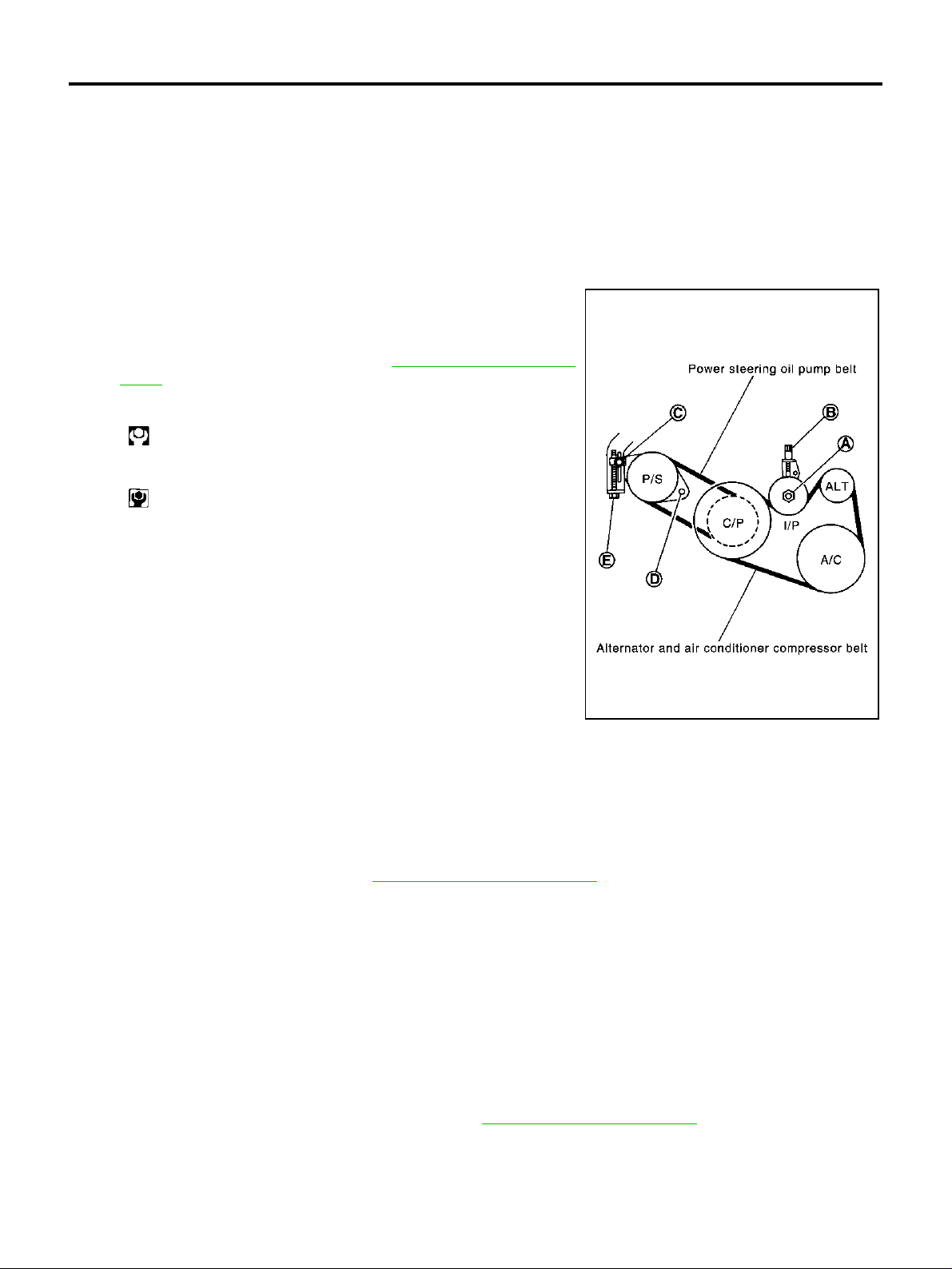
2. Loosen idler pulley lock nut (A) and adjust tension by turning
adjusting bolt (B).
● For specified belt tension, refer to EM-11, "Checking Drive
Belts" .
3. Tighten lock nut (A).
: 30.4 - 39.2 N·m (3.1 - 3.9 kg-m, 23 - 28 ft-lb)
4. Tigh ten adjusting bolt (B).
: 3.9 - 6.9 N·m (0.4 - 0.7 kg-m, 35 - 61 in-lb)
PBIC1163E
POWER STEERING OIL PUMP BELT
1. Remove splash guard (RH).
2. Loosen adjusting bolt (C).
3. Loosen power steering oil pump mounting bolt (D).
● Bolt head (D) is engine rear side.
4. Adjust by turning adjusting bolt (E).
● For specified belt tension, refer to EM-11, "Checking Drive Belts" .
NOTE:
Adjusting b olt (E) is loosened with counter-clockwise rotation.
5. Tighten bolt (C), then bolt (D).
Tightening torque:
Bolt (C) : 24.5 - 31.4 N·m (2.5 - 3.2 kg-m, 18 - 23 ft-lb)
Bolt (D) : 36.3 - 50.0 N·m (3.7 - 5.1 kg-m, 27 - 36 ft-lb)
Removal and Installation ABS0036W
REMOVAL
1. Remove splash guard (RH).
2. Fully loosen each b elt by f ollo wing the gu idel ines in EM- 11, "
air conditioner compressor belt and then power steering oil pump belt.
CAUTION:
Grease is applied to idler pulley adjusting bolt. Be careful to keep grease away from the belt.
Tension Adjustment" . Remove alternator and
Revision; 2004 April 2003 Murano
EM-12

DRIVE BELTS
INSTALLATION
1. Install belts to pulley in reverse order of removal.
CAUTION:
● Make sure belt is correctly engaged with the pulley groove.
● Check for oil and engine coolant on belt and each pulley groove.
2. Adjust belt tension. Refer to EM-11, "
3. Tighten each adjusting bolt and n u t to the specified torque.
4. Make sure that tension of each belt is within the standard.
Tension Adjustment" .
A
EM
C
D
E
F
G
H
K
M
I
J
L
Revision; 2004 April 2003 Murano
EM-13
AIR CLEANER AND AIR DUCT
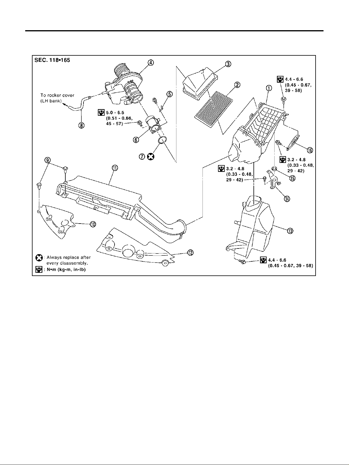
AIR CLEANER AND AIR DUCT PFP:16500 Removal and Installation ABS0033C
1. Air cleaner case (lower) 2. Air cleaner filter 3. Air cleaner case (upper)
4. Air duct assem bl y 5. Harness bracket 6. Mass air flow sensor
7. O-ring 8. PCV hose 9. Clip
10. Radiator cover grill (RH side) 11. Air duct (inlet) 12. Radiator cover grill (LH si de)
13. Resonator 14. Bracket 15. Grommet
16. Bracket
REMOVAL
1. Remove RH and LH both side radiator cover grills.
2. Remove air duct (i nlet).
3. Disconnect harness connector from the mass air flow sensor.
4. Disconnect the tube clamp at the electr ic throttle control actuator and at the mass air flow sensor.
5. Remove PCV hose, air cleaner case (upper) with the mass air flow sensor attached.
6. Remove mass air flow sensor from air cleaner case (upper), as necessary.
CAUTION:
Handle mass air flow sensor with care.
● Do not shock it.
● Do not disassemble it.
● Do not touch its sensor.
7. Remove resonator in the fender, lifting left fender protector, as necessary.
PBIC1806E
Revision; 2004 April 2003 Murano
EM-14

AIR CLEANER AND AIR DUCT
INSTALLATION
Installation is in the reverse order of removal.
CHANGING AIR CLEANER FILTER
1. Unhook the air cleaner case (lower) side clip s and lift up the air cleaner case (upper).
2. Remove the air cleaner filter.
A
EM
C
D
E
PBIC1165E
F
G
H
K
M
I
J
L
Revision; 2004 April 2003 Murano
EM-15
INTAKE MANIFOLD COLLECTOR
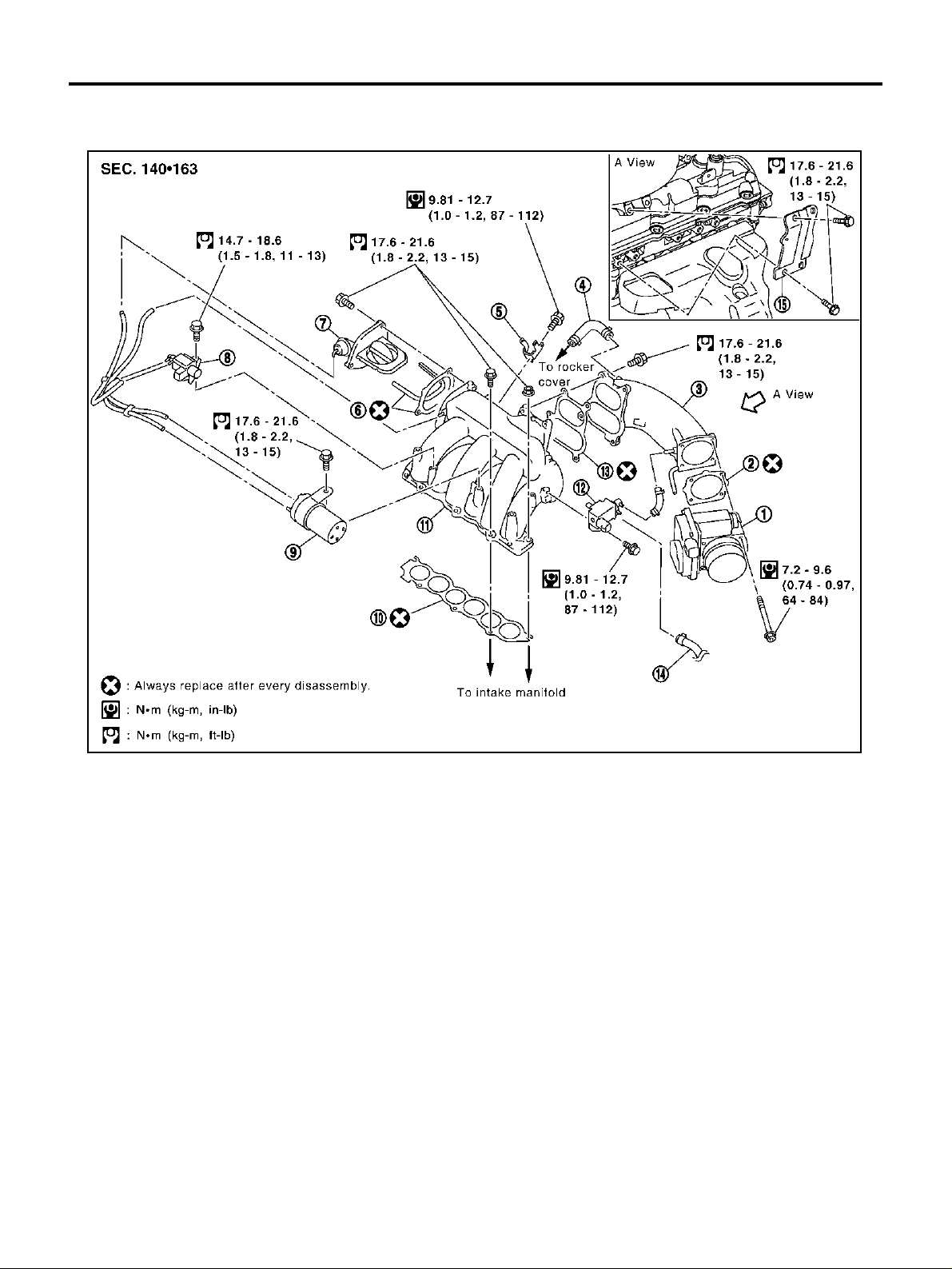
INTAKE MANIFOLD COLLECTOR PFP:14003 Removal and Installation ABS0032E
PBIC1166E
1. Electric th rott le co ntrol act uat or 2. Gasket 3. Intake manifold collector (upp er)
4. PCV hose 5. Harness bracket 6. Gasket
7. Power valve 8. VIAS control solenoid valve 9. Vacuum tank
10. Gasket 11. Intake manifold collector (lower) 12.
13. Gasket 14. EVAP hose 15. Support bracket
EVAP canister purge volume control
solenoid valve
Revision; 2004 April 2003 Murano
EM-16

INTAKE MANIFOLD COLLECTOR
REMOVAL
WARNING:
To avoid the danger of being scalded, never drain the coolant when the engine is hot.
1. Remove engine cover.
2. Drain engine coolant, or when water hose is disconnected,
attach plug to prevent engine coolant leakage. Refer to CO-8,
"Changing Engine Coolant" .
CAUTION:
Perform when engine is cold.
3. Remove air duct. Refer to EM-14, "
DUCT" .
AIR CLEANER AND AIR
A
EM
C
D
E
F
G
PBIC1167E
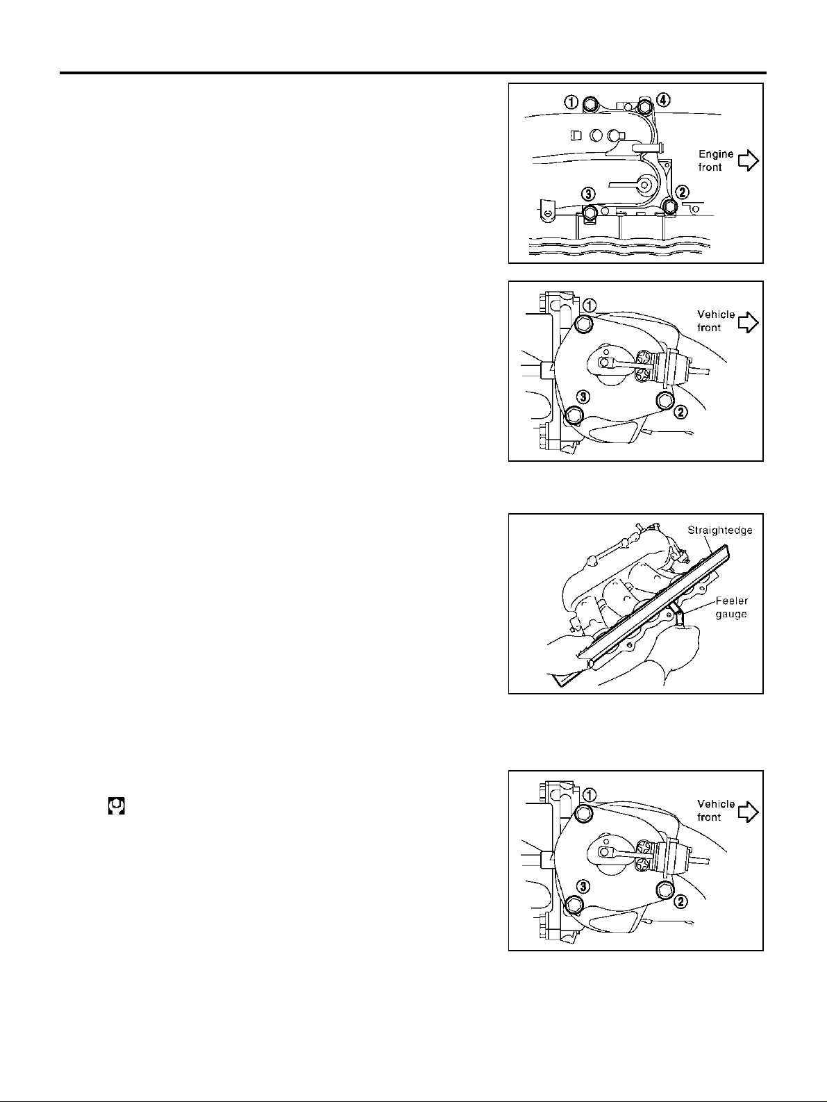
4. Remove electric throttle control actua tor.
● Loosen bolts in the reverse order of that shown in the figure.
CAUTION:
● Handle carefully to avoid any shoc k to the electric throt-
tle control actuator.
● Do not disassemble.
SEM711G
5. Disconnect vacuum h ose and water hose from int ake manifold collector (up per and lower).
6. Disconnect EVAP canister purge volume control solen oid valve mounting bolt f rom intake manifold co llector (lower).
7. Remov e VIAS co ntrol solenoid valve an d vac u um tank.
8. Remove the RH windshield wiper arm and RH front cowl top cover. Refer to EI-21, "
COWL TOP" .
9. Disconnect the power steering hose bracket.
10. Remove intake manifold collector support bracket.
11. Remove PCV hose [between intake manifold collector (upper) and RH rocker cover].
12. Loosen bolts in reverse order of illustration with power tool, and
remove intake manifold collector (upper and lower) assembly
with power tool.
H
I
J
K
L
M
SEM713G
Revision; 2004 April 2003 Murano
EM-17
INTAKE MANIFOLD COLLECTOR
13. Loosen bolts in reverse order of illustration to remove intake
manifold collector (upper) with power tool.
14. Remove power valve in reverse order of illustration.
SEM712G
INSPECTION AFTER REMOVAL
Surface Distortion
● Using straightedge and feeler gauge, inspect the surface distor-
tion of intake manifold collector (lower).
Limit : 0.1 mm (0.004 in)
● If it exceeds the limit, replace the intake manifold collector.
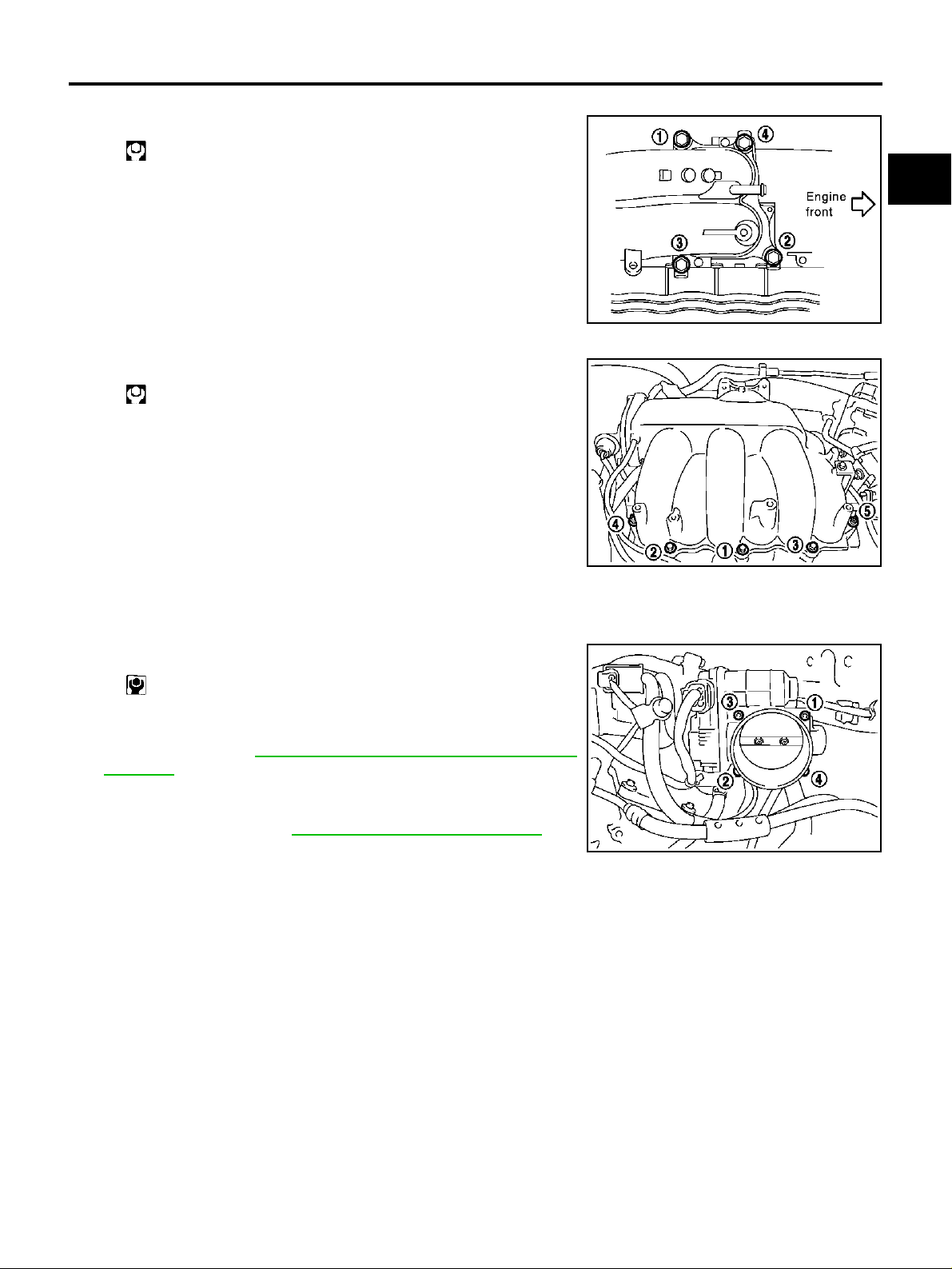
INSTALLATION
● Install in the reverse order of removal paying attention to the following.
Installation of Power Valve
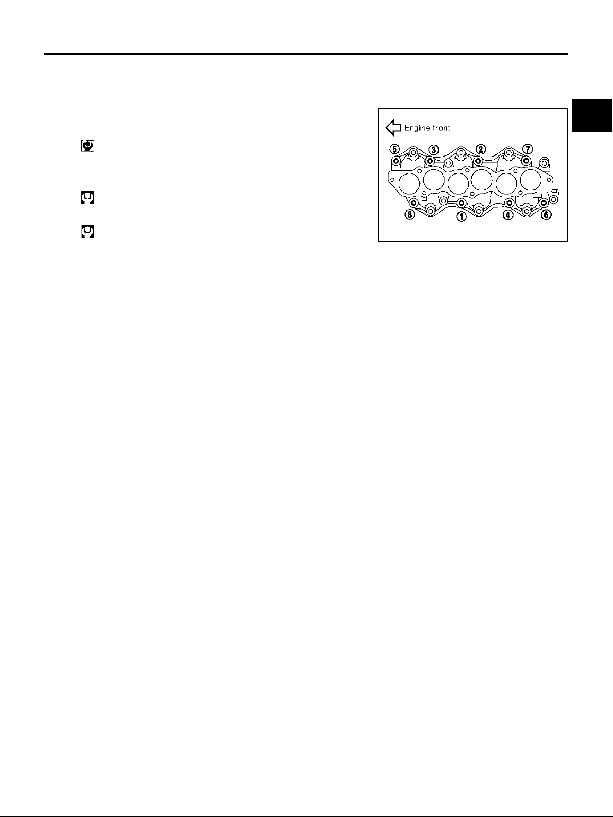
● Tighten in numerical order as shown in the figure.
: 17.6 - 21.6 N·m (1.8 - 2.2 kg-m, 13 - 15 ft-lb)
SEM714G
PBIC1168E
SEM714G
Revision; 2004 April 2003 Murano
EM-18
INTAKE MANIFOLD COLLECTOR
Installation of Intake Manifold Collector (Upper)
● Tighten in numerical order as shown in the figure.
: 17.6 - 21.6 N·m (1.8 - 2.2 kg-m, 13 - 15 ft-lb)
A
EM
C
SEM712G
Installation of Intake Manifold Collector (Lower)
● Tighten in numerical order as shown in the figure.
: 17.6 - 21.6 N·m (1.8 - 2.2 kg-m, 13 - 15 ft-lb)
NOTE:
Tighten mounting bolts to secure gasket (lower), intake manifold collector (lower), gasket (upper).
SEM713G
Installation of Electric Throttle Control Actuator
● Install gasket with three protrusions for installation check facing any direction other than upward or down-
ward.
● Tighten in numerical order as shown in the figure.
: 7.2 - 9.6 N·m (0.74 - 0.97 kg-m, 64 - 84 in-lb)
● Perform the “ Thr o t tle Valve Clos ed Pos it i on Lea rni ng ” wh en har-
ness connecto r of the e lectric throttle co ntrol act uator is discon nected. Refer to EC-64, "
Learning" .
● Perform the “Idle Air Volume Learning” and “Throttle Valve
Closed Position Learning” when the electric throttle control actuator is replaced. Refer to EC-64, "
Throttle Valve Closed Position
Idle Air Volume Learning" .
SEM711G
D
E
F
G
H
I
J
K
L
Revision; 2004 April 2003 Murano
EM-19
M

INTAKE MANIFOLD
INTAKE MANIFOLD PFP:14003 Removal and Installation ABS0033D
1. Intake manifold 2. Gasket
REMOVAL
1. Release fuel pressure. Refer to EC-66, "FUEL PRESSURE RELEASE" .
2. Remove intake manifold collector (upper and lower). Refer to EM-16, "
INT AKE MANIFOLD COLLECTOR"
.
3. Remove fuel tube and fuel injector assembly. Refer to EM-38, "
FUEL INJECTOR AND FUEL TUBE"
4. Loosen bolts an d nuts in reverse ord er of illustration to remove
intake manifold assembly with power tool.
INSPECTION AFTER REMOVAL
Surface Distortion
● Using straightedge and feeler gauge, inspect the surface distor-
tion of each surface on intake manifold.
PBIC1169E
PBIC0778E
Limit : 0.1 mm (0.04 in)
● If it exceeds the limit, replace the intake manifold.
PBIC0870E
Revision; 2004 April 2003 Murano
EM-20
INTAKE MANIFOLD
INSTALLATION
Install in the reverse order of removal paying attention to the following.
Installation of Intake Manifold
● If stud bolt s were rem ov ed , i ns t al l t he m an d ti gh te n t o the to r que
specified below.
: 9.8 - 11.8 N·m (1.0 - 1.2 kg-m, 87 - 104 in-lb)
● Tighten all mounting b olts and n uts to spec ified to rque in t wo or
more steps in numerical order shown in figure.
A
EM
C
1st step
: 4.9 - 9.8 N·m (0.5 - 1.0 kg-m, 4 - 7 ft-lb)
2nd step and after
: 26.5 - 31.4 N·m (2.7 - 3.2 kg-m, 20 - 23 ft-lb)
PBIC0778E
D
E
F
G
H
I
J
K
Revision; 2004 April 2003 Murano
EM-21
L
M
EXHAUST MANIFOLD AND THREE WAY CATALYST
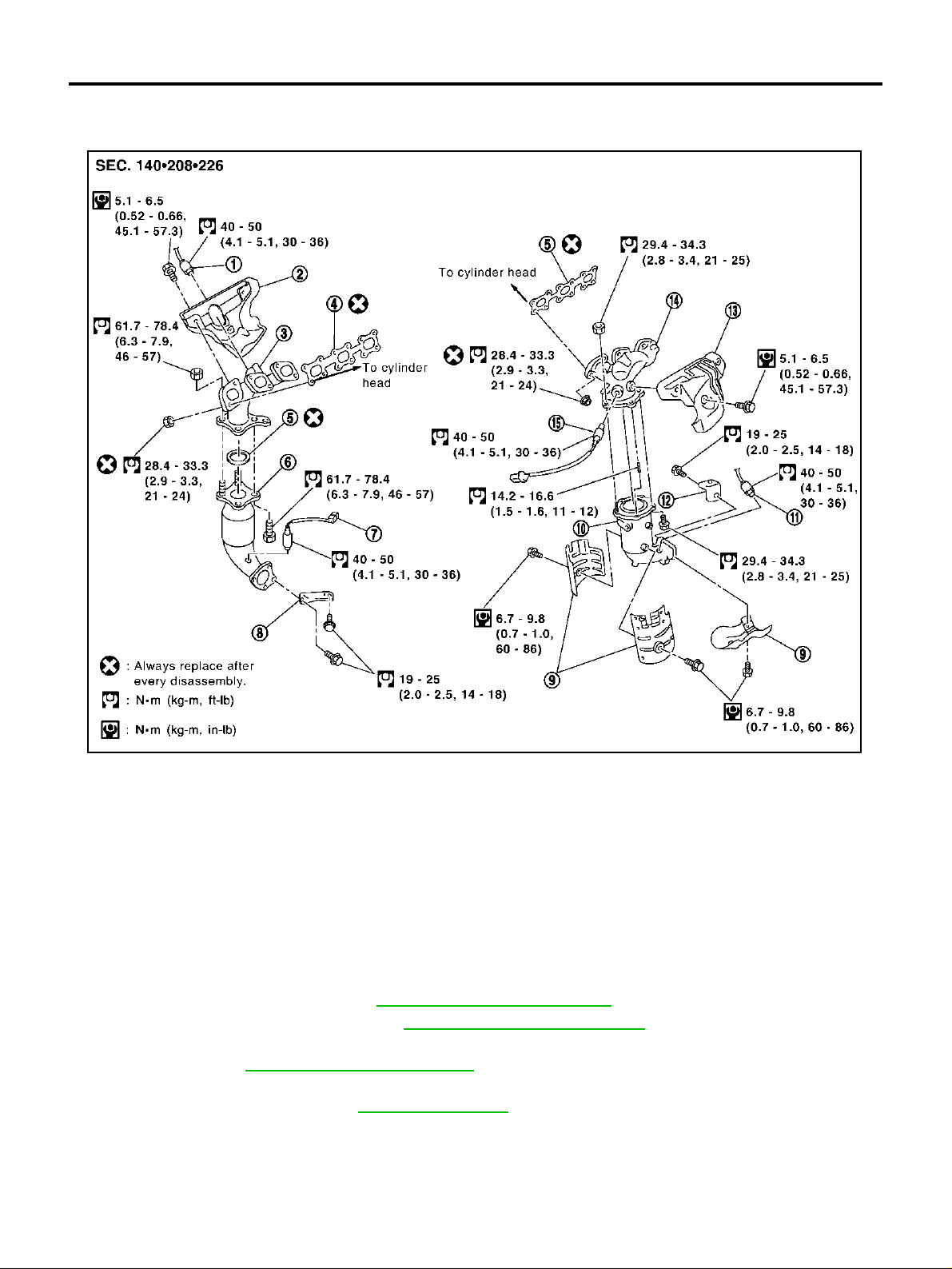
EXHAUST MANIFOLD AND THREE WAY CATALYST PFP:14004 Removal and Installation ABS0032G
PBIC1170E
1. Heated oxygen sensor 1 (bank 1) 2. Exhaust manifold cover 3. Exhaust manifold (RH bank)
4. Gasket 5. Gasket 6.
7. Hea ted oxyge n sensor 2 (bank 1) 8. Support (RH) 9. Three way catalyst heat shiel d
Three way catalyst (manifold) (LH
10.
bank)
13. Exhaust manifold cover 14. Exhaust manifold (LH bank) 15. Heated oxygen sensor 1 (bank 2)
11. Heated oxygen sensor 2 (bank 2) 12. Support (LH)
Three way catalyst (manifold) (RH
bank)
REMOVAL
WARNING:
● Perform the work when the exhaust and cooling system have completely cooled down.
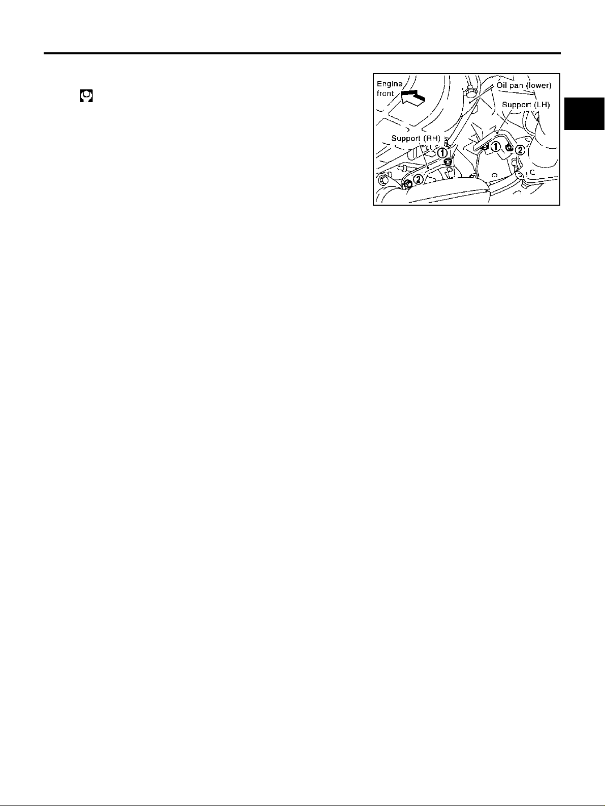
● When removing the engine mo unting through bolts and nuts, lift the e ngine up slightl y for safety
with a transmission jack. Refer to EM-95, "
1. Remove the exhaust front tube. Refer to EX-3, "
2. Remove rear engine mount insulator (2WD models) (when RH exhaust manifold and three way catalyst is
removed). Refer to EM-95, "
ENGINE ASSEMBLY" .
3. Remove the RH windshield wiper arm and RH front cowl top cover (when RH exhaust manifold and three
way catalyst i s removed). Refer to EI-21, "
ENGINE ASSEMBLY" .
Removal and I nstallation" .
COWL TOP" .
Revision; 2004 April 2003 Murano
EM-22

EXHAUST MANIFOLD AND THREE WAY CATALYST
4. Remove heated oxygen sensor 1 and 2 on both LH and RH
bank.
a. Remove harness connector of each heated oxygen sensor, and
disconnect th e harness from the bracket and middle clamp.
b. Remove both heated oxygen sensors with heated oxygen sen-
sor wrench [special service tool: KV10117100 (J3647-A) or
KV10117200 (J38365)].
CAUTION:
● Be careful not to damage heated ox ygen sensor.
● Discard any heated oxygen sensor which has been
dropped from a height of more tha n 0. 5 m (19 .7 in) onto a
hard surface such as a concrete floor; replace with a new sensor.
5. Remove the exhaust m anifold covers and the three way catalyst heat shields.
6. Remov e b ol ts in th e r ev ers e o rde r of illustration to re mo ve three
way catalyst supports (RH and LH).
A
EM
C
PBIC1182E
D
E
F
G
PBIC1174E
7. Remove the three way catalyst (manifold) (RH bank) and three way catalyst (manifold) (LH bank) by loosening the bolts first and then removing the nuts.
8. Remove the exhaust manifolds.
● Loosen the nuts in the reverse order as shown.
PBIC1171E
H
I
J
K
L
M
PBIC1172E
Revision; 2004 April 2003 Murano
EM-23

EXHAUST MANIFOLD AND THREE WAY CATALYST
INSPECTION AFTER REMOVAL
Surface Distortion
● Use a reliable strai ghtedge and feeler gaug e to check the flat-
ness of the exhaust manifold mating surfaces.
Limit : 0.3 mm (0.012 in)
● If it exceeds the limit, replace the exhaust manifold.
PBIC1173E
INSTALLATION
Installation is in the reverse order of removal paying attention to the following.
CAUTION:
● When using the h eated oxy gen se nso r wrenc h [s pecia l se rvice tool : KV 10117200 (J38365) ], ti ghte n
to the middle of specified torque range, because the length of the tool may in crease the actual
tightness. Do not tighten to th e maximum specified torque range.
● Before installing a heated oxyge n sensor, clean the threads on the exhaust manifold using the
oxygen sensor thread cleaner tool (commercial service tool), and apply anti-seize lubricant.
● Do not over-torque the heated oxygen sensors. Doing so may cause damage to the heated oxygen
sensors.
Exhaust Manifold
● Install the exhaust manifold nuts in the numerical order as
shown.
PBIC1171E
PBIC1172E
Revision; 2004 April 2003 Murano
EM-24
EXHAUST MANIFOLD AND THREE WAY CATALYST
Three Way Catalyst Supports
Install in the numerical order as shown.
: 19 - 25 N·m (2.0 - 2.5 kg-m, 14 - 18 ft-lb)
A
EM
C
PBIC1174E
D
E
F
G
H
I
J
K
Revision; 2004 April 2003 Murano
EM-25
L
M

OIL PAN AND OIL STRAINER
OIL PAN AND OIL STRAINER PFP:11110 Removal and Installation ABS0036T
PBIC1175E
1. Gasket 2. Upper oil pan 3. Baffle plate
4. O-ring 5. Oil pressure switch 6. Relief valve
7. Oil cooler 8. Oil cooler co nnector 9. Oil filter
10. Gasket 11. Oil strainer 12. Gasket
13. Drain plug 14. Lower oil pan 15. Rear cover plate
Heated oxygen sensor (bank 2) har-
16.
ness clamp (2WD models)
17. Crankshaft position sensor (POS)
REMOVAL
2WD Model
WARNING:
Do not remove the oil pan until the exhaust system and cooling system have completely cooled off.
CAUTION:
When removing the upper oil pan from the engine, first remove the crankshaft position sensor (POS).
Be careful not to damage sensor edges or signal plate teeth.
1. Remove splash guard (RH).
2. Remove the front RH road wheel and tire with power tool.
3. Drain engine oil. Refer to LU-8, "
4. Drain engine coolant. Refer to CO-8, "Changing Engine Coolant" .
CAUTION:
● Perform when engine is cold.
● Do not spill engine coolant on the drive belts.
5. Remove oil filter. Refer to LU-9, "
CAUTION:
Do not spill engine oil on the drive belts.
Changing Engine Oil" .
OIL FILTER" .
Revision; 2004 April 2003 Murano
EM-26
OIL PAN AND OIL STRAINER
6. Remove oil cooler and water pipes. Refer to LU-10, "OIL COOLER" .
7. Remove drive belts. Refer to EM-11, "
8. Remove A/C compressor with piping connected, and temporarily secure it aside. Refer to ATC-151,
"Components" .
9. Remove exhaust front tube. Refer to EX-3, "
10. Remo ve the he at ed ox yg en sen so r 2 ( ban k 2 ) an d r emov e t he thr e e way c atalyst (manifold) (bank 2) fr om
the exhaust manifold. Refer to EM-22, "
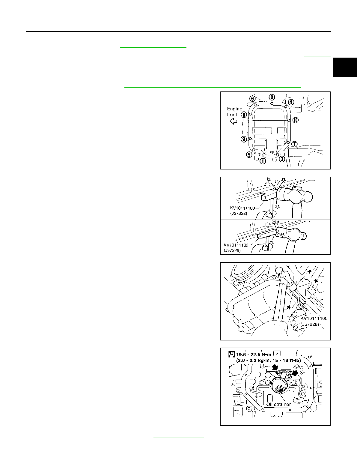
11. Loosen lower oil pan bolts with power tool in reverse order of
illustration to remove.
DRIVE BELTS" .
EXHAUST SYSTEM" .
EXHAUST MANIFOLD AND THREE WAY CATALYST" .
A
EM
C
D
E
12. Insert a seal cutter (s pecial service tool) betw een the lower oil
pan and the upper oil pan.
CAUTION:
● Be careful not to damage the mating surface.
● Do not insert a screwdriver, this will damage the ma ting
surfaces.
13. Slide seal cutter (special servi ce tool) b y tapping on the side of
the tool with a hammer. Remove lower oil pan.
PBIC0782E
SEM365E
SEM960F
F
G
H
I
J
K
L
M
14. Remove oil strainer.
SEM575GA
15. Remove the oil pressure switch. Refer to LU-6, "
Inspection" .
16. Remove crankshaft position sensor (POS).
Revision; 2004 April 2003 Murano
EM-27
OIL PAN AND OIL STRAINER
CAUTION:
● Handle carefully to avoid dropping and shocks.
● Do not disassemble.
● Do not allow metal powder to adhere to magnetic part at sensor tip.
● Do not place sensors in a location where they are exposed to magnetism.
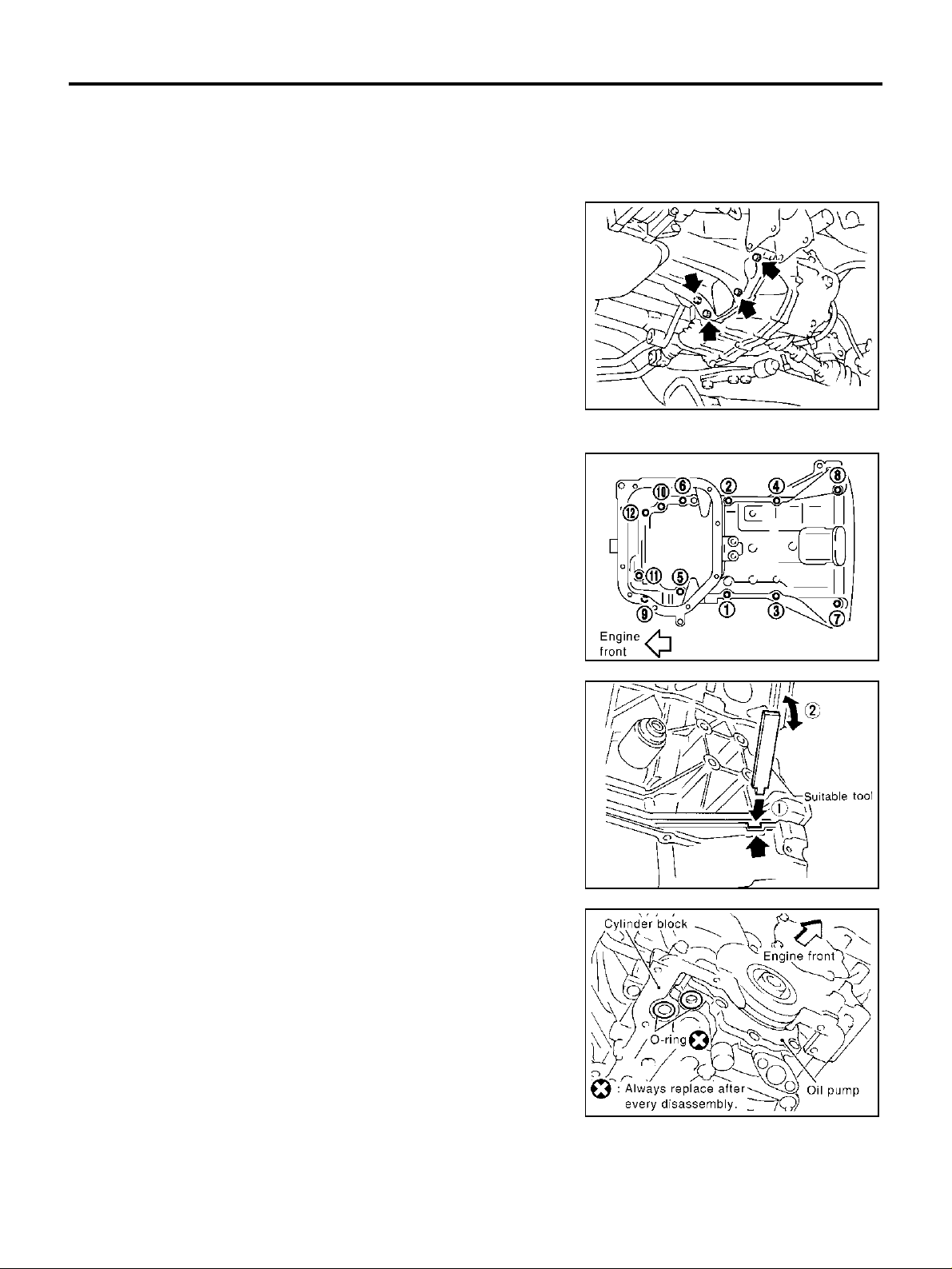
17. Remove the four engine-to-transaxle bolts.
18. Remove upper oil pan.
● Loosen bolts in reverse order as shown with power tool.
SEM949G
19. Insert an appropriate size tool into the no tc h of th e up pe r oil pan
as shown (1).
Pry off the upper oil pan by moving the tool up and down as
shown (2).
20. Remove O-rings from the bottom of the cylinder block and oil
pump body.
PBIC1636E
SEM155F
PBIC1144E
Revision; 2004 April 2003 Murano
EM-28
OIL PAN AND OIL STRAINER
21. Remove oil pan gaskets.
PBIC1145E
AWD Model
WARNING:
Do not remove the oil pan until the exhaust system and cooling system have completely cooled off.
CAUTION:
When removing the upper oil pan from the engine, first remove the crankshaft position sensor (POS).
Be careful not to damage sensor edges or signal plate teeth.
1. Remov e engine assembly from vehicle, and separate fro nt suspension member, transaxle a nd transfer
assembly from engine. Refer to EM-95, "
2. Install engi ne slingers. Refer to EM-100, "
3. install engine sub-attachment to right side of cylinder block, then lift engine, and mount it onto the engine
stand. Refer to EM-100, "
4. Drain engine oil. Refer to LU-8, "
5. Remove oil filter. Refer to LU-9, "
CYLINDER BLOCK" .
Changing Engine Oil" .
OIL FILTER" .
CAUTION:
Do not spill engine oil on the drive belt.
6. Remove oil cooler and water pipes. Refer to LU-10, "
7. Remove the heated ox yg en senso r 2 (b an k 2) an d re mov e the t hre e wa y c at al ys t ( man ifo ld ) ( bank 2) fr om
the exhaust manifold. Refer to EM-22, "
8. Loosen lower oil pan bolts with power tool in reverse order of
illustration to remove.
Removal and I nstallation" .
CYLINDER BLOCK" .
OIL COOLER" .
EXHAUST MANIFOLD AND THREE WAY CATALYST" .
A
EM
C
D
E
F
G
H
I
J
9. Insert a s eal cutter (special servi ce tool) between the lower oil
pan and the upper oil pan.
CAUTION:
● Be careful not to damage the mating surface.
● Do not insert a screwdriver, this will damage the ma ting
surfaces.
K
L
M
PBIC0782E
SEM365E
Revision; 2004 April 2003 Murano
EM-29

OIL PAN AND OIL STRAINER
10. Slide seal cutter (special service tool) by tapping on the side of
the tool with a hammer. Remove lower oil pan.
11. Remove oil strainer.
SEM960F
12. Remove the oil pressure switch. Refer to LU-6, "
Inspection" .
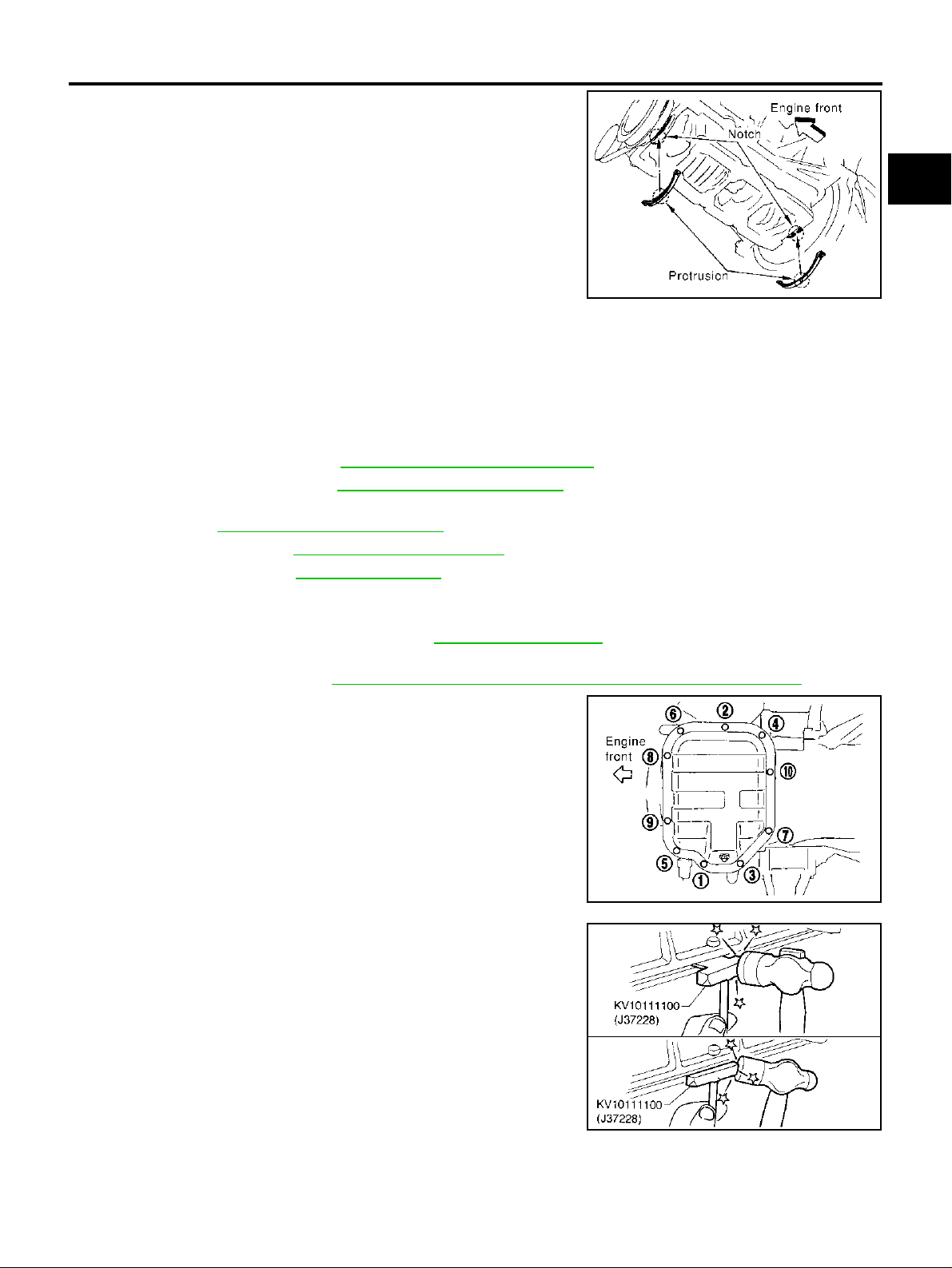
13. Remove upper oil pan.
● Loosen bolts in reverse order as shown with power tool.
14. Insert an appro priate size tool into the no tc h of th e up pe r oil pan
as shown (1).
Pry off the upper oil pan by moving the tool up and down as
shown (2).
SEM575GA
PBIC1636E
SEM155F
Revision; 2004 April 2003 Murano
EM-30
 Loading...