

Page 1
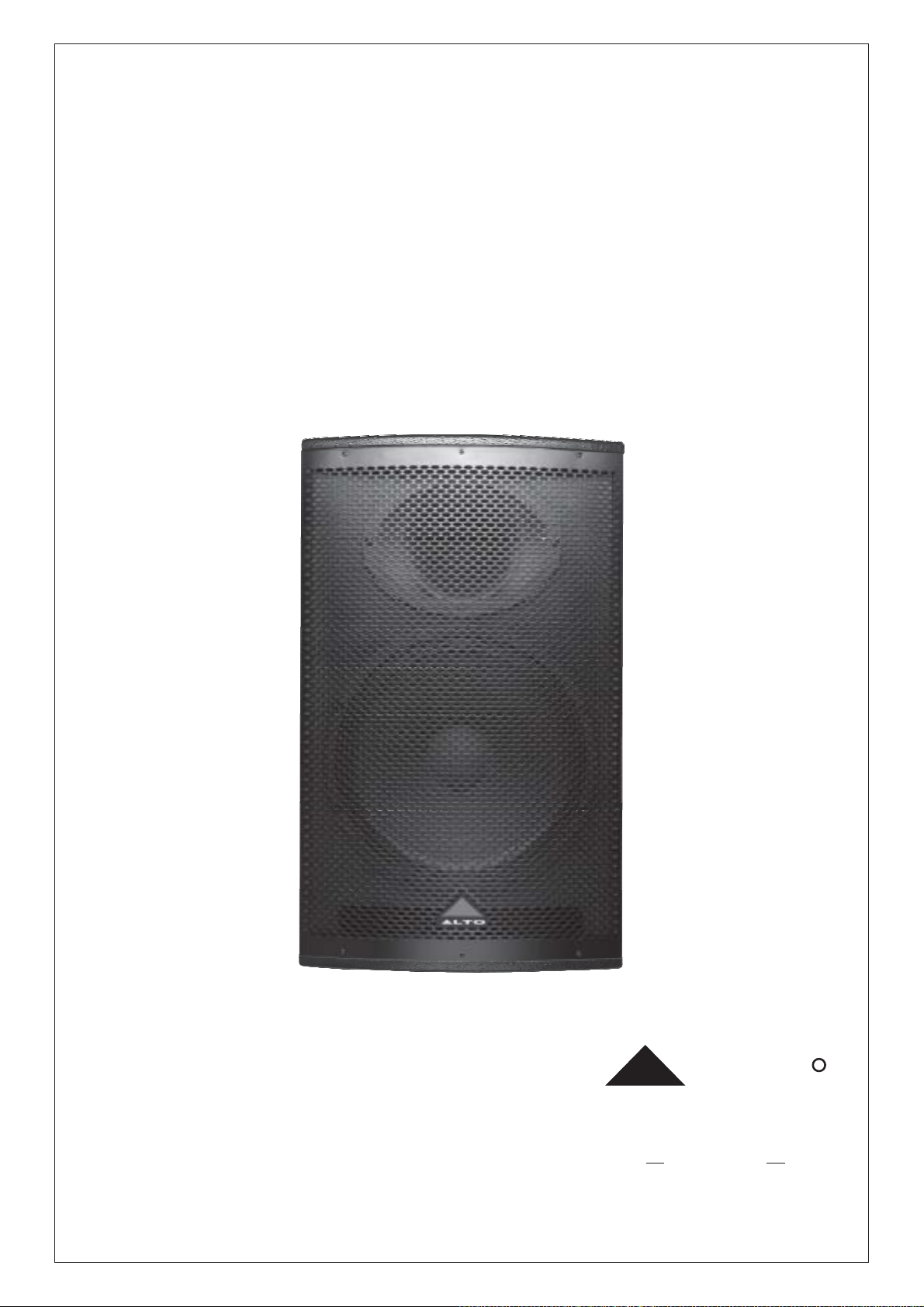
MS Series
User's Manual
LTO
www.altoproaudio.com
Version 1.0 March 2006
English
R
Page 2
SAFETY INSTRUCTIONS
CAUTION
RISK OF ELECTRIC SHOCK
DO NOT OPEN
"Electric discharge"
This symbol, alert you to the presence of uninsulated dangerous voltage inside the product which constitutes aenclosure,
risk of electric shock.
"Exclamatory point"
This symbol, alert the user to the presence of important operating and maintenance instructions the owner's manualin
included to the product.
Disposing of this product should not be placed in municipal waste and should Separate collection.be
1. Read Instructions
All the safety and operation instructions should be read before using the product and retain them for future reference.
2. Water & Moisture
This product should not be used near water and will be protect from atmospheric agents in fixed or temporary installations.
3. Heat
This product should be situated away from heat sources such as radiators, or other devices which produce heat.
4. Liquid Entry
Care should be taken so that liquids are not spilled into the product and that objects do not fall on.
5. Service Assistance
This product should be serviced only by qualified service personnel when :
a. Liquids has spilled or objects have fallen into this product, or
b. This product has been exposed to rain, or
c. This product does not appear to operate normally or exhibits change in performance, or been dropped or itshas
cabinet / chassis damaged.
6. Package
The package of this product has been tested, inspect the package before open, if any damage is found, notify to
your dealer.
7. Hearing
This product produce high acoustic levels may cause permanent hearing loss, (SPL in for a defined period of time).
8. Installations
This product should be installed on the floor with a specific stand, according to the max weight, or in suspension
with a five points included in the cabinet (M10 1.5PH Length 30mm).
The suspension of more speaker cabinet in a vertical array is NOT advised.
1
Page 3

TABLE OF CONTENTS
1. INTRODUCTION.......................................................................................................................................................3
2. FEATURES................................................................................................................................................................4
3. QUICK START...........................................................................................................................................................5
4. CONTROL ELEMENTS............................................................................................................................................7
5. INSTALLATION AND CONNECTION......................................................................................................................9
6. TECHNICAL SPECIFICATION................................................................................................................................10
2
Page 4

1. INTRODUCTION
Thank you for purchasing LTO MS series speaker system. This series includes MS series cabinet and LTO MS1
speaker modeller.
MS series cabinet is specifically designed for use in hi-quality performance site and the precise sound reinforcement
commercial place. It includes five full range cabinets (MS12, MS15, MS152, MS153, and MS154) and two subwoofers
(MS15S, MS18S). This series uses trapezium configuration which greatly decreases the resonance of the standing
wave in the cabinet. The cabinet uses hi-density matrix spray-paint technics and the bottom bracket design which
makes mounting quickly and flexibly. HF compression driver and vented LF for fully professional performance.
LTO MS1 speaker modeller is designed for the use together with MS series cabinet. It has built-in 16 EQ curves
which are suitable for different application and are convenient for users to select presets as need. When the
non-professionals use it, they can obtain optimal effects. It uses external power which can effectively decreases the
power noise. Not only can it be used with MS series cabinet, but also can be used as a EQ together with the other
sound equipment.
Although the operation of MS series speaker system is very simple, to obtain the optimal effects please read this
manual carefully before operation.
3
Page 5

2. FEATURES
Trapezium configuration decreases the resonance of the standing wave in the cabinet.
The cabinet uses hi-density matrix spray-paint technics
The bottom bracket design makes mounting quickly and flexibly.
HF compression driver and vented LF for fully professional performance.
Steep slope of 12dB/octave crossover for a cleaner signal with finer detail
Built-in 16 EQ curves which are suitable for different application.
external power which can effectively decreases the power noise
4
Page 6

3. QUICK START
Make all initial connections with all the equipment powered off, and ensure that all the main volume controls are
turned completely down.
-. For Passive Full-range Speakers
1). Connect one side of the speaker cable to the OUTPUT CHA/CHB or Binding Post of your stereo power amplifier
and the other side to the INPUT socket of your speaker cabinet.
2) Connect the input terminal of LTO MS1 with the AUX SEND of mixer( or the similar terminal). Connect its output
terminal with the AUX RETURN of the mixer. Then select the preset as need.
3). Complete other connections as illustrated.
4). Turn on your mixer and MS1 first, then the stereo power amplifier.
5). Turn up the volume controls of your amplifier to about 70%.
6). Use PFL function to get the proper input level for the mixer, and adjust the Main Mix Level control to manipulate
the output level.
7). After using, turn off your stereo power amplifier first, then the mixer and Ms1.
Tripod
Mount
QUICK START
MS Passive Full-range Speakers
speaker cable
Stereo
Power Amplifier
Left
Main Mix
Output
speaker cable
Right
Main Mix
Output
Tripod
Mount
Mixer
5
Page 7

-. For Passive Subwoofer & Satellite Speakers
1). Connect one side of speaker cable to the Output CHA/CHB or Binding Post of your stereo power amplifier and the
other
side to the Input socket of your subwoofer, with the second speaker cable connect the Output of the subwoofer to
the Input of satellite.
2) Connect the input terminal of LTO MS1 with the AUX SEND of mixer ( or the similar terminal). Connect its output
terminal with the AUX RETURN of the mixer. Then select the preset as need.
3). Complete other connections as illustrated.
4). Turn on your mixer and MS1 first, then the stereo power amplifier.
5). Turn up the volume controls of your amplifier to about 70%.
6). Use PFL function to get the proper input level for the mixer, and adjust the Main Mix Level control to manipulate
the output level.
7). After using, turn off your stereo power amplifier first, then the mixer and Ms1.
QUICK START
MS Passive Subwoofer & Satellite Speakers
pole
Mount
Speaker Cable
Speaker Cable
Mixer
Stereo
Power Amplifier
Left
Main Mix
Output
Speaker Cable
pole
Mount
Speaker Cable
Right
Main Mix
Output
6
Page 8

4. CONTROL ELEMENTS
4.1MS SERIES CABINET
- PASSIVE FULL-RANGE Speaker for MS12 / MS15 / MS152 / MS153/MS154
(1) INPUT: Receive the power coming from an external power amplifier (SPK +1/-1 connected; +2/-2 not connected).
(2) THRU: Direct LINK for connect in parallel a second speaker cabinet (SPK +1/-1 connected; +2/-2 not connected).
LTO
MS12
SOUND REINFORCEMENT SPEAKER SYSTEM
POWER HANDLING:
CONTINOUS - 200 Watts
PEAK - 400 Watts
IMPEDANCE:
8 Ohms
MODEL
SERIAL
DESIGNED AND DEVELOPMENT IN ITALY
INPUT
R
THRU
LINK
(1) (2)
- PASSIVE SUBWOOFER Speaker for MS15S / MS18S
(1) INPUT: Receive the power coming from an external amplifier (SPK +1/-1 connected;+2/-2 not connected).
(2) OUTPUT: Power output for satellite speaker, under passive crossover filtered at 125Hz (SPK +1/-1 connected;
+2/-2 not connected).
LTO
MS15S
SOUND REINFORCEMENT SPEAKER SYSTEM
POWER HANDLING:
CONTINUOUS - 400 Watts
PEAK - 800 Watts
IMPEDANCE:
8 ohms nominal
MODEL
SERIAL
DESIGNED AND DEVELOPMENT IN ITALY
INPUT
R
THRU
LINK
(1) (2)
7
Page 9

4.2 LTO MS1 SPEAKER MODELLER
- THE FRONT PANEL
R
LTO
CLIP
0dB
MIN MAX
GAIN
MS1
SPEAKER MODELLER
ROCK & ROLL+SUB
ACOUSTIC
LOUDNESS
ARENA+SUB
CONCERT HALL
ANTIRUMBLE
DRUM KICK
JAZZ CLUB+SUB
FLAT
VIRTUAL SUB
STAGE MONITOR
JAZZ CLUB
CONCERT HALL+SUB
DISCO
VOCAL
ROCK & ROLL
POWER
(1) (2) (3) (4)
1. Gain Control
This control adjusts the input gain by a range of -20 dB to +20dB.
2. Clip LED
This LED lights up when the input signal is too strong. It warns that the output signal may cause distortion.
Please attenuate the level of the input signal.
3. Presets Selector
Via this knob, you can select the right effect you wish to perform. There are total 16 options for you, JAZZ
CLUB+SUB, WIRTUAL SUB, STAGE MONTOR, JAZZ CLUB, CONCERT HALL+SUB, DISCO, VOCAL,
ROCK & ROLL, FLAT, DRUM KICK, ANTIRUMBLE, COBCERT, CONCERT HALL, ARENA+SUB, LOUDNESS,
ROCK & ROLL+SUB, ACOUSTIC and JAZZ CLUB+SUB.
4. Power LED
This LED lights up when the unit is powered on.
-THE REAR PANEL
15VAC~
POWER
(5) (6) (7)
OUTPUT
TIP/PIN 2
RING/PIN 3
SLEEVE/PIN 1
RIGHT RIGHT
LEFT
INPUT
TIP/PIN 2
RING/PIN 3
SLEEVE/PIN 1
LEFT(MONO)
5. AC Inlet
This jack is used to connect the AC power supply with the supplied 15V AC adapter.
6. Output Connector
This is a balanced 1/4" TRS jack, which is used to connect devices such as the effects returns on a mixing
power amplifier inputsconsole or .
7 Input Connector.
This is a balanced 1/4" TRS jack, which connects to sources such as the effect sends of mixing console.
8
Page 10

5. INSTALLATION AND CONNECTION
5.1 For MS Series Cabinets
Please use only the power connectors to make connections with other signal source equipment for the MS series
cabinets. The power connector has four terminals: 1+, 1-, 2+, 2-.
1+
2-
1-
2+
In our cabinets, only 1+/1- are used to connect the Speaker+/Speaker-, and 2+/2- are not used.
5.2 For LTO MS1 SPEAKER MODELLER
Please use shielded twisting pair which can reduce noise and signal loss. The wiring of the connector is as follow
+
-
Ring
TRS Type balanced
Tip
Sleeve
9
Page 11

6. TECHNICAL SPECIFICATION
6.1 MS1 SPEAKER TECHNICAL SPECIFICATION
Model Item MS12 MS15
Passive System Type
Continuous Power
Peak Power
Max SPL at 1m
Frequency Response
Impedance
Crossover Frequency
Protection
Low Frequency Device
High Frequency Device
Coverage H x V
Connectors
Cabinet
Dimensions H x W x D
Net Weight (lbs/kg)
2-way vented box
200Watt AES Standard
400Watt Peak
119dB SPL calculated
65Hz / 20kHz at -10dB
8 Ohm
2k5Hz / 12dB/Oct
Electronic Dynamic Protection
12" woofer / 2" voice coil
1" Neodymium Driver / 1" voice coil
90 H x 60 V Elliptical horn
2 x SPK4 @ Power Input / Link
Trapezoidal Shape / Composite Wood
/ Metal Handle / Black Paint finishing
H650 x W400 x D365 (mm)
43.87lbs/19.90kg
2-way vented box
300Watt AES Standard
600Watt Peak
121dB SPL calculated
60Hz / 20kHz at -10dB
8 Ohm / 4 Ohm
2kHz / 12dB/Oct
Electronic Dynamic Protection
15" woofer / 2.5" voice coil
1" Neodymium Driver / 1" voice coil
90 H x 60 V Elliptical horn
2 x SPK4 @ Power Input / Link
Trapezoidal Shape / Composite Wood
/ Metal Handle / Black Paint finishing
H750 x W450 x D420 (mm)
55.07lbs/24.98kg
Model Item MS152
Passive System Type
Continuous Power
Peak Power
Max SPL at 1m
Frequency Response
Impedance
Crossover Frequency
Protection
Low Frequency Device
High Frequency Device
Coverage H x V
Connectors
Cabinet
2-way vented box
500Watt AES Standard
1000Watt Peak
123dB SPL calculated
55Hz / 20kHz at -10dB
4 Ohm
250Hz~2kHz / 12dB/Oct
Electronic Dynamic Protection
2 x 15" woofer / 2.5" voice coil
1" Driver / 1.35" voice coil
90 H x 60 V Elliptical horn
2 x SPK4 @ Power Input / Link
Trapezoidal Shape / Multi-layer Plywood
/ Metal Handle / Black Paint finishing
Dimensions H x W x D
H1100 x W450 x D443(mm)
Net Weight (lbs/kg)
78.66lbs/35.68kg
10
Page 12

Model Item
MS153
MS154
Passive System Type
Continuous Power
Peak Power
Max SPL at 1m
Frequency Response
Impedance
Crossover Frequency
Protection
Low Frequency Device
Mid Frequency Device
High Frequency Device
Coverage H x V
Connectors
Cabinet
Dimensions H x W x D
3-way vented box
400Watt AES Standard
800Watt Peak
123dB SPL calculated
50Hz / 20kHz at -10dB
8 Ohm or 4 Ohm
700Hz - 3kHz / 12dB/Oct
Electronic Dynamic Protection
15" woofer / 2.5" voice coil
8" midrange / 2" voice coil
1" Neodymium Driver / 1" voice coil
90 H x 60 V
2 x SPK4 @ Power Input / Link
Trapezoidal Shape / Multi-layer Plywood
/ Metal Handle / Black Paint finishing
H900 x W450 x D415 (mm)
3-way vented box
700Watt AES Standard
1400Watt Peak
125dB SPL calculated
45Hz / 20kHz at -10dB
4 Ohm or 8 Ohm
700Hz - 3kHz / 12dB/Oct
Electronic Dynamic Protection
2 x 15" woofer / 2.5" voice coil
8" midrange / 2" voice coil
1" Driver / 1.35" voice coil
90 H x 60 V
2 x SPK4 @ Power Input / Link
Trapezoidal Shape / Multi-layer Plywood
/ Metal Handle / Black Paint finishing
H1250 x W450 x D443 (mm)
Net Weight (lbs/kg)
67.59lbs/30.66kg
95.22lbs/43.19kg
11
Page 13

Model Item
MS15S
MS18S
Passive System Type
Continuous Power
Peak Power
Max SPL 1mt
Frequency Response
Impedance Low - High
Crossover Frequency
Low Frequency Device
Connectors
Cabinet
DimensionsHxWxD
Band-Pass
400Watt AES Standard
800Watt Peak
124dB SPL calculated
45Hz / 200Hz at -10dB
8 Ohm / 4 Ohm
250Hz Acoustical filter
15" woofer / 3" voice coil
2 x SPK4@Power Input / Output
Multi-layer Plywood / Black painted
H600 x W485 x D600 (mm)
Band-Pass
400Watt AES Standard
800Watt Peak
124dB SPL calculated
35Hz / 200Hz at -10dB
4 Ohm / 8 Ohm
250Hz Acoustical filter
18" woofer / 3" voice coil
2 x SPK4@Power Input / Output
Multi-layer Plywood / Black painted
H730 x W600x D600 (mm)
7.2 LTO MS1 TECHNICAL SPECIFICATION
AUDIO INPUT Connectors 1/4" jack
Type R filtered, servo balanced input
F
Impedance 30 Kohm balanced, 22 Kohm unbalanced
Max. input level +26 dBu balanced and Unbalanced
CMRR Typ.40db,>55db@1khz
AUDIO OUTPUT Connectors 1/4" jack
Typebalanced
Min. output impedance 100 Ohm
Max. output level +26 dBu balanced
SYSTEM SPECIFICATIONS Frequency response 10Hz to 30kHz, +/-1dB(FLAT)
S/N >110dB, unweighted, 22 Hz to 22kHz
THD 0.005% typ.@0 dBu, 1kHz,(unity gain), FLAT
INDICATORS Input level CLIP LED display: +7dbu
POWER SUPPLY AC ADAPTOR USA/Canada 120V~, 60Hz
U.K./Australia 240V~, 50Hz
Europe 230V~, 50Hz
Power consumption 5W
PHYSICAL Dimension 130(W) 117(D)
45(H)mm(5.1" 4.6" 1.7")
Net weigh 0.8kg
12
Page 14

SE KAKU TECHNICAL GROUP LIMITEDI
No. 1, Lane 17, Sec. 2, Han Shi West Road, Taichung 40151 Taiwan
http://www.altoproaudio.com Tel: 886-4-22313737
email: alto@altoproaudio.com Fax: 886-4-22346757
All rights reserved to ALTO. All features and content might be changed
without prior notice. Any photocopy, translation, or reproduction of part of this
manual without written permission is forbidden. Copyright 2006 SEIKAKU GROUP
c
NF02424-1.0
 Loading...