

Page 1
SW900
Service Manual
Advance SW900 Battery – 9084112010
Nilsk SW900 Battery - 9084110010
Nilsk SW900 Petrol - 9084111010
English
2013-11 Form No. 1465376000
Page 2

Contents
General Information . . . . . . . . . . . . . . . . . . . . . . . . . . . . . . . . . . . . . 5
Machine General Description . . . . . . . . . . . . . . . . . . . . . . . . . . . . . . . . 5
Service Manual Purpose and Field of Application . . . . . . . . . . . . . . . . . . . . . 5
Other Reference Manuals . . . . . . . . . . . . . . . . . . . . . . . . . . . . . . . . . . 5
Conventions . . . . . . . . . . . . . . . . . . . . . . . . . . . . . . . . . . . . . . . . . 6
Service and Spare Parts . . . . . . . . . . . . . . . . . . . . . . . . . . . . . . . . . . . 6
Serial Number Label . . . . . . . . . . . . . . . . . . . . . . . . . . . . . . . . . . . . . 6
Safety . . . . . . . . . . . . . . . . . . . . . . . . . . . . . . . . . . . . . . . . . . . . . 7
Visible Symbols on the Machine. . . . . . . . . . . . . . . . . . . . . . . . . . . . . . . 7
Symbols . . . . . . . . . . . . . . . . . . . . . . . . . . . . . . . . . . . . . . . . . . . . 7
General Instructions . . . . . . . . . . . . . . . . . . . . . . . . . . . . . . . . . . . . . 7
Machine Lifting . . . . . . . . . . . . . . . . . . . . . . . . . . . . . . . . . . . . . . . 11
Machine Transportation . . . . . . . . . . . . . . . . . . . . . . . . . . . . . . . . . . .11
Machine Nomenclature (SW900 B) (know your machine) . . . . . . . . . . . . . . . . . 12
Machine Nomenclature (SW900 P) (know your machine) . . . . . . . . . . . . . . . . .16
Service and Diagnostic Equipment . . . . . . . . . . . . . . . . . . . . . . . . . . . . .20
Technical Data . . . . . . . . . . . . . . . . . . . . . . . . . . . . . . . . . . . . . . . .21
Machine Material Composition and Recyclability . . . . . . . . . . . . . . . . . . . . . 22
Dimensions . . . . . . . . . . . . . . . . . . . . . . . . . . . . . . . . . . . . . . . . . .23
Maintenance . . . . . . . . . . . . . . . . . . . . . . . . . . . . . . . . . . . . . . . . . 24
Scheduled Maintenance Table (SW900 B) . . . . . . . . . . . . . . . . . . . . . . . . . 24
Scheduled Maintenance Table (SW900 P) . . . . . . . . . . . . . . . . . . . . . . . . . 25
Contents iiService Manual – SW900
Frame System . . . . . . . . . . . . . . . . . . . . . . . . . . . . . . . . . . . . . . . . 26
Frame (main parts) . . . . . . . . . . . . . . . . . . . . . . . . . . . . . . . . . . . . .26
Dust Control System . . . . . . . . . . . . . . . . . . . . . . . . . . . . . . . . . . . . 27
Functional Description. . . . . . . . . . . . . . . . . . . . . . . . . . . . . . . . . . . .27
Wiring Diagram (SW900 B) . . . . . . . . . . . . . . . . . . . . . . . . . . . . . . . . .27
Wiring Diagram (SW900 P) . . . . . . . . . . . . . . . . . . . . . . . . . . . . . . . . . 28
Component Locations . . . . . . . . . . . . . . . . . . . . . . . . . . . . . . . . . . . . 29
Maintenance and Adjustments . . . . . . . . . . . . . . . . . . . . . . . . . . . . . . .30
Panel dust lter, cleaning and integrity check/replacement. . . . . . . . . . . . . .30
Troubleshooting . . . . . . . . . . . . . . . . . . . . . . . . . . . . . . . . . . . . . . . 32
Removal and Installation . . . . . . . . . . . . . . . . . . . . . . . . . . . . . . . . . .33
Electrical lter shaker motor amperage check . . . . . . . . . . . . . . . . . . . . .33
Electrical Filter Shaker Motor Disassembly/Assembly . . . . . . . . . . . . . . . . 35
Specications . . . . . . . . . . . . . . . . . . . . . . . . . . . . . . . . . . . . . . . . .37
Electrical and Control System . . . . . . . . . . . . . . . . . . . . . . . . . . . . . . 38
Functional Description (SW900 B) . . . . . . . . . . . . . . . . . . . . . . . . . . . . . 38
Electrical Protections . . . . . . . . . . . . . . . . . . . . . . . . . . . . . . . . . .38
Functional Description (SW900 P) . . . . . . . . . . . . . . . . . . . . . . . . . . . . . 39
Electrical Protections . . . . . . . . . . . . . . . . . . . . . . . . . . . . . . . . . .39
Wiring Diagram . . . . . . . . . . . . . . . . . . . . . . . . . . . . . . . . . . . . . . . 40
Fuses . . . . . . . . . . . . . . . . . . . . . . . . . . . . . . . . . . . . . . . . . . .40
Relays / Electromagnetic Switches / Diodes . . . . . . . . . . . . . . . . . . . . . . 40
Wiring Diagram (SW900 B) . . . . . . . . . . . . . . . . . . . . . . . . . . . . . . . . .41
Wiring Diagram (SW900 P) . . . . . . . . . . . . . . . . . . . . . . . . . . . . . . . . . 42
Component Locations (SW900 B) . . . . . . . . . . . . . . . . . . . . . . . . . . . . . . 43
Component Locations (SW900 P) . . . . . . . . . . . . . . . . . . . . . . . . . . . . . .46
Maintenance and Adjustments . . . . . . . . . . . . . . . . . . . . . . . . . . . . . . .49
Charging the batteries (SW900 B) . . . . . . . . . . . . . . . . . . . . . . . . . . . 49
Page 3

Fuse Check/Replacement/Reset (SW900 B). . . . . . . . . . . . . . . . . . . . . . .51
Fuse Check/Replacement/Reset (SW900 P). . . . . . . . . . . . . . . . . . . . . . .53
Troubleshooting (SW900 B) . . . . . . . . . . . . . . . . . . . . . . . . . . . . . . . . . 54
Removal and Installation . . . . . . . . . . . . . . . . . . . . . . . . . . . . . . . . . .55
Battery Installation and Battery Type Setting (WET or GEL) (SW900 B) . . . . . . 55
Machine Check/Setting . . . . . . . . . . . . . . . . . . . . . . . . . . . . . . . . .57
Main motor amperage check (SW900 B) . . . . . . . . . . . . . . . . . . . . . . . . 59
Dynamotor Voltage Check (SW900 P) . . . . . . . . . . . . . . . . . . . . . . . . . 61
Main motor carbon brush replacement (SW900 B). . . . . . . . . . . . . . . . . . .63
Dynamotor Carbon Brush Replacement (SW900 P) . . . . . . . . . . . . . . . . . . 64
Main Motor or Fan Removal/Installation (SW900 B) . . . . . . . . . . . . . . . . . 65
Dynamotor Removal/Installation (SW900 P) . . . . . . . . . . . . . . . . . . . . . .69
Reduction Unit Removal/Installation . . . . . . . . . . . . . . . . . . . . . . . . . .73
Main Broom Shaft (Small) Gear Removal/Installation . . . . . . . . . . . . . . . .74
Drive Shaft (Big) Gear Removal/Installation . . . . . . . . . . . . . . . . . . . . . .77
Battery Charger Removal/Installation (SW900 B) . . . . . . . . . . . . . . . . . . .80
Hopper Position Switch Operation Check, Removal/Installation . . . . . . . . . . .82
Specications . . . . . . . . . . . . . . . . . . . . . . . . . . . . . . . . . . . . . . . . .84
Petrol Engine System . . . . . . . . . . . . . . . . . . . . . . . . . . . . . . . . . . . 85
Functional Description. . . . . . . . . . . . . . . . . . . . . . . . . . . . . . . . . . . .85
Wiring Diagram . . . . . . . . . . . . . . . . . . . . . . . . . . . . . . . . . . . . . . . 85
Component Locations . . . . . . . . . . . . . . . . . . . . . . . . . . . . . . . . . . . . 86
Maintenance and Adjustments . . . . . . . . . . . . . . . . . . . . . . . . . . . . . . .87
Engine RPM Check and Adjustment . . . . . . . . . . . . . . . . . . . . . . . . . . 87
Troubleshooting . . . . . . . . . . . . . . . . . . . . . . . . . . . . . . . . . . . . . . . 89
Removal and Installation . . . . . . . . . . . . . . . . . . . . . . . . . . . . . . . . . .90
Engine Belt Check/Adjustment/Replacement . . . . . . . . . . . . . . . . . . . . . 90
Petrol Engine Assembly Removal/Installation . . . . . . . . . . . . . . . . . . . . . 93
Specications . . . . . . . . . . . . . . . . . . . . . . . . . . . . . . . . . . . . . . . . .97
Contents iiiService Manual – SW900
Hopper System . . . . . . . . . . . . . . . . . . . . . . . . . . . . . . . . . . . . . . . 98
Functional Description. . . . . . . . . . . . . . . . . . . . . . . . . . . . . . . . . . . .98
Component Locations . . . . . . . . . . . . . . . . . . . . . . . . . . . . . . . . . . . . 99
Specications . . . . . . . . . . . . . . . . . . . . . . . . . . . . . . . . . . . . . . . . 100
Main Broom System . . . . . . . . . . . . . . . . . . . . . . . . . . . . . . . . . . . . 101
Functional Description. . . . . . . . . . . . . . . . . . . . . . . . . . . . . . . . . . .101
Wiring Diagram . . . . . . . . . . . . . . . . . . . . . . . . . . . . . . . . . . . . . . 101
Component Locations . . . . . . . . . . . . . . . . . . . . . . . . . . . . . . . . . . . 102
Maintenance and Adjustments . . . . . . . . . . . . . . . . . . . . . . . . . . . . . . 103
Main Broom Height Check and Adjustment . . . . . . . . . . . . . . . . . . . . . 103
Skirt Height Check and Adjustment . . . . . . . . . . . . . . . . . . . . . . . . . 104
Troubleshooting . . . . . . . . . . . . . . . . . . . . . . . . . . . . . . . . . . . . . . 107
Removal and Installation . . . . . . . . . . . . . . . . . . . . . . . . . . . . . . . . . 108
Main Broom Removal/Installation . . . . . . . . . . . . . . . . . . . . . . . . . . 108
Main Broom Belt Check/Replacement . . . . . . . . . . . . . . . . . . . . . . . . 111
Main Broom Pulley and Hexagonal Drive Hub Replacement . . . . . . . . . . . . 113
Skirt Removal/Installation . . . . . . . . . . . . . . . . . . . . . . . . . . . . . . 114
Specications . . . . . . . . . . . . . . . . . . . . . . . . . . . . . . . . . . . . . . . . 117
Side Broom System . . . . . . . . . . . . . . . . . . . . . . . . . . . . . . . . . . . . .118
Functional Description. . . . . . . . . . . . . . . . . . . . . . . . . . . . . . . . . . .118
Battery Version. . . . . . . . . . . . . . . . . . . . . . . . . . . . . . . . . . . . . . .118
Petrol Version . . . . . . . . . . . . . . . . . . . . . . . . . . . . . . . . . . . . . . . 118
Wiring Diagram (SW900 B) . . . . . . . . . . . . . . . . . . . . . . . . . . . . . . . . 119
Wiring Diagram (SW900 P) . . . . . . . . . . . . . . . . . . . . . . . . . . . . . . . . 119
Component Locations . . . . . . . . . . . . . . . . . . . . . . . . . . . . . . . . . . . 120
Page 4

Maintenance and Adjustments . . . . . . . . . . . . . . . . . . . . . . . . . . . . . . 121
Side Broom Height Check and Adjustment. . . . . . . . . . . . . . . . . . . . . . 121
Troubleshooting . . . . . . . . . . . . . . . . . . . . . . . . . . . . . . . . . . . . . . 122
Removal and Installation . . . . . . . . . . . . . . . . . . . . . . . . . . . . . . . . . 123
Side Broom Disassembly/Assembly . . . . . . . . . . . . . . . . . . . . . . . . . .123
Side Broom Motor Amperage Check . . . . . . . . . . . . . . . . . . . . . . . . . 124
Side Broom Reduction Unit Removal/Installation . . . . . . . . . . . . . . . . . . 125
Right Side Broom Control Cable Removal/Installation . . . . . . . . . . . . . . . 126
Side Broom Microswitch Adjustment and Removal/Installation . . . . . . . . . . 128
Specications . . . . . . . . . . . . . . . . . . . . . . . . . . . . . . . . . . . . . . . . 130
Wheel System, Traction . . . . . . . . . . . . . . . . . . . . . . . . . . . . . . . . . . 131
Functional Description. . . . . . . . . . . . . . . . . . . . . . . . . . . . . . . . . . .131
Component Locations . . . . . . . . . . . . . . . . . . . . . . . . . . . . . . . . . . . 132
Maintenance and Adjustments . . . . . . . . . . . . . . . . . . . . . . . . . . . . . . 133
Troubleshooting . . . . . . . . . . . . . . . . . . . . . . . . . . . . . . . . . . . . . . 134
Removal and Installation . . . . . . . . . . . . . . . . . . . . . . . . . . . . . . . . . 135
Drive system control cable, disassembly/assembly. . . . . . . . . . . . . . . . . . 135
Drive belt, check/replacement . . . . . . . . . . . . . . . . . . . . . . . . . . . . .136
Specications . . . . . . . . . . . . . . . . . . . . . . . . . . . . . . . . . . . . . . . . 137
Contents ivService Manual – SW900
Page 5

Service Manual – SW900
General Information
General Information
Machine General Description
The SW900 is a “man-down” industrial machine designed to clean/sweep oors, in civil or industrial environments, in one pass. The machine can be supplied in one of the following version:
• with a rechargeable battery, installed on the machine (SW900 B)
• with a dynamotor driven by a petrol engine, both installed on the machine (SW900 Petrol)
The machine is equipped with one main cylindrical broom, and one or two side disc brooms.
The front hopper and a vacuum system allow for dust and dirt collection.
Service Manual Purpose and Field of Application
The Service Manual is a technical resource intended to help service technicians when carrying out mainte-
nance and repairs on the SW900, to guarantee the best cleaning performance and a long working life for the
machine.
Please read this manual carefully before performing any maintenance and repair procedure on the machine.
5
Other Reference Manuals
Model Product Code User Manual Spare Parts List
SW900 B - Advance 9084112010 1465374000 1465375000
SW900 B - Nilsk 9084110010 1465366000 1465367000
SW900 P - Nilsk 9084111010 1465371000 1465372000
Assembly Instructions Instruction Code Machines concerned
LEFT SIDE BROOM KIT 1465407000
MANUAL FILTER SHAKER KIT 1465626000
ELECTRICAL FILTER SHAKER KIT 1465627000
These manuals are available at:
• Local Nilsk-Advance Retailer
• Nilsk-Advance website: www.Nilsk-Advance.com
9084112010 – 9084110010 - 9084111010
9084110010 - 9084111010
ONLY FOR N-ALTO VERSIONS (NOT FOR THIS VERSION)
Page 6
Service Manual – SW900
General Information
Conventions
Forward, backward, front, rear, left or right are intended with reference to the operator’s position when driving.
Service and Spare Parts
Service and repairs must be performed only by authorised personnel or Nilsk Service Centers. The authorised
personnel is trained directly at the manufacturer’s premises and has original spare parts and accessories.
Contact Nilsk Retailer indicated below for service or to order spare parts and accessories, specifying the ma-
chine model and serial number.
(Apply Retailer label here)
6
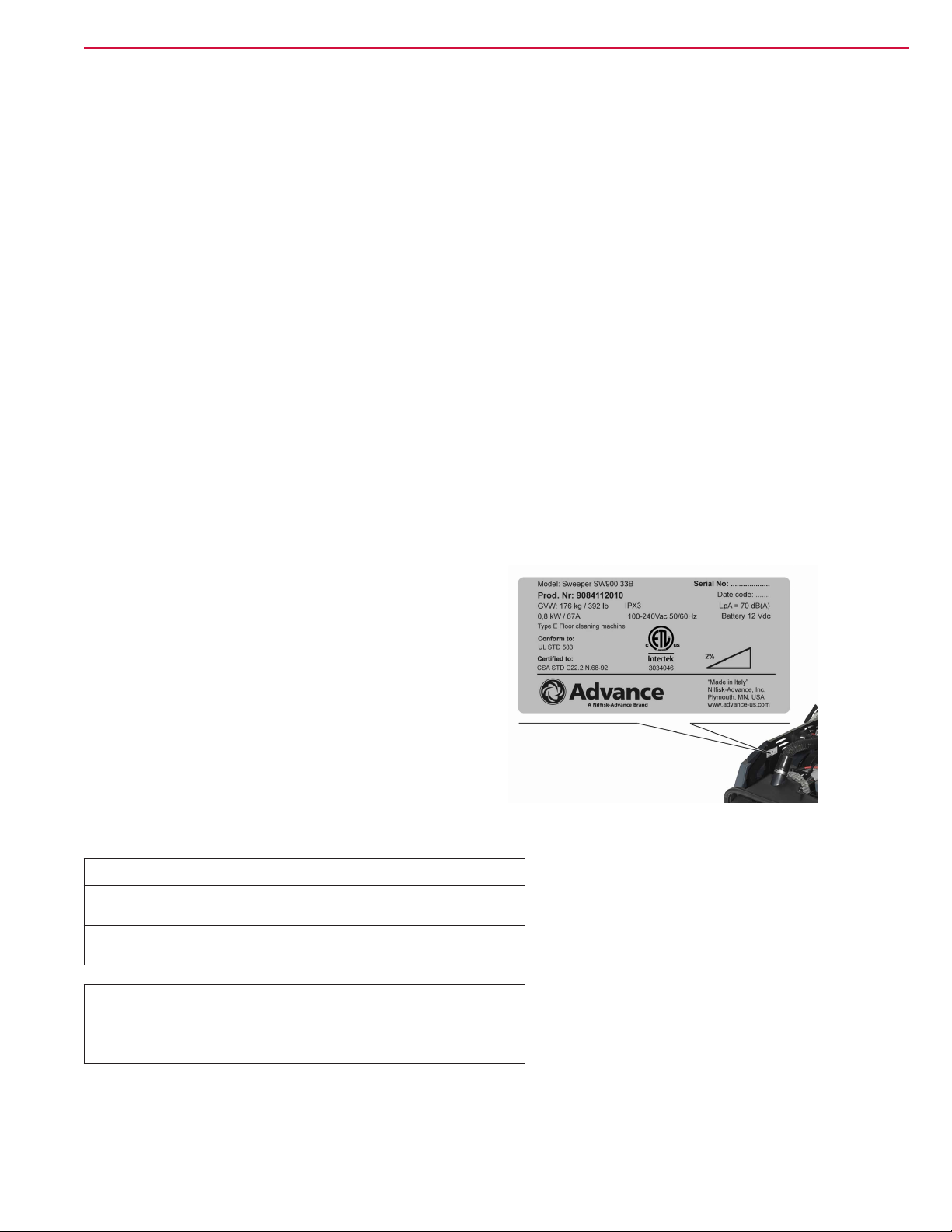
Serial Number Label
The machine serial number and model name are
marked on the plate (see the example to the side).
Product number and year of production are marked
on the same plate.
This information is useful when requiring machine
spare parts.
Use the following table to write down the machine
identication data.
MACHINE model .............................................................................................
PRODUCT code ..............................................................................................
MACHINE serial number .................................................................................
P200249
ENGINE model ................................................................................................
ENGINE serial number ....................................................................................
Page 7
Service Manual – SW900
General Information
Safety
The following symbols indicate potentially dangerous situations. Always read this information carefully and
take all necessary precautions to safeguard people and property.
Visible Symbols on the Machine
WARNING!
Carefully read all the instructions before
performing any operation on the machine.
WARNING!
Hot parts, danger of burns.
7
X %
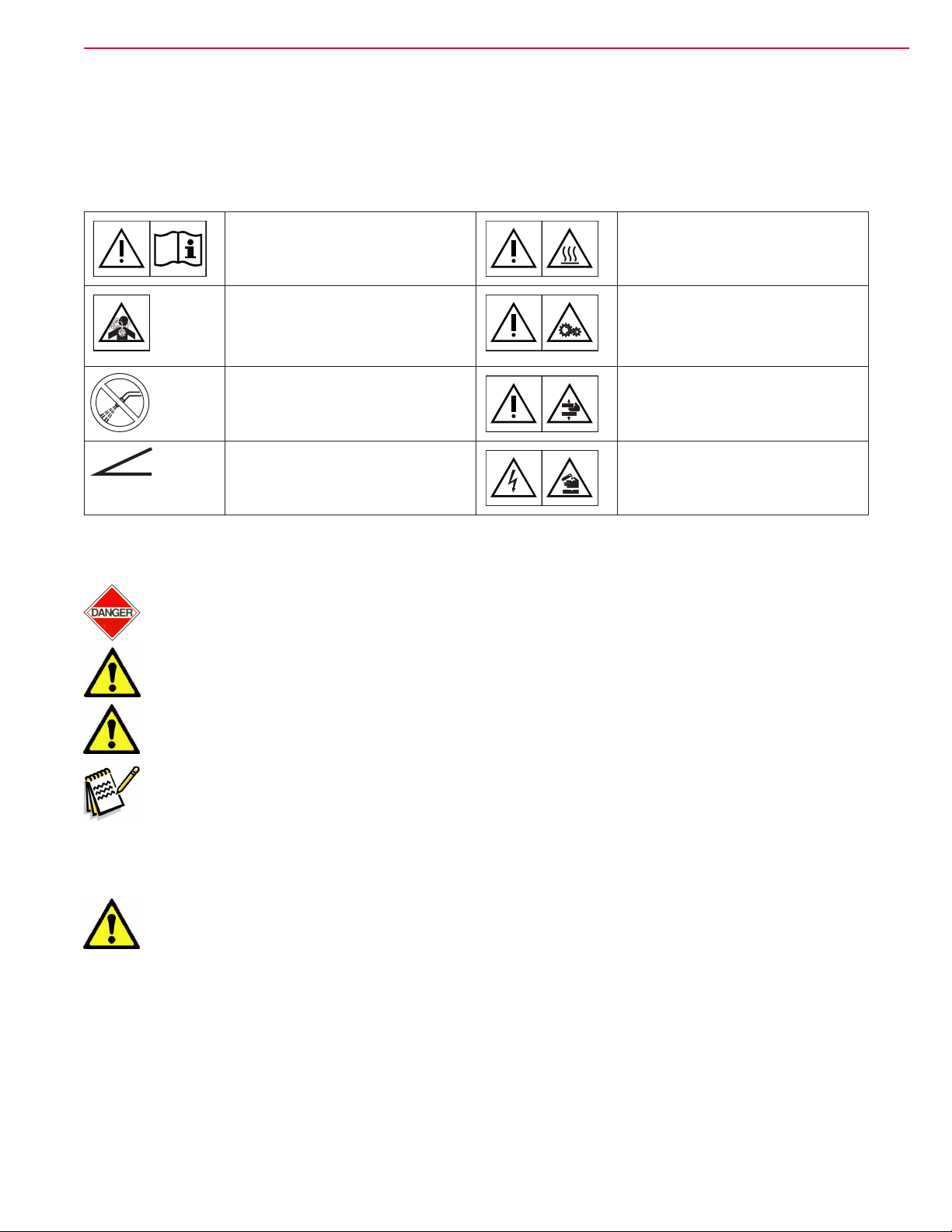
Symbols
Danger! It indicates a dangerous situation with risk of death for the operator.
Warning! It indicates a potential risk of injury for people or damage to objects.
Caution! It indicates a caution related to important or useful functions.
DANGER!
Internal combustion engine.
Do not inhale exhaust gas fumes.
Carbon monoxide (CO) can cause brain
damage or death.
WARNING!
Do not wash the machine with direct or
pressurized water jets.
WARNING!
Do not use the machine on slopes with a
gradient exceeding the specications.
WARNING!
Moving parts.
WARNING!
Moving parts. Danger of crushing.
WARNING!
Parts under voltage. Presence of corrosive
uids.
Note: It indicates a remark related to important or useful functions.
General Instructions
Specic warnings and cautions to inform about potential damages to people and machine are shown below.
Warning! Make sure to follow the safety precautions to avoid situations that may lead to
serious injuries.
(For SW900 B/Petrol)
– Before performing any maintenance, repair, cleaning or replacement procedure disconnect the
battery connector, remove the ignition key and engage the parking brake; for SW900 B also dis-
connect the batteries. Make sure that the machine cannot move independently.
– This machine must be used by properly trained operators only.
– Keep the batteries away from sparks, ames and incandescent material. Explosive gases are
released when charging the batteries.
Page 8

Service Manual – SW900
– Do not wear jewels when working near electrical components.
– Do not work under the lifted machine without supporting it with safety stands.
– When working under the open hood, ensure that it cannot be closed by accident.
– Do not operate the machine near toxic, dangerous, ammable and/or explosive powders, liquids
or vapors: This machine is not suitable for collecting dangerous powders.
(For SW900 P)
– Carbon monoxide (CO) can cause brain damage or death.
– The internal combustion engine of this machine can emit carbon monoxide.
– Do not inhale exhaust gas fumes.
– Only use indoors when adequate ventilation is provided, and with the help of an assistant.
– Be careful: fuel is highly ammable.
– Do not smoke or bring naked ames in the area where the machine is refuelled or where the fuel
is stored.
– Refuel outdoors or in a well-ventilated area, with the engine off.
– Turn off the engine and let it cool down for a few minutes, then remove the fuel tank plug.
– To allow the fuel to expand, do not ll the fuel tank beyond the upper limit mark (A) shown in
the gure.
General Information
8
P200250
– After refuelling, check that the fuel tank cap is rmly closed.
– If any fuel is spilled while refuelling, clean the tank area and allow the vapors to evaporate be-
fore starting the engine.
– Do not let fuel come into contact with the skin; do not breathe fuel vapors. Keep out of reach of
children.
– Do not tilt the engine or the machine too much to avoid fuel spillage.
– Do not lay any object on the engine.
– Stop the engine before performing any procedure on it. To avoid any accidental start, disconnect
the spark plug cap.
– See also the SAFETY RULES in the Engine Manual, which is to be considered an integral part of
this Manual.
(For SW900 B)
– If the machine is equipped with lead (WET) batteries, battery charging produces highly explosive
hydrogen gas. Charge the batteries in well-ventilated areas and away from naked ames.
– When lead batteries (WET) are installed, do not tilt the machine for more than 30° from the
horizontal plane to prevent the highly corrosive acid from leaking out of the batteries. When the
machine is to be tilted to perform maintenance procedures, remove the batteries.
Warning! Make sure to follow the safety precautions to avoid situations that may lead to
serious injuries, damages to materials or equipments.
Page 9

Service Manual – SW900
(For SW900 B/Petrol)
– Carefully read all the instructions before performing any maintenance/repair procedure.
– This machine is not intended for use by persons (including children) with reduced physical,
sensory or mental capabilities, or lack of experience and knowledge, unless they have been given
supervision or instruction concerning use of the machine by a person responsible for they safety.
Children should be supervised to ensure that they do not play with the machine.
– Close attention is necessary when used near children.
– Use only as shown in this Manual. Only Nilsk-Advance recommended accessories must be used.
– Check the machine carefully before each use, always check that all the components have been as-
sembled before use. If the machine is not perfectly assembled it can cause damages to people and
properties.
– Take all necessary precautions to prevent hair, jewels and loose clothes from being caught by the
machine moving parts.
– To avoid any unauthorized use of the machine, remove the ignition key.
– Do not leave the machine unattended without being sure that it cannot move independently.
– Do not use the machine on incline.
– Do not tilt the machine more than the angle indicated on the machine itself, in order to prevent
instability.
– Use only brooms supplied with the machine or those specied in the User Manual. Using other
brooms could reduce safety.
– Before using the machine, close all doors and/or covers as shown in the User Manual.
– Do not wash the machine with direct or pressurised water jets, or with corrosive substances.
– Use the machine only where a proper lighting is provided.
– While using this machine, take care not to cause damage to people or objects.
– Do not bump into shelves or scaffoldings, especially where there is a risk of falling objects.
– Do not lean liquid containers on the machine, use the relevant can holder.
– The storage temperature must be between 0°C and +40°C.
– The machine working temperature must be between 0°C and +40°C.
– The humidity must be between 30% and 95%.
– Always protect the machine against the rain and bad weather, both under operation and inactiv-
ity condition. Store the machine indoors, in a dry place. This machine must be used in dry conditions, it must not be used or kept outdoors in wet conditions.
– Do not use the machine as a means of transport, or for pushing/towing.
– Do not allow the brooms to operate while the machine is stationary to avoid damaging the oor.
– The machine maximum capacity is 30 kg (the maximum weight of waste).
– In case of re, use a powder re extinguisher, not a water one.
– This machine cannot be used on roads or public streets.
– Do not tamper with the machine safety guards.
– Follow the routine maintenance procedures scrupulously.
– Do not allow any object to enter into the openings. Do not use the machine if the openings are
clogged. Always keep the openings free from dust, hairs and any other foreign material which
could reduce the air ow.
– Do not remove or modify the plates afxed to the machine.
– In case of machine malfunctions, ensure that these are not due to lack of maintenance. If neces-
sary, request assistance from the authorised personnel or from an authorised Service Center.
– If parts must be replaced, require ORIGINAL spare parts from an Authorised Dealer or Retailer.
– To ensure machine proper and safe operation, the scheduled maintenance shown in the relevant
chapter of this Manual, must be performed by the authorised personnel or by an authorised Service Center.
– The machine must be disposed of properly, because of the presence of toxic-harmful materials
(batteries, oils, etc.), which are subject to standards that require disposal in special centres (see
the User Manual).
General Information
9
Page 10

Service Manual – SW900
(For SW900 P)
– While the engine is running, the silencer warms up; do not touch the silencer when it is hot to
avoid burns or res.
– Running the engine with an insufcient quantity of oil can seriously damage the engine. Check
the oil level with the engine off and the machine on a level surface.
– Never run the engine if the air lter is not installed, because the engine could be damaged.
– Technical service procedures on the engine must be performed by an authorised Dealer.
– Only use original spare parts or parts of matching quality for the engine. Using spare parts of
lower quality can seriously damage the engine.
– See also the SAFETY RULES in the Engine Manual, which is to be considered an integral part of
this Manual.
– Pay attention to hot parts when working near the engine and the mufer.
(For SW900 B)
– Before using the battery charger, ensure that frequency and voltage values, indicated on the
machine serial number plate, match the electrical mains voltage.
– Do not pull or carry the machine by the battery charger cable and never use the battery charger
cable as a handle. Do not close a door on the battery charger cable, or pull the battery charger
cable around sharp edges or corners. Do not run the machine on the battery charger cable.
– Keep the battery charger cable away from heated surfaces.
– Do not use the machine if the battery charger cable or plug is damaged. If the machine is not
working as it should, has been damaged, left outdoors or dropped into water, return it to the
Service Center.
– Before performing any maintenance procedure, disconnect the battery charger cable from the
electrical mains to avoid any risk of re, electric shock or injuries.
– Do not smoke while charging the batteries.
General Information
10
Page 11

Service Manual – SW900
Machine Lifting
Warning! Donotworkundertheliftedmachine,ifitisnotsecurelyxed.
Machine Transportation
Warning! Before transporting the machine, make sure that:
All covers are closed.
(For SW900 B) The battery connector is disconnected.
The machine is securely fastened to the means of transport.
General Information
11
Page 12
Service Manual – SW900
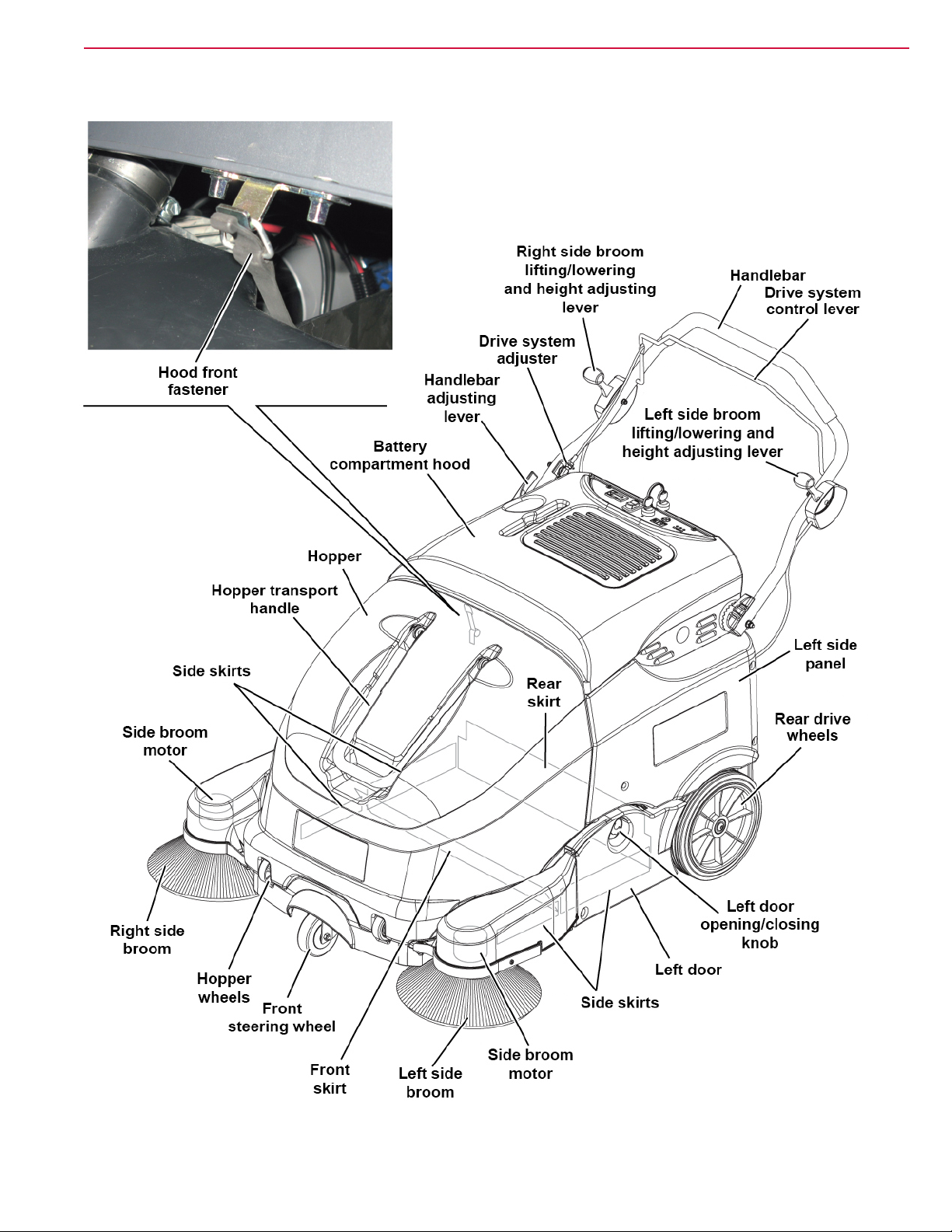
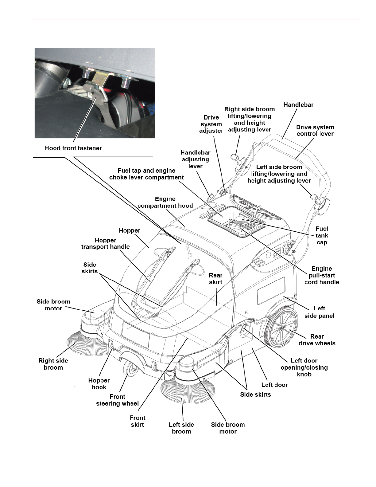
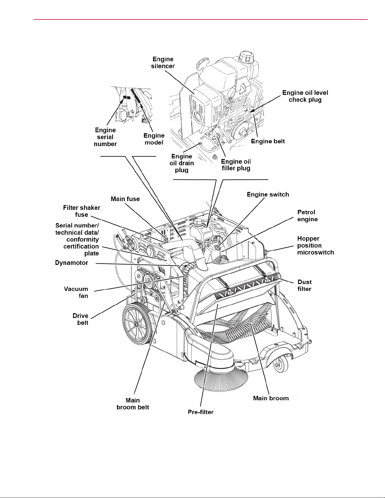
Machine Nomenclature (SW900 B) (know your machine)
General Information
12
P200251
Page 13
Service Manual – SW900
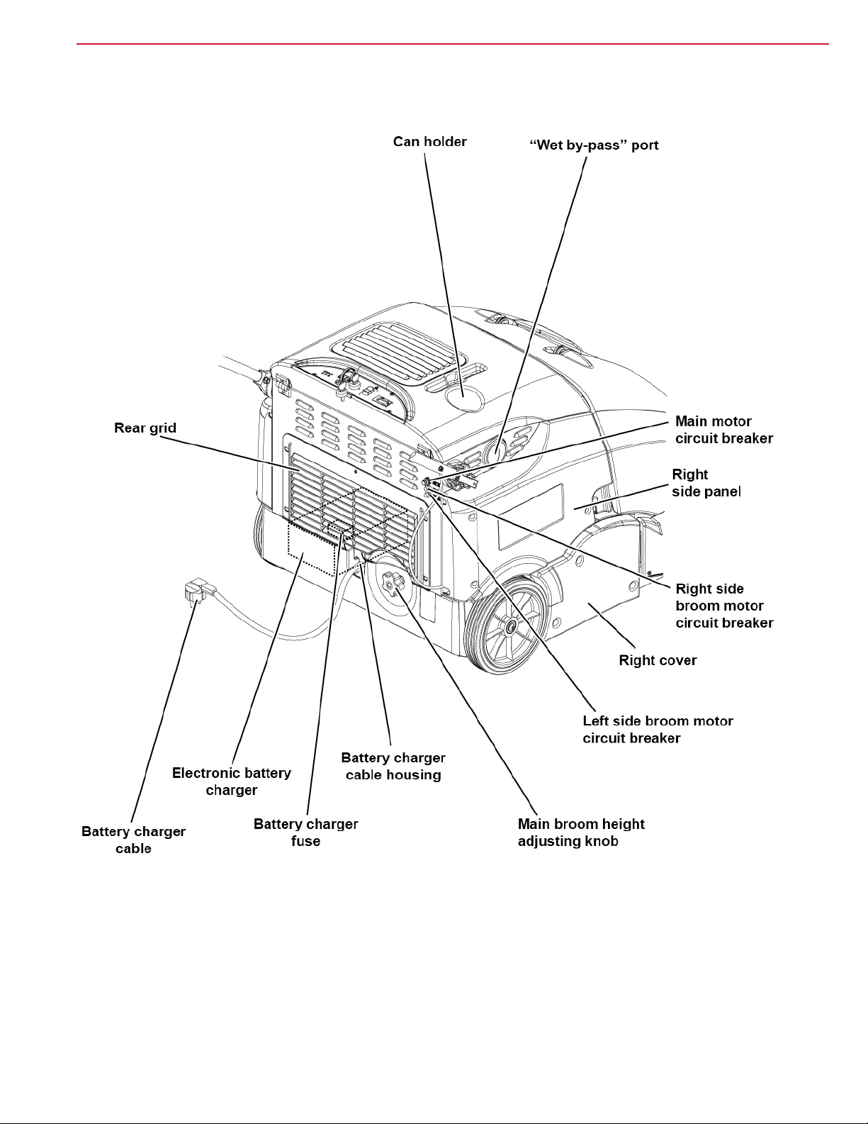
Machine Nomenclature (SW900 B) (Continues)
General Information
13
P200252
Page 14
Service Manual – SW900
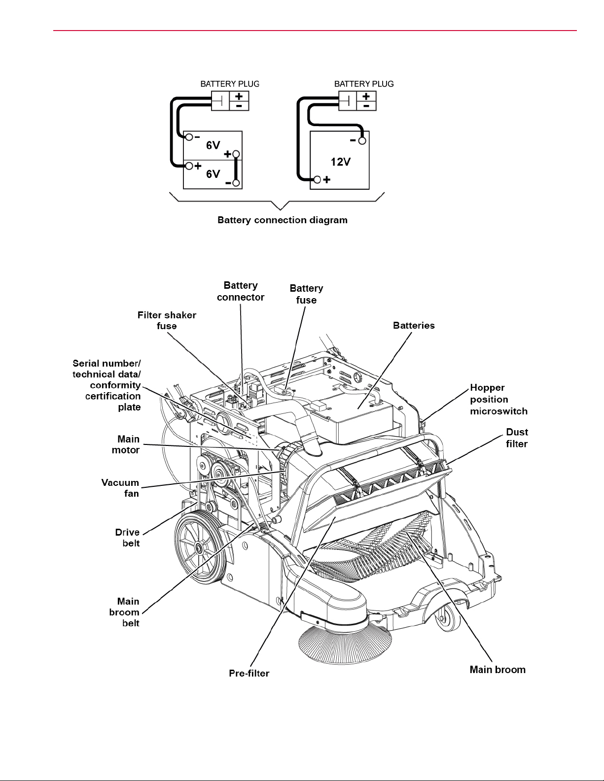
Machine Nomenclature (SW900 B) (Continues)
General Information
14
P200253
Page 15
Service Manual – SW900
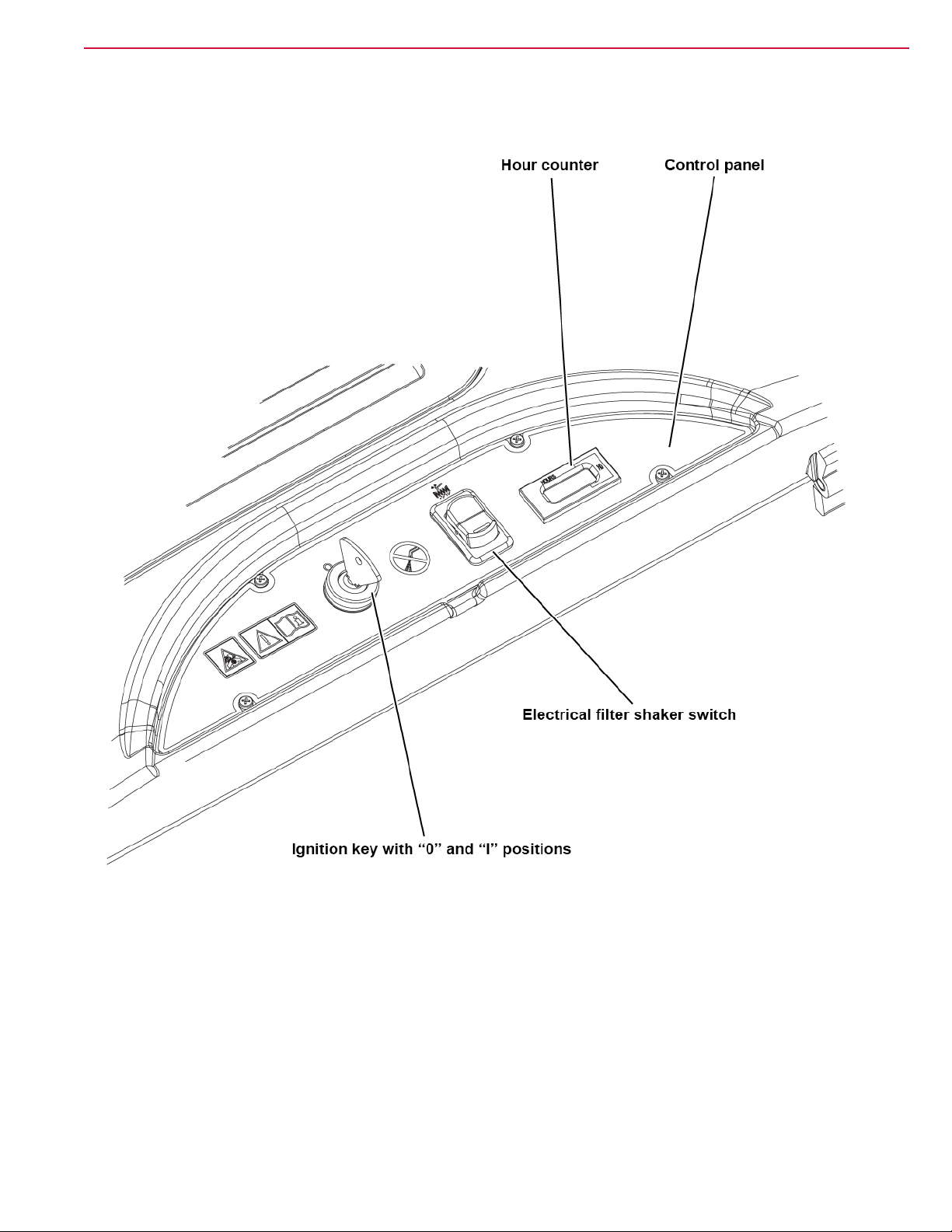
Machine Nomenclature (SW900 B) (Continues)
General Information
15
P200254
Page 16
Service Manual – SW900
Machine Nomenclature (SW900 P) (know your machine)
General Information
16
P200255
Page 17
Service Manual – SW900
Machine Nomenclature (SW900 P) (Continues)
General Information
17
P200256
Page 18

Service Manual – SW900
Machine Nomenclature (SW900 P) (Continues)
General Information
18
P200257
Page 19
Service Manual – SW900
Machine Nomenclature (SW900 P) (Continues)
General Information
19
P200258
Page 20

Service Manual – SW900
General Information
Service and Diagnostic Equipment
Besides a complete set of standard meters, the following instruments are necessary to perform fast checks and
repairs on Nilsk-Advance machines:
• Digital Volt Meter (DVM)
• Amp clamp with possibility of making DC measurements
• Battery charge tester to check 12V batteries
• Static control wrist strap
• Dynamometric wrench set
• A copy of the User Manual and Spare Parts List of the machine to be serviced (provided with the machine
or available at www.advance-us.com or other Nilsk-Advance websites).
The following equipment is also available at Nilsk-Advance Centers.
20
Page 21

Service Manual – SW900
Technical Data
General Information
21
Model
Cleaning width
Main broom size (length x diameter) 23.6 x 10.4 in (600 x 265 mm)
Side broom diameter 12.4 in (315 mm)
Theoretical working capacity
Hopper
Filter
Power 12V batteries -
Power - 2.1 kW @ 3,600 rpm
Engine model - Honda GX-100
Fuel tank capacity 0.77 liters
with one side broom 32.5 in (825 mm)
with two side brooms 41.3 in (1,050 mm)
with one side broom 39.987 ft2/h (3.715 m2/h)
with two side brooms 50.859 ft2/h (4.725 m2/h)
capacity 2.1 ft3 (60 Liters)
maximum transportable weight 66 lb (30 kg)
cleaning system
area 20.5 ft2 (1.9 m2)
ltering capacity 5-10 µm
Advance / Nilsk
SW900 B
Electrical lter shaker
(manual on Advance version)
Nilsk
SW900 P
Main motor
Dynamotor
Main broom speed 420 rpm
Side broom
Drive forward speed 2.8 mi/h (4.5 km/h)
Maximum gradient when working 2 %
Filter shaker motor 12 W
Total absorbed power 67A (0.8 kW) -
Working autonomy 3 h 1.5 h
Dimensions
(length x width x height)
power (drive/main broom/vacuum
system)
power (drive/main broom/vacuum
system)
motor power 0.05 hp (40 W)
speed 100 rpm
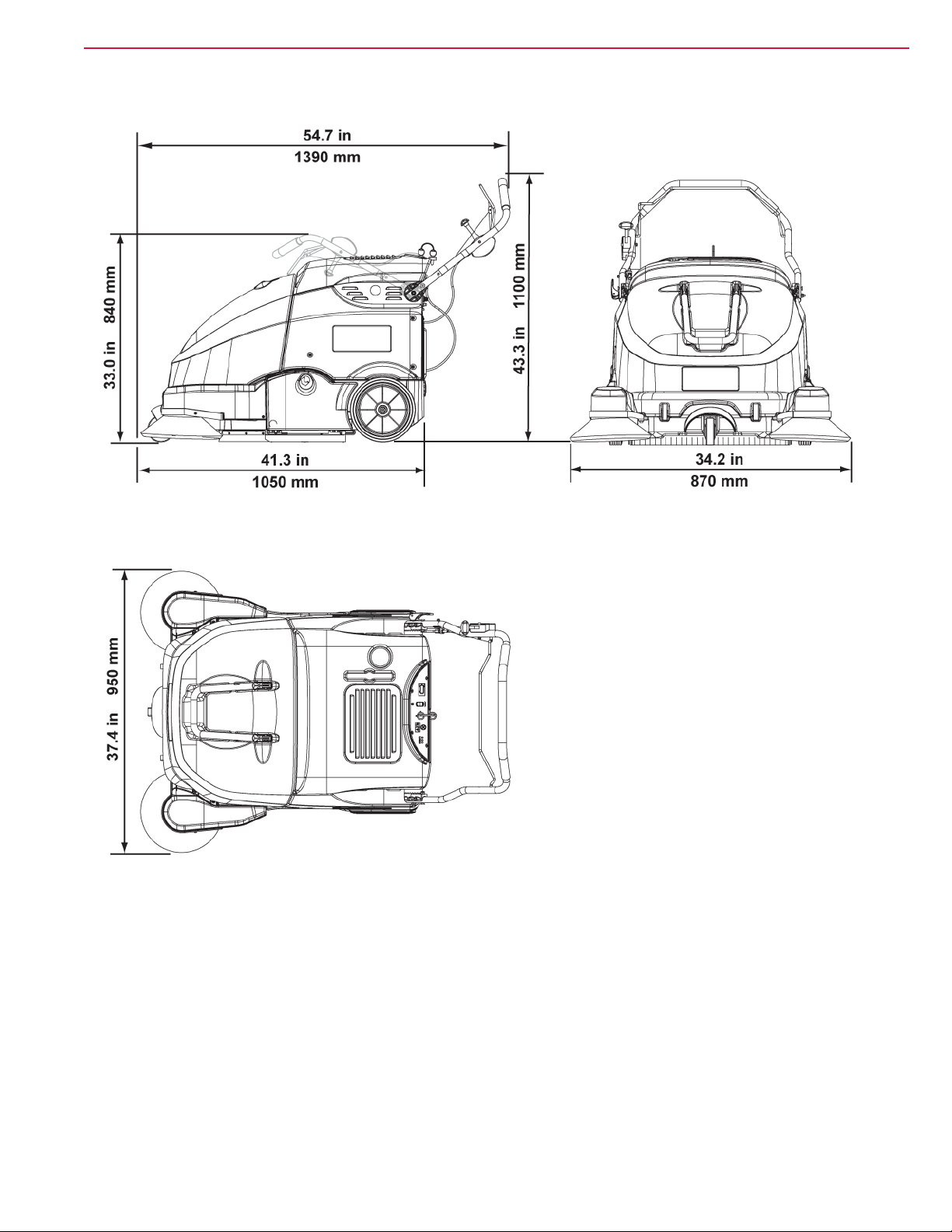
machine running 54.7 x 34.2 x 43.3 in (1,390 x 870 x 1,100 mm)
machine with folded handlebar 41.3 x 34.2 x 33 in (1,050 x 870 x 840 mm)
machine with two side brooms 54.7 x 37.4 x 43.3 in (1,390 x 950 x 1,100 mm)
battery compartment 12.9 x 9 x 15 in (327 x 230 x 380 mm)
0.9 hp (680 W) -
- 0.26 hp (198 W)
Page 22

Service Manual – SW900
Technical Data (Continues)
General Information
22
Model
kerb weight without batteries 181 lb (82 Kg) 194 lb (88 Kg)
Weight
Wheel specic pressure on the oor (front - rear wheels, in running
conditions)
Sound pressure level at workstation
(ISO 11201, ISO 4871, EN 60335-2-72) (LpA)
Machine sound pressure level
(ISO 3744, ISO 4871, EN 60335-2-72) (LwA)
IP protection class X3
U-turn space 61 in (1,550 mm)
Vibration level at the operator’s arms (ISO 5349-1) (**) < 98 in/s2 (< 2.5 m/s2) 157 in/s2 (4 m/s2)
total kerb weight 315 lb (143 Kg) 195 lb (88.5 Kg)
gross vehicle weight (GVW) 388 lb (176 Kg) 269 lb (122 Kg)
Advance / Nilsk
SW900 B
301 - 72 psi (2.1 - 0.5 N/mm2)
70 ± 3 dB(A) 78 ± 3 dB(A)
84 dB(A) 93 dB(A)
Nilsk
SW900 P
(*) Machines have been tested under the following conditions:
• Battery maximum size
• Brooms of maximum size
• Full hopper
• Optional components installed
• Weight on wheels checked
• Print on the oor checked on cement for each single wheel
Result expressed as maximum value for both front and rear wheels
(**) Under normal working conditions, on a level asphalt surface.
Machine Material Composition and Recyclability
Type Recyclable percentage SW900 B weight percentage SW900 P weight percentage
Aluminium 100 % 2.4 % 2.2 %
Electric motors - various 29 % 11.8 % 18.8 %
Ferrous materials 100 % 39.4 % 35.5 %
Wiring harnesses 80 % 1.8 % 1.6 %
Liquids 100 % 0.0 % 1.1 %
Plastic - non-recyclable material 0 % 9.4 % 8.6 %
Plastic - recyclable material 100 % 27.1 % 24.7 %
Polyethylene 92 % 5.9 % 5.4 %
Rubber 20 % 2.4 % 2.2 %
Page 23
Service Manual – SW900
Dimensions
General Information
23
P200259
Page 24

Service Manual – SW900
General Information
Maintenance
The lifespan of the machine and its maximum operating safety are ensured by correct and regular maintenance.
Warning! Read carefully the instructions in the Safety chapter before performing any
maintenance procedure.
The following tables provides the scheduled maintenance. The intervals shown may vary according to particu-
lar working conditions, which are to be dened by the person in charge of the maintenance.
For instructions on maintenance procedures, see the following paragraphs.
Scheduled Maintenance Table (SW900 B)
24
Procedure
Battery charging
Battery (WET) uid level check
Battery charger cable check
Dust lter cleaning and integrity check (2)
Side and main broom height check and adjustment
Skirt height and operation check
Dust lter holder gasket check
Electrical lter shaker operation check
Drive belt check/adjustment: drive system, main
broom.
Hopper position microswitch operation check
Drive belt replacement: drive system, main broom.
Main motor carbon brush check and replacement
(1) Daily or after using the machine.
(2) Or before use.
Upon
delivery
(1)
Every 10
hours
Every 50
hours
Every 200
hours
Every 400
hours
Page 25

Service Manual – SW900
Scheduled Maintenance Table (SW900 P)
General Information
25
Procedure
Engine oil level check (1) (5)
Engine air lter check (1) (5)
Dust lter cleaning and integrity check (1)
Side and main broom height check and
adjustment
Skirt height and operation check
Electrical lter shaker operation check
Engine air lter cleaning (3) (5)
Drive belt tensioner adjustment (1)
Drive belt check/adjustment: engine, drive system,
main broom
Engine Oil Change (2) (5) (6)
Spark plug check/cleaning (5)
Fuel tank and lter cleaning (4) (5)
Engine speed check
Dust lter holder gasket check
Engine air lter replacement (3) (5)
Upon
delivery
Every 10
hours
Every 50
hours
Every 100
hours
Every 200
hours
Every 300
hours
Spark plug replacement (2) (5)
Valve clearance check/adjustment (4) (5)
Hopper gasket integrity check
Hopper position microswitch operation check
Drive belt replacement: engine, drive system,
main broom
Dynamotor carbon brush check and replacement
Engine combustion chamber cleaning (4) (5)
Fuel hose check (4) (5) Every two years
(1) Or before use.
(2) Or every year.
(3) Or more often in dusty areas.
(4) Maintenance procedures to be performed by an authorised Honda Dealer, unless the operator has the service equipment
and data, and is qualied to perform such procedures.
(5) For the relevant procedure, see the Petrol Engine Manual.
(6) The rst time after 20 hours or after one month.
Page 26
Service Manual – SW900
Frame System
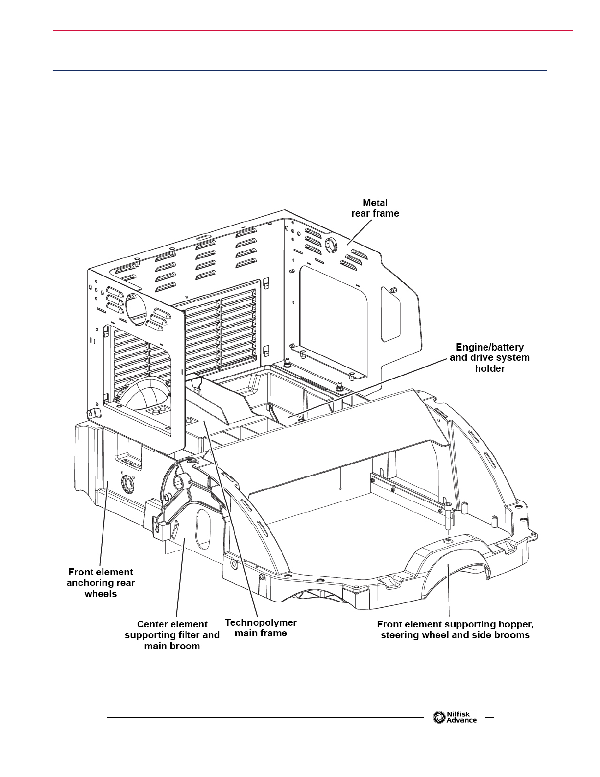
Frame (main parts)
• Technopolymer main frame
• Front element anchoring rear wheels
• Rear metal frame
• Engine/battery and drive system holder
Frame System
• Center element supporting lter and main broom
• Front element supporting hopper, steering wheel
and side brooms
26
P200260
Page 27
Dust Control System
Functional Description
The dust generated in the compartment of the main
broom is drawn toward the lter from a air ow generated by the fan on main motor (Battery version) or
dynamotor (Petrol version).
The lter located between the vacuum system and the
hopper, retain dirt which is then discharged into the
hopper itself.
The operation of the system depends on the activation
of the machine and the main broom.
The vacuum system consists of a fan installed on the
main motor / dynamotor which is powered by the relay (K0) (see Electrical and Control System chapter).
Dust Control System 27Service Manual – SW900
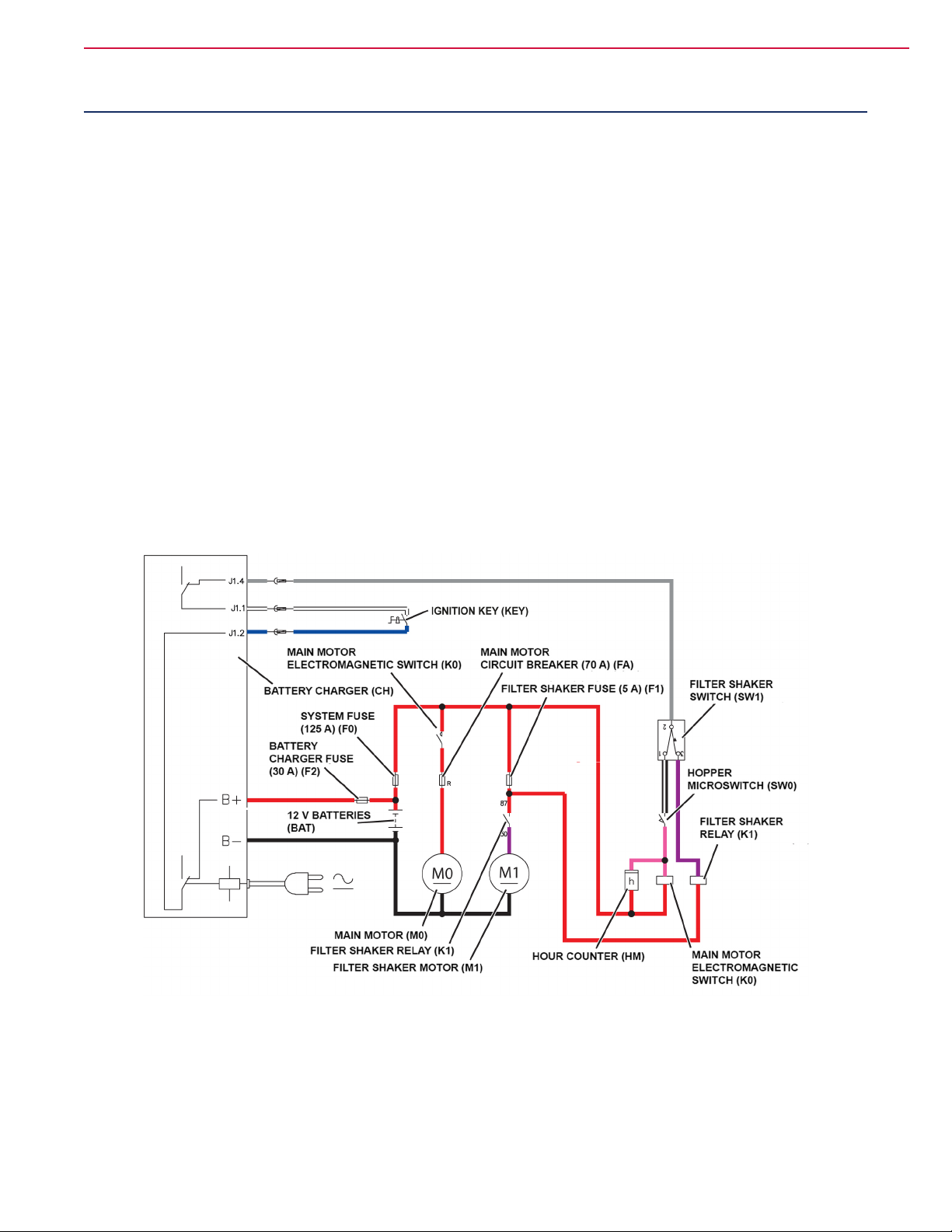
VERSION WITH ELECTRICAL FILTER SHAKER
The electric lter shaker system consists of a motor
(M1) which is powered by the relay (K1) and protected
by the fuse (F1) (see Electrical and Control System
chapter).
VERSION WITH MANUAL FILTER SHAKER
By operating on the lever on the right side of the machine, a rake acts mechanically on the lter ns allowing dirt trapped in the folds of the same to fall by
gravity into the hopper.
WiringDiagram(SW900Bwithelectricltershaker)
P200261
Page 28
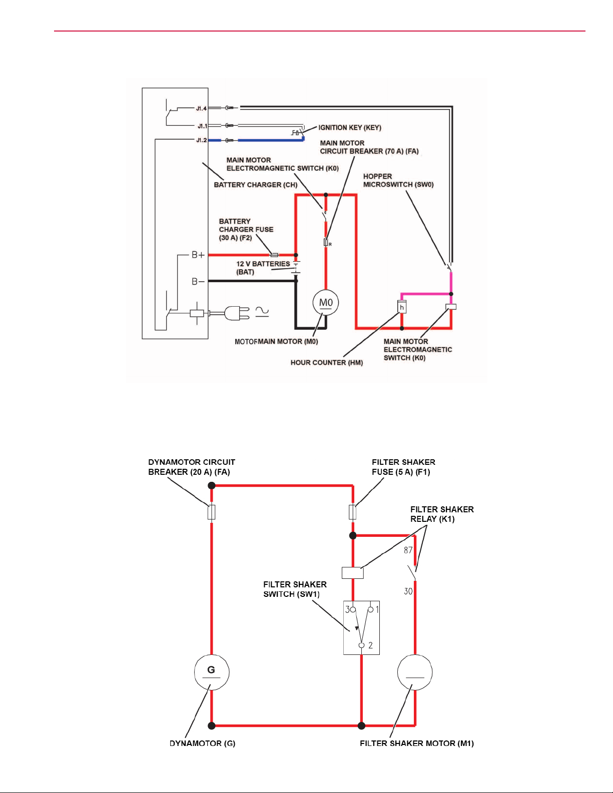
WiringDiagram(SW900Bwithmanualltershaker)
Dust Control System 28Service Manual – SW900
Wiring Diagram (SW900 P)
P200261
P200262
Page 29
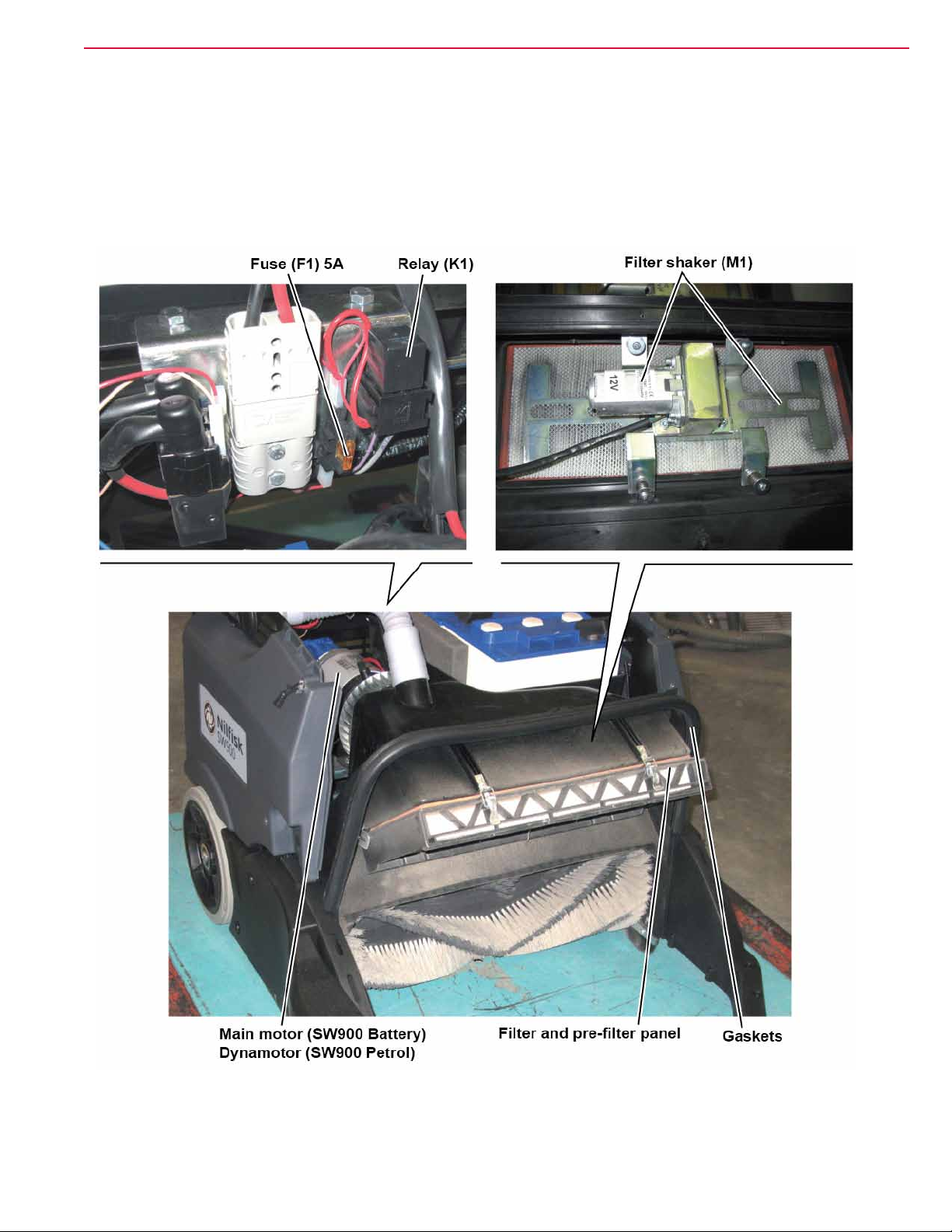
Component Locations
Dust Control System 29Service Manual – SW900
• Main motor (SW900 B)
• Dynamotor (SW900 P)
• Filter and pre-lter panel
• Gaskets
• Filter shaker (M1)
• Fuse (F1) 5A
• Relay (K1)
P200264
Page 30
Maintenance and Adjustments
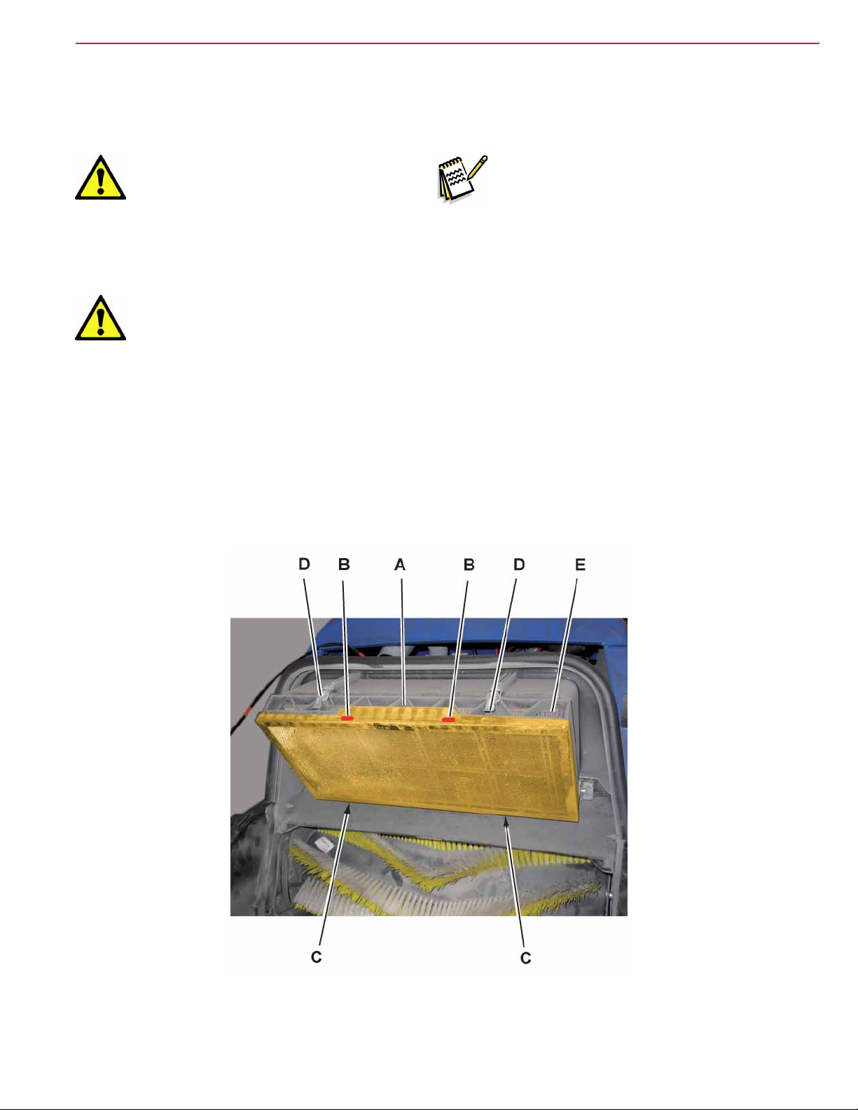
Paneldustlter,cleaningandintegritycheck/replacement
Dust Control System 30Service Manual – SW900
Caution! Thedustltermustbe
regularly cleaned to
maintaintheefciencyofthe
vacuum system. Follow the
recommendedlterservice
intervalsforthelongestlter
life.
Warning! Tocleanthelter,alwayswear
safety guards (such as safety
glasses, dust mask, gloves,
etc.)andcleanthelterina
well-ventilated area. Take care
nottopiercethelter.
Note: Besides the standard polyester
lter, paper lters are also
available.
1. Drive the machine on a level oor and ensure
that it cannot move.
2. Turn the ignition key to “0”.
3. Remove the hopper by using its transport handle
and wheels.
4. If equipped, remove the pre-lter (A) after
releasing the upper fasteners (B) and then the
lower fasteners (C).
5. Disengage the lever fasteners (D) and turn down
the lter holder assembly (E) to the end-of-
stroke (F).
P200265
Page 31

Paneldustlter,cleaningandintegritycheck/replacement(Continues)
Dust Control System 31Service Manual – SW900
6. Remove the dust lter (G).
7. In an outdoor area, clean the dust lter by
shaking it on a level and clean surface, tapping
the side (H), opposite to the wire gauze (I).
8. Complete the cleaning with compressed air (J)
(maximum pressure 6 bar) blowing only from the
side of the wire gauze (I) and in perpendicular
position as to the gauze itself.
According to the type of lter, observe the
following cautions:
• Polyester lter (standard): For a better clean-
ing, it is allowed to wash the lter with water
and non-lathering detergents. This provides
better quality cleaning but reduces the life of
the lter, which will have to be replaced more
frequently. The use of inadequate detergents
can damage the lter.
• Paper lter (optional): Do not use water or
detergents to clean it; the lter can be dam-
aged.
9. Check the lter body for tears.
10. Clean the gasket (K) along its perimeter and
check it for integrity. If necessary, replace the
lter.
11. Clean the gasket (L) along its perimeter and
check it for integrity; if necessary replace it.
12. If equipped, clean also the pre-lter with
compressed air (maximum pressure 6 bar)
13. Assemble the components in the reverse order of
disassembly.
P200266
Page 32

Troubleshooting
Trouble Possible causes Remedy
Dust Control System 32Service Manual – SW900
Dust/debris vacuuming is insufcient.
No vacuuming.
The electrical lter shaker does not work.
Dust/debris vacuuming is insufcient.
The lter is clogged.
The vacuum system compartment gasket is
damaged
The hopper is full. Empty the hopper.
The main motor circuit breaker (FA) is open.
The fuse (F2) is open. Replace the fuse.
The relay (K1) is broken. Replace.
The switch (SW1) is not efcient. Replace.
The lter shaker is broken. Repair/replace.
The lter is clogged.
The vacuum system compartment gasket is
damaged
Clean the dust lter by using the lter shaker
or by disassembling it.
Repair/replace
Wait for the main motor to cool down, then
reset the fuse by pressing the relevant pushbutton.
Clean the dust lter by using the lter shaker
or by disassembling it.
Repair/replace
Page 33

Removal and Installation
Electricalltershakermotoramperagecheck
Dust Control System 33Service Manual – SW900
Warning! This procedure must be
performedbyqualied
personnel only.
1. Drive the machine on a level oor and ensure
that it cannot move.
2. Turn the ignition key to “0”.
3. Remove the hopper by using its transport handle
and wheels.
4. Disengage the front fastener and open the
battery/engine hood.
5. Apply the amp clamps (A) on one cable (B) of the
lter shaker motor connection wiring harness.
6. Carefully operate and keep operated, the
hopper position microswitch (C) (to simulate the
presence of the hopper).
7. (For SW900 B) Turn the ignition key to “I”.
(For SW900 P) Turn the ignition key to “I” and
start the petrol engine.
8. Carefully activate the electrical lter shaker
switch (D) and check that the electrical lter
shaker motor amperage is between 3 and 4A at
12V.
9. Release the electrical lter shaker switch (D).
10. Turn the ignition key to “0”.
11. Remove the amp clamps (A).
P200267
Page 34

Electricalltershakermotoramperagecheck(Continues)
Dust Control System 34Service Manual – SW900
12. If the amperage is higher, perform the following
procedures to detect and correct it:
• Check that the relevant fuse (F1) 5A is prop-
erly positioned.
• Remove the electric lter shaker motor (see
the procedure in the next paragraph), and
check the condition of all its components.
Before removing the lter shaker motor (E),
check that the lter shaker frame (F) can
slide on the spacer bushes of the springs (G),
overcoming the resistance of the springs and
that it is not locked.
• If the above-mentioned procedures do not
produce the correct readings for the electrical
lter shaker motor amperage, the motor must
be replaced (see the procedure in the relevant
paragraph).
13. Close the battery/engine compartment hood and
engage the front fastener.
14. Reinstall the hopper.
15. Turn the ignition key to “0”.
P200268
Page 35

Electrical Filter Shaker Motor Disassembly/Assembly
Disassembly
Dust Control System 35Service Manual – SW900
1. Drive the machine on a level oor and ensure
that it cannot move.
2. Turn the ignition key to “0”.
3. Remove the hopper by using its transport handle
and wheels.
4. Disengage the front fastener and open the
battery/engine hood.
5. (For SW900 B) Remove the batteries and their
container (see the procedure in the relevant
paragraph).
6. Disconnect the “wet by-pass” hoses (A) from the
deector (B).
7. Remove all the mounting screws (C) of the
deector (B).
8. Move aside the conveyor (B).
P200269
Page 36

Electrical Filter Shaker Motor Disassembly/Assembly (Continues)
Dust Control System 36Service Manual – SW900
9. Disconnect the lter shaker connector (N).
10. For disassembling the lter shaker motor (E)
only, remove the four screws (F), then remove
it from its housing by disengaging the inner
eccentric (F).
The eccentric (F) must be rmly locked on the
shaft of the lter shaker motor.
For the complete removal of the motor (E), it is
necessary to disconnect the semiconnector out of
its wiring harness (L).
11. For disassembling the motor (E) with the holder
(O), remove the four screws (P).
12. For disassembly of the motor (E) with its of
the frame (G) electrical lter shaker, remove
the screws (H) and recover the springs (I), the
washers (J) and the spacer bushes (K).
Check the integrity of the disassembled parts.
Assembly
13. Assemble the components in the reverse order of
disassembly, and note the following:
- When reinstalling of the spacer bushes (K)
make sure that the same should are ushed
with the machine frame and that the slots
(M) of the frame (G) slide on spacers (K).
After assembling of the frame (G), check that
the frame can slide on the spacer bushes (K)
of the springs (I), overcoming the resistance
of the springs.
P200270
Page 37

Specications
Dust Control System 37Service Manual – SW900
Model
cleaning system
Filter
Filter shaker motor 12 W
Paper lter ltering capacity 99% @ 0.8 µm
Air ow 11301 ft3/h (320 m3/h)
Broom compartment vacuum - new lter 0.13 inH2O (3.6 mmH2O)
area 20.5 ft2 (1.9 m2)
ltering capacity 5-10 µm
Advance / Nilsk
SW900 B
Electrical lter shaker
(manual on Advance version)
Nilsk
SW900 P
Page 38

Electrical and Control System
Functional Description (SW900 B)
Electrical and Control System 38Service Manual – SW900
The machine functionality check is mainly performed
by the battery charger (CH) that monitors the battery
voltage (BAT) (also) during machine operation (not
only during recharging).
The ignition key (KEY) provides to the battery charger information about the machine on and off condition.
When the ignition switch (KEY) is closed, the battery
charger checks the battery voltage and, if it is insufcient, it activates the electromagnetic switch (K0).
The activation of the electromagnetic switch (K0) is
cut off when the battery charger is connected to the
electrical mains.
On the same circuit of the electromagnetic switch(K0),
there is the hopper safety switch (SW0) which prevents the activation of the electromagnetic switch
(K0) if the hopper is not properly positioned, or if the
upper hood is open.
For the versions equipped with electrical lter shaker, on the same circuit of the electromagnetic switch
(K0) there is the lter shaker switch (SW1). When
pressed, it turns off the electromagnetic switch (K0)
and activates the relay (K1).
The electromagnetic switch (K0) directly drives the
main motor (M0) and the side broom motors (M2) and
(M3*), while the relay (K1) (if equipped) turns on the
lter shaker motor (M1).
On the circuit of the side broom motors (M2) and
(M3*) there are microswitches (SW2) and (SW3*)
respectively, which deactivate the relevant motors
when the brooms are lifted from the ground by means
of the manual levers on the handlebar.
The display on the control panel shows the battery
charge status and the battery charger by means of
the LED electronic board (EB1), which is directly connected to the battery charger.
The hour counter (HM) is connected in parallel to the
electromagnetic switch (K0) and it counts the operating time of the main motor (M0).
The machine system is connected to the battery with
the connector (C1). The battery charger is always connected to the batteries.
* : when the left broom is equipped
Electrical Protections
The main motor (M0) is protected by the 70A circuit
breaker (FA).
The side broom motors (M2) and (M3*) are protected
by 5A circuit breakers (FB) and (FC*) respectively.
The lter shaker motor circuit (M1) is protected by
the 5A fuse (F1).
The battery charger (CH) is protected by the 30A fuse
(F2).
The main battery wiring harness is protected by a
125A safety fuse (F0) (on the supported versions).
Page 39

Functional Description (SW900 P)
Electrical and Control System 39Service Manual – SW900
The dynamotor (G) provides the current necessary
for the activation of the side broom motors (M2) and
(M3*), lter shaker circuit (M1) and hour counter
(HM).
The ignition key (KEY) turned to “0” inhibits the ac-
tivation of the engine, when turned to “1” it allows for
startup and operation.
When the engine is turned on, the current generated by the dynamotor (G) directly activates the side
broom motors (M2) and (M3*).
On the same circuit of the ignition switch (KEY), there
is the hopper safety switch (SW0) which prevents the
activation of the engine if the hopper is not properly
positioned, or if the upper hood is open.
On the versions equipped with electrical lter shaker,
the dynamotor (G) powers also the lter shaker switch
(SW1) which, when pressed, activates the relay (K1).
The relay (K1) turns on the lter shaker motor (M1).
On the circuit of the side broom motors (M2) and
(M3*) there are microswitches (SW2) and (SW3*)
respectively, which deactivate the relevant motors
when the brooms are lifted from the ground by means
of the manual levers on the handlebar.
The optional hour counter (HM) is connected to the
key circuit (KEY) and is powered by the dynamotor
(G) when the engine is running.
Electrical Protections
The dynamotor (G) is protected by the 20A fuse (FA).
The side broom motors (M2) and (M3*) are protected
by 5A circuit breakers (FB) and (FC*) respectively.
The lter shaker motor circuit (M1) is protected by
the 5A fuse (F1).
* : when the left broom is equipped
Page 40

Electrical and Control System 40Service Manual – SW900
Wiring Diagram
Fuses
SW900 B SW900 P
Acronym
F0 125A BATTERY (BATT) -
F1 5A FILTER SHAKER MOTOR (M1) 5A FILTER SHAKER MOTOR (M1)
F2 30A BATTERY CHARGER (CH) - -
FA 70A MAIN MOTOR (M0) 20A DYNAMOTOR (M0)
FB 5A RIGHT SIDE BROOM MOTOR (M2) 5A RIGHT SIDE BROOM MOTOR (M2)
FC 5A LEFT SIDE BROOM MOTOR (M3) 5A LEFT SIDE BROOM MOTOR (M3)
Relays / Electromagnetic Switches / Diodes
Nominal
Size
Protected Function Nominal Size Protected Function
Acronym
K0 MAIN MOTOR (M0) -
K1 FILTER SHAKER (M1) FILTER SHAKER (M1)
SW900 B SW900 P
Activated function Activated function
Page 41

WiringDiagram(SW900Bwithelectricltershaker)
LED ELECTRONIC BOARD (EB1)
Electrical and Control System 41Service Manual – SW900
LED ELECTRONIC BOARD (EB1)
IGNITION KEY (KEY)
MAIN MOTOR
ELECTROMAGNETIC SWITCH (K0)
BATTERY CHARGER (CH)
SYSTEM
FUSE (125 A) (F0)
BATTERY
CHARGER FUSE
(30 A) (F2)
12 V BATTERIES (BAT)
M0
RIGHT SIDE BROOM MICROSWITCH (SW2)
LEFT SIDE BROOM MICROSWITCH (SW3)
MAIN MOTOR (M0)
RIGHT SIDE BROOM MOTOR (M2)
LEFT SIDE BROOM MOTOR (M3)
FILTER SHAKER RELAY (K1)
FILTER SHAKER MOTOR (M1)
+ LDG
+ LDY
+ LDR
- COM
MAIN MOTOR CIRCUIT
BREAKER (70 A) (FA)
RIGHT SIDE BROOM
CIRCUIT BREAKER (5 A) (FB)
M3
M2
LEFT SIDE BROOM
CIRCUIT BREAKER (5 A) (FC)
FILTER SHAKER FUSE (5 A) (F1)
M1
HOUR COUNTER (HM)
FILTER SHAKER
SWITCH (SW1)
HOPPER
MICROSWITCH (SW0)
FILTER SHAKER
RELAY (K1)
MAIN MOTOR
ELECTROMAGNETIC
SWITCH (K0)
P200306
WiringDiagram(SW900Bwithmanualltershaker)
+ LDG
IGNITION KEY (KEY)
MAIN MOTOR
ELECTROMAGNETIC SWITCH (K0)
BATTERY CHARGER (CH)
BATTERY
CHARGER FUSE
(30 A) (F2)
12 V BATTERIES (BAT)
M0
RIGHT SIDE BROOM MICROSWITCH (SW2)
LEFT SIDE BROOM MICROSWITCH (SW3)
MAIN MOTOR (M0)
RIGHT SIDE BROOM MOTOR (M2)
LEFT SIDE BROOM MOTOR (M3)
+ LDY
+ LDR
- COM
MAIN MOTOR CIRCUIT
BREAKER (70 A) (FA)
RIGHT SIDE BROOM
CIRCUIT BREAKER (5 A) (FB)
M3
M2
LEFT SIDE BROOM
CIRCUIT BREAKER (5 A) (FC)
HOUR COUNTER (HM)
HOPPER
MICROSWITCH (SW0)
MAIN MOTOR
ELECTROMAGNETIC
SWITCH (K0)
P200306
Page 42

Wiring Diagram (SW900 P)
LEFT SIDE BROOM
CIRCUIT BREAKER (5 A) (FC)
RIGHT SIDE BROOM
CIRCUIT BREAKER (5 A) (FB)
FILTER SHAKER FUSE (5 A) (F1)
LEFT SIDE BROOM
MICROSWITCH (SW3)
FILTER SHAKER RELAY (K1)
Electrical and Control System 42Service Manual – SW900
DYNAMOTOR CIRCUIT
BREAKER (20 A) (FA)
IGNITION KEY (KEY)
HOPPER
MICROSWITCH (SW0)
ENGINE
SPARK PLUG (SPK)
G
RIGHT SIDE BROOM
MICROSWITCH (SW2)
LEFT SIDE BROOM
MOTOR (M3)
RIGHT SIDE BROOM
MOTOR (M2)
M3 M2
M1
FILTER SHAKER
SWITCH (SW1)
FILTER SHAKER MOTOR (M1)
DYNAMOTOR (G)
FRAME (FR)
HOUR COUNTER (HM)
P200307
Page 43

Component Locations (SW900 B)
Electrical and Control System 43Service Manual – SW900
• Dashboard
• Ignition key (KEY)
• Filter shaker (SW1)
• Hour counter (HM)
• LED electronic board (EB1)
P200308
Page 44

Component Locations (SW900 B) (Continues)
Electrical and Control System 44Service Manual – SW900
• Wiring harnesses
• Main motor (M0)
• Batteries (BAT)
• Battery connector
• Main motor relay (K0)
• 5A fuse, electrical lter shaker (F1)
• 125A fuse, battery (F0)
• Reduction unit
• Filter shaker relay (K1)
P200273
Page 45

Component Locations (SW900 B) (Continues)
• Battery charger (CH)
• Hopper position microswitch (SW0)
• 30A fuse, battery charge (F2)
• 70A circuit breaker, main motor (FA)
• 5A circuit breaker, right side broom motor (FB)
• 5A circuit breaker, left side broom motor (FC)
Electrical and Control System 45Service Manual – SW900
P200309
Page 46

Component Locations (SW900 P)
Electrical and Control System 46Service Manual – SW900
• Dashboard
• Ignition key (KEY)
• Filter shaker (SW1)
• Hour counter (HM)
P200310
Page 47

Component Locations (SW900 P) (Continues)
Electrical and Control System 47Service Manual – SW900
• Wiring harnesses
• Dynamotor (G)
• Filter shaker relay (K1)
• Electrical lter shaker (F1) fuse (5A)
• Dynamotor (FA) fuse (20A)
• Reduction unit
P200274
Page 48

Component Locations (SW900 P) (Continues)
• Hopper position microswitch (SW0)
• Right side broom motor (FB) circuit breaker (5A)
• Left side broom motor (FC) circuit breaker (5A)
Electrical and Control System 48Service Manual – SW900
P200311
Page 49

Maintenance and Adjustments
Charging the batteries (SW900 B)
Electrical and Control System 49Service Manual – SW900
Caution! Charge the batteries when
the yellow (A) or red (B) LED
turns on, or at the end of each
working cycle. Keeping the
batteries charged make their
life last longer.
Warning! When the batteries are
discharged, charge them as
soon as possible, as that
condition makes their life
shorter.
Warning! If the machine is equipped
with lead (WET) batteries,
battery charging produces
highlyexplosivehydrogen
gas. Charge the batteries in
well-ventilated areas and away
fromnakedames.
Do not smoke while charging
the batteries.
While charging the batteries
always keep the hood open.
Warning! Pay careful attention when
charging lead batteries (WET)
astheremaybebatteryuid
leakages.Thebatteryuid
is corrosive. If it comes in
contact with skin or eyes,
rinse thoroughly with water
and consult a physician.
1. Drive the machine on a level oor and ensure
that it cannot move.
2. Turn the ignition key to “0”.
P200275
Page 50

Charging the batteries (SW900 B) (Continues)
Electrical and Control System 50Service Manual – SW900
3. Remove from the housing (C) the electrical
cable (D) of the electronic battery charger, then
connect it to the electrical mains.
Warning! The mains voltage and
frequency must match the
electronic battery charger
values shown on the machine
serial number plate.
Note: When the electronic battery
charger is connected to the
electrical mains, all machine
functions are automatically
disabled.
4. When the green LED (E) turns on, the batteries
are charged.
For further information about the battery
charger operation, see the Battery Charger
Manual.
5. Disconnect the electronic battery charger
electrical cable (D) from the electrical mains,
then place it in the housing (C).
6. Now the machine is ready to be used.
P200276
Page 51

Fuse Check/Replacement/Reset (SW900 B)
Electrical and Control System 51Service Manual – SW900
1. Drive the machine on a level oor and ensure
that it cannot move.
2. Turn the ignition key to “0”.
Fuse Check/Reset
3. Check one of the following fuses for deactivation:
- (A): 70A fuse (FA), main motor
- (B): 5A fuse (FB), right side broom motor
- (C): 5A fuse (FC), left side broom motor
4. Reset any deactivated fuse, when the component
that caused deactivation has fully cooled down.
Various Fuse Check/Replacement
5. Remove the hopper by using its transport handle
and wheels.
6. Disengage the front fastener and open the
battery compartment hood.
7. Disconnect the battery connector.
8. Remove the rear grid after removing the upper
mounting screw and disengaging the fasteners.
9. Disengage and open the cover (I), then check the
fuse:
- (J): 30A fuse (F2), battery charger
- If necessary, remove the nuts (D) and replace
the fuse (J). Screw down and tighten the
nuts.
P200277
Page 52

Fuse Check/Replacement/Reset (SW900 B) (Continues)
Electrical and Control System 52Service Manual – SW900
10. Check/replace the fuse:
- (E): 5A lamellar fuse (F1), electrical lter
shaker
11. Check/replace the fuse:
- (F): 125A fuse (F0), battery
When reinstalling the fuse (F), engage its
ange (G) on the electrical cable terminals
(H), as shown in the gure.
Reassembly
12. Install the rear grid by engaging the fasteners
and then tighten the upper mounting screw.
13. Connect the battery connector.
14. Close the battery compartment hood and engage
the front fastener.
15. Install the hopper by using its transport handle
and wheels.
P200278
Page 53

Fuse Check/Replacement/Reset (SW900 P)
Electrical and Control System 53Service Manual – SW900
1. Drive the machine on a level oor and ensure
that it cannot move.
2. Turn the ignition key to “0”.
Fuse check/reset
3. Check one of the following fuses for deactivation:
- (A): 5A fuse (FB), right side broom motor
- (B): 5A fuse (FC), left side broom motor
4. Reset any deactivated fuse, when the component
that caused deactivation has fully cooled down.
Lamellar Fuse Check/Replacement
5. Remove the hopper by using its transport handle
and wheels.
6. Disengage the front fastener and open the
engine compartment hood.
7. On the right side of the engine (C), check/replace
the fuses:
- (D): 20A fuse (F0), main
- (E): 5A fuse (F1), electrical lter shaker
Reassembly
8. Close the engine compartment hood and engage
the front fastener.
9. Install the hopper by using its transport handle
and wheels.
P200279
Page 54

Troubleshooting (SW900 B)
Trouble Possible causes Remedy
The battery connector is disconnected Connect
The batteries are discharged Charge
Electrical and Control System 54Service Manual – SW900
The main motor does not start
The right/left broom motor does not run
The hopper is not in the correct position
The upper hood is open
The circuit breaker (FA) is open
The lever is not activated correctly
The circuit breaker (FB) or (FC) is open
Adjust
Check the operation of the microswitch
Close it properly
Check the operation of the microswitch
Press the push-button on the fuse, if the
trouble persists remove the overload cause
Use the lever up to the end-of-stroke
Check the operation of the microswitch
Press the push-button on the fuse, if the
trouble persists remove the overload cause
Page 55

Electrical and Control System 55Service Manual – SW900
Removal and Installation
Battery Installation and Battery Type Setting (WET or GEL) (SW900 B)
Warning! The electric components of
the machine can be seriously
damaged if the batteries are
either improperly installed
or connected. The batteries
mustbeinstalledbyqualied
personnel only.
According to the type of
batteries (WET or GEL-AGM),
set the machine battery
charger.
Check the batteries for
damage before installation.
Disconnect the battery
connector and the battery
charger plug.
Handle the batteries with great
care.
Install the battery terminal
protection caps supplied with
the machine.
Warning! Do not tilt the lead batteries
(WET) to prevent the highly
corrosive acid from leaking
out of the batteries. Do not
connect, not even accidentally,
the battery positive and
negative terminals by using
tools, keys, etc. This could
cause dangerous shortcircuits.
The machine requires one 12V battery, or two 6V batteries connected according to the diagram below.
The machine can be supplied in one of the following
congurations:
• WET or GEL batteries already installed on the
machine
• Without batteries
Note: The machine is supplied with
the battery charger set for using
generic GEL-AGM batteries.
P200312
Page 56

Electrical and Control System 56Service Manual – SW900
Battery Installation and Battery Type Setting (WET or GEL) (SW900 B) (Continues)
Battery Removal
1. Drive the machine on a level oor and ensure
that it cannot move.
2. Turn the ignition key to “0”.
3. Remove the hopper by using its transport handle
and wheels.
4. Disengage the front fastener and open the
battery compartment hood.
5. Disconnect the battery connector.
6. Disengage the guards (A) from the battery
terminals.
7. Disconnect the battery terminals.
8. Carefully remove the batteries (B).
Battery installation
1. Install on the machine the type of batteries
which is compatible with the setting of the
machine; for checking the setting of the machine
or to change it, refer to the procedure described
below.
2. Route and install the battery cables, then
carefully tighten the nut on each battery
terminal.
3. Engage the guards (A) on the battery terminals.
4. Connect the battery connector.
5. Close the battery compartment hood and engage
the front fastener.
6. Install the hopper on the machine, by using its
transport handle and wheels.
P200313
Page 57

Machine Check/Setting
Electrical and Control System 57Service Manual – SW900
1. Drive the machine on a level oor and ensure
that it cannot move.
2. Turn the ignition key to “0”.
3. Remove the hopper by using its transport handle
and wheels.
4. Disengage the front fastener and open the
battery compartment hood.
5. Disconnect the battery connector.
6. Check the battery cables for insulation.
7. Remove the battery charger cable (A) from the
housing; connect it temporarily to the electrical
mains and, during the connection, check the
number and color of the LED ashings (B),
then compare them with the indications in the
following table, to determine the battery setting
of the machine.
Type of battery set on
the machine
EXIDE™ Two ashes of the yellow LED
OPTIMA™
DISCOVER™
GEL/AGM (generic) Two ashes of the green LED
WET (all makes) Two ashes of the red LED
Two ashes of the green and yellow
LEDs together
Two ashes of the red and green LEDs
together
Flashes
8. If it is necessary to install batteries which are
different from the machine setting, it is possible
to change the machine settings according to the
following procedure.
9. If equipped, remove the batteries from the
machine and also remove the battery case.
P200314
Page 58

Machine Check/Setting (Continues)
Electrical and Control System 58Service Manual – SW900
10. In the battery compartment, lift the rubber mat
(C).
12. Carefully set the switches (E, F, G) as shown in
the following table to set machine according to
the type of batteries to be installed.
11. Lift the battery charger plate (D).
Type of battery set on the machine E switch F switch G switch
EXIDE™ OFF OFF OFF
OPTIMA™ OFF ON OFF
DISCOVER™ ON OFF OFF
GEL/AGM (generic) ON ON OFF
WET (all makes) Any Any ON
Set the switch (H) as shown below:
13. Repeat steps 6. and 7. to check that the machine
has been set correctly.
- For batteries having capacity of 150Ah
or higher (discharge in 5 hours) leave the
14. Reinstall the plate (D) and the oor mat (C).
default setting to OFF (nominal charge
current 25A).
- For batteries having capacity lower than
15. Install the battery case.
16. Install the batteries.
150Ah (discharge in 5 hours) set H switch to
ON (nominal charge current 15A).
P200315
Page 59

Main motor amperage check (SW900 B)
Electrical and Control System 59Service Manual – SW900
Warning! This procedure must be
performedbyqualied
personnel only.
1. Drive the machine on a level oor and ensure
that it cannot move.
2. Turn the ignition key to “0”.
3. Remove the hopper by using its transport handle
and wheels.
4. Check that the side brooms are lifted.
5. Disengage the front fastener and open the
battery compartment hood.
6. Remove the screws (A) and the right side panel
(B) from the machine.
7. Turn the tensioner (C) in the direction shown by
the arrow and disengage the belt (D) from the
pulley (E).
8. Turn the tensioner (F) in the direction shown by
the arrow and disengage the belt (G) from the
pulley (H).
9. Apply amp clamps on a cable (I) of the main
motor (J).
10. Carefully operate and keep operated, the
hopper position microswitch (K) (to simulate the
presence of the hopper).
11. Turn the ignition key to “I” thus turning on the
main motor; check that the amperage of the
motor (J) is between 30 and 35A at 24V.
12. Turn the ignition key to “0”.
13. Remove the amp clamp.
P200280
Page 60

Main motor amperage check (SW900 B) (Continues)
Electrical and Control System 60Service Manual – SW900
14. If the amperage is higher, perform the following
procedures to detect and correct it:
• Check that there are no obstacles to the
rotation of the pulleys (E) and (H) and the
reduction unit (L).
• Check the main motor carbon brushes (see
the procedure in the relevant paragraph).
• If necessary, disassemble the main motor
(see the procedure in the relevant para-
graph), and check the condition of all its
components.
If the above-mentioned procedures do not lead
to a correct amperage, the main motor must
be replaced (see the procedure in the relevant
paragraph).
Reassembly
15. Release the hopper position microswitch (K)
from the forced operation, and check that the
microswitch operates properly.
16. Turn the tensioner (F) in the direction shown by
the arrow and engage the belt (G) to the pulley
(H) and to the tensioner (F); check the proper
operation of the tensioner (F).
17. Turn the tensioner (C) in the direction shown by
the arrow and engage the belt (D) to the pulley
(E) and to the tensioner (C); check the proper
operation of the tensioner (C).
18. Perform steps 3. 5. and 6. in the reverse order.
P200281
Page 61

Dynamotor Voltage Check (SW900 P)
Electrical and Control System 61Service Manual – SW900
Warning! This procedure must be
performedbyqualied
personnel only.
1. Drive the machine on a level oor and ensure
that it cannot move.
2. Turn the ignition key to “0”.
3. Remove the hopper by using its transport handle
and wheels.
4. Carefully operate and keep operated, the hopper
position microswitch (to simulate the presence of
the hopper).
5. Check that the main and side brooms(s) are
lifted.
6. Turn the ignition key to “I” and start the petrol
engine (as shown in the User Manual); wait
at least 5 minutes that the engine reaches the
target speed.
7. Disengage the front fastener and open the
engine compartment hood.
8. Move aside the guards (A) of the terminals (B)
and (C) of the dynamotor (D).
9. Apply the detectors (E) and (F) of the tester
on the terminals (B) and (C) and measure the
voltage produced by the dynamotor, which must
be between the 12V and 14V.
Stop the petrol engine (as shown in the User
Manual).
Turn the ignition key to “0”.
P200282
Page 62

Dynamotor Voltage Check (SW900 P) (Continues)
Electrical and Control System 62Service Manual – SW900
If the voltage is lower than the specied value,
perform the following procedures to detect the
cause and correct it:
• Check that the drive belt between the
engine and reduction unit is properly tensioned (see the procedure in the relevant
paragraph) and that the pulleys are efcient
and not loose.
• Check that the reduction unit is correctly
closed.
• Check the dynamotor carbon brushes (see
the procedure in the relevant paragraph).
• If necessary, disassemble the dynamotor
(see the procedure in the relevant para-
graph), and check the condition of all its
components.
If the above-mentioned procedures do not lead
to a correct voltage, the dynamotor must be
replaced (see the procedure in the relevant
paragraph).
Reassembly
10. Close the engine compartment hood and engage
the front fastener.
11. Release the hopper position microswitch
from the forced operation, and check that the
microswitch operates properly.
12. Install the hopper by using its transport handle
and wheels.
Page 63

Main motor carbon brush replacement (SW900 B)
Disassembly
1. Drive the machine on a level oor and ensure
that it cannot move.
2. Turn the ignition key to “0”.
3. Remove the hopper by using its transport handle
and wheels.
4. Disengage the front fastener and open the
battery compartment hood.
5. Disconnect the battery connector.
6. Remove the batteries and their container (see
the procedure in the relevant paragraph).
7. Remove the screws (A) and the right side panel
(B) from the machine; then remove also the left
side panel.
Electrical and Control System 63Service Manual – SW900
8. On the main motor, release the fastener (C) and
remove the protection band (D) of the carbon
brushes.
9. Remove the fastening screws (E) of the electrical
connections of the four carbon brushes (F).
10. Remove the four carbon brushes (F) from
their housings, by disengaging them from the
retaining springs (G).
11. Check the two carbon brushes (F) for wear.
Replace the carbon brushes when: the contact
with the motor armature is insufcient, the
carbon brushes are worn, the carbon brush
contact surface is not integral, the thrust spring
is broken, etc. If the length of the carbon brushes
is insufcient, these must be replaced.
In this cases, replace all motor carbon brushes.
Assembly
12. Assemble the components in the reverse order of
disassembly.
P200316
Page 64

Dynamotor Carbon Brush Replacement (SW900 P)
Disassembly
1. Drive the machine on a level oor and ensure
that it cannot move.
2. Turn the ignition key to “0”.
3. Remove the hopper by using its transport handle
and wheels.
4. Disengage the front fastener and open the
engine compartment hood.
5. Remove the screws (A) and the right side panel
(B) from the machine; then remove also the left
side panel.
6. On the dynamotor, release the fastener (C) and
remove the protection band (D) of the carbon
brushes.
Electrical and Control System 64Service Manual – SW900
7. Remove the fastening screws (E) of the electrical
connections of the four carbon brushes (F).
8. Remove the four carbon brushes (F) from
their housings, by disengaging them from the
retaining springs (G).
9. Check the two carbon brushes (F) for wear.
Replace the carbon brushes when: the contact
with the dynamotor armature is insufcient,
the carbon brushes are worn, the carbon brush
contact surface is not integral, the thrust spring
is broken, etc. If the length of the carbon brushes
is insufcient, these must be replaced.
In this cases, replace all motor carbon brushes.
Assembly
10. Assemble the components in the reverse order of
disassembly.
P200316
Page 65

Main Motor or Fan Removal/Installation (SW900 B)
Disassembly
1. Drive the machine on a level oor and ensure
that it cannot move.
2. Turn the ignition key to “0”.
3. Remove the hopper by using its transport handle
and wheels.
4. Disengage the front fastener and open the
battery compartment hood.
5. Remove the batteries and their container (see
the procedure in the relevant paragraph).
6. Remove the screws (A) and the right side panel
(B) from the machine; then remove also the left
side panel.
7. Remove the rear grid (C) after removing the
upper mounting screw (D) and disengaging the
fasteners.
Electrical and Control System 65Service Manual – SW900
8. Turn the tensioner (E) in the direction shown by
the arrow and disengage the belt (F) from the
pulley (G).
9. Turn the tensioner (H) in the direction shown
by the arrow and disengage the belt (I) from the
pulley (J).
P200317
Page 66

Main Motor or Fan Removal/Installation (SW900 B) (Continues)
10. On the rear side of the machine, cut the clamps
(K) fastening the wiring harness (L); cut also the
inner clamp (M).
11. Disengage the protection caps (N) and
disconnect the electrical connections (O) of the
main motor.
12. Loosen the clamp (P) and disconnect the “wet by
pass” hose (Q).
13. Remove the screws (R) with nut (S).
14. On the inner side of the main motor (T), remove
the screws (U).
15. Carefully remove the main motor assembly with
the reduction unit (V).
Electrical and Control System 66Service Manual – SW900
P200318
Page 67

Main Motor or Fan Removal/Installation (SW900 B) (Continues)
Electrical and Control System 67Service Manual – SW900
16. At the workbench, remove the screws with the
nut (W).
17. Remove the four screws (X) and disconnect
the motor (Y) from the reduction unit (Z),
by disengaging the shaft with key (AH); if
necessary use a plastic mallet.
18. If necessary, remove the fan (AA) as shown
below.
19. Remove the screw (AB) and the dowel (AC).
P200319
Page 68

Main Motor or Fan Removal/Installation (SW900 B) (Continues)
Electrical and Control System 68Service Manual – SW900
20. With a puller applied to the head (AD) of the
shaft and on the groove (AE), remove the fan
(AA) from the shaft.
21. If necessary, remove the four screws (AG) and
remove the ange (AF).
Assembly
22. Assemble the components in the reverse order of
disassembly, and note the following:
– Reinstall the ange (AF) with the side (AH)
turned to the opposite side of the motor electrical connection terminals (AI).
P200320
Page 69

Dynamotor Removal/Installation (SW900 P)
Disassembly
1. Drive the machine on a level oor and ensure
that it cannot move.
2. Turn the ignition key to “0”.
3. Remove the hopper by using its transport handle
and wheels.
4. Disengage the front fastener and open the
engine compartment hood.
5. Remove the screws (A) and the right side panel
(B) from the machine; then remove also the left
side panel.
6. Disconnect the engine belt from the reduction
unit pulley (refer to the procedure for engine belt
replacement in the relevant paragraph).
Electrical and Control System 69Service Manual – SW900
7. Turn the tensioner (E) in the direction shown by
the arrow and disengage the belt (F) from the
pulley (G).
8. Turn the tensioner (H) in the direction shown
by the arrow and disengage the belt (I) from the
pulley (J).
P200321
Page 70

Dynamotor Removal/Installation (SW900 P) (Continues)
9. On the rear side of the machine, cut the clamps
(K) fastening the wiring harness (L); cut also the
inner clamp (M).
10. Disengage the protection caps (N) and
disconnect the electrical connections (O) of the
dynamotor.
11. Loosen the clamp (P) and disconnect the “wet by
pass” hose (Q).
12. Remove the screws (R) with nut (S).
13. On the inner side of the dynamotor (T), remove
the screws (U).
14. Carefully remove the dynamotor assembly with
the reduction unit (V).
Electrical and Control System 70Service Manual – SW900
P200318
Page 71

Dynamotor Removal/Installation (SW900 P) (Continues)
Electrical and Control System 71Service Manual – SW900
15. At the workbench, remove the screws with the
nut (W).
16. Remove the four screws (X) and disconnect
the motor (Y) from the reduction unit (Z),
by disengaging the shaft with key (AH); if
necessary use a plastic mallet.
17. If necessary, remove the fan (AA) as shown
below.
18. Remove the screw (AB) and the dowel (AC).
P200319
Page 72

Dynamotor Removal/Installation (SW900 P) (Continues)
Electrical and Control System 72Service Manual – SW900
19. With a puller applied to the head (AD) of the
shaft and on the groove (AE), remove the fan
(AA) from the shaft.
20. If necessary, remove the four screws (AG) and
remove the ange (AF).
Assembly
21. Assemble the components in the reverse order of
disassembly, and note the following:
• Reinstall the ange (AF) with the side (AH)
turned to the opposite side of the dynamotor
electrical connection terminals (AI).
P200320
Page 73

Reduction Unit Removal/Installation
Electrical and Control System 73Service Manual – SW900
Disassembly
1. Remove the main motor (Battery version) or
the dynamotor (Petrol version) and separate it
from the reduction unit (see the procedure in the
relevant paragraph).
2. Remove the screw (A) of the reduction unit (B).
3. Remove the four screws (C).
4. Remove the reduction unit (B) by pushing it in
the direction shown by the arrow (D) and by
disengaging it from the shaft with key (E). If
necessary use a plastic mallet.
Assembly
5. Assemble the reduction unit in the reverse order
of disassembly.
P200322
Page 74

Main Broom Shaft (Small) Gear Removal/Installation
Disassembly
1. Drive the machine on a level oor and ensure
that it cannot move.
2. Turn the ignition key to “0”.
3. Remove the hopper by using its transport handle
and wheels.
4. Disengage the front fastener and open the
battery/engine compartment hood.
5. Remove the screws (A) and the right side panel
(B) from the machine.
6. Remove the rear grid (C) after removing the
upper mounting screw (D) and disengaging the
fasteners.
7. Turn the tensioner (E) in the direction shown by
the arrow and disengage the belt (F) from the
pulley (G).
Electrical and Control System 74Service Manual – SW900
8. Turn the tensioner (H) in the direction shown
by the arrow and disengage the belt (I) from the
pulley (J).
P200317
Page 75

Main Broom Shaft (Small) Gear Removal/Installation (Continues)
9. Operating in the back side of the reduction unit,
cut the clamp (K) fastening the wiring harness
(L).
10. Remove the two screws (M) and remove the gear
case (N).
11. Remove the four screws with nut (O) and the
pulley assembly with gear (P).
12. At the workbench, remove the screw (Q) and the
dowel (R), then remove the pulley (S).
Electrical and Control System 75Service Manual – SW900
P200323
Page 76

Main Broom Shaft (Small) Gear Removal/Installation (Continues)
Electrical and Control System 76Service Manual – SW900
13. Unscrew the two dowels (T) of the bearing.
14. Remove the assembly (U) from the shaft (X).
15. Remove the spacer (V).
16. Remove the gear (W) from the shaft with key
(X).
Assembly
17. Assemble the gear in the reverse order of
disassembly.
P200324
Page 77

Drive Shaft (Big) Gear Removal/Installation
Disassembly
1. Drive the machine on a level oor and ensure
that it cannot move.
2. Turn the ignition key to “0”.
3. Remove the hopper by using its transport handle
and wheels.
4. Disengage the front fastener and open the
battery/engine compartment hood.
5. Remove the screws (A) and the right side panel
(B) from the machine.
6. Remove the rear grid (C) after removing the
upper mounting screw (D) and disengaging the
fasteners.
7. Turn the tensioner (E) in the direction shown by
the arrow and disengage the belt (F) from the
pulley (G).
Electrical and Control System 77Service Manual – SW900
8. Turn the tensioner (H) in the direction shown
by the arrow and disengage the belt (I) from the
pulley (J).
P200317
Page 78

Drive Shaft (Big) Gear Removal/Installation (Continues)
9. Operating in the back side of the reduction unit,
cut the clamp (K) fastening the wiring harness
(L).
10. Remove the two screws (M) and remove the gear
case (N).
11. Remove the two screws with nut (O) and then
remove the half ange (P).
Electrical and Control System 78Service Manual – SW900
P200325
Page 79

Drive Shaft (Big) Gear Removal/Installation (Continues)
12. Remove the screw (Q) on the inner side of the
reduction unit.
13. Tighten the screw (R) on the threaded hole (S) of
the reduction unit.
14. With a plastic mallet slightly tap on the screw
(R) in the direction shown by of the arrow (T)
until the gear assembly with shaft (U) comes
out.
15. Remove the spacer (V) and the gear (W) from the
shaft (X) with key.
Assembly
16. Assemble the gear in the reverse order of
disassembly.
Electrical and Control System 79Service Manual – SW900
P200326
Page 80

Battery Charger Removal/Installation (SW900 B)
Disassembly
1. Remove the batteries and their container (see
the procedure in the relevant paragraph).
2. Remove the rear grid (A) after removing the
upper mounting screw (B) and disengaging the
fasteners.
3. Disconnect the electrical connector (C) from the
battery charger (D).
4. Disconnect the electrical terminal (E) from the
fuse.
5. Cut the fastening clamps (F) of the battery
charger cables (G).
6. Disconnect the terminal (H) of the cable (G) from
the battery terminal (-).
Electrical and Control System 80Service Manual – SW900
P200327
Page 81

Battery Charger Removal/Installation (SW900 B) (Continues)
7. Lift the rubber mat (I) in the battery
compartment.
8. Disconnect the battery charger electrical
connector (J).
9. Remove the screws (K).
10. Remove the battery charger (L) by bringing it
backward in the direction shown by the arrow
(M), and then by lifting the front part in the
direction shown by the arrow (N).
Assembly
11. Assemble the battery charger in the reverse
order of disassembly and note the following:
– When installing a new battery charger, this
must be set according to the type of batteries which are going to be installed on the
machine (see the procedure in the relevant
paragraph). Set the battery charger before
installing the batteries.
Electrical and Control System 81Service Manual – SW900
P200328
Page 82

Hopper Position Switch Operation Check, Removal/Installation
Operation Check
1. Drive the machine on a level oor and ensure
that it cannot move.
2. Turn the ignition key to “0”.
3. Remove the hopper by using its transport handle
and wheels.
4. Turn the ignition key to “I”, then check that
none of the machine functions can be operated; if
the machine operates also when the hopper has
been removed, adjust the hopper position switch
as shown in the next paragraph.
Adjustment and Replacement
5. Disengage the front fastener and slightly lift
the battery/engine compartment hood (A),
then check that on the left side there is the
tab (B) which activates the hopper position
switch; if necessary, replace the battery/engine
compartment hood.
Electrical and Control System 82Service Manual – SW900
6. Check that the inner vane (C) which activates
the hopper position switch is integral, and
swings freely in the direction shown by the
arrow (E), and that the return spring (D) is
working; if necessary, replace the part which is
not working.
7. To adjust the position of the hopper position
switch, proceed as follows.
8. Open the battery/engine compartment hood (A).
P200329
Page 83

Electrical and Control System 83Service Manual – SW900
Hopper Position Switch Operation Check, Removal/Installation (Continues)
9. Remove the screws (F) and the left side panel (G).
10. Check that the arm (H) of the hopper position
switch (I), swings freely on the pin (J),
otherwise:
• Remove any dirt causing malfunction
• Loosen the inner locknut (L) and adjust the
screw (K); when the adjustment is completed, tighten the locknut (L)
11. If necessary, loosen the screws (M) and adjust
the position of the switch (I) by moving it in
the direction shown by the arrow (N); when the
adjustment is completed, tighten the screws (M).
12. If necessary, remove the screws (M) and
disconnect the electrical connections (O), then
remove and replace the switch (I); then adjust
the hopper position switch (I) (see the previous
steps).
P200330
Page 84

Specications
Electrical and Control System 84Service Manual – SW900
Model
Power 12V batteries -
Main motor
Dynamotor
Total absorbed power 1.02 hp (0.76 kW) -
Working autonomy 3 h 1.5 h
Dimensions
(length x width x height)
IP protection class X3
power (drive/main broom/vacuum
system)
power (drive/main broom/vacuum
system)
battery compartment 12.9 x 9 x 15 in (327 x 230 x 380 mm)
Advance / Nilsk
SW900 B
0.9 hp (680 W) -
- 0.26 hp (198 W)
Nilsk
SW900 P
Page 85

Petrol Engine System
Functional Description
Petrol Engine System 85Service Manual – SW900
The engine system generates electric current for all
machine electrical functions.
The assembly consists of an internal combustion
engine and dynamotor, which are both connected by
a belt.
The engine is a single-cylinder air-cooled petrol type.
The engine start-up is made by means of a self-winding system.
Wiring Diagram
The engine speed is xed to 2,950 rpm, to grant a
constant current to the electrical system.
The fuel tank is applied to the engine. The tank is
equipped with a valve with integrated lter.
P200331
Page 86

Component Locations
Petrol Engine System 86Service Manual – SW900
• Petrol engine
• Engine switch
• Engine oil ller plug
• Engine oil drain plug
• Engine belt
• Engine oil level outer check plug
• Engine oil level inner check plug
P200332
Page 87

Maintenance and Adjustments
Engine RPM Check and Adjustment
Petrol Engine System 87Service Manual – SW900
Check
1. Drive the machine on a level oor and ensure
that it cannot move.
2. Turn the ignition key to “0”.
3. Remove the rear grid (A) after removing the
upper mounting screw (B) and disengaging the
fasteners.
4. Apply on the engine pulley (C) an adhesive
indicator (D) for counting the engine speed.
5. Turn the ignition key to “I” and start the petrol
engine (as shown in the User Manual); wait 5 -
10 minutes that the engine reaches the target
speed.
6. Point a revolution counter on the adhesive
indicator (D) of the engine pulley (C), then detect
the engine speed, which must be 3,000 ± 50 rpm.
If necessary, adjust the engine speed as shown
below.
Adjustment
7. Turn the ignition key to “0”.
8. Remove the hopper by using its transport handle
and wheels.
P200284
Page 88

Engine RPM Check and Adjustment (Continues)
Petrol Engine System 88Service Manual – SW900
9. Carefully operate and keep operated, the
hopper position microswitch (E) (to simulate the
presence of the hopper).
10. Turn the ignition key to “I” and start the petrol
engine (as shown in the User Manual); wait that
the engine warms up and reaches the target
speed.
Warning! Perform the following
procedureswithextremecare,
and remind that the petrol
engine is running.
11. Carefully disengage the front fastener and open
the engine compartment hood.
12. Carefully loosen the nut (F) and move the lever
(G) as necessary to adjust engine rpm and refer
to the plate (H) for the direction of movement.
After adjusting, tighten the nut (F).
Reassembly
13. Turn off the petrol engine (as shown in the User
Manual).
14. Turn the ignition key to “0”.
15. Close the engine compartment hood and engage
the front fastener.
16. Release the hopper position microswitch (E)
from the forced operation, and check that the
microswitch operates properly.
17. Install the hopper by using its transport handle
and wheels.
18. Install the rear grid (A) by engaging the
fasteners and then tighten the upper mounting
screw (B).
P200285
Page 89

Troubleshooting
Trouble Possible causes Remedy
Petrol Engine System 89Service Manual – SW900
The ignition key is not turned to “I”. Turn the ignition key to “I”.
The fuel valve is closed. Open the fuel valve.
The fuel tank is empty. Refuel.
The engine does not start when pulling the
handle.
The engine stops during operation.
The engine does not start
The hopper or the upper hood is not in its
proper position.
The fuel does not reach the carburetor. Check if the fuel reaches the carburetor.
The spark plug does not produce a spark. The spark plug does not produce a spark.
The hopper microswitch is broken. Replace the microswitch.
The engine oil level is insufcient. Add engine oil.
The fuel tank is empty. Refuel.
The hopper microswitch is broken. Replace the microswitch.
The fuel valve is closed (OFF position). Turn the lever to ON position.
The choke lever is open.
The fuel quality is poor; the engine has been
stored without performing fuel treatment or
without draining it; the machine has been refuel with poor quality gasoline.
The fuel tank is empty. Refuel.
The spark plug is damaged, dirty or the distance between the electrodes is wrong.
The spark plug is wetted with fuel (ooded
engine).
Adjust.
Turn the lever to CLOSED position unless
the engine is hot.
Drain the fuel tank and the carburetor.
Refuel with fresh gasoline.
Correct the distance between the electrodes
or replace the spark plug.
Dry the spark plug and reinstall it. Start the
engine with the throttle lever to MAX position, and the choke lever to OPEN position.
The engine loses power.
The fuel lter is clogged, the carburetor is
broken, the start system is broken, the valves
are locked, etc.
The lter element or elements are clogged Clean or replace the lter elements.
The fuel quality is poor; the engine has been
stored without performing fuel treatment or
without draining it; the machine has been refuel with poor quality gasoline.
The fuel lter is clogged, the carburetor is
broken, the start system is broken, the valves
are locked, etc.
Replace or repair the damaged parts as
necessary.
Drain the fuel tank and the carburetor. Refuel with fresh gasoline.
Replace or repair the damaged parts as
necessary.
Page 90

Removal and Installation
Engine Belt Check/Adjustment/Replacement
Petrol Engine System 90Service Manual – SW900
Check and adjustment
1. Drive the machine on a level oor and ensure
that it cannot move.
2. Turn the ignition key to “0”.
3. Remove the rear grid (A) after removing the
upper mounting screw (B) and disengaging the
fasteners.
4. Check the entire length of the engine belt (C) to
make sure it is intact and shows no signs of cuts,
tears or cracks. If necessary, replace the belt.
5. Check the proper tension of the belt, which can
occur when pressing the belt in middle area
between the two pulleys, with a force (D) of
approximately 1 Kg, the belt is moving of an
arrow (E) of 15-20 mm.
If necessary, adjust the belt tension as shown
below:
• Loosen the four mounting screws (F) of the
engine assembly (H) to the holder (G), then
move the engine assembly as necessary;
when the proper tension is reached, tighten
the four screws (F).
6. If necessary, also check the correct alignment
of the engine pulley (I) with the reduction unit
pulley (J), as shown below:
• Remove the hopper by using its transport
handle and wheels.
P200286
Page 91

Engine Belt Check/Adjustment/Replacement (Continues)
Petrol Engine System 91Service Manual – SW900
• Disengage the front fastener and open the
engine compartment hood.
• On the upper side of the machine, insert a
ruler (K) in contact with the inner surfaces of
the engine pulley (I) and the reduction unit
pulley (J), then check for the proper alignment.
• If necessary, adjust the alignment as shown
below:
– Loosen the four nuts (L) fastening the
engine holder (G) to the vibration-damp-
ers, then adjust the alignment of the
two pulleys by sliding the plate (G) with
engine assembly; when the adjustment is
completed, tighten the nuts (L).
7. The pad (M) must slightly contact the holder
(G), then if necessary, adjust its position by
adjusting the locknut (N) and the nut (P); when
the adjustment is completed, tighten the nuts.
P200287
Page 92

Engine Belt Check/Adjustment/Replacement (Continues)
Petrol Engine System 92Service Manual – SW900
Replacement
1. Drive the machine on a level oor and ensure
that it cannot move.
2. Turn the ignition key to “0”.
3. Remove the rear grid (A) after removing the
upper mounting screw (B) and disengaging the
fasteners.
4. Loosen the four screws (F) fastening the engine
assembly (H) to the holder (G), then move the
engine assembly toward the dynamotor as
possible.
Disengage the engine belt (C) from the engine
pulley (I) using a screwdriver as a lever and by
simultaneously turning the engine pulley (I) by
slightly pulling the engine pull-start cord.
Retrieve the engine belt (C) by disengaging it
from the reduction unit pulley (J).
5. Install the new belt (C) by engaging it on the
pulleys (I) and (J).
6. Adjust the belt (See “Check and Adjustment”
paragraph in this procedure).
P200289
Page 93

Petrol Engine Assembly Removal/Installation
Petrol Engine System 93Service Manual – SW900
Disassembly
1. Drive the machine on a level oor and ensure
that it cannot move.
2. Turn the ignition key to “0”.
3. Remove the hopper by using its transport handle
and wheels.
4. Disengage the front fastener and open the
engine compartment hood.
5. Disconnect the engine electrical connections (A)
and (B).
6. Open the fastening clamp (C) and disconnect the
engine ground (D).
7. Remove the rear grid (E) after removing the
upper mounting screw (F) and disengaging the
fasteners.
8. Remove the screws (G) and the bulkhead (H).
9. Disengage the engine belt (I) from the engine
pulley (J) using a screwdriver as a lever and by
simultaneously turning the engine pulley (J) by
slightly pulling the engine pull-start cord.
10. Loosen the four nuts (K) fastening the engine
holder (L) to the vibration-dampers.
P200290
Page 94

Petrol Engine Assembly Removal/Installation (Continues)
11. Carefully lift and remove the engine assembly (M) (engine weight: 10.9 Kg approx.).
If necessary, at the workbench separate the following parts from the engine (N):
• Guard (P)
• Oil drain hose (Q)
• Engine pulley (R)
• Engine holder (S)
Petrol Engine System 94Service Manual – SW900
P200291
Page 95

Petrol Engine Assembly Removal/Installation (Continues)
Assembly
12. Assemble the components in the reverse order of
disassembly, and note the following:
• After assembling the engine belt, perform the
belt check/adjustment (see the procedure in
the relevant paragraph).
• When installing a new engine:
– Check if there is oil in the engine.
– Check for proper alignment of the engine
exhaust pipe (W) to the machine exhaust
end pipe (X); if necessary loosen the
screws (Y) and adjust. Then tighten the
screws (Y).
– Remove the three screws (S) and turn the
case (T) for 120° to turn the outlet hole
(U) of the engine pull-start cord (V) in
the position shown in the gure. Tighten
the screws (S).
Petrol Engine System 95Service Manual – SW900
P200334
Page 96

Petrol Engine Assembly Removal/Installation (Continues)
– Connect the engine electrical cables (A) and (B), as shown in the gure.
– Check the engine oil level (as shown in the User Manual).
– Check the engine rpm (see the procedure in the relevant paragraph)
Petrol Engine System 96Service Manual – SW900
P200335
Page 97

Specications
Petrol Engine System 97Service Manual – SW900
Model
Power 2.1 kW @ 3,600 rpm
Engine model Honda GX-100
Number of cylinders 1
Displacement 98
Bore x stroke 40 x 56
Compression ratio 8.5:1
Cooling Air
Fuel Gasoline
Cycle Cycle 8
Maximum engine speed (max power) 3,600 rpm (2.1 kW)
Minimum engine speed (min power) 2,000 rpm (1 CV)
Fuel consumption at 2,500 rpm 390 g/hour
Fuel consumption at 3,600 rpm Fuel consumption at 3,600 rpm
Oil pan capacity 1,514 gal (0.4 L)
Engine oil type SAE 10W30
Emission certications VCA - Cert. No.: e11*97/68SA*2002/88*0305*01
Nilsk
SW900 P
Fuel tank capacity 0.77 liters
Engine oil type SAE 10W30
Page 98

Hopper System
Functional Description
Hopper System 98Service Manual – SW900
The hopper normally resides in its seat in the frame.
It can be removed from its seat by using its lifting and
transport handle.
The hopper can be dragged on the wheels provided for
the transport, to reach the discharge area.
To lift the hopper, in addition to the transport handle,
there is a handle (x-x-x-x-x-) to grab it properly.
The hopper is provided with two skirts, a front skirt
for debris collection and an intermediate one, to protect the lter from the material launched from the
main broom and to help the lter powders to fall into
the hopper itself.
Page 99

Component Locations
Hopper System 99Service Manual – SW900
• Hopper
• Dust lter protection skirt
• Front skirt
P200336
Page 100

Specications
Hopper System 100Service Manual – SW900
Model
Hopper
Advance / Nilsk
SW900 B
Real capacity 0.88 ft3 (25 Liters)
Theoretic capacity 2.8 ft3 (79 Liters)
Maximum transportable weight 66 lb (30 kg)
Nilsk
SW900 P
 Loading...