

Page 1
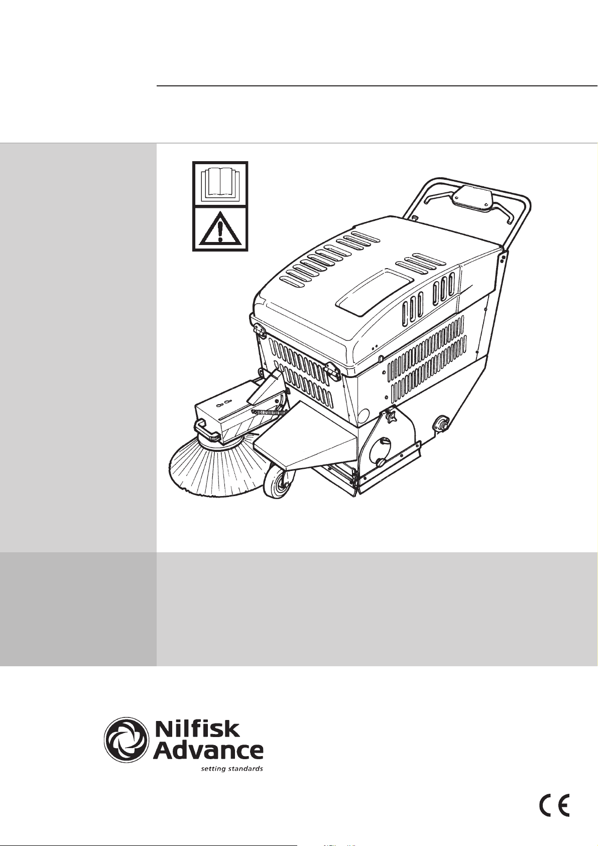
SW 700 P/B - SW 850 P/B
SW 5070 P/B - SW 5080 P/B
OPERATING INSTRUCTION
S31NUK5080(2)2001-01
Page 2
CONTENTS
S31NUK5080(2)2001-01
Model :
Serial No :
Power :
Tot al
Weight
Prod. No.
Max. axel rear :
Max. axel front :
Noise level :
Voltage :
Manufactured by:
Nilfisk - Advance Italia
26862 Guardamiglio (Lodi) - Italy
www.nilfisk-advance.com
A2
INTRODUCTION/GENERAL INFORMATION ............................................................................................. 1
UNPACKING .............................................................................................................................................. 2
TECHNICAL DATA ....................................................................................................................................3
CONTROL PANEL DESCRIPTION ............................................................................................................. 4
PREPARING A NEW MACHINE (battery version) .................................................................................... 5-7
PREPARING A NEW MACHINE (petrol version) ......................................................................................8
START-UP (battery version) ...................................................................................................................... 9
START-UP (petrol version) ....................................................................................................................... 10-11
USE OF THE MACHINE............................................................................................................................ 12-13
CENTRAL BRUSH ADJUSTMENT AND REPLACEMENT ....................................................................... 14-16
SIDE BRUSH ADJUSTMENT AND REPLACEMENT ...............................................................................17-18
FILTER CLEANING AND REPLACEMENT ............................................................................................... 19-20
MAINTENANCE ........................................................................................................................................21
MAINTENANCE (battery version)............................................................................................................. 22-23
MAINTENANCE (petrol version) .............................................................................................................. 24-25
SUMMARY TABLE (battery-operated version maintenance) ................................................................. 26
SUMMARY TABLE (petrol-operated version maintenance) ...................................................................27
OPTIONAL ACCESSORIES ...................................................................................................................... 28
SAFETY FUNCTIONS ...............................................................................................................................29
TROUBLESHOOTING ............................................................................................................................... 30-31
SERVICE ADDRESSES ............................................................................................................................32
Page 3

INTRODUCTION / GENERAL
S31NUK5080(2)2001-01
INFORMATION
INTRODUCTION
This manual will help you get the most from your Nilfisk SW 700 P/B - SW 850 P/B - SW 5070 P/B - SW 5080 P/
B. Read it thoroughly before operating the machine. Specifications and details are subject to change without prior
notice.
SPARE PARTS AND MAINTENANCE
Repairs, when required, should be performed by Nilfisk service personnel using Nilfisk original replacement parts
and accessories. Any "left" or "right" indication are always defined with reference to the machine forward movement direction. Call Nilfisk for repairs parts or service.
Please specify the Model and the Serial Number when discussing your machine.
MODIFICATION AND IMPROVEMENTS
Our company constantly improves its products and reserves the right to make changes and improvements at its
discretion without being obligated to apply such benefits to the machines that were previously sold.
NAME PLATE
The Model and the Serial Number of your machine are shown on the Nameplate located on the steering column.
This information is needed when ordering repair parts for the machine. Use the space below to note the Model and
the Serial Number of your machine for future reference.
MODEL SERIAL NUMBER
GENERAL SAFETY RULES
Carefully follow the rules described below to avoid injury to the operator and damage to the machine.
- Carefully read the labels on the machine, do not cover them for any reason and replace them immediately if they
become worn or damaged.
- The machine storage temperature should range between 0°C ÷ 40°C.
- The machine working temperature range is from 0°C ÷ 40°C.
- Humidity should range between 30% and 95%.
- Do not use the machine in an explosive atmosphere
- Do not use the machine as a transport vehicle.
- Do not allow the brushes to operate while the machine is stationary to avoid damaging the floor.
- In case of fire, use a powder extinguisher.
- Do not bump into shelves or scaffolding where there is a risk of falling objects.
- Adjust the operating speed to the floor conditions.
- Do not exceed the declared slope limits to avoid an unstable condition.
- When the machine is parked, remove the key and engage the parking brake.
- When machine-operating malfunctions occur, make sure that they are not caused by a lack of routine maintenance.
If not, request assistance from the service center.
- If parts must be replaced, request ORIGINAL spare parts from a dealer or Authorized Retailer.
- Before any maintenance operations, disconnect the electric power supply from the batteries.
- Do not remove guards which require the use of tools to be disassembled.
- Do not wash the machine with pressurized water, or with corrosive substances.
- A service center should inspect the machine every 200 hours of operation.
- The machine must be disposed of properly, because of the presence of toxic-harmful materials (battery acid, oil,
etc.) which are subject to standards that require disposal in special centers.
- The machine will not generate damaging vibration.
SAFETY- ACCIDENT PREVENTION
No accident prevention program is effective without the complete cooperation of the person directly responsible
for operating the machine. Most of the accidents that may occur in a company, on the job or during transfers are
caused by not observing fundamental safety rules. A careful and cautious user is the best guarantee against
accidents and is more effective than any type of prevention program. While using the machine pay attention to
your surroundings and people nearby, especially to children.
SAVE THESE INSTRUCTIONS
1
Page 4
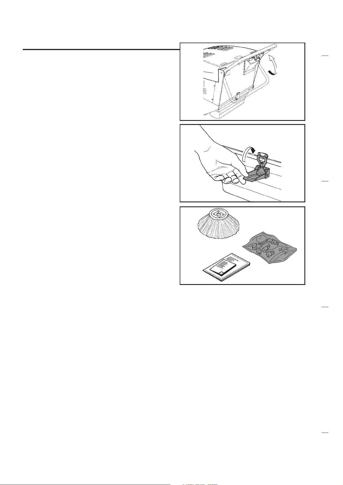
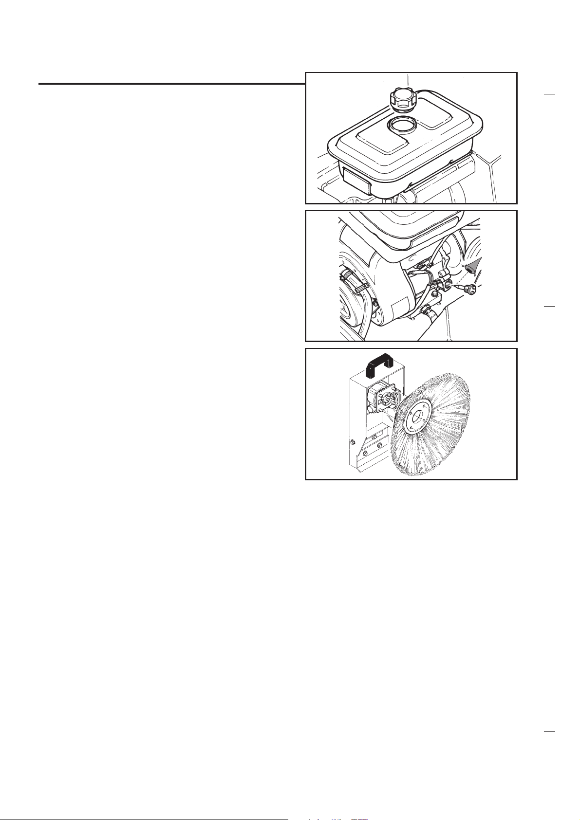
UNPACKING
Lift the driving handle and set it to the height
required.
Tighten the fixing screws at the end of the adjustment operation.
Remove the brush from the vaste container.
Replace the container and close it using the
special hook latch.
S31NUK5080(2)2001-01
Check that the following parts are present:
1- Brush (supplied with the machine).
2- Plastic bag with battery, connector for bat-
tery-loader and fuse (only electric model).
3- Technical documentation (spare parts cata-
logue, use and maintenance manual and,
for petrol version, engine use manual).
2
Page 5
TECHNICAL DATA
S31NUK5080(2)2001-01
VERSIONS
Voltage
Engine model
Power at 3600 RPM
Regulation at 3000 RPM
Starter
Main electric motor
Max forward speed
Max. slope
Main brush size
Main brush RPM
Side brush
Side brush RPM
Cleaning width with side brush
Front wheel (Nr 1)
Rear driving wheels (Nr 2)
Container capacity
Panel filter
Filter shaker
Length (to the driving handle)
Width
Height (to the driving handle)
Weight (without batteries)
Width (with batteries) (2)
Recommended battery (2)
Autonomy (2)
Total weight
Petrol tank
Engine oil
SW 700 P
SW 5070 B
12V
/
/
/
/
600W-3000RPM
max. 4,5 km/h
2%
diameter 265 mm (1)
lenght 500
450
diameter 420
80
700 mm
diameter 125
diameter 180
40lt
8 micron-2,5 m2
Manual/Electric
1180 mm
610 mm
910 mm
90 kg
134 kg
12 V-140 Ah
2 h
/
/
/
SW 700 P
SW 5070 P
/
Honda G150 K1-144cc
3,8 HP (2,8 kW)
3,0 HP (2,2 kW)
Manual
/
max. 4,5 km/h
2%
diameter 265 mm (1)
lenght 500
450
diameter 420
80
700 mm
diameter 125
diameter 180
40lt
8 micron-2,5 m2
Manual
1180 mm
610 mm
910 mm
/
/
/
2 h
100 kg
2,5 lt
0,7 lt
SW 850 B
SW 5080 B
12V
/
/
/
/
600W-3000RPM
max. 4,5 km/h
2%
diameter 265 mm (1)
lenght 600
450
diameter 420
80
820 mm
diameter 125
diameter 180
50lt
8 micron-2,5 m2
Manual/Electric
1180 mm
690 mm
910 mm
105 kg
149 kg
12 V-140 Ah
2 h
/
/
/
SW 850 P
SW 5080 P
/
Honda G150 K1-144cc
3,8 HP (2,8 kW)
3,0 HP (2,2 kW)
Manual
/
max. 4,5 km/h
2%
diameter 265 mm (1)
lenght 600
450
diameter 420
80
820 mm
diameter 125
diameter 180
50lt
8 micron-2,5 m2
Manual
1180 mm
690 mm
910 mm
/
/
/
2 h
115 kg
2,5 lt
0,7 lt
(1) For version "Carpet" diam. 245 mm. Only for battery version.
NOTE: Using the optional 240 Ah batteries the working autonomy will be one hour longer
(2)
and the machine weight will be 24 kg more.
3
Page 6
CONTROL PANEL DESCRIPTION
S31NUK5080(2)2001-01
PETROL VERSION
4
2
1
6
BATTERY VERSION
2
35
45
7
618
PETROL VERSION
1- Drive control lever
2- Flap lift-up lever
3- Start-up handle
4- Filter shaking lever
5- Engine on/off switch
6- Suction stop
3
BATTERY VERSION
1- Drive control lever
2- Flap lift-up lever
3- Display
4- Voltmeter/Hour meter button
5- Filter shaking lever (Standard)
6- On/off key electrical supply
7- Filter shaking push-button
8- Suction stop
4
Page 7
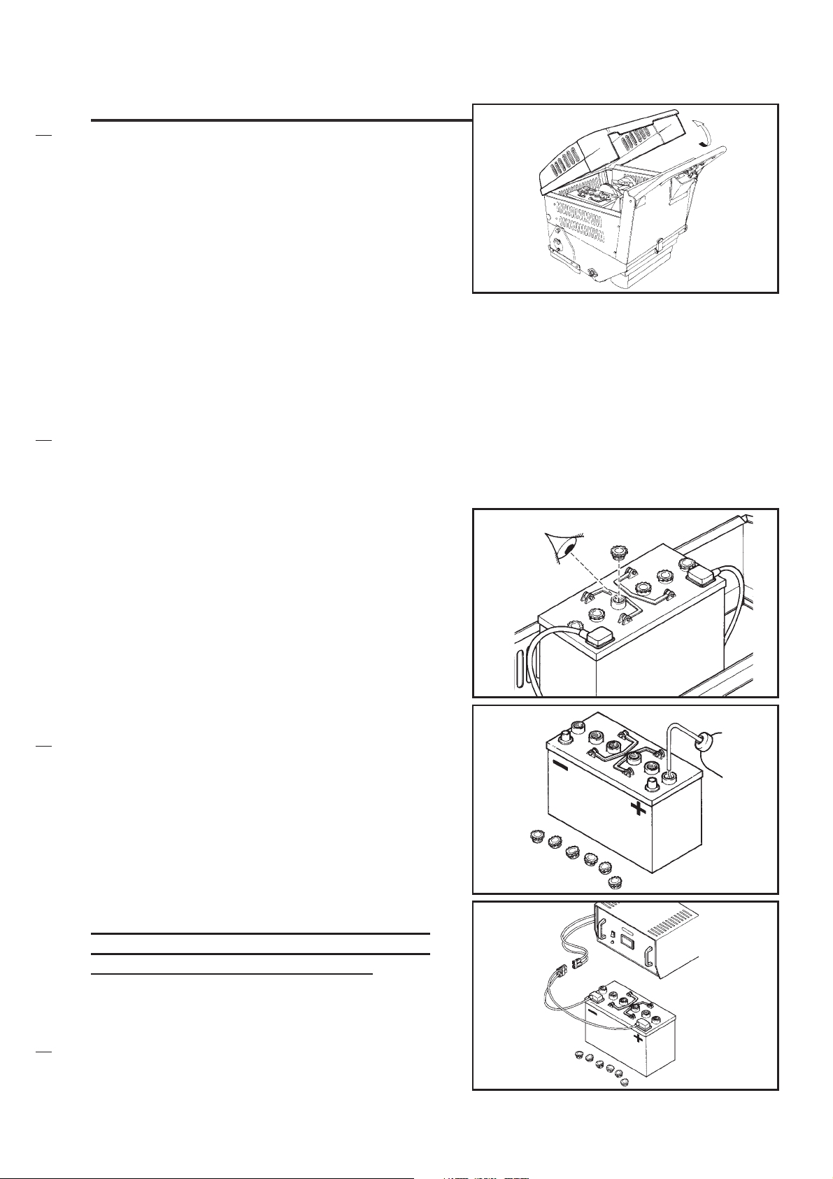
PREPARING A NEW MACHINE
(battery version)
Let us consider now the battery-operated machine. It requires one 12-volt battery (capacity:
140 Ah).
Alternatively, it is also possible to use two 6volt batteries with a serial connection and with
a higher capacity (for instance: 240 Ah).
According to the country where it is sold, there
are three possibilities:
1- Battery is supplied with the machine and it
is set, complete with acid solution and ready
to use.
2- Battery is supplied with the machine and it
is set (but not complete with acid solution).
3- Battery is not supplied.
Tilt the machines bonnet and check which op-
tion is applicable for your machine.
S31NUK5080(2)2001-01
If the battery is set, open one of the ventilation
caps to check whether it is complete with electrolyte.
If the battery is complete with electrolyte:
1a. Check for the level of the electrolyte and fill
up if necessary. (Fill up with destilled water
only).
1b. Carry out a recharge operation (see para-
graph MAINTENANCE) as specified in the
following pages.
Warning: Before starting the recharge operation, the connector of the battery must
be disconnected from the machine.
During recharging, all batterys caps have to
be open.
When the recharge is concluded, the batterys
connector can be reconnected to the machine.
5
Page 8
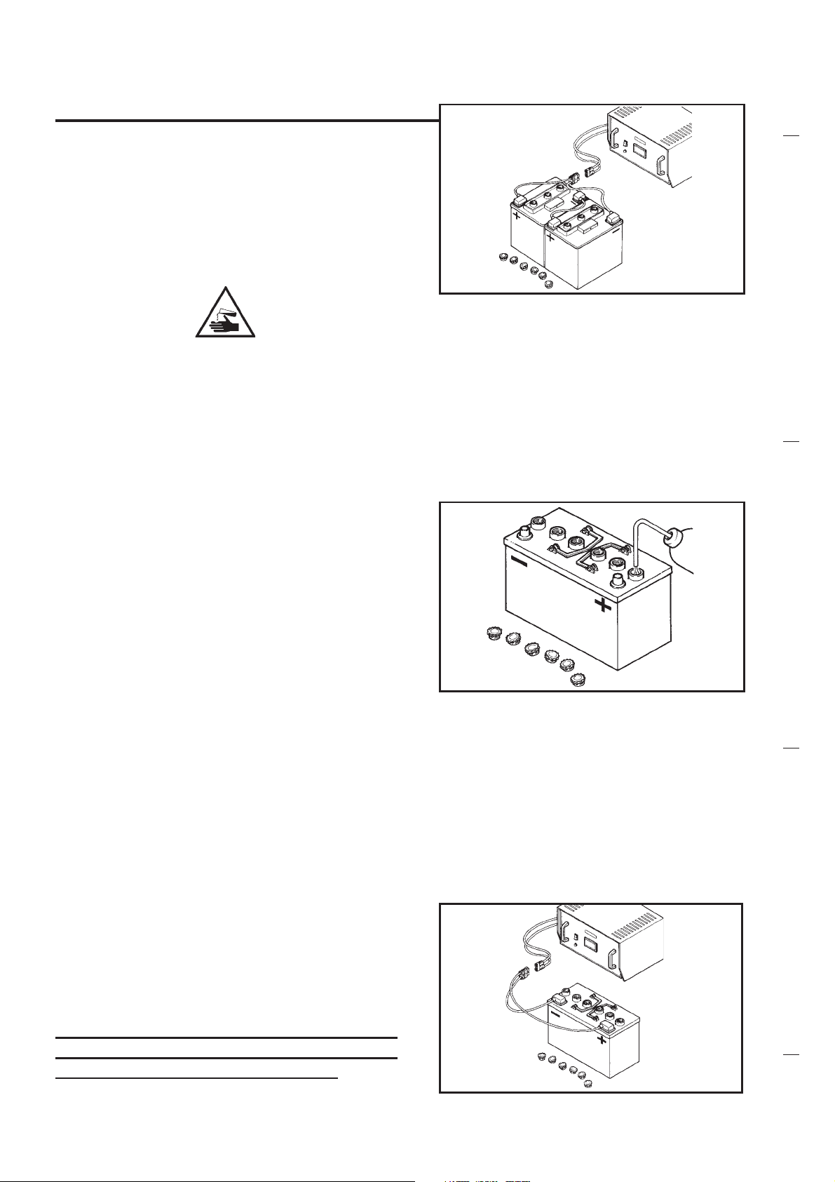
PREPARING A NEW MACHINE
(battery version)
2- If the battery is set without acid solution it
must be filled up (density from 1.27 to 1.29
kg/lt at 25°C) according to the instructions
contained in next paragraph.
S31NUK5080(2)2001-01
BATTERIES FILLING UP WITH ACID SOLUTION
Please pay a strict attention when working
with sulphuric acid, as it is corrosive. If it
comes in contact with the skin or the eyes,
wash abundantly with water and call a doctor.
Battery has to be filled up in a properly ventilated area.
Fill up each element of the battery with acid;
the right level is roughly 10 ÷ 15 mm over the
electrodes.
After one hour fill up with acid if necessary.
Let battery rest for one hour and proceed with
the charging (please refer to the paragraph
MAINTENANCE). When carrying out the recharge operation, all the caps of the battery
have to be open.
Warning! Before starting the recharge operation, the connector of the battery must
be disconnected from the machine.
6
Page 9
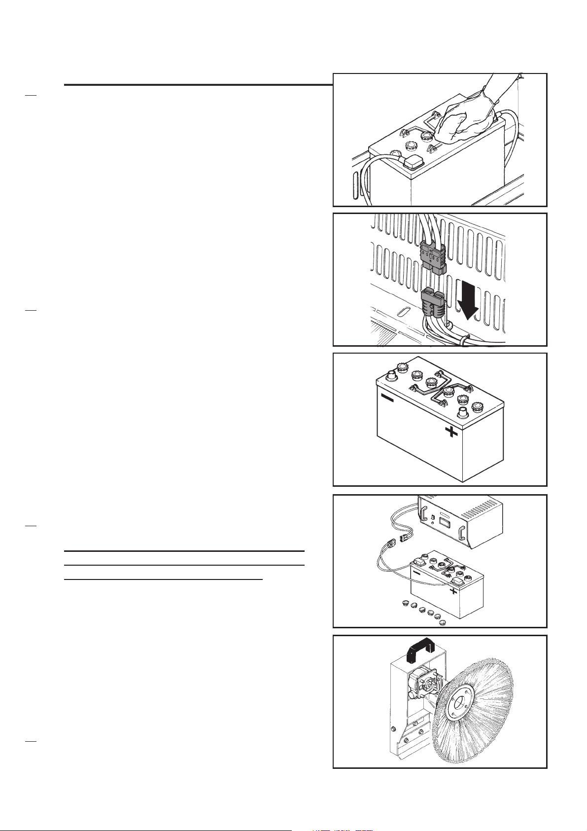
PREPARING A NEW MACHINE
(battery version)
At the end of the recharge operation close all
the caps of the batteries, clean their upper part
and remove all possible acid remains.
Connect the batterys connector to the machine.
S31NUK5080(2)2001-01
3- If the machine is supplied with no battery,
they have to be procured and mounted.
It is recommended to use the service of qualified personnel to choose and to install the new
battery.
The electric connection cables that are supplied
together with the machine can be used for the
battery connection.
Warning: Before starting the recharge operation, the connector of the battery must
be disconnected from the machine.
Place the brush as per the figure and make
sure that the fixing profiles match perfectly with
the relevant holes. Coupling may be helped
thanks to a light pressure of your hand.
Now the machine is ready to be used.
7
Page 10
PREPARING A NEW MACHINE
(petrol version)
Let us now consider the machine in the gasoline-fed engine version.
Fill the tank with unleaded petrol.
Check for the engine oil level and fill up if necessary. Please read the use manual of the
Honda engine.
S31NUK5080(2)2001-01
Place the brush as per the figure and make
sure that the fixing profiles match perfectly with
the relevant holes. Coupling may be helped
thanks to a light pressure of your hand.
Now the machine is ready to be used.
8
Page 11
START-UP
(battery version)
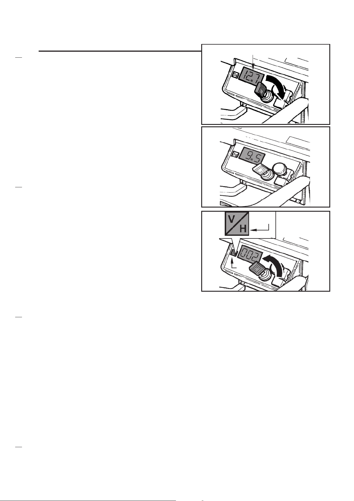
Insert the ignition key, turn it clockwise: the main
motor will then be started-up while display "A"
will show the battery voltage level.
Check for the battery charge status by means
of the specially-conceived display.
The display has two functions: voltmeter and
hour meter. The voltmeter includes a stop function for under-voltage that disables automatically all functions, including the drive, when the
battery reaches a voltage level of 9,5 volts
(flashing display). In this case, you must proceed with the battery recharging operation.
Please see chapter MAINTENANCE.
If you wish to see on the display the number of
working hours of the machine (hour-counting
function) press once the display data selection
button B. If you press another time the data
selection button, the operating minutes will be
displayed. If you press another time or, alternatively, if you wait for roughly 10 seconds, the
battery voltage will be displayed.
If you wish to turn off the machine, just turn the
key counterclockwise.
S31NUK5080(2)2001-01
A
A
B
B
9
Page 12
START-UP
(petrol version)
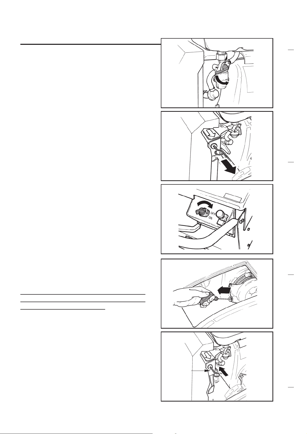
N.B.: Please read the Honda engine instruc-
tions manual.
Turn the gasoline tap as per the figure in order
to enable the flow to the carburettor.
Move the starter lever as per the relevant figure.
N.B.: Do not use the starter lever if the en-
gine is hot and if the external temperature is high.
S31NUK5080(2)2001-01
Turn the selector onto "ON".
Slightly pull the starter handle until you feel it
becomes harder and then pull abruptly.
Warning: Do not let the starter handle return to its position quickly; please follow it
in its downwards movement.
When the engine is slightly warm, slowly bring
the starter lever "A" to its original position.
The rpm are fixed and must be kept constant.
A
10
Page 13
START-UP
(petrol version)
S31NUK5080(2)2001-01
If you wish to stop the engine, turn selector "C"
onto the "OFF" position.
and turn tap "D" onto the "OFF/CLOSED" position.
C
D
11
Page 14

USE OF THE MACHINE
Lower the side brush.
BATTERY VERSION
S31NUK5080(2)2001-01
When the motor is in operation, make sure that
handle "A" has been lowered (suction enabled);
if you pull the drive lever "B" you can adjust the
running speed depending onto the quality and
onto the quantity of the debris to be picked up.
The machine looses traction releasing the lever "B".
PETROL VERSION
When the engine is running, make sure that
handle "A" has been lowered (suction enabled);
if you pull the drive lever "B" you can adjust the
forward speed depending onto the quality and
onto the quantity of the debris to be picked up.
The machine looses traction releasing the lever "B".
A
B
A
B
To collect light and bulky waste materials, lift
the flap using the the left side lever.
(Do not keep pushing onto the lever for a long
time in order not to reduce the suction capability of the machine).
In case it is necessary to work onto wet ground,
it is of utmost importance to disable the suction
function (in order not to damage the papermade filter); just pull (upwards) handle "A" as
shown in the figure.
If you wish to enable the suction, lift lever "B"
as shown in the figure.
12
A
B
Page 15

USE OF THE MACHINE
For efficient suction operation, the air filter must
always be clean.
Activate the filter shaker (you can also perform
this operation when the machine is working) by
pulling and releasing the handle as shown in
the figure.
Warning: always disable the suction function during this operation.
Repeat this operation every 15-20 minutes depending on the kind of dirt that is picked up,
before emptying the container and at the end
of the work.
S31NUK5080(2)2001-01
Before leaving the machine, please make sure
that:
- the side brush is not in contact with the ground.
BATTERY VERSION
The start-up key is in the "OFF" position.
PETROL VERSION
The selector is in the "OFF" position.
The vaste container should be emptied after
each work period and when ever is full.
BATTERY VERSION
This version includes, as an optional accessory,
the electrically-operated filter-shaker which is
controlled by means of push-button "A".
When using the filter shaker the suction fan will
automatically stop.
13
A
Page 16

CENTRAL BRUSH ADJUSTMENT
AND REPLACEMENT
S31NUK5080(2)2001-01
Warning: these operations must be carried
out with the machine off, the key switched
off (for battery-operated version), selector
in "OFF" position (for petrol-operated version) and with the machine on even floor.
When the main brush is fairly worn, its height
must be adjusted to recover as much of the
brush consumption as possible.
Loosen the knobs "A" on both sides of the
machine, lower the brush to the ground taking
the "B" indicator to the right position in the direction shown in the figure. The "B" indicator
must be placed in the same position on both
sides of the machine.
To make sure that the main brush has been
properly adjusted, perform the following operations: let the brush rotate with the machine not
in operation and on a flat ground; then make
sure that the print left by the brush onto the
ground is from 2 to 4 cm. wide.
A
A
B
If the brush does not operate efficiently repeat
the adjustment operation.
When the brush is completely worn-out, it must
be replaced.
In order to perform this operation, just lift the
bonnet so as to disconnect the safety device;
loosen the knob on the left side of the machine,
as shown in the figure.
Remove the cover by pushing it down.
14
Page 17

CENTRAL BRUSH ADJUSTMENT
AND REPLACEMENT
Pull out the worn brush.
If necessary, remove the hub from the brush
stem and place it onto the new brush; please
do not change the direction of the bristles
(please see following figure).
Note:
Before inserting the brush, replace the adjustment devices in the position that is farthest away
from the ground.
S31NUK5080(2)2001-01
Insert the new brush and make sure that the
hub is inserted in the entrainment device.
Rotation direction and direction of the central
brush bristles.
Replace the cover,
15
Page 18

CENTRAL BRUSH ADJUSTMENT
AND REPLACEMENT
and tighten the lock knob.
ADJUSTING OF THE MAIN BRUSH
IN THE CARPET VERSION
In the carpet version machine it will be necessary
to adjust the distance from the floor of the main
brush as indicated in the adhesive.
According to the high of the carpet hair to be
cleaned the screw "A" will be a little bit loosen in
order to adjust the fixing plate central brush in
the correct position from 1 to 10.
S31NUK5080(2)2001-01
A
The brush must be adjusted so that it can just
touch the carpet.
A
16
Page 19

SIDE BRUSH ADJUSTMENT
AND REPLACEMENT
When the side brush is fairly worn, its height
must be adjusted to recover as much of the
brush consumption as possible.
Lower the brush (motor on).
Please make sure that the ground contact area
is as shown in the figure.
S31NUK5080(2)2001-01
Warning: these operations must be carried
out with the machine off, the key switched
off (for battery-operated version), selector
in "OFF" position (for petrol-operated version) and with the machine on even floor.
If you need to change the ground contact area,
just slacken counternut "A" and turn screw "B"
keeping nut "C" still. Eventually tighten
counternuts "A" and "C".
Restart the brush and make sure that the
ground contact area is as required. If necessary, just repeat the adjusting operation until
reaching the right position.
B
C
A
When the brush is remarkably worn out, it is
necessary to replace it. Just press the two tabs
inwards and remove the brush.
Reinstall the new brush by carrying out the reverse operation and pushing it with your hands.
17
Page 20

SIDE BRUSH ADJUSTMENT
AND REPLACEMENT
Note: when the brush are replaced check that
the height is adjusted to its original position, corresponding to a new brush.
If you need to change the ground contact area,
just slacken counternut "A" and turn screw "B"
keeping nut "C" still. Eventually tighten
counternuts "A" and "C".
S31NUK5080(2)2001-01
C
B
A
18
Page 21

FILTER CLEANING
AND REPLACEMENT
The filter requires a periodical and complete
cleaning operation.
Remark:
Depending onto the customers request, the
machine is supplied with two options :
1- Manually-operated filter shaker (battery-fed
or gasoline-fed version).
2- Electrically-operated filter shaker (only bat-
tery-operated version).
Lift the bonnet to remove the filter.
Turn the levers 180° outwards onto the sides
of the filter fixing cover.
S31NUK5080(2)2001-01
Spread the lever supporting brackets towards
outside, as shown in the figure.
Disconnect the cables of the electric filter shaker
motor (if installed) in order to move forward the
filter fixing cover.
Slightly lift the manual filter shaker in order to
remove the filter.
19
Page 22

FILTER CLEANING
AND REPLACEMENT
Remove the panel filter.
Clean the filter by means of pressed air (do not
exceed a pressure level of 6 bar) onto the side
with the protection net.
If you discover damages onto the filter or if it is
not possible to clean it in the right way, just replace it.
Ask your dealer for the original spare part you
need.
Polyester-made washable filters are also available.
S31NUK5080(2)2001-01
After cleaning, reinstall both the filter and the
fixing cover.
Turn the two cover side levers inwards.
Reconnect the cable of the electric filter shaker
motor (if installed).
20
Page 23

MAINTENANCE
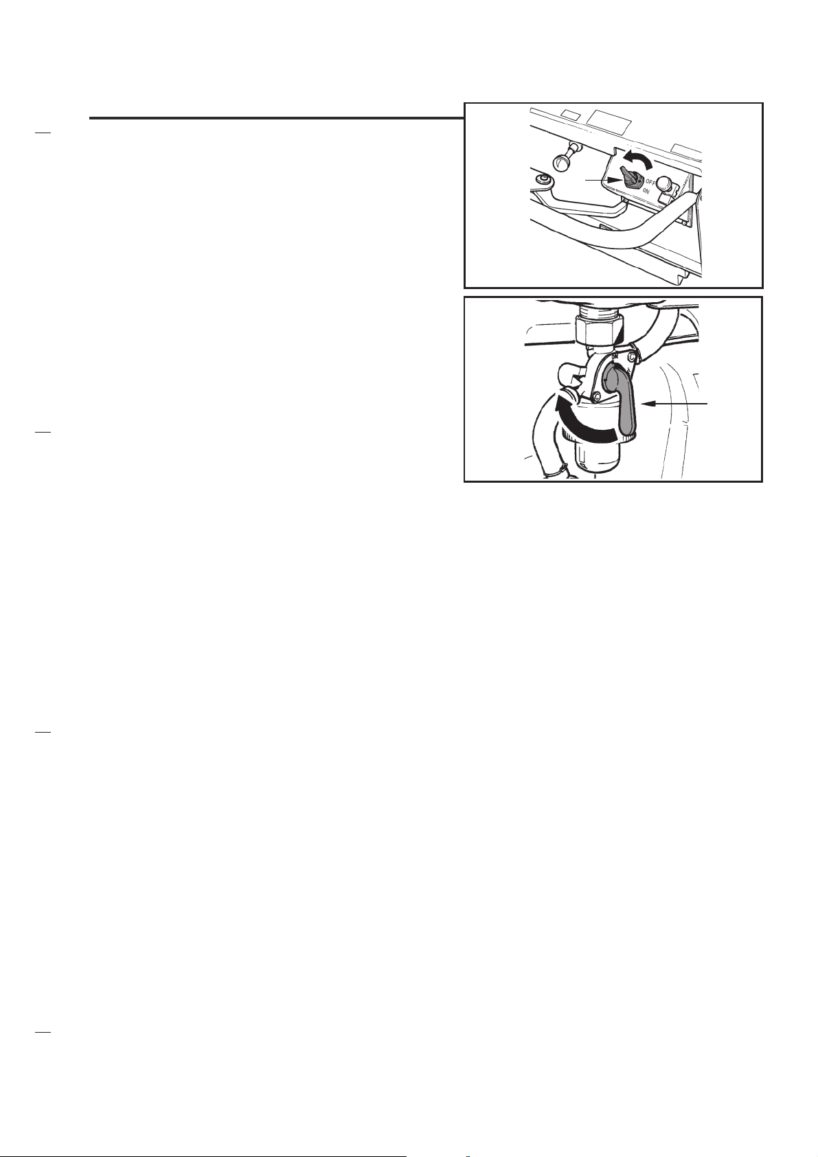
ADJUSTING THE TRACTION COMMAND
CABLE
When it is neccesary, tighten the traction control cable.
The adjustment device is placed as shown in
the figure, for Petrol version.
The location of the adjustment device for Battery version, is as shown in the figure.
S31NUK5080(2)2001-01
To carry out the adjustment, loosen the lock nut
"A" and turn the adjusting nut "B".
Check the correct tightening, operating the traction control lever.
A
B
21
Page 24

MAINTENANCE
(battery version)
BATTERY CONTROL AND RECHARGE
Please perform a periodical control of the electrolyte level inside the battery. Lift the bonnet
and open the cells caps. If necessary, fill up
the cells with distilled water.
The electrolyte level has to be roughly 10 ÷ 15
mm over the electrode.
After filling up, close the cells with the caps and
clean the upper surface of the battery.
S31NUK5080(2)2001-01
Warning: Be extremely careful! The batterys
liquid is corrosive. If it comes in contact with
the skin or the eyes, wash repeatedly with
water and consult a doctor.
When necessary, recharge the battery in compliance with the following instructions:
- turn off the machine by means of the main key;
- lift the bonnet;
- disconnect the connector of the battery
from the machine;
- recharge has to be performed in a properly
ventilated area;
- open all caps of the cells (or elements) of the
battery;
- connect the battery connector to the battery
charger;
- connect the battery charger to the mains (the
mains voltage level and the frequency have
to match the corresponding levels that are
applicable for the battery charger).
22
Page 25

MAINTENANCE
(battery version)
At the end of the recharge disconnect the battery from the battery charger and reconnect it
to the machine. Close all caps and clean the
upper surface of the battery.
S31NUK5080(2)2001-01
23
Page 26

MAINTENANCE
(petrol version)
We remind you that it is necessary to carefully
read the Honda engine use and maintenance
manual and we offer you some other practical
advice:
Check the engine oil level twice a week by
means of the specially-conceived gauge; to top
up use the oil indicated in the engine Use and
Maintenance manual.
Remark: Replace engine oil the first time after
20 operating hours or within one
month. Afterwards, do it after 100
hours or within 8 months.
S31NUK5080(2)2001-01
The engine oil can be changed as follows:
Disconnect the exhaust tube and insert it into
the specially-conceived opening on the side of
the machine.
Unscrew the cap connected with the engine oil
level gauge.
Remove the strap and the plug from the tube
and allow the used oil to drain out.
Note: Make this operation when the engine
is warm.
Collect dirty oil in the special containers and
dispose of it in compliance with the current regulations in force in your country.
Remark: keep exhaust tube open and up dur-
ing filling.
24
Page 27

MAINTENANCE
(petrol version)
Get a funnel and feed with the new oil (the one
specified in the Use and Maintenance for
Honda motor) through the level control opening; put the cap and the gauge back to their
original positions and reinstall the closing cap
onto the exhaust tube.
After filling operation, check the oil level with
the special dip stick.
Periodically check the motor air filter.
If necessary, wash the filter "A" with water and
soap or with another home-use detergent.
Squeeze and dry it properly.
For the air filter "B" cleaning, blow with com-
pressed air (no more than 6 bar).
Reinstall both the filter and the cover.
A
S31NUK5080(2)2001-01
B
25
Page 28

SUMMARY TABLE
S31NUK5080(2)2001-01
(battery-operated version maintenance)
Warning: these operations must be carried out with the machine off and the key switched
off.
All periodic or extraordinary maintenance operations must be performed by skilled personnel, or by an authorised service centre.
Note: The battery life will depend on the level or periodic maintenance (checking the electro-
lyte level and density). If the machine does not run for a long time (ex. 4 to 6 weeks) it
will be necessary to recharge the batteries to make sure that their voltage does not go
under 9,5 Volt. Infact unused batteries get a self-discharge.
CONTROL
Battery liquid level and
voltage
Check the carbon brushes of the
electric motor, and replace them if
worn-out
Belt tightening
Filter shaker
Nut and screw tightening
Side and central
brush condition
Panel filter cleaning
Filter, gasket seal, flaps
Control devices cable
adjustment
UP ON
DELIVERY
EVERY
30 h
OR EVERY
TWO WEEKS
EVERY
50 h
EVERY
100 h
EVERY
500 h
26
Page 29

SUMMARY TABLE
S31NUK5080(2)2001-01
(petrol-operated version maintenance)
Warning: these operations must be carried out with the machine off.
All periodic or extraordinary maintenance operations must be performed by skilled personnel, or by an authorised service centre.
For any maintenance work on the engine, refer to its instruction manual.
CONTROL
Engine filter cleaning
Panel filter cleaning
Engine oil level check
Engine oil
replacement
Belt tightening
Filter shaker
Nut and screw tightening
Side and central brush
condition
Filters, gasket seal, flaps
Control devices cable
adjustment
UP ON
DELIVERY
FIRST TIME
TWICE
A
WEEK
EVERY
20 h
FIRST TIME
OR WITHIN
ONE MONTH
EVERY
50 h
EVERY
100 h
OR WITHIN
EIGHT MONTHS
27
Page 30

OPTIONAL ACCESSORIES
High capacity batteries for electrical version.
Battery charger.
S31NUK5080(2)2001-01
Different kinds of brushes (central and side) for
various applications.
Polyester-made washable filter.
For all optional accessories, please call your
dealer.
28
Page 31

SAFETY FUNCTIONS
The battery-operated version is equipped with
a display.
The display has two functions: voltmeter and
hour meter. The voltmeter includes a stop function for under-voltage that disables automatically
all functions, including the drive, when the battery reaches a voltage level of 9,5 volts (flashing display). In this case, you must proceed with
the battery recharging operation (please see
chapter "MAINTENANCE").
S31NUK5080(2)2001-01
SAFETY MICROSWITCH
It is activated when the machine bonnet is lifted
up.
By doing this, you stop the electrical motor or
the petrol engine and consequently all parts in
movement.
CENTRAL BRUSH SAFETY DEVICE
The operator has to lift the bonnet to reach the
lid latch of the main brush compartment.
When the bonnet is lifted the microswitch is
activated, thus stopping the main brush.
29
Page 32

TROUBLESHOOTING
S31NUK5080(2)2001-01
BATTERY VERSION
THE MACHINE DOESNT START
THE MACHINE HAS NO TRACTION 1) CHECK THE TENSION BELT
THE MACHINE DOESNT SWEEP
THE MAIN BRUSH DOESNT TURN
1) CHECK THE BATTERIES CHARGING AND EFFICIENCY
2) CHECK THE BATTERY/KEY C1 CONNECTIONS
3) CHECK THE SWITCH KEY (C1)
4) CHECK THE MOTOR EFFICIENCY AND THE SAFETY MICRO
CONNECTIONS (MSW 1)
5) CHECK THE SOLENOID STARTER (TL 1)
6) CHECK THE FUSE F1 - it has to be added in the electric wir-
ing
7) CHECK THE MOTOR EFFICIENCY (M1)
2) CHECK THE ADJUSTING OF THE TRACTION LEVER CABLE
3) CHECK THE ADJUSTING TRACTION TRANSMISSION WHEEL
1) CHECK EVENTUAL OBSTACLES TO THE MAIN BRUSH TURN-
ING (ROPES, WOODS) AND BALL BEARINGS
2) CHECK THE BELT AND THE BELT TIGHTENER
3) CHECK THE ADJUSTING MAIN BRUSH HEIGHT
1) CHECK THE BELT TENSION
2) CHECK THE REDUCTION GEAR EFFICIENCY
THE MACHINE DOESNT SUCKS
THE FILTER SHAKER DOESNT WORK 1) CHECK THE ELECTRIC CONNECTIONS
WHILE THE MACHINE IS WORKING
ALL FUNCTIONS STOP
1) CHECK THE EVENTUAL CLOGGED FILTER
2) CHECK THE CORRECT FUNCTIONING OF THE CABLE AND
MECHANISM USED TO DISCONNECT THE FAN
2) CHECK THE EFFICIENCY OF THE WORKING BUTTON (C2)
3) CHECK THE RELAY EFFICIENCY (RL1)
4) CHECK THE MOTOR EFFICIENCY (M2)
1) CHECK THE CHARGING BATTERIES CONDITION (POSSIBLE
INTERVENTION OF THE BATTERY UNDERVOLATAGE CUT OUT. - 9,5 Volts -)
2) CHECK THE FUSE F1. CONTROL THE ABSORPTION OF THE
ELECTRIC MOTOR M1; IF THE ABSORPTION IS OVER 80 Amp
CHECK ANY EVENTUAL OBSTACLE FOR A CORRECT MAIN
BRUSH TURNING, THEN CHECK THE BRUSH HEIGHT ADJUSTING
30
Page 33

TROUBLESHOOTING
PETROL VERSION
THE ENGINE DOESNT SWITCH 1) CHECK IF THERE IS PETROL IN THE TANK
2) CHECK IF THE TANK TAP IS IN POSITION ON
3) CHECK THE CORRECT POSITION /EFFICIENCY OF THE SWITCH
ON/OFF (C1)
4) CHECK THE CONNECTIONS AND EFFICIENCY OF THE SAFETY
MICRO SWITCH MSW
5) INSPECT THE STOPPING ELECTRIC WIRE IN ORDER TO
CHECK ANY EVENTUAL SHORT CIRCUIT (LOSS OF INSULATION) OF THE CABLE
6) CHECK THE AIR FILTER AND SPARK PLUG CONDITION OF THE
PETROL ENGINE (SEE MAINTENANCE CHAPTER)
S31NUK5080(2)2001-01
THE ENGINE DOESNT STOP
THE MACHINE PERFORMANCE IS
NOT GOOD
THE ENGINE STOPS 1) CHECK THE FUEL LEVEL
FOR THE CHAPTERS: "THE MACHINE DOESNT SWEEP", "IT DOESNT SUCKS", "THE SIDE BRUSH
DOESNT TURN", SEE CHAPTER BATTERY VERSION.
1) CHECK THE CORRECT POSITION/EFFICIENCY OF THE
SWITCH ON /OFF (C1)
2) CHECK THE STOPPING ENGINE CABLE (WIRE) CONNECTIONS.
1) REVOLUTION PER MINUTE (RPM) OF THE ENGINE: ADJUST IT
UP TO 3000 RPM
2) CHECK THE AIR FILTER AND SPARK PLUG OF THE PETROL
ENGINE
3) CHECK THE EFFICIENCY,CONNECTIONS AND INSULATION
OF THE SWITCH ON/OFF (C1) OF THE SAFETY MICRO
SWITCH (MSW) AND OF THE ELECTRIC WIRE FOR STOPPING ENGINE
31
Page 34

SERVICE ADDRESSES
S31NUK5080(2)2001-01
AUSTRALIA
Nilfisk-Advance Pty. Ltd.
ACN 003 762 623
Head office: 17 Leeds Street, Rhodes, N. S. W. 2138
Tel. (02) 9736 1244 - Fax (02) 9736 3910
Customer Responce Centre:
Tel.1 800 011 013
BELGIQUE/BELGIË/LUXEMBOURG
Nilfisk-Advance s.a./n.v.
Doornveid/Sphere Business Park
Industrie Asse 3, nr 11- bus 41
1731 Zellik-Asse
Tel.(02) 467.60.50 Fax (02) 463.44.16
CANADA
Nilfisk-Advance Ltd
396 Watline Avenue
Mississauga, Ontario L4Z 1X
Tei.(905) 712-3260 - Fax (905) 712-3255
DANMARK
Nilfisk-Advance Nordic A/S
Myntevej 3, 8900 Randers
Tel.86 42 84 33 - Fax 86 41 19 55
DEUTSCHLAND
Nilfisk-Advance AG
Siemensstraße 25-27
25462 Rellingen
Tei. (04101) 3990 - Fax (04101) 399191
Zentraler Kundenservice / Customer Hotline
Tel.0180 53 56 797
ESPAÑA
Nilfisk-Advance, S.A.
Torre DAra
Passeig dei Rengie, 5 -P1.10
E-08302 Mataró (Barcelona)
Spain
Tel.: 93 741 2400
Fax: 93 757 8020
nilfisk@nilfisk-advance.es
Teléfono nacional de servicio Comercial: 902 200 201
Teléfono nacional ce servicio Técnico: 902 300 301
Delegaciones, Distribuidores y Servicio Técnico a domicilio en todas las
regiones de España
FINLAND/SUOMI
Oy Tecalemit A B
Hankasuontie 13, 00390 Helsinki
Tel.(89) 547 701- Fax (89) 547 1779
FRANCE
Nilfisk-Advance S.A
BP 246
91944 Courtaboeuf Cedex
Tel.(01) 69.59.87.00 Télécopie (01) 69.59.87.01
PORTUGAL
Nilfisk-Advance Lda.
Rua Cândido de Figueiredo, 91-i, 1500-133 LISBOA
Tel. 01/784142-Fax 01/785613
Porto 02/526766 - Fax 02/520739
Açores 096/628092/3 - Fax 096/628129
Madeira 091/228965 - Fax 091/228796
SCHWEIZ / SUISSE
Nilfisk-Advance AG
Ringstrasse 19, 9533 Kirchberg/Wil
Tel.719 23 52 83 - Fax 719 23 84 44
SINGAPORE
Nilfisk-Advance Pte. Ltd.
10, Woodiands Loop
Singapore 738388
Tel. (65) 759 9100 - Fax (65) 759 9133
SVERIGE
Nilfisk-Advance AB
Sjöbjörnsvägen 5, 117 67 Stockholm
Tel. 085 55 944 00 - Fax 085 55 944 30
TAIWAN
Nilfisk-Advance Ltd
1 F, No.23, Lane 132, Sec. 2
Ta An Road, Taipei
Tel.700 22 68 - Fax 784 08 43
UNITED KINGDOM
Nilfisk-Advance limited
Newmarket Road
Bury St. Edmunds
Suffolk IP 33 35R
Tel.(01284) 763163 - Fax (01284) 750562
USA
Nilfisk-Advance inc.
14600 21st Avenue North
Plymouth, MN 55447-3408
Tel. +1612 475 2235 - Fax 1612 473 1764
Nilfisk-Advance of America, lnc.
300 Technology Drive
Malvern, PA 19355
Tel. (610) 647 647-6427
ÖSTERREICH
Nilfisk-Advance GmbH
Vorarlberg Allee 46
1230 Wien
Tel. 1 616 58 30 - Fax 1616 58 30 40
HONG KONG
Nilfisk-Advance Ltd
2001, 20/F HK Worsted Mills
Industrial Building
31-39 Wo Tong Tsui Street
Kwai Chung, N.T.
Tel. 2427 59 51- Fax 2487 5828
IRELAND
Nilfisk-Advance Ltd
28 Sandyford Office Park
Dublin 18
Tel. +353 12943838 - Fax +353 12943845
ITALIA
Nilfisk-Advance Italia S.p.A
Località Novella Terza
26862 Guardamiglio (Lodi) Italia
www.nilfisk-advance.com
Phone: +39 0377 451124 - Fax: +39 0377 51443
JAPAN
Nilfisk-Advance Inc.
3-4-9 Chigasaki Minami
Tsuzuki-Ku Yokohama 224
Tel.045-942-7741- Fax 045-942-6545
MALAYSIA
Nilfisk-Advance Sdn Bhd
Lot 2, 1st. Floor
Lorong l9/1A
46300 Petaling Jaya
Selangor Darul Ehsan
Tel.03-7568188/03-7568189/03-7568388- Fax 03-7566828
NEDERLAND
Nilfisk-Advance B.V.
Flevolaan 7, Postbus 341
1380 AH Weesp
Tel. 0294-462121- Fax 0294-430053
NEW ZEALAND
Nilfisk-Advance Limited
477 Great South Road, Penrose
Auckland
Tel. (09) 525 0092 - Fax (09) 525 6440
NORGE
Nilfisk-Advance AS
Enebakkvn, 119, 0680 Oslo, Postboks 196, Manglerud, 0612 Oslo
Tel. 22 08 63 50 - Fax 22 08 63 63
Distriktsrepresentanter over hele landet
32
Page 35

COD. S31NUK5080(2)2001-01 Graphic project PROMIND Brescello Italy
Nilfisk-Advance Italia S.p.A
Località Novella Terza
26862 Guardamiglio (Lodi) Italia
www.nilfisk-advance.com
Phone: +39 0377 451124
Fax: +39 0377 51443
Printed in Italy
 Loading...