

Page 1
3051 - 3101 - 3151
040/22 - 100/28 - 150/36
3051T - 3101T - 3151T
040/22T - 100/28T - 150/36T
MANUALE ISTRUZIONI
INSTRUCTION MANUAL
Codice n° - Code nr. : C19-I-GB-1000
Edizione / Edition : 12/98
Page 2

mod. 3051 - 3101 - 3151
INDICE
1- Informazioni generali .................................................................................... pag. 1
1.1 Introduzione.............................................................................. pag. 1
1.2 Personale addetto al funzionamento della macchina............... pag. 2
1.3 Simboli utilizzati nel presente manuale .................................... pag. 3
1.4 Collaudo e garanzia ................................................................. pag. 4
1.5 Istruzioni per le richieste di intervento...................................... pag. 4
1.6 Esclusione di responsabilità..................................................... pag. 4
1.7 Limitazioni alla riproduzione e divulgazione del manuale ........ pag. 5
2- Descrizioni generali....................................................................................... pag. 7
2.1 Dati anagrafici del costruttore................................................... pag. 7
2.2 Dati di identificazione ............................................................... pag. 7
2.3 Parti principali........................................................................... pag. 9
2.4 Descrizione della macchina...................................................... pag. 13
2.5 Principio di funzionamento ....................................................... pag. 14
2.6 Dimensioni di ingombro e pesi ................................................. pag. 15
2.7 Dati tecnici................................................................................ pag. 17
2.8 Uso previsto ............................................................................. pag. 19
2.9 Rumore aereo .......................................................................... pag. 20
2.10 Vibrazioni.................................................................................. pag. 20
2.11 Emissioni di gas o radiazioni.................................................... pag. 20
2.12 Campi elettromagnetici............................................................. pag. 20
2.13 Usi non consentiti..................................................................... pag. 21
© C.F.M. S.p.A.
Tutti i diritti riservati
All rights reserved
3- Prescrizioni di sicurezza............................................................................... pag. 23
3.1 Prescrizioni generali ................................................................. pag. 23
3.2 Targhe di avvertenza................................................................ pag. 24
3.3 Dispositivi di sicurezza ............................................................. pag. 27
4- Movimentazione e consegna........................................................................ pag. 29
4.1 Consegna e movimentazione dell'aspiratore ........................... pag. 29
4.2 Pesi e dimensioni dellla macchina imballata............................ pag. 30
4.3 Stoccaggio................................................................................ pag. 31
4.4 Disimballo e modalità di smaltimento ....................................... pag. 31
5- Installazione ................................................................................................. pag. 33
5.1 Predisposizione lavori a carico del Cliente............................... pag. 33
5.2 Collegamento alla rete elettrica................................................ pag. 33
5.3 Verifica corretto allacciamento elettrico.................................... pag. 36
Page 3

mod. 3051 - 3101 - 3151
6- Uso dell'aspiratore ........................................................................................ pag. 37
6.1 Comandi................................................................................... pag. 37
6.2 Avviamento............................................................................... pag. 38
6.3 Arresto...................................................................................... pag. 40
6.4 Corretto utilizzo dell'aspiratore ................................................. pag. 40
6.5 Pulizia del filtro primario (solo mod. 3151) ............................... pag. 41
6.6 Svuotamento del contenitore.................................................... pag. 42
7- Manutenzione ................................................................................................. pag.45
7.1 Premessa ................................................................................. pag. 45
7.2 Controlli effettuati nei nostri stabilimenti................................... pag. 45
7.3 Controlli e verifiche all'avviamento ........................................... pag. 47
7.4 Manutenzione periodica ........................................................... pag. 47
7.5 Operazioni di manutenzione ordinaria...................................... pag. 49
7.6 Sostituzione del cavo di alimentazione .................................... pag. 55
7.7 Ricambi .................................................................................... pag. 58
7.8 Pulizia....................................................................................... pag. 59
7.9 Demolizione.............................................................................. pag. 60
7.10 Schema elettrico....................................................................... pag. 61
© C.F.M. S.p.A.
Tutti i diritti riservati
All rights reserved
8- Ricerca guasti ................................................................................................ pag. 63
Centri assistenza CFM .................................................................................. pag.65
Page 4

mod. 3051 - 3101 - 3151
Tutti i diritti riservati
INDEX
1- General informarions .................................................................................... page 1
1.1 Introduction ............................................................................... page 1
1.2 Machine operators .................................................................... page 2
1.3 Symbols udes in this manual .................................................... page 3
1.4 Testing and guaranteee ............................................................ page 4
1.5 How to request assistance ........................................................ page 4
1.6 Exclusion of liability ................................................................... page 4
1.7
Limitations to duplication and disclosure of the manual contents...
2- General descriptions..................................................................................... page 7
2.1 Manufacturer's identification data.............................................. page 7
2.2 Identification data ...................................................................... page 7
2.3 Main parts ................................................................................. page 9
2.4 Description of the machine........................................................ page 13
2.5 Operating principle .................................................................... page 14
2.6 Overall dimensions and weights ............................................... page 15
2.7 Technical data........................................................................... page 17
2.8 Proper use................................................................................. page 19
2.9 Noise level................................................................................. page 20
2.10 Vibrations .................................................................................. page 20
2.11 Gas or radiation emissions........................................................ page 20
2.12 Electromagnetic fields ............................................................... page 20
2.13 Improper uses ........................................................................... page 21
page 5
© C.F.M. S.p.A.
All rights reserved
3- Safety prescriptions ...................................................................................... page 23
3.1 General prescriptions ................................................................ page 23
3.2 Warning plates .......................................................................... page 24
3.3 Safety devices........................................................................... page 27
4- Handling and delivery ................................................................................... page 29
4.1 Vacuum delivery and handling .................................................. page 29
4.2 Weights and dimensions of the packed machine...................... page 30
4.3 Storage...................................................................................... page 31
4.4 Unpacking and disposal formalities........................................... page 31
5- Installation .................................................................................................. page 33
5.1 Prior operations at the customer charge ................................... page 33
5.2 Connecting to the electricity mains ........................................... page 33
5.3 Inspecting the electrical connection.......................................... page 36
Page 5

mod. 3051 - 3101 - 3151
Tutti i diritti riservati
All rights reserved
6- Using the vacuum.......................................................................................... page 37
6.1 Controls..................................................................................... page 37
6.2 Starting...................................................................................... page 38
6.3 Stopping .................................................................................... page 40
6.4 Correct use of the vacuum ........................................................ page 40
6.5 Cleaning the primary filter (only model 3151) ........................... page 41
6.6 Emptying the container ............................................................. page 42
7 -Maintenance .................................................................................................. page 45
7.1 Forword ..................................................................................... page 45
7.2 Inspections made in our plant ................................................... page 45
7.3 Checks and inspections on start-up .......................................... page 47
7.4 Routine maintenance ................................................................ page 47
7.5 Routine maintenance operations .............................................. page 49
7.6 Replacing the power cable........................................................ page 55
7.7 Spare parts................................................................................ page 58
7.8 Cleaning .................................................................................... page 59
7.9 Demolition ................................................................................. page 60
7.10 Wiring diagram .......................................................................... page 61
© C.F.M. S.p.A.
9- Troubleshooting............................................................................................. page 63
CFM assistance center.................................................................................. page 65
Page 6

3051 - 3101 - 3151 - 040/22 - 100/28 - 150/36
© C.F.M. S.p.A.
Tutti i diritti riservati
All rights reserved
1
Informazioni generali
General informations
1.1 - Introduzione
La sicurezza di funzionamento della macchina in
Vostro possesso è affidata in prima persona a
coloro che operano quotidianamente su di essa.
E’ quindi importante che questi operatori abbiano dettagliate informazioni relative al corretto
utilizzo, funzionamento, manutenzione e riparazione dell’aspiratore.
Lo scopo del presente manuale è di portare a
conoscenza degli operatori le prescrizioni ed i
criteri fondamentali per garantire la loro sicurezza ed allungare la durata di funzionamento dell’aspiratore.
Questo manuale deve essere letto dal personale
autorizzato ad operare sulla macchina prima
della sua messa in funzione.
Conservarlo con cura nei pressi della macchina,
in luogo protetto e asciutto, al riparo dai raggi del
sole e comunque in luogo facilmente e rapidamente raggiungibile per ogni futura consultazione.
In casi di smarrimento o di deterioramento del
manuale richiedere una copia al Vostro rivenditore o direttamente al fabbricante.
Se la macchina verrà ceduta a terzi, segnalare al
costruttore gli estremi e il recapito del nuovo
proprietario.
Il manuale rispecchia lo stato della tecnica al
momento della commercializzazione della macchina e non può essere considerato inadeguato
se a seguito di nuove esperienze ha subito
successivi aggiornamenti.
1.1 - Introduction
The operational safety of the machine in your
possession is entrusted to those who work with it
each day.
These persons must therefore have detailed
information about how to correctly use, operate,
service and repair the vacuum.
This manual has been compiled in order to inform
machine users about the prescriptions and basic
regulations able to ensure their safety and allow
the vacuum to remain in a good working condition for the longest possible time.
Personnel authorized to work with the machine
must read this manual before the machine is
started.
Keep the manual near the machine, in a protected and dry place away from direct sunlight
and ready to hand for future consultation when
required.
Ask for another copy from your Dealer or the
manufacturer if this manual is lost or deteriorates.
Inform the manufacturer about the name and
address of the new owner if the machine is sold
to third parties.
This manual reflects the state-of-the-art at the
moment the machine was sold and cannot be
considered inadequate if modifications are subsequently made in compliance with further experience.
-1-
Page 7

3051 - 3101 - 3151 - 040/22 - 100/28 - 150/36
© C.F.M. S.p.A.
Tutti i diritti riservati
All rights reserved
A tale proposito il fabbricante si riserva il diritto di
aggiornare la produzione e i relativi manuali
senza l’obbligo di aggiornare produzione e manuali precedenti se non in casi eccezionali.
In caso di dubbio consultare il centro di assistenza più vicino o direttamente la CFM.
Si precisa come il costruttore sia teso alla continua ottimazione del proprio prodotto.
Per tale motivo la ditta costruttrice è ben lieta di
ogni segnalazione o proposta tesa al miglioramento della macchina o del manuale.
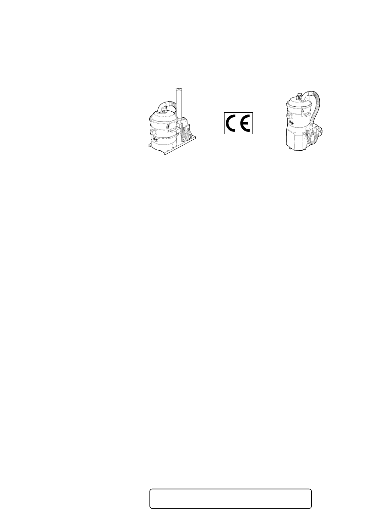
La macchina è stata realizzata nel rispetto della
Direttiva Macchine 89/392/CEE ed il simbolo CE
è riportato sull'aspiratore stesso.
Allegato al presente manuale:
- dichiarazione di conformità;
- certificato di garanzia.
1.2 - Personale addetto al funzionamento della macchina
The manufacturer therefore reserves the right
to update the production range and relative manuals without being obliged to update previous
machines and manuals unless in exceptional
cases.
Consult your nearest After-Sales Service Center
or CFM in case of doubt.
Note that the manufacturer continually strives to
optimize the product.
For this reason, the manufacturer is always more
than happy to receive all indications or proposals
able to improve either the machine or the manual.
The vacuum has been built in compliance with
Machines Directive 89/392/EEC and the CE symbol is affixed to the machine itself.
Enclosed with this manual:
- declaration of conformity;
- certificate of guarantee.
1.2 -
Machine operators
Il personale addetto deve essere un'operatore
del settore, opportunamente addestrato che deve
aver letto e compreso le istruzioni descritte nel
presente manuale.
Il datore di lavoro dovrà provvedere ad istruire il
personale sui rischi da infortuni, dei dispositivi e
indumenti predisposti per la sicurezza dell'operatore, sui rischi da emissioni da rumore e sulle
disposizioni generali previste dalle Direttive Europee e dalla legislazione del paese di installazione della macchina.
Con il termine “conduttore”, si intende la persona
che svolge le seguenti mansioni:
- compie le funzione necessarie al funziona-
mento della macchina.
- Opera sui comandi di funzionamento della
macchina.
- Compie semplici interventi legati al funziona-
mento (es.: scarico del materiale aspirato).
- Eventuali operazioni di pulizia e ispezione gior-
naliera.
ATTENZIONE!!
Machine operators must be persons working in
the sector who have been specially trained for
the purpose and who have read and understood
the instructions described in this manual.
The employer shall inform the personnel about
risks of accidents, the devices and garments
required for the safety of the operator, risks from
excessive noise levels and about the general
provisions established by the European Directives and legislation of the country where the
machine is installed.
The term “machine operator” means the person
that carries out the following tasks:
- accomplishment of operations required in order
to run the machine.
- Operation of the machine controls.
- Accomplishment of simple operations relating
to machine operation (eg.: emptying out the
vacuumed material).
- Accomplishment of cleaning operations and
daily inspections.
ATTENTION!!
Il conduttore deve operare esclusivamente
con i carter di protezione montati e le protezioni di sicurezza abilitate.
The machine operator must only work with
the protective casings mounted and the safety
devices enabled.
-2-
Page 8
3051 - 3101 - 3151 - 040/22 - 100/28 - 150/36
© C.F.M. S.p.A.
Tutti i diritti riservati
All rights reserved
- Manutentore meccanico:
opera in tutte le condizioni di funzionamento e
a tutti i livelli di protezione.
Effettua ogni riparazione o regolazione meccanica, ma non opera sugli impianti elettrici sotto
tensione.
- Manutentore elettrico:
opera in tutte le condizioni di funzionamento e
a tutti i livelli di protezione.
Effettua ogni intervento di riparazione e regolazione degli impianti elettrici, anche in presenza
di tensione.
Nota
Le competenze del personale addetto non sono
rigide, poichè l'operatore potrebbe avere conoscenze tali da comprendere più di una competenza.
- Mechanical servicing technician:
works in all operating conditions and at all
protection levels.
Carries out all mechanical repairs or adjustments, but does not work on powered electrical
systems.
- Servicing electrician:
operates in all operating conditions and at all
protection levels.
Carries out all repairs and adjustments to the
electrical system, even when this is powered.
Note
The tasks carried out by the relative personnel
are not rigidly defined since the operator may
possess know-how enabling him to carry out
more than one job.
- Tecnico del costruttore:
svolge attività di installazione, messa a punto,
modifica in accordo con il costruttore. Può
svolgere funzioni di addestramento.
1.3 - Simboli utilizzati nel presente
manuale
ATTENZIONE!!
Questa simbologia verrà utilizzata per richiamare l’attenzione su operazioni o punti pericolosi
che potrebbero provocare lesioni personali fino
anche la morte dell’operatore oppure che potrebbero danneggiare la macchina anche in modo
irreparabile.
- Manufacturer’s technician:
carries out installation, setting up and modification work in accordance with the manufacturer.
May also train other persons.
1.3 - Symbols used in this manual
ATTENTION!!
This symbol is used to call your attention to
dangerous operations or machine parts as could
cause personal injuries or even the death of the
operator, or as could cause even irreparable
damage to the machine.
Nota
Indica procedure o indicazioni importanti.
Note
Indicates important procedures or instructions.
-3-
Page 9

3051 - 3101 - 3151 - 040/22 - 100/28 - 150/36
© C.F.M. S.p.A.
Tutti i diritti riservati
All rights reserved
ATTENZIONE!!
Alcune illustrazioni contenute in questo li-
bretto per motivi di chiarezza raffigurano la
macchina o parti di essa con pannelli o carters
rimossi.
Non utilizzare mai la macchina priva di tali
protezioni.
1.4 - Collaudo e garanzia
1.4.1 - Collaudo
Per garantire il buon funzionamento dell’aspiratore in ogni sua parte, la macchina è stata collaudata presso i nostri stabilimenti.
Durante tale collaudo vengono effettuate prove
sui valori di aspirazione e prove di sicurezza sulle
parti elettriche.
Questo per garantire l’ottimizzazione dell’aspiratore rispetto all’impiego che sarà chiamato
ad assolvere.
ATTENTION!!
For explanatory purposes, some of the
illustrations in this manual depict the machine or machine parts with their panels or
casings removed.
Never ever use the machine without these
protections.
1.4 - Testing and guarantee
1.4.1 - Testing
The machine will have been tested in our plant
in order to ensure that it operates correctly.
Tests on the suction values are carried out
during this phase, while the electrical parts are
subjected to safety tests.
This ensures that the vacuum has been optimized
according to the job for which it was designed.
1.4.2 - Garanzia
Le clausole della garanzia sono specificate nel
contratto di vendita.
1.5 - Istruzioni per le richieste d'intervento
In caso di anomalie di funzionamento, di guasti
per i quali è necessario l'intervento del “Tecnico
del Costruttore” rivolgersi direttamente al servizio Assistenza tecnica del Costruttore.
1.6 - Esclusione di responsabilità
La macchina è stata consegnata all’utente alle
condizioni valide al momento dell’acquisto.
Per nessun motivo l’utente è autorizzato alla
manomissione della macchina. Ad ogni anomalia riscontrata rivolgersi al più vicino centro di
assistenza.
1.4.2 - Guarantee
The guarantee clauses are specified in the sales
contract.
1.5 - How to request assistance
Contact the Manufacturer’s technical Assistance
Service in the case of operational faults and
breakdowns where the intervention of the “Manufacturer’s Technician” is required.
1.6 - Exclusion of liability
The machine was delivered to the user according
to the conditions that were valid at the time of
purchase.
For no reason shall the user be authorized to
tamper with the machine. Contact your nearest
After-Sales Service Center in the event of faults.
-4-
Page 10

3051 - 3101 - 3151 - 040/22 - 100/28 - 150/36
© C.F.M. S.p.A.
Tutti i diritti riservati
All rights reserved
Ogni tentativo di smontaggio di modifica o in
generale di manomissione di un qualsiasi componente dell’aspiratore da parte dell’utente o da
personale non autorizzato ne invaliderà la garanzia e solleverà la ditta costruttrice da ogni responsabilità circa gli eventuali danni sia a persone che a cose derivanti da tale manomissione.
Il fabbricante si ritiene altresì sollevato da eventuali responsabilità nei seguenti casi:
- non corretta installazione;
- uso improprio della macchina da parte di per-
sonale non addestrato adeguatamente;
- uso contrario alle normative vigenti nel paese
di utilizzo;
- mancata o scorretta manutenzione prevista;
- utilizzo di ricambi non originali o non specifici
per il modello;
- inosservanza totale o parziale delle istruzioni;
- non invio del certificato di garanzia;
- eventi ambientali eccezionali.
All attempts by the user or by unauthorized
personnel to demount, modify or, more generally, tamper with any part of the vacuum shall void
the guarantee and relieve the manufacturer of all
responsibility for damage to either persons or
property caused by such action.
The manufacturer shall also be relieved of liability in the following cases:
- incorrect installation;
- improper use of the machine by inadequately
trained personnel;
- utilization contrary to the provisions in force in
the country of use;
- incorrect or insufficient maintenance;
- use of spurious spares or use of spares that are
not specifically made for the model in question;
- total or partial failure to comply with the instructions;
- failure to forward the guarantee certificate;
- exceptional environmental events.
1.7 - Limitazioni alla riproduzione e
divulgazione del manuale
Le informazioni tecniche contenute in questo
manuale sono di proprietà della CFM e devono
essere considerate di natura riservata. E’ pertanto vietata la divulgazione e la riproduzione
anche parziale senza l’autorizzazione scritta
del costruttore.
Inoltre è vietato utilizzare il presente manuale
per scopi diversi dalla installazione, dall’uso e
dalla manutenzione della macchina.
Ogni violazione sarà perseguita a termini di
legge.
1.7 - Limitations to duplication and disclosure of the manual contents
The technical information in this manual is the
property of CFM and shall be considered of a
confidential nature. It is therefore forbidden to
even partially duplicate or disclose such information without having received prior written authorization from the manufacturer.
It is also forbidden to use this manual for purposes other than machine installation, use and
maintenance.
All violations shall be prosecuted.
-5-
Page 11

3051 - 3101 - 3151 - 040/22 - 100/28 - 150/36
© C.F.M. S.p.A.
Tutti i diritti riservati
All rights reserved
-6-
Page 12
3051 - 3101 - 3151 - 040/22 - 100/28 - 150/36
© C.F.M. S.p.A.
Tutti i diritti riservati
All rights reserved
2
Descrizioni generali
General descriptions
2.1- Dati anagrafici del Costruttore
C.F.M. S.p.A
Via Porrettana, 1991
41059 Zocca (MO) Italy
Tel. 059/987802 - Fax 059/986253
Telex 522231 CFMASP I
2.1- Manufacturer's identification
data
2.2 - Dati di identificazione
Ogni volta che si contatta il “Servizio di assistenza tecnica” della CFM precisare sempre gli estre-
mi della macchina in Vostro possesso.
Una esatta indicazione del “Modello della macchina” e del “Numero di matricola” agevolerà le
risposte da parte del costruttore impedendo
inesattezze o errori.
Come promemoria suggeriamo di riportare i dati
della Vostra macchina nel seguente riquadro:
Macchina modello .......................................
N° di matricola.............................................
Anno di costruzione.....................................
Categoria.....................................................
Tensione di alimentazione...........................
2.2 - Identification data
Always state the identification data of the machine in your possession whenever you contact
the CFM “Technical After-Sales Service”.
An exact indication of the “Machine model” and
“Serial number” will facilitate the manufacturer
and prevent inexact or incorrect information from
being given.
As a memo, we suggest you write the data of your
machine in the following table:
Machine model............................................
Serial number..............................................
Year of manufacture....................................
Category......................................................
Powering voltage.........................................
-7-
Page 13
3051 - 3101 - 3151 - 040/22 - 100/28 - 150/36
© C.F.M. S.p.A.
Tutti i diritti riservati
All rights reserved
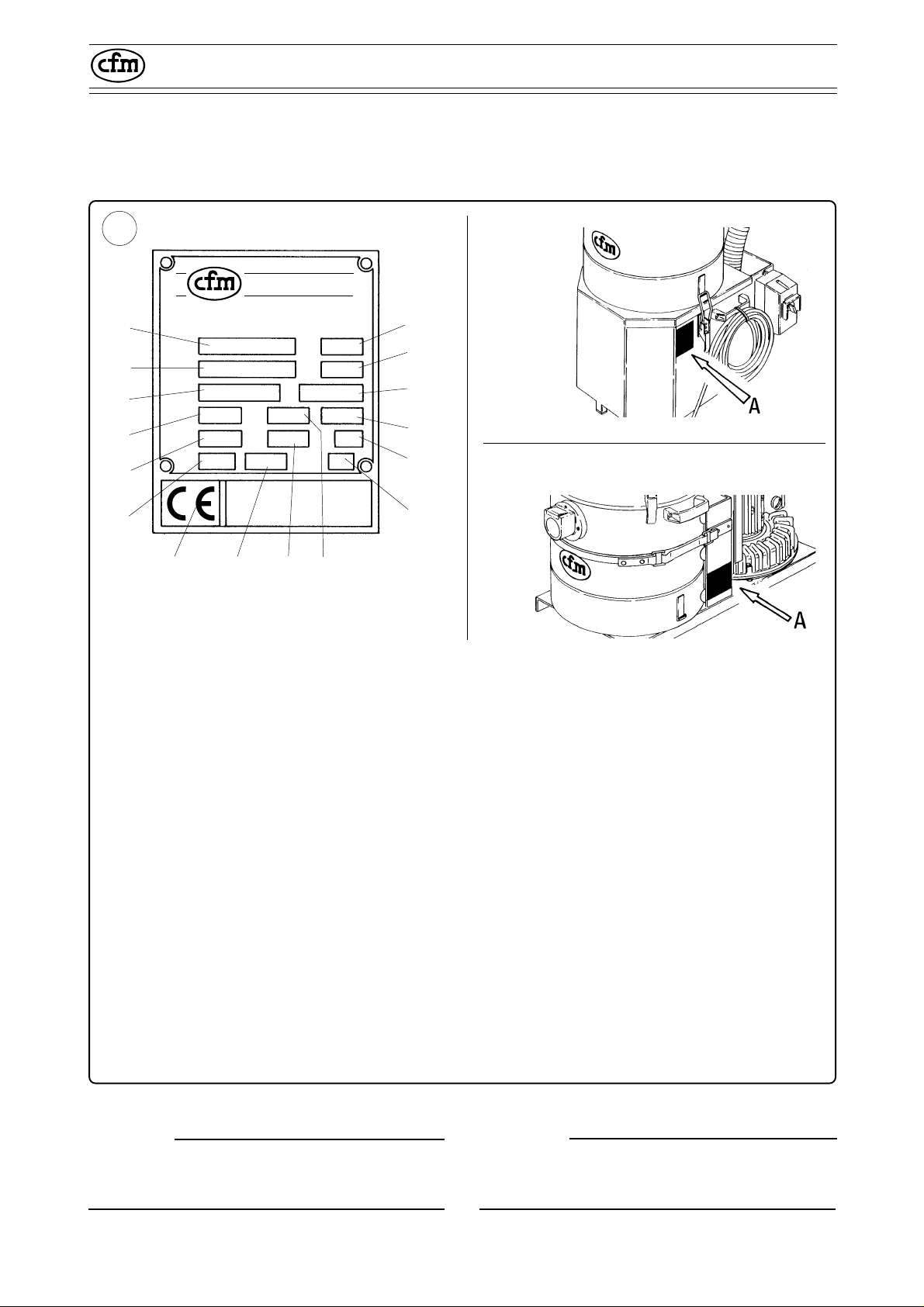
La targa di identificazione riportante i dati della
macchina è rappresentata in fig. 2.2.1.
A
Aspiratori Industriali
Trasportori Polveri
A
C
E
G
L
P
T
R
MH
B
D
F
I
N
S
A03
The identification plate with the machine data is
represented in fig. 2.2.1.
305102
3051 - 3101
3151
040/22 - 100/28
150/36
305138
A = Modello dell’aspiratore
B = Potenza installata
C = Numero di matricola
D = Frequenza di funzionamento
E = Categoria di appartenenza
F = Numero di giri al minuto del motore
G = Tensione di alimentazione con collegamento a
triangolo (volt)
H = Corrente con collegamento a triangolo (amper)
I = Alimentazione a tre fasi
L = Tensione di alimentazione con collegamento a
stella (volt)
M= Corrente con collegamento a stella (amper)
N = Grado di protezione del motore elettrico
P = Peso della macchina
R = Anno di costruzione
S = Classe di isolamento del motore elettrico
T = Macchina realizzata nel rispetto della Direttiva
macchine 89/392/CEE
A = Vacuum model
B = Electrical power
C = Serial number
D = Operating frequency
E = Category
F = Motor rpm
G = Powering voltage with delta connection
(Volts)
H = Current rating with delta connection (Amps)
I = Threephase power supply
L = Powering voltage with star connection
(Volts)
M = Current rating with star connection (Amps)
N = Protection degree of electric motor
P = Weight of the machine
R = Year of manufacture
S = Insulation class of electric motor
T = Machine built in compliance with Machine
Directive 89/392/EEC
Fig. 2.2.1
Nota
Per nessuna ragione i dati riportati sulla targhetta
possono essere alterati.
Note
For no reason must the data plate values be altered.
-8-
Page 14
3051 - 3101 - 3151 - 040/22 - 100/28 - 150/36
© C.F.M. S.p.A.
Tutti i diritti riservati
All rights reserved
2.3 - Parti principali
Per meglio comprendere la terminologia utilizzata nel presente manuale, si richiamano le
parti principali.
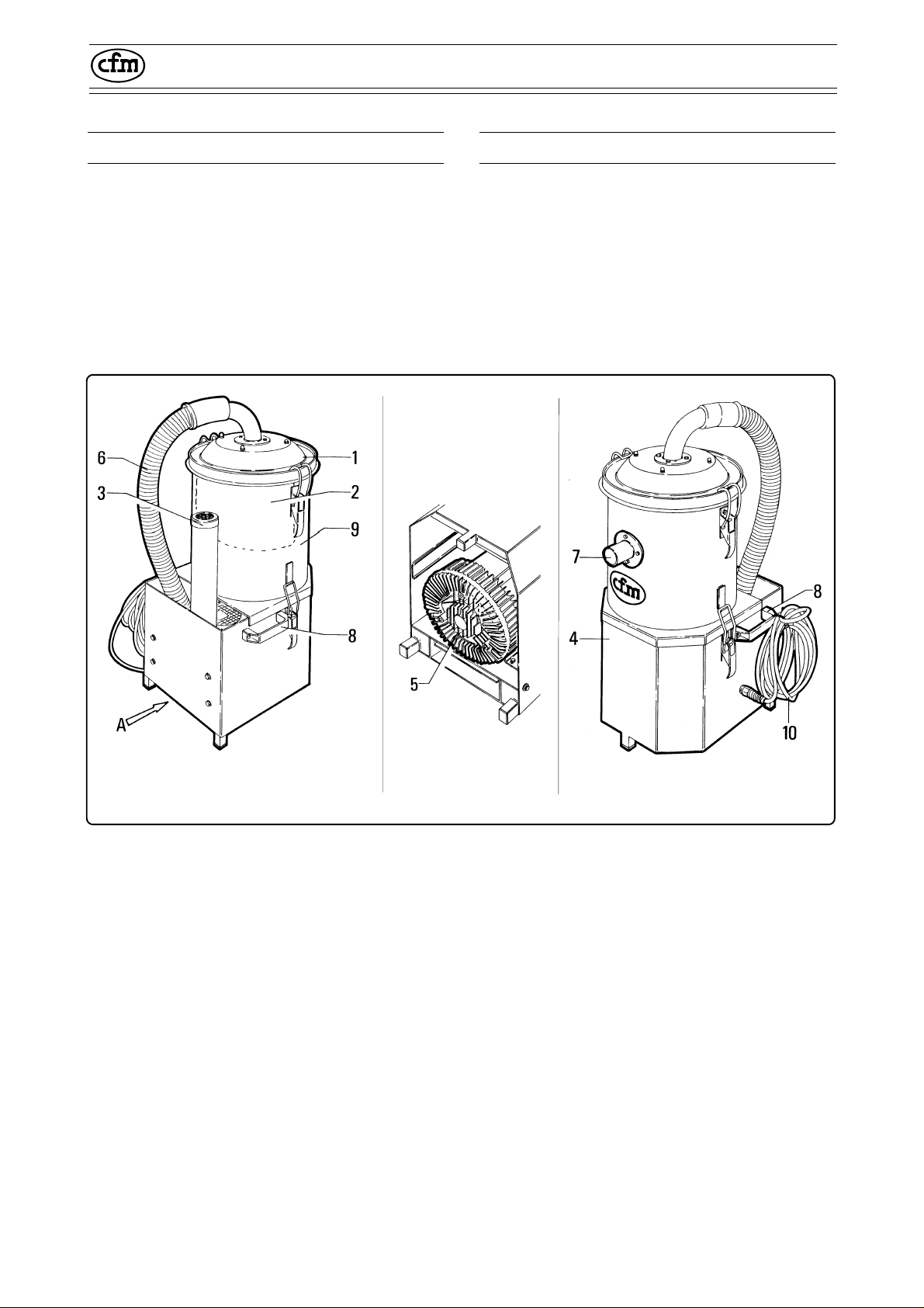
2.3.1 - Parti principali mod. 3051 - 3101
2.3 - Main parts
The following list of main parts will help
users to understand the terms used in this manual.
2.3.1 - Main parts mod. 3051 - 3101
305105
305103
1 - Coperchio del gruppo filtro
2 - Filtro primario
3 - Silenziatore di scarico aria filtrata (solo nel
modello 3101)
4 - Telaio
5 - Motore elettrico di aspirazione
6 - Tubo di collegamento
7 - Bocchettone di aspirazione per l'attacco
degli accessori
8 - Maniglie per il trasporto dell'aspiratore
9 - Camera filtrante e contenitore detriti aspira-
ti
10 - Cavo elettrico
305104
Fig. 2.3.1
1 - Filter unit cover
2 - Primary filter
3 - Filtered air exhaust silencer (only in the
model 3101)
4 - Frame
5 - Electric motor for vacuuming action
6 - Connecting tube
7 - Suction mouth to connect the accessories
8 - Handle to carry the vacuum cleaner
9 - Filtering chamber and vacuumed waste
container
10 - Electric cable
-9-
Page 15
3051 - 3101 - 3151 - 040/22 - 100/28 - 150/36
© C.F.M. S.p.A.
Tutti i diritti riservati
All rights reserved
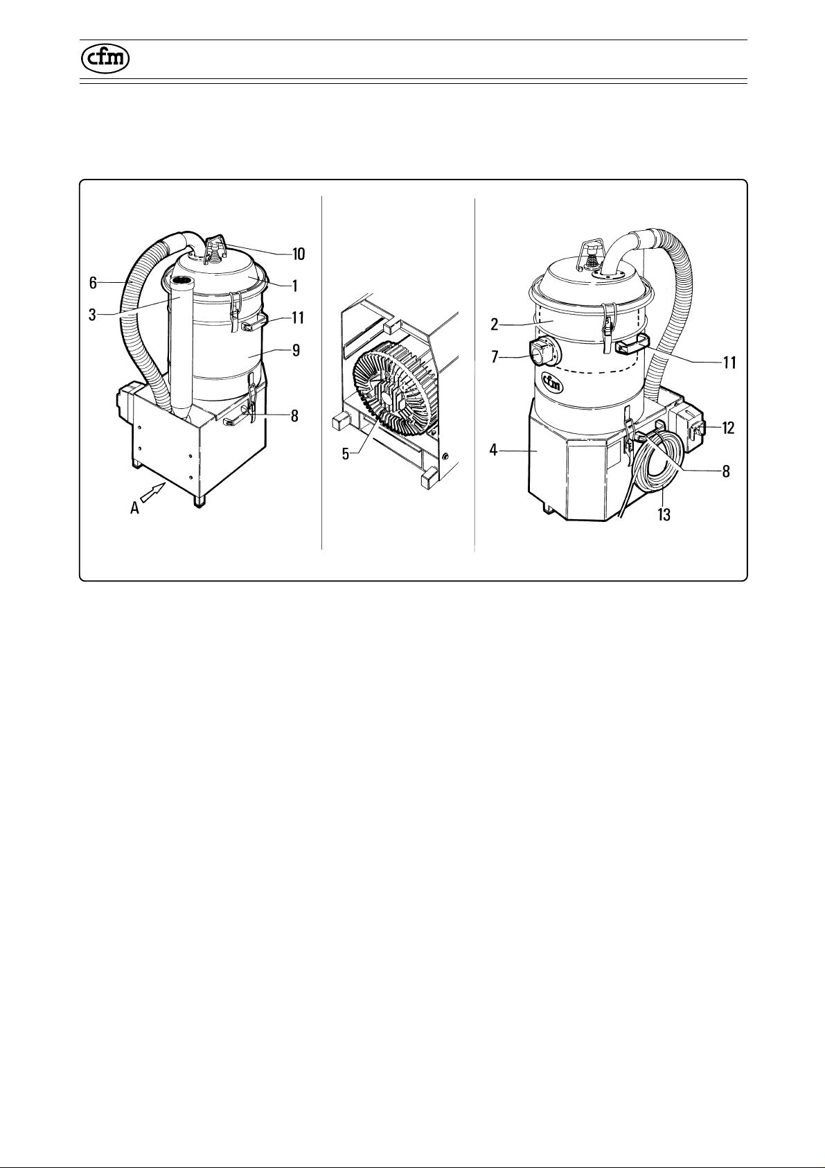
2.3.2 - Parti principali mod. 3151
2.3.2 - Main parts mod. 3151
305105
305106
1 - Cappello o coperchio del gruppo filtro
2 - Filtro primario
3 - Silenziatore di scarico aria filtrata
4 - Telaio
5 - Motore elettrico di aspirazione
6 - Tubo di collegamento
7 - Bocchettone di aspirazione per l'attacco
degli accessori
8 - Maniglie per il trasporto dell'aspiratore
9 - Camera filtrante e contenitore detriti aspira-
ti
10 - Pomello di scuotimento filtro
11 - Maniglie di sollevamento camera filtrante
12 - Quadro comandi (solo versione T)
13 - Cavo elettrico
305107
Fig. 2.3.2
1 - Cap or cover of the filter unit
2 - Primary filter
3 - Filtered air exhaust silencer
4 - Frame
5 - Electric suction motor
6 - Connecting pipe
7 - Suction mouth to connect the accessories
8 - Handle to carry the vacuum cleaner
9 - Filtering chamber and vacuumed waste
container
10 - Filter shaking knob
11 - Handles to lift the filtering chamber
12 - Control panel (version T only)
13 - Electric cable
-10-
Page 16
3051 - 3101 - 3151 - 040/22 - 100/28 - 150/36
© C.F.M. S.p.A.
Tutti i diritti riservati
All rights reserved
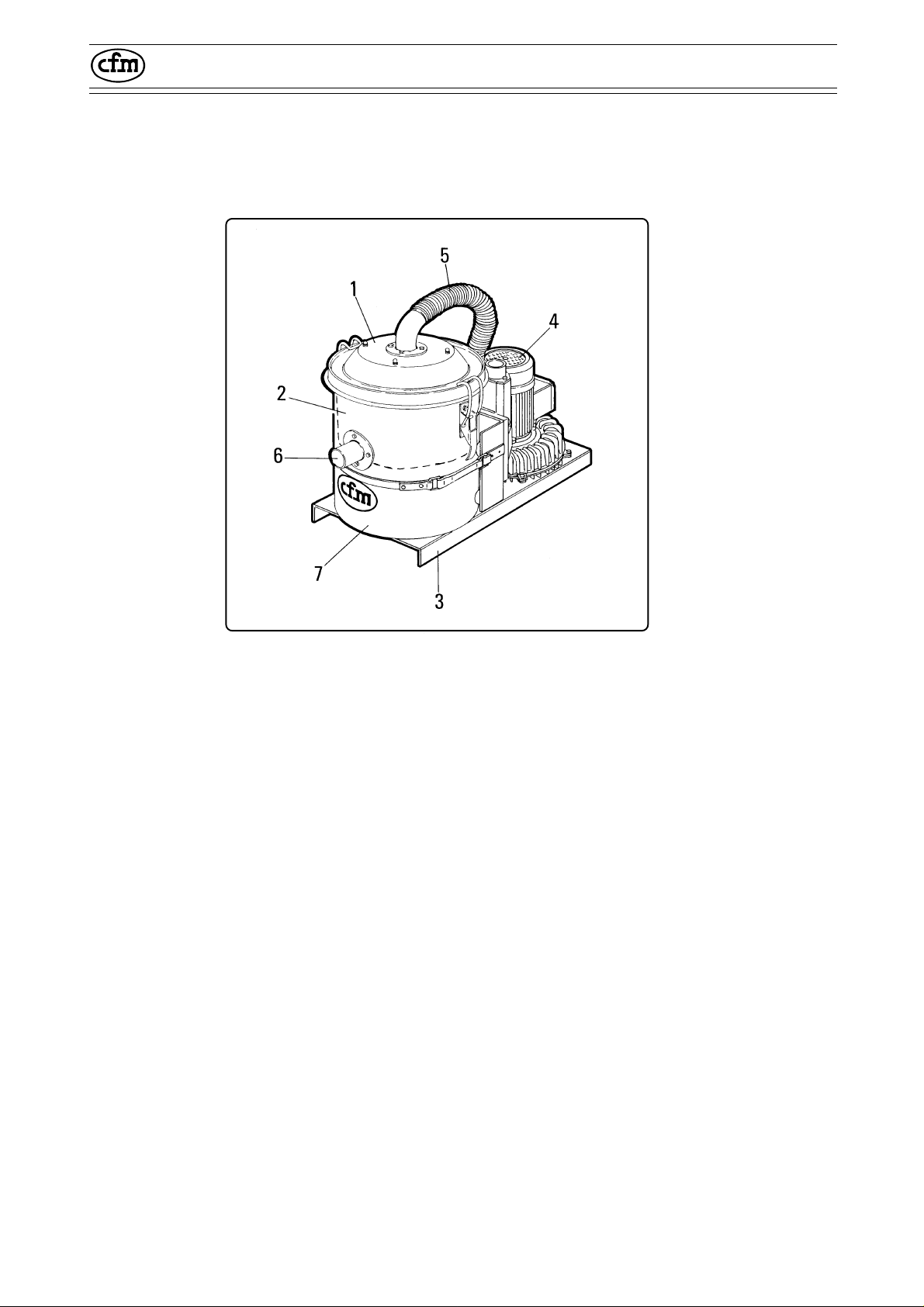
2.3.3 - Parti principali mod. 040/22
100/28
2.3.2 - Main parts mod. 040/22
100/28
1 - Cappello o coperchio del gruppo filtro
2 - Filtro primario
3 - Telaio
4 - Motore elettrico di aspirazione
5 - Tubo di collegamento
6 - Bocchettone di aspirazione per l'attacco
degli accessori
7 - Camera filtrante e contenitore detriti aspira-
ti
305159
Fig. 2.3.3
1 - Cap or cover of the filter unit
2 - Primary filter
3 - Frame
4 - Electric suction motor
5 - Connecting pipe
6 - Suction mouth to connect the accessories
7 - Filtering chamber and vacuumed waste
container
-11-
Page 17
3051 - 3101 - 3151 - 040/22 - 100/28 - 150/36
© C.F.M. S.p.A.
Tutti i diritti riservati
All rights reserved
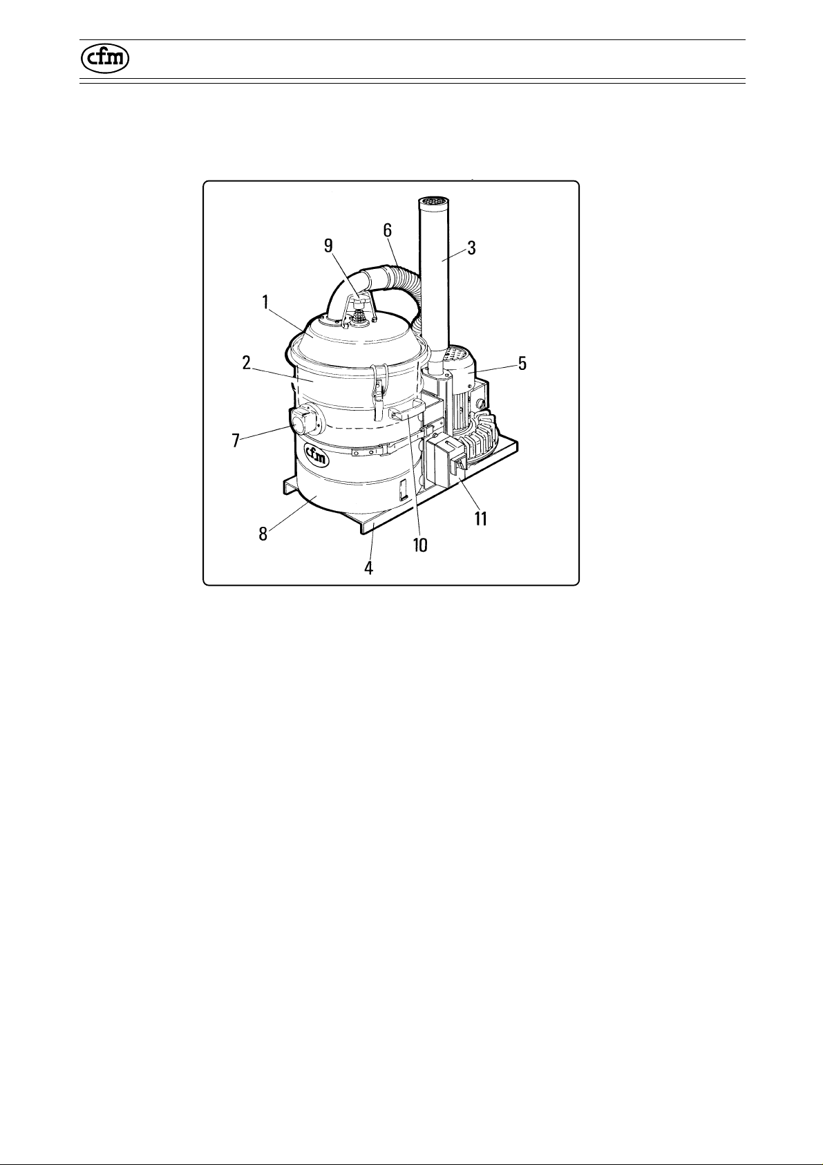
2.3.4 - Parti principali mod. 150/36
2.3.4 - Main parts mod. 150/36
1 - Cappello o coperchio del gruppo filtro
2 - Filtro primario
3 - Silenziatore di scarico aria filtrata
4 - Telaio
5 - Motore elettrico di aspirazione
6 - Tubo di collegamento
7 - Bocchettone di aspirazione per l'attacco
degli accessori
8 - Camera filtrante e contenitore detriti aspira-
ti
9 - Pomello di scuotimento filtro
10 - Maniglie di sollevamento camera filtrante
11 - Quadro comandi (solo versione T)
305139
Fig. 2.3.4
1 - Cap or cover of the filter unit
2 - Primary filter
3 - Filtered air exhaust silencer
4 - Frame
5 - Electric suction motor
6 - Connecting pipe
7 - Suction mouth to connect the accessories
8 - Filtering chamber and vacuumed waste
container
9 - Filter shaking knob
10 - Handles to lift the filtering chamber
11 - Control panel (version T only)
-12-
Page 18
3051 - 3101 - 3151 - 040/22 - 100/28 - 150/36
© C.F.M. S.p.A.
Tutti i diritti riservati
All rights reserved
2.4 - Descrizione della macchina
La macchina in Vostro possesso è stata progettata per l’aspirazione di polveri e detriti vari.
E’ una macchina progettata e costruita per operare in ambienti industriali dove può operare per
24 ore al giorno oppure, saltuariamente, per
normali pulizie.
Il materiale aspirato è sottoposto ad una azione
centrifugata all’interno del contenitore dove i
corpi più grossolani vengono raccolti per effetto
del loro peso, mentre l’aria passa attraverso una
adeguata superficie filtrante dove i corpi in sospensione vengono trattenuti.
La CFM, a richiesta, è in grado di allestire macchine idonee per operare con sostanze corrosive, di operare in ambienti ad alto rischio di
esplosione, di realizzare versione a filtro assoluto e così via.
L’elevata qualità dell’aspiratore in Vostro possesso è garantita da severissimi tests. Materiali
e componenti vengono infatti sottoposti durante
le diverse fasi della produzione, ad una serie di
rigorose verifiche per accettarne l’appartenenza
agli elevati standard qualitativi fissati.
2.4 - Description of the machine
The machine in your possession has been designed to suck up dust and various waste materials.
The vacuum has been designed and built to
operate in industrial environments where it can
work round the clock or at intervals, for normal
cleaning purposes.
The exhausted material is subjected to a centrifugal action inside the container where the
coarser items are collected owing to their weight.
The air passes through a filtering surface where
solids in suspension are retained.
On request, CFM can supply machines able
to work with corrosive substances, fit to work in
environments with a high risk of explosion, versions with absolute filters and so forth.
The high quality of the vacuum in your possession is guaranteed by the strictest tests. Materials and components are subjected to a series of
strict inspections during the various production
phases in order to ascertain compliance with the
established high qualitative standards.
ATTENZIONE!!
Per nessun motivo l’apparecchiatura deve
essere manomessa dall’utente.
Ogni tentativo di smontaggio, di modifica o
manomissione di qualsiasi parte della macchina ne invaliderà la garanzia e solleverà la
ditta costruttrice da ogni responsabilità sugli
eventuali danni sia a persone che a cose
derivanti da tale manomissione.
Per ogni anomalia riscontrata, rivolgersi al
centro di assistenza autorizzato più vicino.
ATTENTION!!
For no reason must the user tamper with the
equipment.
All attempts by the user or by unauthorized
personnel to demount, modify or, more generally, tamper with any part of the exhauster
shall void the guarantee and relieve the
manufacturer of all responsibility for damage
to either persons or property caused by such
action.Contact your nearest After-Sales
Service Center in the event of faults.
-13-
Page 19
3051 - 3101 - 3151 - 040/22 - 100/28 - 150/36
© C.F.M. S.p.A.
Tutti i diritti riservati
All rights reserved
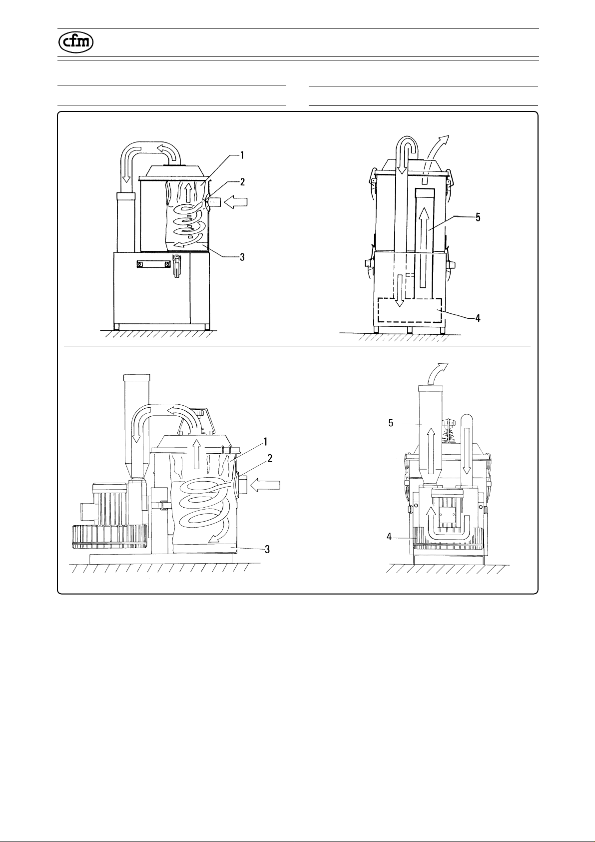
2.5 - Principio di funzionamento
Modelli 3051-3101-3151
Models 3051-3101-3151
Aria aspirata carica di detriti
Intaken air and waste
Modelli 040/22-100/28-150-36
Models 040/22-100/28-150-36
2.5 - Operating principle
Aria filtrata
Filtered air
305109305108
Aria filtrata
Filtered air
Aria aspirata carica di
detriti
Intaken air and waste
305140
Accendendo l’aspiratore, si crea una depressione alla bocca del tubo di aspirazione che procura
il risucchio del materiale da aspirare.
Il materiale aspirato, attraversa il tubo e gli accessori finali, quindi arriva nel contenitore “3”
dove un deflettore “2” presente nella camera
filtrante imprime al materiale un moto centrifugo
provocando la caduta delle particelle più pesanti
sul fondo del contenitore “3”.
L’aria aspirata, trascinando le particelle più leggere attraversa il filtro primario che le trattiene.
Infine l’aria filtrata entra nelle giranti “4” delle
unità aspirante, quindi viene espulsa dal silenziatore “5”.
305141
Fig. 2.5.1
When the vacuum is powered, suction is created
at the pipe inlet and this sucks in the waste material.
This waste material passes through the pipe and
final accessories until it reaches container “3”
where a baffle “2” in the filtering chamber subjects it to a centrifugal action causing the heavier
solids to drop to the bottom of container “3”.
The intaken air entrains the lighter particles
through primary filter where they are retained.
Lastly, the filtered air enters impellers “4” of the
suction unit from whence it is exhausted through
silencer “5”.
-14-
Page 20
3051 - 3101 - 3151 - 040/22 - 100/28 - 150/36
© C.F.M. S.p.A.
Tutti i diritti riservati
All rights reserved
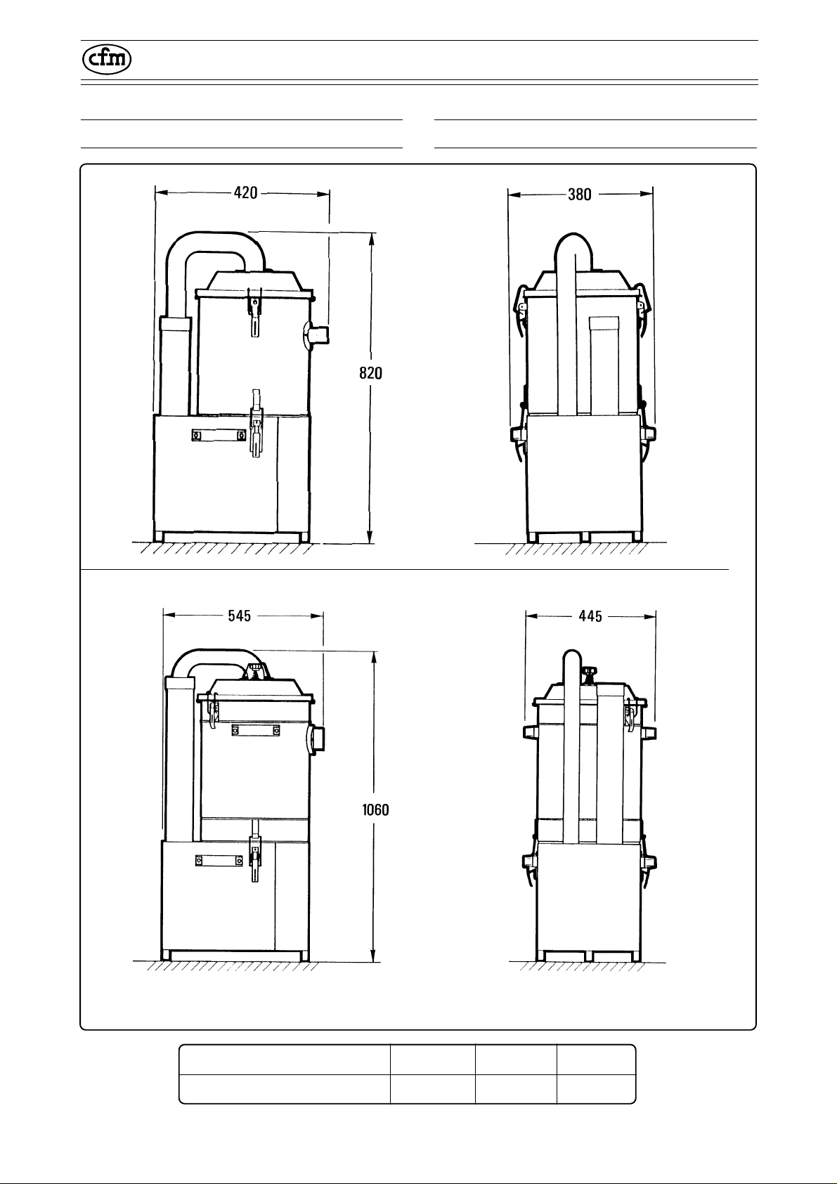
2.6 - Dimensioni di ingombro e pesi
305110
2.6 - Overall dimensions and weights
Mod. 3051 - 3101
305111
305112
Mod. 3151
305113
Nota: tutte le dimensioni sono espresse in mm.
Modello/Model 3051 3101 3151
Peso (kg)/Weight (kg) 24 28 42
Note: all dimensions are expressed in millimeters.
Fig. 2.6.1
-15-
Page 21
3051 - 3101 - 3151 - 040/22 - 100/28 - 150/36
© C.F.M. S.p.A.
Tutti i diritti riservati
All rights reserved
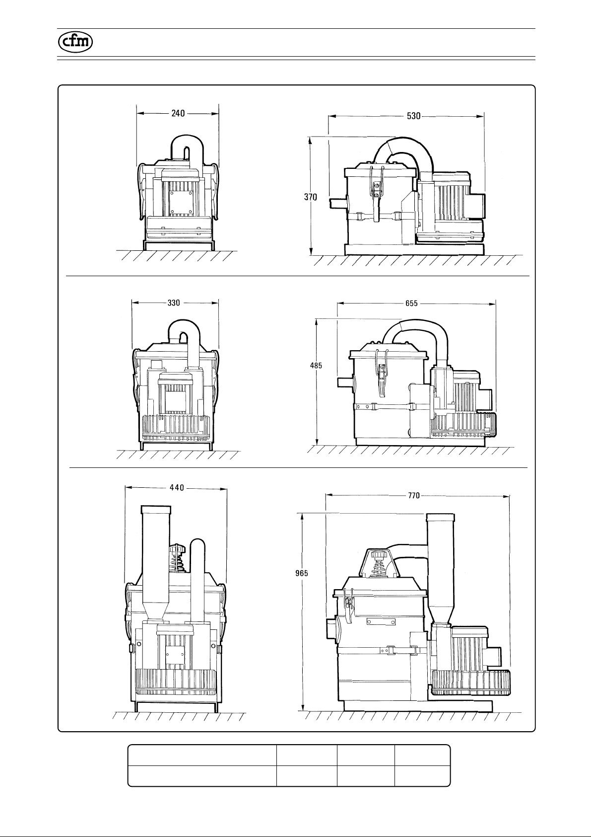
305142
305144
Mod. 040/22
Mod. 100/28
305143
305145
305146
Mod. 150/36
Modello/Model 040/22 100/28 150/36
305147
Fig. 2.6.1
Peso (kg)/Weight (kg) 17 22 39
-16-
Page 22

3051 - 3101 - 3151 - 040/22 - 100/28 - 150/36
© C.F.M. S.p.A.
Tutti i diritti riservati
All rights reserved
2.7 - Dati tecnici
Unità
Parametro di misura
2.7 - Technical datas
3051 3101 3151
Tensione Volts 230/400 230/400 230/400
Frequenza Hz 50 50 50
Potenza kW 0,36 0,73 1,5
Potenza HP 0,5 1 2
Depressione max mm H20 1200 2050 2500
Portata d’aria max lt/m' 1300 2600 3850
Superficie filtro cm
2
2300 2300 4200
Rumorosità dB 61 63 67
Protezione IP 55 55 55
Isolamento classe F F F
Capienza lt 9 9 25
Aspirazione mm Ø 40 40 50
Peso kg 24 28 42
Descriptions
Unit of measurement
3051 3101 3151
Voltage Volts 230/400 230/400 230/400
Frequency Hz 50 50 50
Rating Kw 0,36 0,73 1,5
Rating HP 0,5 1 2
Max. vacuum mm H20 1200 2050 2500
Max. air flow rate l/min 1300 2600 3850
Filter area cm
2
2300 2300 4200
Noise rating dB 61 63 67
Protection IP 55 55 55
Insulation class BF F F
Capacity l 9 9 25
Inlet Ø mm 40 40 50
Weight kg 24 28 42
-17-
Page 23

3051 - 3101 - 3151 - 040/22 - 100/28 - 150/36
© C.F.M. S.p.A.
Tutti i diritti riservati
All rights reserved
Unità
Parametro di misura
040/22 100/28 150/36
Tensione Volts 230/400 230/400 230/400
Frequenza Hz 50 50 50
Potenza kW 0,36 0,73 1,5
Potenza HP 0,5 1 2
Depressione max mm H20 1200 2050 2500
Portata d’aria max lt/m' 1300 2600 3850
Superficie filtro cm
2
2300 2300 4200
Rumorosità dB 61 65 68
Protezione IP 55 55 55
Isolamento classe F F F
Capienza lt 9 9 25
Aspirazione mm Ø 40 40 50
Peso kg 17 22 39
Descriptions
Unit of measurement
040/22 100/28 150/36
Voltage Volts 230/400 230/400 230/400
Frequency Hz 50 50 50
Rating Kw 0,36 0,73 1,5
Rating HP 0,5 1 2
Max. vacuum mm H20 1200 2050 2500
Max. air flow rate l/min 1300 2600 3850
Filter area cm
2
2300 2300 4200
Noise rating dB 61 65 68
Protection IP 55 55 55
Insulation class BF F F
Capacity l 9 9 25
Inlet Ø mm 40 40 50
Weight kg 17 22 39
-18-
Page 24

3051 - 3101 - 3151 - 040/22 - 100/28 - 150/36
© C.F.M. S.p.A.
Tutti i diritti riservati
All rights reserved
2.8 - Uso previsto
2.8.1 - Condizioni ambientali di utilizzo
Salvo diversa precisazione all'ordine si intende
che l'aspiratore è previsto per funzionare nelle
seguenti condizioni ambientali:
- altitudine: non superiore a 800 mt;
- temperatura ambiente: minima: -5 °C;
massima: +40 °C;
- umidità relativa: non superiore al 50% a 40 °C.
2.8.2 - Illuminazione
L'impianto luce dello stabilimento è da ritenersi
importante per la sicurezza delle persone e della
qualità del lavoro.
Il luogo di installazione della macchina deve
garantire, con illuminazione naturale o artificiale,
una buona visibilità in ogni punto della macchina.
Deve garantire una chiara lettura delle targhe di
avvertenza e di pericolo collocate sulla macchina
e l'individuazione dei pulsanti di comando e degli
indicatori di controllo.
L'illuminazione non deve creare effetti stroboscopici.
2.8 - Proper use
2.8.1 - Environmental conditions of use
Unless established differently on order, the
vacuum cleaner is designed to operate in the
following environmental conditions:
- altitude: not more than 800 m.;
- ambient temperature: minimum: -5
maximum: +40 °C;
- relative humidity: not more than 50% at 40
2.8.2 - Lighting
The lighting system in the factory is important for
the safety of the personnel and quality of the
work.
The place in which the machine is installed must,
with natural or artificial lighting, guarantee good
visibility in all points of the machine. It must
ensure that the warnings and danger signs affixed to the machine can be clearly read and that
the control buttons and monitoring indicators can
be identified.
The lighting must not create stroboscopic effects.
°
C;
°
C.
2.8.3 - Atmosfera con rischio di esplosione e/o incendio
La macchina standard non è predisposta per
l'utilizzo in ambienti con atmosfera esplosiva e/o
a rischio d'incendio.
Il cliente/utente deve specificare sull'ordine se
l'aspiratore deve operare in ambienti con atmosfera esplosiva e/o a rischio d'incendio.
Solamente la versione "DEX" può aspirare in
ambienti con rischio di esplosione o di incendio.
ATTENZIONE!!
Condizioni ambientali diverse da quelle pre-
scritte possono causare inconvenienti meccanici od elettrici con conseguenti situazioni
di pericolo per il conduttore.
2.8.3 - Places where there is a risk of
explosion and/or fire outbreak
The standard machine is not designed for use in
places with an explosive atmosphere or where
there is a risk of explosion.
When ordering, the customer/user must indicate
whether the vacuum cleaner must work in places
with an explosive atmosphere or where there is
a risk of explosion.
Only the “DEX” version may be used to vacuum
in places where there is a risk of fire or explosion.
ATTENTION!!
Environmental conditions differing from those
prescribed may lead to mechanical or electrical faults and consequent situations of hazard
for the operator.
-19-
Page 25

3051 - 3101 - 3151 - 040/22 - 100/28 - 150/36
© C.F.M. S.p.A.
Tutti i diritti riservati
All rights reserved
2.9 - Rumore aereo
Il livello di pressione acustica è inferiore a 70
db(A).
Il datore di lavoro dovrà attuare, nell'ambiente di
lavoro, le misure tecniche adeguate per ridurre al
minimo i rischi derivanti dall'esposizione giornaliera al rumore.
2.10 - Vibrazioni
Le vibrazioni trasmesse dalla macchina non sono
significative.
2.9 - Noise level
The acoustic pressure level is less than 70 dB(A).
The employer must take all the necessary technical measures in the place of work in order to
reduce the risks deriving from daily exposure to
noise to the minimum.
2.10 - Vibrations
The vibrations transmitted by the machine are
not significant.
2.11 - Emissioni di gas o radiazioni
La macchina non emette gas o radiazioni nocive.
2.12 - Campi elettromagnetici
I campi elettromagnetici ad alta frequenza non
sono significativi.
2.11 - Gas or radiation emissions
The machine does not emit gas or harmful
radiations.
2.12 - Electromagnetic fields
The high frequency electromagnetic fields are
not significant.
-20-
Page 26

3051 - 3101 - 3151 - 040/22 - 100/28 - 150/36
© C.F.M. S.p.A.
Tutti i diritti riservati
All rights reserved
2.13 - Usi non consentiti
Di seguito si riportano alcuni impieghi della macchina RIGOROSAMENTE DA EVITARE!!
- Non aspirare liquidi di nessun genere.
- Non operare in ambienti saturi di gas esplosivi.
- Non aprire il contenitore di raccolta con macchina in funzione.
- Non aspirare mozziconi di sigarette accese. Si
potrebbe incendiare il filtro.
- In ambienti antideflagranti è assolutamente
vietato l’impiego di macchine in versione standard.
In tali situazioni richiedere motorizzazioni e
componenti elettrici adeguati.
Non utilizzare la macchina standard per aspirare
prodotti chimici, corrosivi poichè per tale utilizzo
occorre la versione “X”.
Non aspirare:
- sostanze radioattive;
- sostanze che unite possono creare incendio od
esplosione;
- sostanze la cui natura provoca il rischio di
contaminazione biologica o microbiologica;
- sostanze alimentari (fatta eccezione per la
versione “X”).
- Non utilizzare l’aspiratore su piani sconnessi o
inclinati con pendenza superiore al 5%.
- Non accedere ai componenti elettrici. Tale accesso è consentito solamente a personale specializzato che comunque deve aver disinserito
l’interruttore generale installato a monte dell'aspiratore o la spina dalla presa di corrente.
2.13 - Improper uses
The following is a list of machine uses that should
be STRICTLY AVOIDED!!
- Never vacuum liquids of any type.
- Never operate in environments saturated with
explosive gases.
- Never open the container whilst the machine is
operating.
- Never suck up lighted cigarette ends. This
could cause the filter to catch light.
- It is absolutely forbidden to use the standard
version of the machine in environments where
there is a risk of explosion.
Ask for adequate drive units and electrical
components in such situations.
Do not use the standard machine to vacuum
chemical or corrosive products since version “X”
is required for such use.
Do not use the machine to vacuum:
- radioactive substances;
- substances which, when combined, could create fire outbreaks or explosion;
- substances whose nature could lead to the risk
of biological or microbiological contamination;
- foodstuffs, unless version “X” is used.
- Never use the vacuum on irregular ground or
on slopes exceeding 5%.
- Never access the electrical components. Such
action may only be carried out by specialized
personnel and only after having disconnected
the main switch installed prior to the vacuum or
after having removed the plug from the current
socket.
-21-
Page 27

3051 - 3101 - 3151 - 040/22 - 100/28 - 150/36
© C.F.M. S.p.A.
Tutti i diritti riservati
All rights reserved
-22-
Page 28

3051 - 3101 - 3151 - 040/22 - 100/28 - 150/36
© C.F.M. S.p.A.
Tutti i diritti riservati
All rights reserved
3
Prescrizioni di sicurezza
Safety prescriptions
3.1 - Prescrizioni generali
Leggere attentamente questo manuale prima di
procedere all’avviamento, utilizzo, manutenzione ed ogni altro intervento sull’aspiratore.
Non consentire al personale non autorizzato di
intervenire sull’aspiratore.
Non indossare capi di vestiario slacciati o penzo-
lanti come cravatte, sciarpe, indumenti strappati
che possano impigliarsi o venire catturati dall’aspiratore.
3.1 - General prescriptions
Become thoroughly familiar with the contents of
this manual before starting, using, servicing or
operating on the vacuum in any way.
Never allow unauthorized personnel to work on
the vacuum.
Never wear unbuttoned or loose clothing
such as ties, scarves or torn garments as could
become caught up by the vacuum.
Usare capi appropriati ai fini antinfortunistici.
Consultare il datore di lavoro circa le prescrizioni
di sicurezza vigenti ed i dispositivi antinfortunistici specifici da adottare per la sicurezza personale.
Non avviare la macchina in avaria.
Prima di usare la macchina accertarsi che qual-
siasi condizione pericolosa per la sicurezza sia
stata opportunamente eliminata ed avvertire i
responsabili preposti di ogni eventuale irregolarità di funzionamento.
Accertarsi che tutti i ripari e le protezioni siano al
loro posto e che tutti i dispositivi di sicurezza
siano presenti ed efficienti.
L’area dove si effettuano le operazioni di manu-
tenzione (ordinaria e straordinaria) deve essere
sempre pulita, asciutta e con l’idonea attrezzatura sempre disponibile ed efficiente.
Qualsiasi intervento riparativo deve essere ese-
guito esclusivamente a macchina ferma, scollegata dall’alimentazione elettrica. Non eseguire
alcun intervento riparativo senza preventiva autorizzazione.
Wear appropriate clothing for accident-preven-
tion purposes.
Consult your employer about the current safety
provisions and specific accident-preventing devices to use in order to ensure personal safety.
Never start the machine if it is faulty.
Before using the machine, always check that
any hazardous condition has been eliminated
and inform the persons in charge about any
operational fault.
Check that all guards and protections are cor-
rectly mounted and that all safety devices are
installed and efficient.
The area where maintenance operations are
carried out (ordinary and extraordinary) must
always be clean and dry. Suitable tools must
always be available and efficient.
Repairs must only be carried out when the
machine is at a standstill and disconnected from
the electricity supply. Never ever carry out repairs without having first received the necessary
authorization.
-23-
Page 29

3051 - 3101 - 3151 - 040/22 - 100/28 - 150/36
© C.F.M. S.p.A.
Tutti i diritti riservati
All rights reserved
Rispettare le procedure e le informazioni qui
riportate per la manutenzione e l’assistenza tecnica.
Come detergenti non utilizzare mai benzina sol-
venti o altri liquidi infiammabili.
Al contrario utilizzare solventi commerciali auto-
rizzati ininfiammabili e non tossici.
Non utilizzare l’aria compressa per la pulizia
della macchina o particolari di essa. Quando
proprio inevitabile proteggersi con occhiali
aventi ripari laterali e limitare la pressione ad
un massimo di 2 bar.
Non lubrificare la macchina ne aprire il conteni-
tore di raccolta rifiuti con l’aspiratore in funzione.
Prima di iniziare il collegamento elettrico accer-
tarsi che la tensione e la frequenza di alimentazione siano quelle riportate sulla targa della
macchina.
Comply with the maintenance and technical as-
sistance procedures and information given in this
manual.
Never ever use gasoline, solvents or other in-
flammable liquids as detergents.
Only use commercially available authorized non-
inflammable and non-toxic solvents.
Never use compressed air to clean the machine
or its components. When this is absolutely unavoidable, protect the eyes by wearing goggles
with side guards and limit the pressure to 2 bar at
most.
Never lubricate the machine or open the waste
container whilst the vacuum is operating.
Before beginning the electrical connections,
check that the powering voltage and frequency
values are those indicated on the data plate of
the machine.
Effettuare il collegamento elettrico ad una rete
provvista di messa a terra efficiente.
Qualsiasi intervento sulla parte elettrica deve
essere eseguito esclusivamente da personale
autorizzato e comunque con macchina scollegata dalla rete elettrica di alimentazione.
Non spostare l’aspiratore trainandolo per il cavo
di alimentazione. Si danneggia l’aspiratore e si
rischia la folgorazione.
3.2 - Targhe di avvertenza (fig. 3.2.1)
ATTENZIONE!!
Rispettare le avvertenze delle targhe.
L’inosservanza può causare lesioni personali fino anche la morte.
Accertarsi che le targhe siano sempre presenti e leggibili. In caso contrario provvedere allo loro sostituzione.
Connect the machine to an electricity main with
an efficient ground circuit.
Only authorized personnel must be allowed to
work on the electrical part of the machine and this
must always be disconnected from the electricity
main.
Never move the vacuum by pulling the power
cable. This would damage the vacuum itself
while the operator could risk being electrocuted.
3.2 - Warning plates (fig. 3.2.1)
ATTENTION!!
Comply with the data plate warnings.
Failure to do this could cause personal
injuries and even death.
Check that the data plates are always affixed
and legible. Replace them if this is not the
case.
-24-
Page 30

3051 - 3101 - 3151 - 040/22 - 100/28 - 150/36
© C.F.M. S.p.A.
Tutti i diritti riservati
All rights reserved
Mod. 3051 - 3101
305114
Mod. 3151
305115
Mod. 3051T - 3101T - 3151T
B
A
A07
A - Targa di attenzione
Cod. targa: 817107
Richiama l’attenzione dell’operatore av-
vertendolo della necessità di scuotere il
filtro solamente con macchina spenta.
In caso contrario la manovra non produrrebbe alcun effetto rischiando di danneggiare il filtro stesso.
B - Targa di quadro sotto tensione
Cod. targa: 817089
Segnala la presenza all’interno del quadro
della tensione riportata sulla targhetta.
Per questo motivo l’accesso al quadro deve
essere consentito solamente a personale
espressamente autorizzato che comunque prima di accedere ai componenti elettrici deve sempre scollegare l’alimentazione alla macchina, disinserendo la spina
dalla presa corrente.
305115
B
400 VOLT
Fig. 3.2.1
A - Attention plate
Data plate code: 817107
Draws the operator’s attention to the fact
that the filter must only be shaken when the
machine is off.
Failing this, the manoeuvre would have no
effect while the filter itself could be damaged.
B - Panel power plate
Data plate code: 817089
Indicates that the panel is powered by the
voltage given on the data plate.
For this reason, only explicitly authorized
persons may be allowed access to the
electric panel and only after having disconnected the machine from the electricity
source by removing the plug from the
socket.
-25-
Page 31

3051 - 3101 - 3151 - 040/22 - 100/28 - 150/36
© C.F.M. S.p.A.
Tutti i diritti riservati
All rights reserved
Mod. 040/22 - 100/28 - 150/36
305148
Mod. 150/36
305149
305150
A
A07
A - Targa di attenzione
Cod. targa: 817107
Richiama l’attenzione dell’operatore av-
vertendolo della necessità di scuotere il
filtro solamente con macchina spenta.
In caso contrario la manovra non produrrebbe alcun effetto rischiando di danneggiare il filtro stesso.
B - Targa di quadro sotto tensione
Cod. targa: 817089
Segnala la presenza all’interno del quadro
della tensione riportata sulla targhetta.
Per questo motivo l’accesso al quadro deve
essere consentito solamente a personale
espressamente autorizzato che comunque prima di accedere ai componenti elettrici deve sempre scollegare l’alimentazione alla macchina, disinserendo la spina
dalla presa corrente.
B
400 VOLT
Fig. 3.2.2
A - Attention plate
Data plate code: 817107
Draws the operator’s attention to the fact
that the filter must only be shaken when the
machine is off.
Failing this, the manoeuvre would have no
effect while the filter itself could be damaged.
B - Panel power plate
Data plate code: 817089
Indicates that the panel is powered by the
voltage given on the data plate.
For this reason, only explicitly authorized
persons may be allowed access to the
electric panel and only after having disconnected the machine from the electricity
source by removing the plug from the
socket.
-26-
Page 32

3051 - 3101 - 3151 - 040/22 - 100/28 - 150/36
© C.F.M. S.p.A.
Tutti i diritti riservati
All rights reserved
3.3 - Dispositivi di sicurezza
ATTENZIONE!!
Prima della messa in funzione e dell’uso
della macchina, accertarsi del corretto posizionamento di tutte le protezioni e della loro
piena efficienza.
Le sicurezze non devono mai essere manomesse.
All’inizio di ogni turno di lavoro o del loro
impiego verificare la presenza e l’efficienza
delle protezioni e delle sicurezze. In caso
contrario spegnere l’aspiratore ed avvertire
il responsabile preposto.
3.3 - Safety devices
ATTENTION!!
Check that all guards are correctly positio-
ned and fully efficient before starting and
using the machine.
Never tamper with the safety devices.
Always check that the protections and safety devices are mounted and efficient at the
beginning of each work shift or before using
the machine. If this is not the case, switch off
the vacuum and inform the person in charge.
L’aspiratore è stato realizzato prestando particolare attenzione alla sicurezza dell’operatore.
Ogni componente è stato selezionato rispondente alle garanzie di sicurezza che la CFM si è
prefissata.
Ogni elemento di carpenteria è collegato al cavo
di terra così da eliminare ogni pericolo di folgorazione dell’operatore anche in caso di guasto
elettrico.
Tutti i componenti alimentati elettricamente come
ogni parte in movimento sono opportunamente
protetti da carter o protezioni ad impedirne il
contatto anche accidentale dell’operatore.
The vacuum has been manufactured with particular attention to the operator’s safety.
Each component has been selected in compliance with the safety guarantees supplied by
CFM.
Each structural element is connected to the
ground cable in order to eliminate all risks of the
operator being electrocuted even in the case of
an electrical fault.
All electrically powered components and all moving parts are protected by casings or guards able
to prevent even accidental contact with the operator.
-27-
Page 33

3051 - 3101 - 3151 - 040/22 - 100/28 - 150/36
© C.F.M. S.p.A.
Tutti i diritti riservati
All rights reserved
-28-
Page 34

3051 - 3101 - 3151 - 040/22 - 100/28 - 150/36
© C.F.M. S.p.A.
Tutti i diritti riservati
All rights reserved
4
Movimentazione e consegna
Handling and delivery
4.1 -Consegna e movimentazione
dell’aspiratore
Tutto il materiale spedito è stato accuratamente
controllato prima della consegna allo spedizioniere.
L’aspiratore può essere consegnato direttamente da personale autorizzato CFM.
L'aspiratore è ricoperto da un cartone (fig. 4.2.1).
Al ricevimento della macchina controllare even-
tuali danni subiti durante il trasporto. In caso
affermativo sporgere immediato reclamo al trasportatore.
Il sollevamento ed il trasporto dell’aspiratore
deve essere effettuato con carrello elevatore.
4.1- Vacuum delivery and handling
All the dispatched material will have been thoroughly checked before being delivered to the
haulage contractor.
The vacuum can be directly consigned by authorized CFM personnel.
The vacuum cleaner is covered by a box (fig. 4.2.1).
On arrival, check the machine to see that it has
not been damaged during transport. Lodge an
immediate complaint with the haulage contractor if damage is discovered.
Use a lift truck to lift and convey the vacuum.
Nota
I componenti dei modelli 040/22-100/28-150/36,
possono essere forniti separatamente e consegnati protetti in scatole di cartone.
Per quel che riguarda il peso e la dimensione di
ogni singolo imballo, rifarsi ai dati su di esso riportati.
ATTENZIONE!!
Sollevare la macchina con un carrello di
idonea portata.
Controllare la stabilità e il posizionamento del
carico sulle forche.
Durante gli spostamenti tenere il carico più
basso possibile sia per una maggiore visibilità che per garantire maggiore stabilità, quindi per operare in sicurezza.
Le forche devono essere allargate e posizionate al centro della macchina.
Note
The components of models 040/22-100/28-150/
36 can be supplied separately and delivered in
cardboard boxes.
The relative weights and dimensions are indicated on each individual pack.
ATTENTION!!
Lift the machine with a truck of adequate
carrying capacity.
Check that the load is firmly positioned on the
forks.
When conveying the vacuum, keep the load
as low as possible to ensure greater visibility
and stability, and to work in safety.
The forks must be widened and positioned in
the centre of the machine.
-29-
Page 35

3051 - 3101 - 3151 - 040/22 - 100/28 - 150/36
© C.F.M. S.p.A.
Tutti i diritti riservati
All rights reserved
4.2 - Pesi e dimensioni della macchina imballata
4.2 - Weights and dimensions of the
packed machine
305116
Fig. 4.2.1
Imballo con cartone/Cardboard packing
Modello
Model
3051 3101 3051 040/22 100/28 150/36
A (mm) 500 500 600 430 500 770
B (mm) 500 500 600 430 500 770
C (mm) 820 820 1000 410 820 1550
Peso kg
Weight kg
29 33 50 23 25 48
-30-
Page 36

3051 - 3101 - 3151 - 040/22 - 100/28 - 150/36
© C.F.M. S.p.A.
Tutti i diritti riservati
All rights reserved
4.3 - Stoccaggio
Se la macchina resta in sosta dal Cliente prima di
essere utilizzata è necessario depositarla in locali
al riparo dalle intemperie e da forti sbalzi di
temperatura.
ATTENZIONE!!
Non sovrapporre gli imballi per evitare danni
alla macchina sottostante ed evitare ribaltamenti che possono creare infortunio.
Gli imballi non sono dimensionati per
l’impilamento.
Accertarsi che non sia permesso l'accesso,
nel luogo di stoccaggio, alle persone non
autorizzate e che il pavimento possa sorreggere il peso della o delle macchine depositate.
4.3 - Storage
If the Customer stores the machine before it is
used, it must be kept in a sheltered place protected against strong temperature variations.
ATTENTION!!
Do not stack the packs as this could damage
the machine underneath. The machine should
also be prevented from overturning as this
could create accidents.
The packs must not be stacked.
Make sure that unauthorized persons are
unable to access the storage area and that
the floor is able to bear the weight of the
stored machine(s).
4.4 - Disimballo e modalità di smaltimento
Rimuovere la copertura in cartone e liberare la
macchina.
Gli imballi possono essere immagazzinati per
successivi utilizzi oppure distrutti.
L'eventuale distruzione dell'imballo deve avvenire rispettando le normative vigenti nel paese di
installazione della macchina, tenendo conto della natura dei materiali.
4.4 - Unpacking and disposal formalities
Remove the cardboard covering and free the
machine.
The packing materials must be stored for reuse
or destroyed.
If the packing is destroyed, this must be carried
out in compliance with the laws in force in the
country where the machine itself is installed, in
relation to the nature of the materials themselves.
-31-
Page 37

3051 - 3101 - 3151 - 040/22 - 100/28 - 150/36
© C.F.M. S.p.A.
Tutti i diritti riservati
All rights reserved
-32-
Page 38

3051 - 3101 - 3151 - 040/22 - 100/28 - 150/36
© C.F.M. S.p.A.
Tutti i diritti riservati
All rights reserved
5
Installazione
Installation
5.1 - Predisposizione lavori a carico
del cliente
E' di competenza del cliente predisporre:
- un sezionatore differenziale provvisto di presa
da 16 Amper sulla linea di alimentazione.
- Un interruttore magnetotermico (nei modelli
3051-3101-3151).
5.1- Prior operations at the customer’s charge
The customer should provide the following at his
charge:
- a differential knife switch with 16 Amp. tap on
the power main.
- A magnetothermic protector switch (on models
3151-3101-3151).
5.2 - Collegamento alla rete elettrica
ATTENZIONE!!
Verificare che la linea elettrica di alimenta-
zione corrisponda come voltaggio e frequenza ai valori indicati sulla targhetta riportata al
par. 2.2.
Tutti gli interventi sulle parti elettriche sia di
installazione che di manutenzione devono
essere eseguiti da personale specializzato.
Effettuare il collegamento elettrico ad una
efficiente presa di terra.
5.2 - Connenting to the electricity
main
ATTENTION!!
Check that the voltage and frequency values
of the electricity main correspond to the values indicated on the data plate described in
paragraph 2.2.
All installation and maintenance work on electrical parts must be carried out by specialized
personnel.
Connect the equipment to an efficient ground
tap.
-33-
Page 39

3051 - 3101 - 3151 - 040/22 - 100/28 - 150/36
© C.F.M. S.p.A.
Tutti i diritti riservati
All rights reserved
5.2.1 - Collegamento alla rete elettrica
modelli 3051-3101-3151
Mod. 3051 - 3101
305117
5.2.1 - Connecting to the electricity
main models 3051-3101-3151
Mod. 3151
305117
Mod. 3051T - 3101T - 3151T
Dall’aspirazione esce un cavo di rete “1” sprovvisto di spina.
Nota
Nelle versioni 3051 T - 3101 T - 3151 T il cavo di
rete esce direttamente dal quadro comandi.
Sarà compito dell’utilizzatore montare una spina
da 16 Ampere a norme CEE.
Collegare la spina ad una presa di identico
amperaggio e protetta dal sezionatore di rete.
Se l'aspiratore è abbinato, ad esempio ad una
macchina utensile, effettuare il collegamento direttamente nel quadro elettrico della macchina
utensile rispettando le norme vigenti in materia.
305118
Fig. 5.2.1
The vacuum cleaner has a mains cable “1” without plug.
Note
The mains cable leads straight from the control
panel in versions 3051T-3101T-3151T.
The user must fit a 16 Amp plug in compliance
with EEC standards.
Connect the plug to a socket of identical Ampere
rating, protected by the mains isolator.
If the vacuum cleaner is used with a machine tool,
for example, make the connections in the electric
panel of this latter, in compliance with the current
provisions in merit.
-34-
Page 40

3051 - 3101 - 3151 - 040/22 - 100/28 - 150/36
© C.F.M. S.p.A.
Tutti i diritti riservati
All rights reserved
5.2.2 - Collegamento alla rete elettrica
modelli 040/22-100/28-150-36
Mod. 040/22T - 100/28T - 150/36T
5.2.2 - Connecting to the electricity main
models 040/22-100/28-150-36
Essendo i modelli 040/22, 100/28 e 150/36 parte
integrante di altre macchine, essi vengono forniti
privi di cavo di alimentazione e sarà compito del
cliente collegare il motore al quadro elettrico della macchina interessata.
Per le modalità del collegamento, vedere par
7.10.
Nel caso delle versioni "T" il cavo "1" esce dal
quadro comandi (fig. 5.2.2).
Per l'allacciamento della rete elettrica, attenersi
alle prescrizioni già viste al sottoparagrafo 5.2.1.
305151
Fig. 5.2.2
Since models 040/22, 100/28 and 150/36 are an
integral part of the machine, they are supplied
without a power cable. The customer is therefore
responsible for connecting the motor to the electric panel of the machine in question.
Consult section 7.10 for the connecting modes.
In "T" versions, cable "1" projects from the control
panel (fig. 5.2.2).
Comply with the instructions in sub-section 5.2.1
when connecting to the electricity main.
-35-
Page 41

3051 - 3101 - 3151 - 040/22 - 100/28 - 150/36
© C.F.M. S.p.A.
Tutti i diritti riservati
All rights reserved
5.3 - Verifica corretto allacciamento elettrico (fig. 5.3.1)
ATTENZIONE!!
Sugli aspiratori trifase prima di iniziare l'utiliz-
zo, occorre verificare il corretto senso di
rotazione del motore.
Prima di intervenire sulle parti elettriche scollegare la spina di alimentazione.
Mod. 3051 - 3101
Mod. 040/22-100/28
5.3 - Inspecting the electrical connection (fig. 5.3.1)
ATTENTION!!
Make sure that the motor spins in the right
direction before using threephase vacuum
cleaners.
Always remove the power plug from the socket
before working on electrical parts of the appliance.
Mod. 3151
Mod. 150/36
305119
Per verificare il corretto senso di rotazione del
motore occorre:
- appoggiare una mano sul bocchettone di aspirazione “1”.
- Accendere l'aspiratore (vedi cap. 6 “Uso dell'aspiratore").
Se la mano viene allontanata dal bocchettone
significa che il motore gira in senso contrario.
In questo caso scollegare la macchina dalla
rete elettrica ed invertire tra di loro due dei tre
cavi di fase all'interno della spina elettrica.
305120
Fig. 5.3.1
Proceed in the following way to make sure that
the motor spins in the right direction:
- place one hand on suction mouth “1”.
- Power the vacuum cleaner (see chap. 6 “Using
the vacuum cleaner”).
If the hand is blown away from the mouth, this
means that the motor is turning in the opposite
direction.
In this case, disconnect the machine from the
electricity main and invert two of the three live
wires in the electric plug with each other.
-36-
Page 42

3051 - 3101 - 3151 - 040/22 - 100/28 - 150/36
© C.F.M. S.p.A.
Tutti i diritti riservati
All rights reserved
6
Uso dell'aspiratore
Using the vacuum cleaner
6.1 - Comandi (mod. 3151-150/36)
Mod. 3151
6.1 - Controls (mod. 3151-150/36)
Mod. 150/36
305121
1 - Pomello scuotifiltro (solo neil mod. 3151 e
150/36).
Muovere il pomello per scuotere il filtro.
2 - Interruttore generale (optional nei mod. 3051T
- 3101T - 3151T-040/22T-100/28T-150/36T).
0 = Aspiratore scollegato dalla rete elettri-
ca.
I = Aspiratore alimentato elettricamente.
Nota
Tutti i modelli sono sprovvisti di interruttore generale fatta eccezione per i modelli 3051T- 3101T3151T-040/22T-100/28T-150/36T sui quali viene fornito come optional.
305152
Fig. 6.1.1
1 - Filter shaker knob (only on the model 3151
e 150/36).
Move the knob to shake the filter.
2 - Main switch (optional on the models 3051T-
3101T-3051T-040/22T-100/28T-150/36T).
0 = Vacuum cleaner disconnected from the
electricity main
I = Vacuum cleaner powered
Note
None of the models have a main switch with the
exception of mod. 3051T-3101T-3151T-040/22T100/28T-150/36T for which the switch is supplied
as an optional.
-37-
Page 43

3051 - 3101 - 3151 - 040/22 - 100/28 - 150/36
© C.F.M. S.p.A.
Tutti i diritti riservati
All rights reserved
6.2 - Avviamento
ATTENZIONE!!
E' vietato l'utilizzo dell'aspiratore da parte di
personale non autorizzato.
L’operatore deve verificare che tutte le prote-
zioni siano al loro posto e che i dispositivi di
sicurezza siano presenti ed efficienti.
6.2.1- Avviamento (mod. 3051-31013151-040/22-100/28-150/36)
305122
6.2 - Starting
ATTENTION!!
Unauthorized personnel are forbidden to
use the vacuum.
The operator must check that all the guards
are mounted and that the safety devices are
installed and efficient.
6.2.1 - Starting (mod. 3051-3101-3151040/22-100/28-150/36)
- Posizionare l’aspiratore in prossimità del punto
di utilizzo.
- Verificare che il punto di allacciamento alla rete
presenti la corrispondenza con il voltaggio e la
frequenza indicati dalla targa riportata al par.
2.2. Solitamente 400 V- 50 Hz.
- Predisporre gli accessori sulla bocca dell’aspiratore “1”.
- Avviare l’aspiratore inserendo la spina nella
presa di corrente dell’interruttore differenziale
posto sulla rete di alimentazione elettrica.
- Azionare l’eventuale interruttore magnetotermico.
Fig. 6.2.1
- Move the vacuum cleaner near to the place of
use.
- Make sure that the mains connection values
correspond to the voltage and frequency values given on the data plate indicated in sect.
2.2. These values are usually 400 V - 50 Hz.
- Fit the accessories on suction inlet “1”.
- Start the vacuum cleaner by fitting the plug into
the socket of the differential circuit breaker on
the electricity main.
- Operate the magnetothermic protector switch
(if installed).
-38-
Page 44

3051 - 3101 - 3151 - 040/22 - 100/28 - 150/36
© C.F.M. S.p.A.
Tutti i diritti riservati
All rights reserved
6.2.2-Avviamento (mod. 3051T-3101T3151T-040/22T-100/28T-150/36T)
T3739
OPTIONAL
- Posizionare l’aspiratore in prossimità del punto
di utilizzo.
- Verificare l'avvenuto collegamento alla rete
elettrica, in particolare controllare la corrispondenza con il voltaggio e la frequenza indicati
dalla targa riportata al par. 2.2. Solitamente
400 V- 50 Hz.
- Predisporre gli accessori sulla bocca dell’aspiratore “1”.
- Avviare l’aspiratore inserendo la spina nella
presa di corrente dell’interruttore differenziale
posto sulla rete di alimentazione elettrica.
- Azionare l’eventuale interruttore magnetotermico.
Nel caso che l’aspiratore sia sprovvisto dell’interruttore generale “2” (optional), dopo avere eseguito la procedura sopra descritta, portare l’interruttore generale dalla posizione “0” (off) alla
posizione “I” (on).
6.2.2 - Starting (mod. 3051T-3101T3151T-040/22T-100/28T-150/36T)
305123
Fig. 6.2.2
- Move the vacuum cleaner near to the place of
use.
- Check that the machine has been effectively
connected to the electricity main. In particular,
check that the mains voltage and frequency
values corresoind to those indicated on the
data plate in paragraph 2.2. These values are
usually 400 V - 50 Hz.
- Fit the accessories on suction inlet “1”.
- Start the vacuum cleaner by fitting the plug into
the socket of the differential circuit breaker on
the electricity main.
- Operate the magnetothermic protector switch
(if installed).
- If the vacuum cleaner is without main switch “2”
(optional), comply with the above described
procedure and move the main switch from
position “0” (off) to position “1” (on).
-39-
Page 45

3051 - 3101 - 3151 - 040/22 - 100/28 - 150/36
© C.F.M. S.p.A.
Tutti i diritti riservati
All rights reserved
6.3 - Arresto
Spegnere l’eventuale interruttore magnetotermico e scollegare la spina dalla presa di corrente.
Nel caso che l’aspiratore sia provvisto dell’interruttore generale “2” (optional nei modelli 3051T3101T-3151T-040/22T-100/28T-150/36) fig.
6.2.2, per eseguire l’arresto portare l’interruttore
generale dalla posizione “I” (on) alla posizione
“0” (off).
In questo modo si interrompe l’alimentazione
elettrica della macchina.
Nota
Quando l’aspiratore non viene utilizzato lasciarlo
a riposo con l'interruttore generale “2” in posizione di "0" (off) ed il sezionatore di rete scollegato.
6.3 - Stopping
Turn off the magnetothermic protector switch (if
installed) and remove the plug from the socket.
If the vacuum cleaner is fitted with main switch “2”
(optional for the mod. 3051T-3101T-3151T040/22T-100/28T-150/36T) fig. 6.2.2, stop it by
moving the main switch from position “1” (on) to
position “0” (off).
This cuts out the electrical power supply.
Note
When the vacuum is not used, leave main switch
"2" in position "0" (off) and the mains isolator
disconnected.
6.4 - Corretto utilizzo dell’aspiratore
Prima di iniziare l’aspirazione, collegare il tubo
alla bocca di aspirazione.
Il bocchettone è realizzato in modo da consentire al tubo di ruotare così da evitare anomale
torsioni (solo per i modelli 3151 e 150/36).
Utilizzando tubi di aspirazione lunghi, tenerli il
più possibile distesi. Evitare di arrotolarli o di
piegarli per non produrre un precoce logoramento del tubo ed aumentare la possibilità di
intasamenti.
Nota
Verificare periodicamente la quantità di prodotto
aspirato all'interno del contenitore di raccolta,
poichè se eccessivo provoca un rapido intasamento del filtro primario.
6.4- Correct use of the vacuum
Connect the tube to the suction mouth before
beginning to vacuum.
The snap-fitting is shaped so that the pipe can
turn, thus preventing it from becoming twisted
(only for the models 3151 and 150/36).
Keep long suction pipes as straight as possible.
Do not allow them to become bent or twisted as
this will cause easy wear and clogging.
Note
Periodically check the quantity of vacuumed product in the waste container since this could clog
the primary filter if excessive.
-40-
Page 46

3051 - 3101 - 3151 - 040/22 - 100/28 - 150/36
© C.F.M. S.p.A.
Tutti i diritti riservati
All rights reserved
6.5 - Pulizia del filtro primario (solo
mod. 3151 e 150/36) - fig. 6.5.1
305124
6.5 -Cleaning the primary filter (only
mod. 3151 and 150/36) - fig. 6.5.1
Fig. 6.5.1
Se durante il lavoro con l’aspiratore si nota una
riduzione della capacità filtrante, occorre procedere alla pulizia del filtro primario.
- Spegnere l’aspiratore quindi sfilare la spina
dalla presa di alimentazione elettrica.
- Abbassare l'arresto "2" di trattenimento del
pomello abbassato in posizione di filtro ben
teso.
- Sollevare ed abbassare il pomello “1” (fig.
6.5.1) con una certa energia ed a più riprese in
modo da staccare la polvere dal filtro.
- Attendere alcuni minuti che la polvere si depositi sul fondo del contenitore, quindi procedere
al suo svuotamento come riportato al par. 6.6.
Nota
Può accadere che ad essere intasato non sia il
filtro ma il tubo di aspirazione o uno degli accessori.
Occorrerà quindi procedere alla loro pulizia.
Clean the primary filter if the filtering capacity
becomes notably reduced during work.
- Switch off the vacuum then remove the plug
from the electric socket.
- Lower stop "2" which holds the knob down in
the stretched filter position.
- Strongly lift and lower knob “1” (fig. 6.5.1)
several times in order to detach the dust from
the filter.
- Wait a few minutes for the dust to deposit at
the bottom of the container, then empty this
as described in paragraph 6.6.
Note
The suction pipe or one of the accessories
may be clogged, and not the filter.
Clean these parts if this is the case.
-41-
Page 47

3051 - 3101 - 3151 - 040/22 - 100/28 - 150/36
© C.F.M. S.p.A.
Tutti i diritti riservati
All rights reserved
6.6 - Svuotamento del contenitore
ATTENZIONE!!
Lo svuotamento del contenitore, quando la
macchina aspira sostanze dannose per l’operatore, deve essere eseguita indossando un
respiratore, guanti e vestiti di protezione.
Operare possibilmente all'aperto.
Il filtro sostituito deve essere eliminato dentro
un apposito sacco di plastica.
In funzione del lavoro svolto e del tipo di materiale aspirato controllare la quantità di prodotto
esistente all’interno del contenitore per evitare
un eccessivo riempimento.
6.6.1- Svuotamento del contenitore
modelli 3051-3101-3151
6.6 - Emptying the container
ATTENTION!!
The operator must wear breathing appara-
tus, gauntlets and protective clothing, to
empty the container when the machine has
been used to vacuum harmful substances.
Work outdoors if possible.
The old filter must be disposed of in a special
plastic bag.
Check the amount of waste in the container
according to the job in hand and to prevent it
from becoming excessively full.
6.6.1- Enptying the container models
3051-3101-3151
305153
Spegnere l’aspiratore sfilando la spina dalla presa di alimentazione elettrica (mod. 3051-3101-
3151).
Per i modelli 3051T - 3101T - 3151T portare
l'interruttore generale "3" (se presente come
optional) in posizione "0" (off) e successivamente sfilare la spina dalla presa di alimentazione
elettrica.
Fig. 6.6.1
Turn off the vacuum cleaner by removing the
plug from the power socket (mod. 3051-3101-
3151).
On models 3051T - 3101T - 3151T, set the main
switch “3” (if installed as an optional) to position
“0” (off) and then remove the plug from the power
socket.
-42-
Page 48

3051 - 3101 - 3151 - 040/22 - 100/28 - 150/36
© C.F.M. S.p.A.
Tutti i diritti riservati
All rights reserved
- Si consiglia anche di pulire il filtro primario
agendo sull'apposito pomello "8" come descritto al par. 6.5.
- Attendere alcuni minuti che la polvere staccata
dal filtro si depositi nel contenitore "7" (fig.
6.6.1).
- Sfilare il tubo “1” dal raccordo “2” (fig. 6.6.1).
- Sbloccare i due ganci di chiusura “4” e togliere
il coperchio “5” comprensivo di filtro primario
(fig. 6.6.1).
- Sbloccare i due ganci di chiusura “6” e togliere
il contenitore porta detriti “7” afferrandolo da
entrambe le maniglie “9”, quindi procedere al
suo svuotamento (fig. 6.6.1).
- Per rimontare il contenitore “7”, riposizionarlo
facendo in modo che i due ganci “6” possano
fare presa con le apposite alette.
Quindi bloccare i due ganci “6” e rimontare il coperchio “5” comprensivo di filtro procedendo in
modo inverso a quanto descritto per lo smontaggio.
- It is also advisable to clean the primary filter by
using the relative knob as described in paragraph 6.5.
- Wait a few minutes for the dust to detach from
the filter and deposit in container "7" (fig. 6.6.1).
- Remove tube “1” from fitting “2” (fig. 6.6.1).
- Release the two closing clips “4” and remove
the cover “5” along with the primary filter (fig.
6.6.1).
- Release the two closing clips “6” and remove
the waste container “7”, holding it with both the
handles “9”. Now empty it (fig. 6.6.1).
- To remount the container “7”, fit it back in place
so that the two clips “6” fit into the relative fins.
Now lock the two clips “6” in place and remount
the cover “5” along with the filter, complying
with the demounting instructions in reverse.
6.6.2- Svuotamento del contenitore
modelli 040/22-100/28-150/36
305154
6.6.1- Enptying the container models
040/22-100/28-150/36
Spegnere l’aspiratore sfilando la spina dalla presa di alimentazione elettrica (mod. 040/22100/28-150/36).
Fig. 6.6.2
Turn off the vacuum cleaner by removing the
plug from the power socket (mod. 040/22100/28-150/36).
-43-
Page 49

3051 - 3101 - 3151 - 040/22 - 100/28 - 150/36
© C.F.M. S.p.A.
Tutti i diritti riservati
All rights reserved
Per i modelli 040/22T-100/28T-150/36T portare
l'interruttore generale "3" (se presente come
optional) in posizione "0" (off) e successivamente sfilare la spina dalla presa di alimentazione
elettrica.
- Si consiglia anche di pulire il filtro primario
agendo sull'apposito pomello "8" come descritto al par. 6.5 (per modello 150/36).
- Attendere alcuni minuti che la polvere staccata
dal filtro si depositi nel contenitore "7" (fig.
6.6.2).
- Sfilare il tubo “1” dal raccordo “2” (fig. 6.6.2).
- Sbloccare i due ganci di chiusura “4” e togliere
il coperchio “5” comprensivo di filtro primario
(fig. 6.6.2).
- Sbloccare il gancio "6" che serra la fascia "9"
intorno al contenitore.
- Togliere il contenitore porta detriti “7” afferrandolo da entrambe le maniglie “10” (solo nel
mod. 150/36), quindi procedere al suo
svuotamento (fig. 6.6.2)
- Per rimontare il contenitore “7”, occorre
innanzitutto riposizionarlo come in fig. 6.6.2,
quindi bloccare il gancio “6” e rimontare il
coperchio “5” comprensivo di filtro procedendo
in modo inverso a quanto descritto per lo smontaggio.
On models 040/22T-100/28T-150/36, set the main
switch “3” (if installed as an optional) to position
“0” (off) and then remove the plug from the power
socket.
- It is also advisable to clean the primary filter by
using the relative knob as described in paragraph 6.5 (for model 150/36).
- Wait a few minutes for the dust to detach from
the filter and deposit in container "7" (fig. 6.6.2).
- Remove tube “1” from fitting “2” (fig. 6.6.2).
- Release the two closing clips “4” and remove
the cover “5”, along with the primary filter (fig.
6.6.2).
- Release clip "6" that holds clamp "9" around the
container.
- Remove the waste container "7", holding it with
both the handles "10" (only for model 150/36),
now empty it (fig. 6.6.2).
- To remount container "7", first re-position it as
shown in fig. 6.6.2, then lock clip “6” and fit on
the cover “5” along with the filter, proceeding
with the demounting instructions in reverse.
-44-
Page 50

3051 - 3101 - 3151 - 040/22 - 100/28 - 150/36
© C.F.M. S.p.A.
Tutti i diritti riservati
All rights reserved
7
Manutenzione
Maintenance
7.1- Premessa
ATTENZIONE!! ATTENTION!!
Ogni intervento di manutenzione e pulizia
dell’aspiratore deve essere eseguito a macchina spenta, scollegata dalla rete elettrica.
7.1 - Foreword
All maintenance and cleaning operations
must be carried out when the vacuum is off
and disconnected from the electricity main.
L'aspiratore non necessita di particolari interventi
di manutenzione o lubrificazione.
Si ricorda che un corretto uso e una buona
manutenzione sono le premesse indispensabili
per garantire rendimento e sicurezza all’aspiratore.
Per garantire un regolare e costante funzionamento dell’aspiratore ed evitare il decadimento
della garanzia, ogni eventuale sostituzione di
parti deve essere effettuata esclusivamente con
ricambi originali CFM.
7.2- Controlli effettuati nei nostri
stabilimenti
L’aspiratore da Voi acquistato ha subito presso i
nostri stabilimenti severi e successivi collaudi di
funzionamento di ogni elemento.
The vacuum needs no particular maintenance or
lubrication.
Remember, that correct use and servicing are
essential if the safety and efficiency of the vacuum
are to be guaranteed.
To ensure regular and constant operation and
to prevent the warranty from becoming void,
only ever use genuine CFM spare parts when
repairs are needed.
7.2- Inspections made in our plant
Each part of your vacuum will have been subjected to the strictest tests in our factory.
-45-
Page 51

3051 - 3101 - 3151 - 040/22 - 100/28 - 150/36
© C.F.M. S.p.A.
Tutti i diritti riservati
All rights reserved
In particolare vengono eseguiti i seguenti controlli:
7.2.1- Prima della messa in funzione
- controllo della tensione di funzionamento, come
richiesto dall’acquirente;
- controllo del numero di matricola;
- controllo presenza di tutte le targhette;
- controllo presenza della corretta messa a terra
di ogni elemento di carpenteria;
- controllo serraggio di tutta la bulloneria.
7.2.2- Con aspiratore funzionante
- controllo di tenuta delle varie guarnizioni di
tenuta pneumatica;
- controllo efficienza delle protezioni e dispositivi
di sicurezza;
- controllo generale di funzionamento.
In particular, it will have been subjected to the
following inspections:
7.2.1 - Before being started
- the operating voltage will be checked to see
that it complies with that requested by the
purchaser;
- the serial number will be checked;
- checks will be made to ensure that all data
plates are affixed;
- all parts of the structure will be checked to
ensure that they are correctly grounded;
- all nuts and bolts will be checked for tightness.
7.2.2 - When the vacuum is operating
- make sure that the various air seals are tight;
- the efficiency of the safety devices and protections will be checked;
- the vacuum will be subjected to a general
operating test.
7.2.3- Collaudo al banco di prova
Infine l’aspiratore è stato collaudato al banco di
prova per eseguire i seguenti controlli:
- verifica efficienza della messa a terra;
- misura del grado di isolamento esistente tra la
fase e la terra;
- prova di rigidità dopo aver scaricato alla carpenteria una tensione da 5000 Volts;
- verifica dell’efficienza di ciascuna fase alimentandola una per una;
- controllo reale potenza del motore installato:
deve essere compresa entro un +/- 10% del
valore nominale;
- verifica del corretto funzionamento alla tensione di lavoro dell’aspiratore.
- Infine vengono eseguite ripetute prove e verifiche della depressione e portata d’aria. Questo
allo scopo di verificare la piena rispondenza
della macchina all’impiego specifico.
7.2.3 - Test bench inspections
Lastly, the vacuum cleaner will have been tested
on the test bench where the following inspections
will have been made:
- efficiency of the grounding system;
- measurement of the insulation degree between
the phase and ground;
- electrical strength test after having discharged
5000 Volts on the structure;
- efficiency of each phase by powering them one
by one;
- real power rating of the installed motor: it must
be within +/- 10% of the nominal value;
- correct operation of the vacuum at the set
voltage value.
- Lastly, the vacuum and air flow rate tests are
repeated. This ascertains whether the vacuum
fully complies with its specific use requisites.
-46-
Page 52

3051 - 3101 - 3151 - 040/22 - 100/28 - 150/36
© C.F.M. S.p.A.
Tutti i diritti riservati
All rights reserved
7.3 - Controlli e verifiche all’avviamento
Per assicurarsi che durante il trasporto l’aspiratore non abbia subito danni sarà cura del cliente
effettuare con scrupolo i seguenti controlli.
7.3.1- Prima della messa in marcia
- Accertarsi che la tensione della rete elettrica
corrisponda a quella predisposta sulla macchina (vedi targa di par. 1.1);
- verificare la presenza e la leggibilità di tutte le
targhe di avvertenza e di pericolo;
- verificare la presenza e l’integrità di tutte le
protezioni.
7.3.2- Con aspiratore funzionante
- Controllare che tutte le tenute pneumatiche
siano perfettamente a tenuta stagna.
- Verificare l’efficienza di tutte le protezioni fisse.
- Effettuare alcune prove di aspirazione su ma-
teriale identico a quello di produzione. Questo
per verificare il corretto funzionamento dell’aspiratore in ogni suo componente.
7.3 -Checks and inspections on
start-up
The customer should proceed with the following
inspections to ensure that the vacuum has not
been damaged during transport.
7.3.1 - Before starting
- Check that the mains voltage value corre-
sponds to that for which the machine is preset
(see data plate in paragraph 1.1);
- check that all warning and danger plates are
affixed and legible;
- check that all protections are installed and
efficient.
7.3.2 - With the vacuum operating
- Make sure that all the air seals are perfectly
tight.
- Check that all fixed protections are efficient;
- proceed with suction tests using the same
material as that used during work. This will
ascertain whether all parts of the vacuum operate correctly.
7.4- Manutenzione periodica
Per garantire una elevata affidabilità nel tempo
dell’aspiratore effettuare con scrupolo i controlli
di seguito elencati.
7.4.1- Prima di ogni turno di lavoro:
- verificare la presenza e l’integrità di ogni targa
di avvertenza e pericolo.
Se incomplete o illeggibili sostituirle.
- Verificare che il contenitore di raccolta detriti
sia vuoto. In caso contrario provvedere al suo
svuotamento. Vedi par. 6.6.
7.4 - Routine maintenance
Strictly comply with the following operations
to ensure that the vacuum remains in a constantly reliable condition.
7.4.1 - Before each work shift:
- check that all warning and danger plates
are affixed and legible. Replace them if they
are damaged or incomplete.
- Check that the waste container is empty.
Empty it if this is not the case. See paragraph
6.6.
-47-
Page 53

3051 - 3101 - 3151 - 040/22 - 100/28 - 150/36
© C.F.M. S.p.A.
Tutti i diritti riservati
All rights reserved
7.4.2- Ogni 200 ore di lavoro (mensilmente)
- Verificare la tenuta dell’aspiratore. Non vi de-
vono essere perdite.
- Verificare l’integrità del tubo di aspirazione.
Non deve presentare lacerazioni, fessurazioni
o rotture che ridurrebbero il grado di efficienza
d’aspirazione.
- Verificare che il cavo di alimentazione non sia
danneggiato, strappato o schiacciato. In tal
caso procedere alla sua immediata sostituzione seguendo scrupolosamente le indicazioni
riportate al par. 7.6.
- Verificare lo stato del filtro primario.
Deve essere integro, ossia non presentare lacerazioni, buchi o danneggiamenti vari.
In tal caso procedere alla sua sostituzione.
7.4.3- Ogni 2000 ore (annualmente)
- Verificare lo stato dell'unità aspirante del moto-
re "5". Vedi sottoparagrafo 7.5.5.
- Far eseguire dal costruttore o da una officina
autorizzata una revisione completa dell’aspiratore.
7.4.2 - Every 200 hours service (monthly)
- Make sure that the vacuum cleaner is tight.
There must be no leaks.
- Check the condition of the suction pipe. They
must not be torn, slit or broken since this would
lower the suction efficiency.
- Check that the powering cable has not been
damaged, torn or crushed. If this is the case,
it should be immediately replaced in strict
compliance with the instructions in paragraph
7.6.
- Check the condition of the primary filter.
It must be undamaged, i.e. there must be no
tears, holes or other damage.
Change the filter if this is the case.
7.4.3 - Every 2000 hours service (yearly)
- Check the condition of the suction unit of motor
“5”. See sub-section 7.5.5.
- Have the vacuum completely overhauled by
the manufacturer or by an authorized aftersales service center.
-48-
Page 54

3051 - 3101 - 3151 - 040/22 - 100/28 - 150/36
© C.F.M. S.p.A.
Tutti i diritti riservati
All rights reserved
7.5 - Operazioni di manutenzione
ordinaria
Di seguito sono descritte le operazioni di manutenzione ordinaria allo scopo di informare l’utilizzatore sulle procedure da eseguire.
7.5.1- Sostituzione filtro primario (fig.
7.5.1)
ATTENZIONE!!
La sostituzione del filtro primario, quando la
macchina aspira sostanze dannose per l’operatore, deve essere eseguita indossando un
respiratore, guanti e vestiti di protezione.
Operare possibilmente in un locale specifico.
Il filtro sostituito deve essere eliminato dentro
un apposito sacco di plastica.
7.5- Routine maintenance operations
The routine maintenance operations are described below in order to inform the user about
the required procedures.
7.5.1 - Changing the primary filter (fig.
7.5.1)
ATTENTION!!
The operator must wear breathing appara-
tus, gloves and protective clothing to replace
the primary filter when the machine is used to
vacuum harmful substances.
Work outdoors if possible.
The old filter must be disposed of in a special
plastic bag.
305126
- Sfilare il tubo di aspirazione "1" dal bocchettone "11".
- Sganciare l'arresto "3" di trattenimento del pomello, quindi svitare il pomello scuotifiltro "2"
(solo nei modelli 3151 e 150/36).
- Sbloccare i due ganci di chiusura "5" e togliere
il coperchio "4".
- Sollevare il filtro “9” e svitare la fascetta “8” di
trattenimento del filtro sull’anello di sostegno
“7”.
A56
Fig. 7.5.1
- Remove suction pipe "1" from the spigot "11".
- Release stop "3" that retains the knob and then
unscrew filter shaker knob "2" (models 3151
and 150/36 only).
- Release the two closing hooks "5" and remove
cover "4".
- Lift the filter “9” and unscrew clamp “8” that
holds the filter on to the bearing ring “7”.
-49-
Page 55

3051 - 3101 - 3151 - 040/22 - 100/28 - 150/36
© C.F.M. S.p.A.
Tutti i diritti riservati
All rights reserved
- Sfilare la gabbia “6” e capovolgere il filtro mettendo a vista la fascetta di aggancio “1” fig.
7.5.2.
- Togliere le fascette e staccare la gabbia dal
filtro che deve essere depositato in un sacco di
plastica.
- Chiudere il sacco di plastica contenente il filtro
e se sporco di polvere tossica o pericolosa,
non gettarlo nei rifiuti ma consegnarlo alle
autorità competenti autorizzate allo smaltimento di tali rifiuti.
- Unscrew cage “6” and overturn the filter, exposing coupling clamp “1” fig. 7.5.2.
- Release the clamps and detach the cage
from the filter which must be placed in a plastic
bag.
- Close the plastic bag containing the filter. If this
is soiled with toxic or dangerous dust, do
not throw it away. Hand it over to the authorities that are authorized to dispose of
such waste.
305136
ATTENZIONE!!
La sostituzione del filtro non deve essere
eseguita con leggerezza.
Occorre rimpiazzarlo con altro dalle identiche caratteristiche, di capacità filtrante di
superficie esposta e di categoria.
In caso contrario si pregiudica il corretto
funzionamento dell’aspiratore.
Procurarsi un filtro dalle identiche caratteristiche
e procedere al montaggio nel seguente modo:
- applicare al nuovo filtro il fermafiltro e l’anello
di tenuta smontati dal vecchio filtro.
- Introdurre la gabbia “2” fig. 7.5.2 e fissarla al
filtro mediante le fascette “1” esistenti sul
fondo del filtro.
Fig. 7.5.2
ATTENTION!!
Filter replacement is an important opera-
tion.
The filter must be replaced with one of identical characteristics, exposed filtering area
and category. Failure to comply with these
regulations could jeopardize the correct operation of the vacuum.
Obtain a filter with identical characteristics as the
previous one and proceed in the following way:
- fit the filter catch and retention ring of the old
filter on to the new one.
- Insert cage “2” fig. 7.5.2 and fix it to the filter
by means of clamps “1” at the bottom of the filter
itself.
-50-
Page 56

3051 - 3101 - 3151 - 040/22 - 100/28 - 150/36
© C.F.M. S.p.A.
Tutti i diritti riservati
All rights reserved
- Inserire il filtro all’interno della camera filtrante “12” fig. 7.5.1, quindi montare il coperchio
“4” e bloccarlo mediante i due ganci di chiusura “5”.
- Montare il pomello scuotifiltro e bloccarlo in
posizione abbassata con l’arresto “3” in modo
da mantenere il filtro sempre teso (solo nei
modelli 3151 e 150/36) fig. 7.5.1.
- Rimontare il tubo di aspirazione "1" sul bocchettone "11" - fig. 7.5.1.
7.5.3 - Verifica tenuta del coperchio
(fig. 7.5.3)
Verificare la perfetta tenuta del coperchio “1”
con la camera filtrante “3”.
Se la guarnizione sotto il coperchio “1” avesse
ceduto, svitare le viti “4” di blocco dei ganci di
chiusura “2” farli correre verso il basso fino ad
ottenere la chiusura ottimale del coperchio “1”.
Quindi stringere le viti di blocco “4”.
- Fit the filter into filtering chamber “12” fig. 7.5.1
then mount cover “4” and lock it in place with
the two closing hooks “5”.
- Mount the filter shaker knob and lock it in the
lowered position with stop “3” so that the filter
is kept taut (models 3151 and 150/36 only) fig.
7.5.1.
- Remount the suction pipe "1" on the outlet "11"
- fig. 7.5.1.
7.5.3 - Checking the cover seal (fig.
7.5.3)
Check that cover “1” makes a perfect seal with
filtering chamber “3”.
If the seal under cover “1” has become slack,
unscrew screws “4” that lock closing hooks “2”
in place and allow them to slide downwards until cover “1” closes perfectly. Now tighten locking
screws “4”.
A1733
Fig. 7.5.3
-51-
Page 57

3051 - 3101 - 3151 - 040/22 - 100/28 - 150/36
© C.F.M. S.p.A.
Tutti i diritti riservati
All rights reserved
7.5.4 - Controllo integrità delle tubazioni (fig. 7.5.4)
7.5.4 - Checking the condition of the
hoses (fig. 7.5.4)
305127
Mod. 3151
Mod. 150/36
305640
305155
Mod. 3051 - 3101
Mod. 040/22-100/28
305128
A62
305129
Fig. 7.5.4
-52-
Page 58

3051 - 3101 - 3151 - 040/22 - 100/28 - 150/36
© C.F.M. S.p.A.
Tutti i diritti riservati
All rights reserved
Per l’ottimale rendimento dell’aspiratore occorre
garantire la perfetta tenuta su tutto il percorso
dell’aria aspirata.
Oltre a verificare la tenuta delle guarnizioni della
camera filtrante (come descritto al par. 7.5.3)
controllare in particolare l’integrità e il corretto
fissaggio del tubo “1” di collegamento del motore
di aspirazione alla camera filtrante.
In caso di lesioni, rotture o in caso di anomalo
accoppiamento del tubo sui bocchettoni di raccordo, procedere alla sostituzione del tubo "1".
Quando l’aspiratore viene utilizzato per aspirare
materiali collosi, verificare che non si siano provocate occlusioni o strozzature nel percorso dell’aria aspirata.
Verificare altresì lo stato del tubo di aspirazione “2”.
Per la sua stessa funzione è la parte che viene
maggiormente movimentata, a volte anche in
malo modo ed è la parte dell’aspiratore maggiormente a contatto dei detriti da aspirare.
Per questo motivo il tubo di aspirazione “2” è
molto esposto ad usure e rotture.
To ensure the vacuum operates in the best possible way, the entire air suction circuit must be
perfectly tight.
Besides checking the seals of the filter chamber
(as described in paragraph 7.5.3), it is also necessary to check the condition of hose “1” that connects the suction motor to the filter chamber.
Hose “1” should be replaced if damaged or broken or if the hose couplings to the spigot fittings
are faulty.
When the vacuum is used to suck up sticky
materials, check that there is no clogging or
throttling along the entire air suction line.
Also check the condition of suction hose “2”.
Owing to its function, this is the part that is
most greatly subjected to movement. It is also the
part of the vacuum that is in contact with the
sucked waste most.
For this reason, suction hose “2” is highly exposed to wear and breakage.
Controllarlo quindi periodicamente e procedere
alla sua immediata sostituzione in caso di sua
non integrità.
Per smontare il tubo “2” è sufficiente premere il piastrino “4” presente sul bocchettone “3” come indicato in fig. 7.5.4 (solo nei modelli 3151 e 150/36).
Nei modelli 3051,3101,040/22 e 100/28, è necessario smontare il tubo flessibile “5”.
Quando vengono trattati materiali collosi, controllare le possibili occlusioni che possono intervenire:
- lungo il tubo “2” e nel bocchettone “3” nei mo-
delli 3151 e 150/36;
- lungo il tubo “5” e il raccordo “6” sulla camera di
aspirazione.
Per la pulizia raschiare dall’esterno della camera
filtrante, l'interno del bocchettone e rimuovere il
materiale depositato come indicato in fig. 7.5.4.
It should be periodically checked and immediately replaced if damaged.
To remove hose “2”, just press plate “4” on
outlet “3” as indicated in fig. 7.5.4 (only on the
models 3151 and 150/36).
Demount flexible tube “5” on models 3051, 3101,
040/22 and 100/28.
When sticky materials are vacuumed, make sure
there is no clogging in the following parts:
- along tube “2” and in union “3” of models 3151
and 150/36;
- along tube “5” and fitting “6” on the suction
chamber.
Scrape the outside of the filtering chamber, the
inside of the outlet and remove the deposited
waste as indicated in fig. 7.5.4.
-53-
Page 59

3051 - 3101 - 3151 - 040/22 - 100/28 - 150/36
© C.F.M. S.p.A.
Tutti i diritti riservati
All rights reserved
7.5.5 - Verificare lo stato della ventola
aspirante (fig. 7.5.5)
Quando l’aspiratore viene utilizzato su materiali collosi e si è proseguito il lavoro sebbene
il filtro fosse danneggiato, oltre al controllo del
tubo e del deflettore all’interno della camera
filtrante occorre verificare la pulizia della ventola aspirante “1”.
Un eventuale deposito di polvere può provocarne uno sbilanciamento della ventola producendo anomale vibrazioni dell’aspiratore e precoce usura del cuscinetto.
In questi casi richiedere l’intervento dell’assistenza tecnica CFM o di un officina autorizzata
dal costruttore.
Si ricorda che per estrarre l’unità aspirante
dalla carenatura, occorre procedere con l’ausilio di un idoneo mezzo di sollevamento e di un
sicuro ancoraggio. Il suo peso può raggiungere
anche i 25 kg.
7.5.5 - Checking the condition of the
suction fan (fig. 7.5.5)
When the vacuum is used with sticky materials
and work has proceeded even though the filter is
damaged, besides checking the pipe and baffle
inside the filter chamber, it will also be necessary
to clean suction fan “1”.
Dust deposits could unbalance the fan, creating
abnormal vibrations and quickly wearing the bearings.
Ask for technical assistance from CFM or one
of the manufacturer’s authorized after-sales service centre in these cases.
Remember that to remove the suction unit from
the casing, it will be necessary to proceed with
the aid of lifting means and safe anchoring.
The unit may weigh as much as 25 kg.
A71
Fig. 7.5.5
-54-
Page 60

3051 - 3101 - 3151 - 040/22 - 100/28 - 150/36
© C.F.M. S.p.A.
Tutti i diritti riservati
All rights reserved
7.6 - Sostituzione del cavo di alimentazione
ATTENZIONE!!
Tutti gli interventi sulle parti elettriche devono
essere effettuati da manutentori elettrici autorizzati.
Prima di intervenire sull'aspiratore scollegare
la spina dalla linea elettrica di alimentazione.
7.6.1- Sostituzione cavo di alimentazione nei modelli 3051-3101-3151
Mod. 3051 - 3101 - 3151
7.6 - Replacing the power cable
ATTENTION!!
All operations on the electrical parts must be
carried out by authorized servicing electricians.
Always disconnect the plug from the electricity
main before working on the vacuum cleaner.
7.6.1- Replacing the power cable on
the models 3051-3101-3151
Mod. 3051T - 3101T - 3151T
305130
Nel caso fosse necessario sostituire il cavo di
alimentazione elettrica “1” procedere nel seguente modo.
Mod. 3051 - 3101 - 3151
- Aprire la scatola elettrica “2” e allentare i
pressacavi “3” e “4”.
Mod. 3151T - 3101T - 3151T
- Aprire la scatola comandi “5” e allentare il
pressacavo “6”.
Scollegare dalla morsettiera i tre fili di rete e il
cavo di terra “giallo-verde”.
305131
Proceed in the following way to replace electric
power cable “1”.
Mod. 3051 - 3101 - 3151
- Open the electric box “2” and slacken off core
hitches “3” and “4”.
Mod. 3151T - 3101T - 3151T
- Open control box “5” and slacken off core hitch
“6”.
Disconnect the three mains wires and the “yellow-green” ground wire from the terminal strip.
-55-
305132
Fig. 7.6.1
Page 61

3051 - 3101 - 3151 - 040/22 - 100/28 - 150/36
© C.F.M. S.p.A.
Tutti i diritti riservati
All rights reserved
- Sfilare il vecchio cavo e sostituirlo con uno
nuovo con le identiche caratteristiche.
- Rimontare le parti smontate operando in modo
inverso a quanto descritto per lo smontaggio.
ATTENZIONE!!
- Remove the old cable and replace it with a new
one of identical characteristics.
- Remount the demounted parts proceeding with
the demounting instructions in reverse.
ATTENTION!!
Ricollegare il cavo di terra “giallo-verde”. Re-connect the “yellow-green” ground wire.
Effettuare la verifica del corretto collegamento
come indicato nel par. 5.3.
7.6.2- Sostituzione cavo di alimentazione nei modelli 040/22-100/28-150/
36
Mod. 040/22-100/28-150/36 Mod. 040/22T-100/28T-150/36T
Check that the connections have been correctly
made as indicated in section 5.3.
7.6.2- Replacing the power cable on
the models 040/22-100/28-150/36
305130
Nel caso fosse necessario sostituire il cavo di alimentazione elettrica “1” procedere nel seguente
modo.
Mod. 040/22 - 100/28 - 150/36
- Aprire la scatola elettrica “2” e allentare il pressacavo “3”.
Mod. 040/22T - 100/28T - 150/36T
- Aprire la scatola comandi “5” e allentare il
pressacavo “4”.
Scollegare dalla morsettiera i tre fili di rete e il
cavo di terra “giallo-verde”.
305156
Fig. 7.6.2
Proceed in the following way to replace electric
power cable “1”.
Mod. 040/22 - 100/28 - 150/36
- Open the electric box “2” and slacken off core
hitch “3”.
Mod. 040/22T - 100/28T - 150/36T
- Open control box “5” and slacken off core hitch
“4”.
Disconnect the three mains wires and the “yellow-green” ground wire from the terminal strip.
-56-
Page 62

3051 - 3101 - 3151 - 040/22 - 100/28 - 150/36
© C.F.M. S.p.A.
Tutti i diritti riservati
All rights reserved
- Sfilare il vecchio cavo e sostituirlo con uno
nuovo con le identiche caratteristiche.
- Rimontare le parti smontate operando in modo
inverso a quanto descritto per lo smontaggio.
ATTENZIONE!!
- Remove the old cable and replace it with a new
one of identical characteristics.
- Remount the demounted parts proceeding with
the demounting instructions in reverse.
ATTENTION!!
Ricollegare il cavo di terra “giallo-verde”. Re-connect the “yellow-green” ground wire.
Effettuare la verifica del corretto collegamento
come indicato nel par. 5.3.
Check that the connections have been correctly
made as indicated in section 5.3.
-57-
Page 63

3051 - 3101 - 3151 - 040/22 - 100/28 - 150/36
© C.F.M. S.p.A.
Tutti i diritti riservati
All rights reserved
7.7 - Ricambi
7.7.1 - Istruzioni per l'ordinazione dei
ricambi
I particolari di ricambio devono essere richiesti
direttamente al Costruttore o ai Centri di Assistenza CFM.
7.7.2 - Ricambi consigliati
Di seguito si elencano i ricambi che consigliamo
di tenere sempre disponibili allo scopo di
velocizzare eventuali interventi di manutenzione.
1
2
7.7 - Spare parts
7.7.1 - How to order spare parts
Spare parts must be ordered from either the
Manufacturer of from CFM Assistance Centers.
7.7.2 - Recommended spares
The following is a list of spare parts that users are
advised to keep ready to hand in order to speed
up any maintenance operations that may be
required.
3
4
305133
A67
A68
Legenda ricambi consigliati
List of recommended spare parts
Pos. Denominazione Modelli Dimensioni N
Pos. Description Models Dimensions Code n
1 Filtro 040/22 Ø 220 8 17036
Filter 3051-3101 Ø 280 8 17034
100/28
3151 Ø 360 8 17039
150/36
2 Anello porta filtro 040/22 Ø 220 8 15000
Filter ring 3051-3101 Ø 280 8 15001
100/28
3151 Ø 360 8 15002
150/36
3 Guarnizione 040/22 Ø 220 8 17023
Seal 3051-3101 Ø 280 8 17024
100/28
3151 Ø 360 8 17025
150/36
A69
Fig. 7.7.1
° codice
°
4 Fermafiltro 040/22 Ø 220 8 18076
Filter clamp 3051-3101 Ø 280 8 18077
100/28
3151 Ø 360 8 18078
150/36
-58-
Page 64

3051 - 3101 - 3151 - 040/22 - 100/28 - 150/36
© C.F.M. S.p.A.
Tutti i diritti riservati
All rights reserved
7.8 - Pulizia
ATTENZIONE!!
Per la pulizia dei filtri utilizzare occhiali antin-
fortunistici per proteggere gli occhi e la
mascherina per proteggere le vie respiratorie.
Sarà compito del preposto alla sicurezza
valutare i rischi ed i pericoli di eventuali prodotti tossici o nocivi e informare i conduttori
sulle regole di comportamento e i mezzi di
protezione personale.
E’ vietato pulire l’aspiratore con un getto
d’acqua.
Non usare benzina o solventi infiammabili
come detergenti, ma ricorrere sempre a solventi commerciali non infiammabili e non
tossici.
Effettuare la pulizia con l’aspiratore scollegato dall'impianto pneumatico.
7.8 - Cleaning
ATTENTION!!
Wear safety goggles to protect the eyes and
a mask to protect the respiratory tract to clean
the filters.
The person responsible for safety in the plant
must evaluate the risks and dangers of any
toxic or harmful products and inform the machine users about how to proceed and which
individual protections they must use.
It is forbidden to clean the vacuum cleaner
with jets of water.
Never use gasoline or inflammable solvents
as detergents. Always use non inflammable
and non toxic commercially available solvents.
Disconnect the vacuum cleaner from the air
plant before proceeding with the cleaning
operations.
7.8.1 - Lavaggio del filtro
Il filtro può essere lavato.
Per il lavaggio del filtro utilizzare acqua con
l'eventuale aggiunta di additivi sintetici ad una
temperatura non superiore a 60 °C.
Evitare strofinii o strizzamenti del filtro per non
alterarne le caratteristiche.
Asciugare il filtro all'aria, a temperatura ambiente, in posizione tale da favorirne lo sgocciolamento.
7.8.1 - Washing the filter
The filter can be washed.
Use water with the addition of synthetic additives
(if required) at a temperature of not more than 60
°
C to wash the filter.
Do not rub or squeeze the filter or its characteristics could be impaired.
Allow the water to drip from the filter and dry it at
ambient temperature.
-59-
Page 65

3051 - 3101 - 3151 - 040/22 - 100/28 - 150/36
© C.F.M. S.p.A.
Tutti i diritti riservati
All rights reserved
7.9 - Demolizione
ATTENZIONE!!
Scollegare la macchina (staccando la spina)
dalla rete elettrica di alimentazione.
Le operazioni di demolizione devono essere
affidate a personale specializzato in tali attività e
dotato delle competenze meccaniche ed elettriche necessarie.
Sarà compito del preposto alla sicurezza valutare i rischi ed i pericoli di eventuali prodotti di
lavorazione tossici o nocivi e informare gli operatori sulle regole di comportamento e i mezzi di
protezione personale.
7.9 - Demolition
ATTENTION!!
Disconnect the machine (by detaching the
plug) from the electric power main.
The demolition operations must be carried out by
persons specialized in such activities and that
possess the necessary mechanical and electrical know-how.
The person responsible for safety in the plant
must evaluate the risks and dangers of any toxic
or harmful products and inform the machine
users about how to proceed and which individual
protections they must use.
7.9.1 - Smaltimento
Separare i componenti della macchina secondo
la natura del materiale e inviarli ai centri di
raccolta differenziata per la separazione delle
parti inquinanti, secondo le leggi vigenti nel paese di installazione.
7.9.1 - Disposal
Separate the machine components according to
the nature of the material and consign them to
authorized centers where the polluting parts can
be separated according to the laws in force in the
country where the machine is installed.
-60-
Page 66

3051 - 3101 - 3151 - 040/22 - 100/28 - 150/36
© C.F.M. S.p.A.
Tutti i diritti riservati
All rights reserved
7.10 - Schema elettrico
7.10.1 - Schema elettrico per i modelli 3051-3101-3151-040/22100/28-150/36
A
230 V 400 V
7.10 - Wiring diagram
7.10.1 - Wiring diagram for the models 3051-3101-3151-040/22100/28-150/36
B
305157
Per ottenere la minima tensione di targa collegare come da fig. 7.10.1 nel caso "A"; per ottenere
la massima tensione di targa collegare come da
fig. 7.10.1 nel caso "B".
305158
To achieve the min. voltage showed in the plate
connect the copper bars as per pictur 7.10.1 in
the case "A"; to achieve the max. voltage showed
in the plate connect bars as per picture 7.10.1 in
the case "B".
Scegliere il cavo di collegamento facendo riferimento alla seguente tabella:
Select the connecting cable refering to the following table.
Mod. Motore/Motor Taratura termica Cavi
Mod. Thermal setting Cables
Potenza/Power Assorbimento/Absorption
KW A Amm
3051
0,37 1 - 1,6 1,2 4 x 1,5
040/22
3101
0,74 1,6 - 2,4 2 4 x 1,5
100/28
3151
1,5 2,4 - 4 4 4 x 1,5
150/36
Fig. 7.10.1
2
-61-
Page 67

3051 - 3101 - 3151 - 040/22 - 100/28 - 150/36
© C.F.M. S.p.A.
Tutti i diritti riservati
All rights reserved
7.10.2 - Schema elettrico per i modelli
3051T-3101T-3151T- 040/22T100/28T-150/36T
7.10.2 - Wiring diagram for the models
3051T-3101T-3151T
-040/22T-
100/28T-150/36T
1 - Interruttore magnetotermico
R,S,T:Linea
U,V,W: Morsettiera motore
1 - Magnetothermic protector switch
R,S,T:Main
U,V,W: Motor terminal strip
305134
Il montaggio dell’interruttore magnetotermico è
di competenza dell’utilizzatore.
La scelta dell’interruttore e dei relativi cavi di
collegamento deve essere effettuata tenendo in
considerazione la potenza del motore della
Installation of the magnetothermic protector
switch is the user’s competence.
Choice of the switch and relative connecting
cables must be made according to the power
rating of the suction fan motor.
ventola aspirante.
A tale scopo consultare la seguente tabella.
Consult the following table.
Mod. Motore/Motor Taratura termica Cavi
Mod. Thermal setting Cables
Potenza/Power Assorbimento/Absorption
KW A Amm
3051T
0,37 1 - 1,6 1,2 4 x 1,5
040/22T
Fig. 7.10.2
2
3101T
100/28T
3151T
150/36T
0,74 1,6 - 2,4 2 4 x 1,5
1,5 2,4 - 4 4 4 x 1,5
-62-
Page 68

3051 - 3101 - 3151 - 040/22 - 100/28 - 150/36
© C.F.M. S.p.A.
Tutti i diritti riservati
All rights reserved
8
Ricerca guasti
Troubleshooting
Inconveniente
improvvisamente
Causa
1- Filtro primario intasato1- L’aspiratore si è arrestato
1- Tubo di aspirazione inta-
sato
1- Intervento del salvamotore
Rimedi
1- Scuotere il filtro. Se non è
sufficiente sostituirlo
1- Controllare il condotto di
aspirazione e pulirlo
1- Controllare la regolazio-
ne.
Controllare l’assorbimento del motore. Se necessario rivolgersi ad un centro di assistenza autorizzato
2- Perdita di polvere dall’aspi-
ratore
3- L’aspiratore anzichè aspi-
rare soffia
4- Presenza di correnti elet-
trostatiche sull’aspiratore
2- Il filtro si è lacerato
2- Il filtro non è adeguato
3- Non corretto allacciamen-
to alla rete elettrica
4- Mancata o inefficiente
messa a terra
2- Sostituirlo con un altro di
identica categoria
2- Sostituirlo con altro di ca-
tegoria idonea e verificare
3- Smontare la spina e in-
vertire due dei cavi di
fase. Vedi par 5.3
4- Verificare tutte le messe
a terra. In particolare il
raccordo al bocchettone
di aspirazione.
Infine il tubo deve essere
rigorosamente antistatico
-63-
Page 69

3051 - 3101 - 3151 - 040/22 - 100/28 - 150/36
© C.F.M. S.p.A.
Tutti i diritti riservati
All rights reserved
Fault
2- Dust leaks from the vacuum
Causes
1- Clogged primary filter1- The vacuum suddenly stops
1- Clogged suction pipe
1- Motor protector tripper
2- The filter is torn
2- Inadequate filter
Remedies
1- Shake the filter. Replace
it if this is not sufficient
1- Check the suction pipe
and clean it
1- Check the setting.
Check the power draw of
the motor. Contact an
authorized after-sales
service centre if necessary
2- Change it for another of
identical category
2- Change it for another of
suitable category and
check
3- The vacuum blows instead
of sucking
4- Electrostatic current on the
vacuum
3- Incorrect connection to the
electricity main
4- Non existent or inefficient
earthing
3- Remove the plug and
invert two of the live
wires. Consult paragraph
5.3
4- Check all earth con-
nections. Particularly
check the suction inlet
fitting.
Lastly, the pipe must be
strictly antistatic
-64-
Page 70

3051 - 3101 - 3151 - 040/22 - 100/28 - 150/36
© C.F.M. S.p.A.
Tutti i diritti riservati
All rights reserved
Centri assistenza CFM
CFM S.p.a.
Via Porrettana, 1991
41059 Zocca (Modena) - ITALY Tel. 059/987802 - Fax 059/986253
CFM (UK) LTD
Unit 3 Venture Business Park
Madleaze Industrial Estate
Bristol Road
Gloucester GL1 55J - UNITED KINGDOM Tel. (1452) 300803 - fax (1452) 302040
CFM Reitek Gmbh Industriesauger
Industriestraße 4
53489 Sinzig - GERMANY Tel. (2642) 5021 - Fax (2642) 42065
CFM assistance center
Soc. Francaise des Aspirateurs Industriels CFM
4 Rue des Entrepreneurs
78150 Villepreux - FRANCE Tel. (1) 30.56.30.30 - fax (1) 30.56.31.61
-65-
 Loading...