

Page 1

OperatOr´s manual
SUCTION SWEEPER
City Ranger 2250
Page 2

!
Introduction
Dear Customer
Congratulations with your Nilsk Outdoor product
The City Ranger 2250 is a Danish designed and manufactured product, which oers a very exible
way of maintaining outdoor areas.
Optimal use of your City Ranger 2250 Suction sweeper
To ensure optimal performance of your City Ranger 2250 suction sweeper, please read this
manual carefully before using the machine. Failure to do so can result in personal injury and
damage to the machine.
Safety
The suction sweeper is equipped with various devices to ensure optimal operational safety both
for the user and the surroundings. We ask you to pay particular attention to sec tion 1.1 Safety.
The machine must only be serviced by professionals.
The suction sweeper is designed only for use by professionals. On delivery, the user will receive
thorough training to become a competent operator.
Do not lend to anyone who has not been thoroughly trained and who has not read this manual
carefully.
The operator’s manual should be considered as a permanent part of the machine and must
remain with it if the machine is sold.
Warnings
Some items in this operator’s manual are marked with this warning symbol.
The warning indicates areas where extra care has to be taken to avoid personal
injury or damage to the machine and its accessories. The warning also shows
what you should pay special attention to.
Reservations
As it is the Nilsk Outdoor Division policy to make continuous improvements, we reserve the right
to alter the specications and equipment at any time without notice. Nilsk Outdoor Division
accepts no liability for errors or omissions in the operator’s manual.
Contact us
Should you have questions of any kind regarding your Nilsk Outdoor product, do not hesitate to
contact Nilsk Outdoor Divison.
Best regards
Nilsk Outdoor Division, Nilsk A/S · Transportvej 27 · DK-7620 Lemvig
T. +45 97 81 12 05 · F. +45 97 81 12 10
e-mail: info@nilsk-outdoor.com · www.nilsk-outdoor.com
2
Operator’s Manual - City Ranger 2250 - Suction sweeper
Page 3

Contents
Introduction ....................................................................................2
General information ..............................................................................4
1.1 Safety ....................................................................................4
1.2 EC Declaration of Conformity .................................................................5
1.3 Technical data .............................................................................6
Operator’s manual ...............................................................................8
2.1 Assembling the hopper frame ................................................................8
2.2 Assembly / disassembly .....................................................................9
2.3 Checks before start-up .....................................................................14
2.4 Suction sweeper start-up ...................................................................17
2.5 Using the side brush (optional equipment) ....................................................17
2.6 Using external vacuum hose ................................................................18
2.7 Emptying the hopper ......................................................................20
2.8 Emptying the hopper for water ..............................................................21
2.9 Protect the suction sweeper against ice during the winter .......................................21
2.10 Adjustment ..............................................................................22
2.11. High-pressure cleaner (optional equipment) .................................................25
Service and maintenance ........................................................................27
3.1 Cleaning/replacing lter system and turbine ..................................................27
3.2 Maintenance .............................................................................28
3.3 Troubleshooting ...........................................................................33
Conditions .....................................................................................36
4.1 Warranty .................................................................................36
4.2 Complaints ...............................................................................37
4.3 Disposal ..................................................................................37
Wearing parts ..................................................................................38
5.1 Wearing parts – City Ranger 2250 suction sweeper .............................................38
5.2 Wearing parts – City Ranger 2250 high-pressure cleaner .......................................40
Notes ........................................................................................41
The Nilsk Outdoor suction sweeper is eective
everywhere – on paths and pavements, verges, driveways,
outdoor and indoor parking areas, etc. Two optional side
brushes increase the suction sweeper’s clearing width to
2,100 mm .
Dust is cleaned away in two stages using the suction
sweeper. Two water-sprayers dampen dust before it is
sucked up. The well-known Nilsk Outdoor rotary lter
system binds even the nest of dust to the water inside
the hopper. A robust and quiet unit, the suction sweeper is
available with 2, 3 and 4 brushes.
Operator’s Manual - City Ranger 2250 - Suction sweeper
Emptying the collection tank is easy and done from the
comfort of the cab seat.
The suction sweeper can be attached or detached quickly
and easily, using the specially designed moveable frame.
The brushes and hopper can be attached to the frame. This
handy design feature means they can be smartly stored
away too!
Adjusting brush speeds
Brush speed can be controlled in dry conditions, slowing
the brushes to prevent dust spreading.
3
Page 4
General information
1.1 Safety
Avoid roll-overs
Do not drive the machine in a place where it
!
can slide, tip or roll. Do not drive on slopes
with an incline of more than 10°. (Picture 1)
Tyre pressure
The tyre pressure must be checked and adjusted to 1.5 bar
(22 psi) when the suction sweeper is attached. Lower tyre
pressure increases the risk of roll-overs.
Emptying the hopper
Before emptying the hopper, make sure that:
A) The machine is rmly placed on a level surface and is not
“angled”
B) That there is sucient space for the open back cover.
Make sure the hopper is secured
Check the hopper is rmly attached to the
!
!
Attention
As it is articulated, the rear end of the machine swings out
when turning. Make sure that no one is near the machine
while it is in use as there is a danger of crushing.
machine. (Picture 2)
Prevent people from standing close to
the suction sweeper
Make sure there is no one close to the
machine when it is in use.
1
Do not drive on slopes with an incline of more than 10°
k
c
e
o
d
L
2
Locking handle
3
Hopper is place d on the machine
Max . 10°
Risk of impact when using the lever
Do not let go of the lever when the hopper tank is lowered
as that is dangerous. Keep a good grip of the lever until the
hopper is on the machine. (Picture 3)
Risk of crushing
Make sure no one gets their ngers trapped when the
hopper is lowered after tipping. (Picture 4)
4
4
Hopper is lowered
Operator’s Manual - City Ranger 2250 - Suction sweeper
Page 5

General information
1.2 EC Declaration of Conformity
Manufacturer: Nilsk Outdoor Division
Nilsk A/S
Address: Transportvej 27, DK-7620 Lemvig
Telephone: +45 97 81 12 05
hereby declares that
Machine: Suction sweeper
Type: FST2250 = Hopper
4FS2250 = Sweeper section
FSS2250 = Side brush
· has been manufactured in conformity with the provisions of the Machinery
Directive, Directive 2006/42/EU
· has been manufactured in conformity with the provisions of Directive
2000/14/EU
Sikringer
and in accordance with
· DS/EN 13019 Machines for road surface cleaning – Safet y requirements
Place: Lemvig
Date:
Signature:
Operator’s Manual - City Ranger 2250 - Suction sweeper
Knud Olsen, Senioringeniør
5
Page 6

General information
1.3 Technical data
Dimensions
Suction sweeper with
two brushes:
Le ng th (L1)
Width (W1)
Height with cab (H)
Suction sweeper with
three or four brushes:
Length (L2)
Width (W2)
Width (W3)
Assembled
2,820 mm
1,200 mm
1,96 0 mm
3,40 0 mm
1,650 mm
2,100 mm
Storage dimension
1,500 mm
1,200 mm
2,070 mm
1,500 mm
1,200 mm
Side-brush height (H):
Technical data
Sound power level, re Directive 2000/14/EEC
Hopper volume
Max. weight in hopper
Water tank volume
Clearing width
Clearing width with one side brush
Clearing width with two side brushes
Tipping height
Ground clearance under vacuum nozzle
Ground clearance below brushes
Clearing area at 5–8 km/h
(Dependant on type of surface and surface
conditions)
Water capacity
Hydraulic oil
PM10 cer tied
Attention
Specications may change without notice.
350 mm
106 LWA
500 l
300 kg
100 l
1,200 mm
1,650 mm
2,100 mm
1,300 mm
55 mm
140 mm
5,000-8,000 m2/t
1 nozzle 180 min.
3 nozzles 140 min.
5 nozzles 115 min.
Texaco Rando HDZ 68
or equivalent
6
Operator’s Manual - City Ranger 2250 - Suction sweeper
Page 7

1.3 Technical data - continued
Technical data High-pressure cleaner (extra equipment)
Hose reach 6 m
Water pressure - adjustable up to 100 bar
Water capacity 6.5 l/min.
General information
Attention
Specications may change without notice.
Operator’s Manual - City Ranger 2250 - Suction sweeper
7
Page 8
!
Operator’s manual
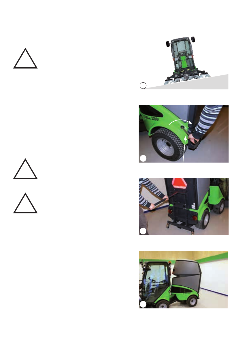
2.1 Assembling the hopper frame
The hopper frame is folded up and hung on the hopper on
delivery. Assembling the hopper frame:
1. Take the hopper frame down and unfold it. (Picture 1)
2. Put the frame together using the two bolts supplied.
(Pic ture 2)
Moving the hopper frame
The hopper frame can be transported on the suction
sweeper. Fold it down in reverse order and hang it on the
hopper.
Attention
The hopper must never be emptied when
the hopper frame is hanging on the
suction sweeper.
1
Transporting the hopper frame on the hopper
2
Two bolts on the hopper frame
8
Operator’s Manual - City Ranger 2250 - Suction sweeper
Page 9

2.2 Assembly / disassembly
Operator’s manual
Fitting the front brush
1. The locking handle on the A-frame of the basic machine
must be in the unlocked position. (Picture 1)
2. Drive the base machine right up to the A-frame of the
brushes, so the A-frames t into each other.
3. Raise the A-frame by pulling the joystick back until the
brushes are free of the ground.
4. Stop the machine
5. Tilt the attachment into the machine. (Picture 2)
6. Lock the attachment in place by turning the locking
handle on the A-frame all the way to the right. (Picture 3)
Removing the front brush
Follow the tting procedure in reverse order
c
k
o
l
e
d
n
U
1
Locking handle
2
Tilt the attachment into the machine
c
k
o
e
L
d
Operator’s Manual - City Ranger 2250 - Suction sweeper
3
Locking
9
Page 10
Operator’s manual
2.2 Assembly / disassembly - continued
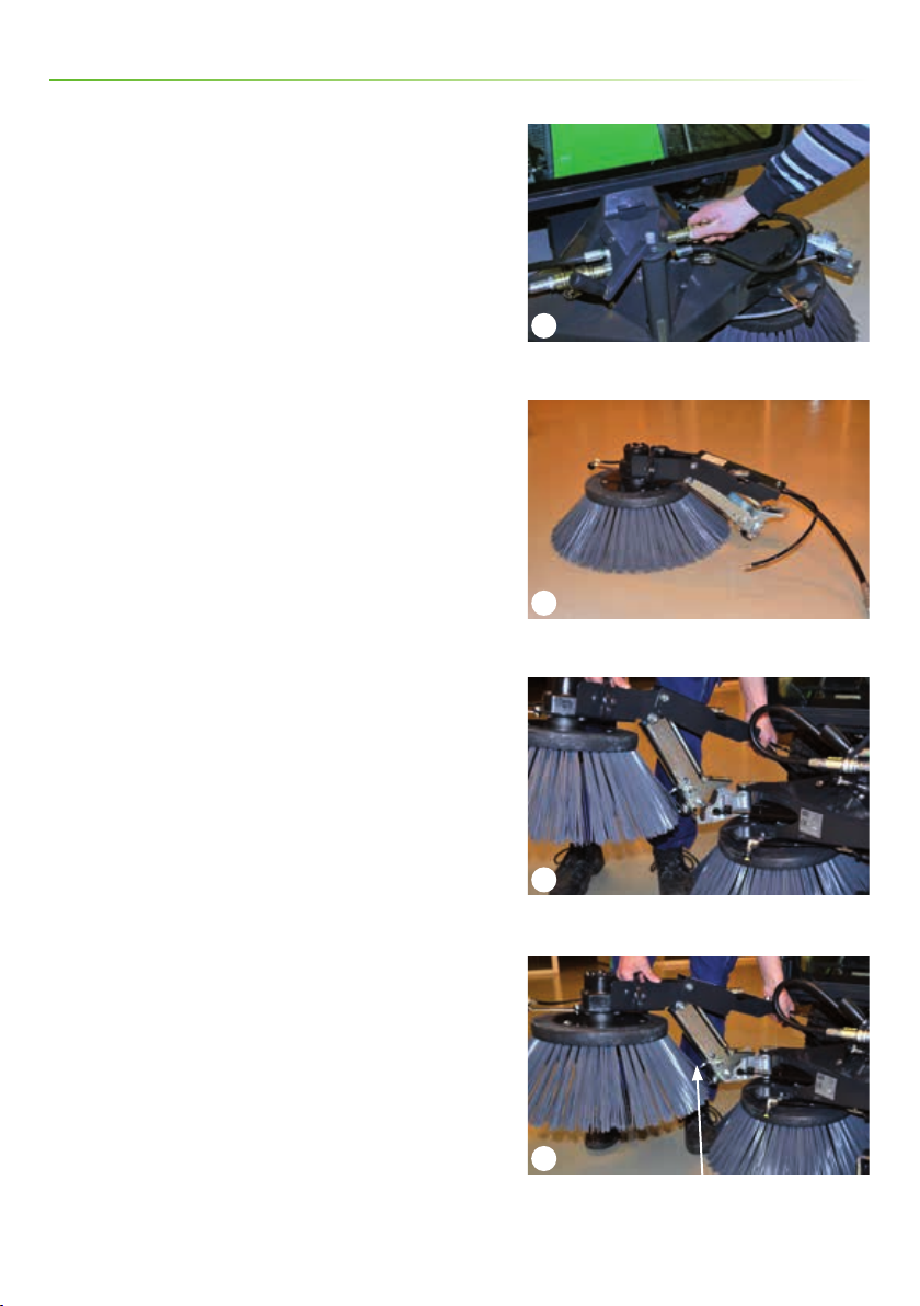
Fitting side-brushes
One or two side brushes can be tted onto the unit. The
side brushes are identical, and can be tted on either side
of the unit, though the water-sprayers must be adjusted
when a side brush is moved over to the opposite side of
the unit.
1. Lower front brushes.
2. Stop the machine.
3. Detach the hydraulic hose. (Picture 1)
4. Lift the side brush under the panel for the hydraulic
motor. (Picture 2)
1
Detach the hydraulic hose
5. Guide the side brush to the front-brush xture.
(Pi cture 3)
6. Snap on the side brush. (Picture 4)
(Continues on page 11)
2
Side-brush
3
Front-brush xture
4
Snap on the side-brush
10
Operator’s Manual - City Ranger 2250 - Suction sweeper
Page 11
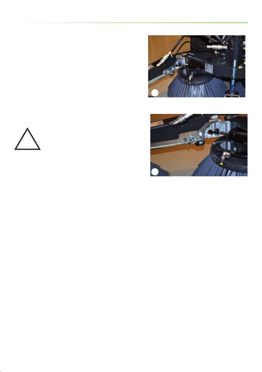
2.2 Assembly / disassembly - continued
7. Fit the hydraulic hoses and the water hoses.
(Pictures 1 and 2)
8. Adjust the water-sprayers.
Operator’s manual
9. Tighten the bolts on the side brushes regularly.
Removing side-brushes
Follow the assembly procedure in reverse order.
Avoid burn injuries
The hydraulic components get hot when
!
operating with the suction sweeper unit.
Do not touch the components before they
are cooled or use gloves.
1
Hydraulic hoses + water hoses on the A-frame are
tted
2
Hydraulic hoses + water hoses on the side brush are
tted
Operator’s Manual - City Ranger 2250 - Suction sweeper
11
Page 12
Operator’s manual
2.2 Assembly / disassembly - continued
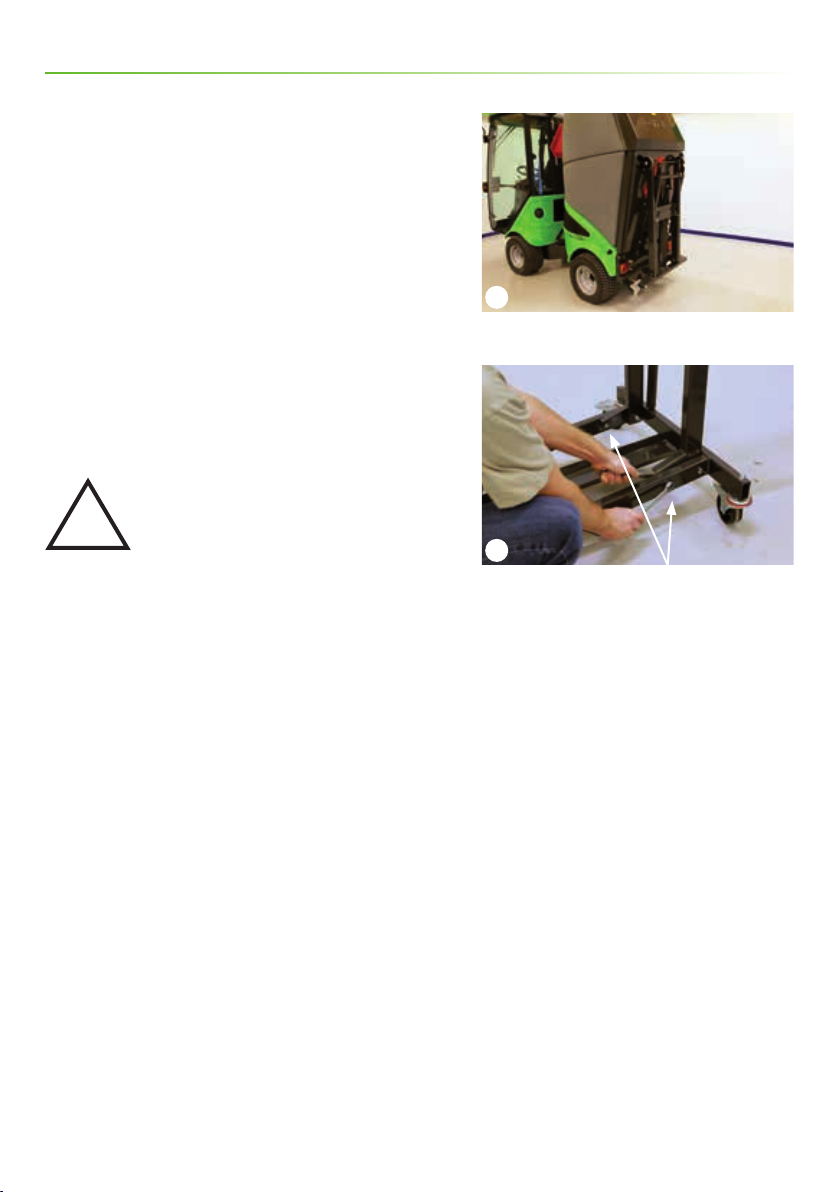
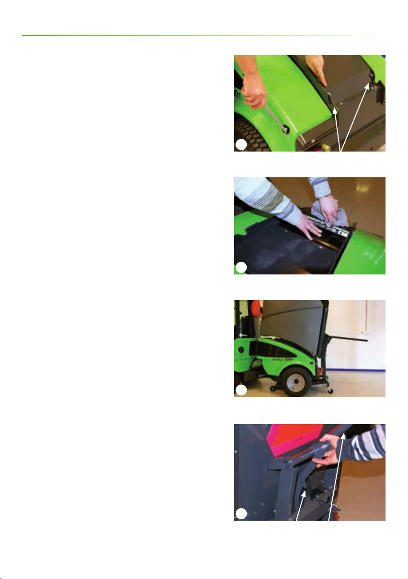
Fitting the hopper
1. Reverse the machine up to the hopper, which is placed
on the hopper frame.
2. Stop the machine.
3. Check the locking handle is in the open position. The
hooks must be in the position shown in the picture.
(Pic tur e 1)
4. Check that the hydraulic couplings are clean and not
dirty. If necessary, wipe with a dry cloth. (Picture 2)
5. Push the hopper in over the loading panel until there
is approx. a 5 cm gap between the hopper frame and the
back bumper. (Picture 3)
The hopper must be centrally placed over the machine.
6. Press the lever down, push the locking latch free from
the barb and lower the hopper slowly over the machine.
(Pic ture 4)
1
Locking lever – unlocked
2
Cleaning couplings
3
Fitting the hopper
12
4
Locking lever
Operator’s Manual - City Ranger 2250 - Suction sweeper
Page 13
2.2 Assembly / disassembly - continued
7. Check the hopper is correctly attached to the machine.
8. Free the hopper frame from the hopper.
Operator’s manual
9. Press the grip on the locking handle in and turn it anticlockwise. Pull the lever out and move it up. (Picture 1)
10. Fix the hopper securely to the machine by turning the
lever 1/3 clockwise. (Picture 2)
11. Push the lever in, opposite way to point 9.
Attention
Keep ngers and hands away as there is
!
Removing the hopper
Follow the tting procedure in reverse order.
a danger of crushing. Keep a good grip of
the hopper frame lever when the hopper
is lowered.
1
The locking handle is pulled out
2
The locking handle is turned
Operator’s Manual - City Ranger 2250 - Suction sweeper
13
Page 14

Operator’s manual
2.3 Checks before start-up
1. Topping-up the water
It is important the water tank is lled up before starting.
(Pic tur e 1)
The water level can be read on the right side of the hopper.
(Pic ture 2)
A water-sprayer is positioned in the hopper (Picture 3)
and a water-sprayer is positioned in front of each brush.
(Pic ture 4)
Two nozzles supply enough water for approx. 140 mins.
of use. Four nozzles supply enough water for approx. 115
mins. of use. If you only use the nozzle in the hopper, it has
enough water for approx. 180 mins. of use.
1
Topping-up the water
2
Tank gauge
14
3
Water-sprayer in the hopper
4
Water-sprayer – front brush
Operator’s Manual - City Ranger 2250 - Suction sweeper
Page 15

2.3 Checks before start-up - continued
2. Checking the rotary lter and turbine
Checking the rotary lter and turbine. (Picture 1)
Remove any dirt before starting (See Section 3.1).
3. Checking the rotary lter water-sprayer
1. Engage the handbrake.
2. Turn the ignition key to position 1 WITHOUT starting the
machine. (Picture 2)
3. Switch the rear PTO ON. (Picture 3)
4. Check water comes out of the water-sprayer below the
lter in the hopper tank. (Picture 4)
Operator’s manual
1
Checking the rotary lter and turbine
4. Adjusting brushes
Correctly adjusted brushes last longer. Make sure the
brushes do not press too hard against the surface being
cleaned (See Section 2.8).
Attention
The suction sweeper must not be used if the water-sprayer
in the hopper is not working.
Stop the turbine immediately if there is imbalance/
vibration in the lter or in the turbine.
A low-level switch has been tted which automatically
stops the water pump if the water tank is empty.
A lamp lights up when there is water in the tank. The lamp
switches o when the suction sweeper unit needs relling
with water.
2
Ignition key – position 1
3
Lamp PTO (rear)
4
Water-sprayer in the hopper
Operator’s Manual - City Ranger 2250 - Suction sweeper
15
Page 16

Operator’s manual
2.3 Checks before start-up - continued
Avoid roll-overs
Check tyre pressure
The tyre pressure must be checked and adjusted to 1.5 bar
(22 psi) when the suction sweeper is attached.
Do not drive the machine in a place where it can slide, tip
or roll. Do not drive on slopes with an incline of more than
10°. (Picture 1)
Transport lock
The transport lock prevents the attachment from lowering
during transport.
How to use the transport lock: Move the handle to the
uppermost position. Lift the A-frame by moving the
joystick up. As the A-frame lifts, the transport lock is
automatically activated. (Picture 2)
How to unlock the transpor t lock: Unhitch the handle
and lift the A-frame to the uppermost position. The
attachment can now be lowered again. (Picture 3)
1
Do not drive on slopes with an incline of more than 10°
2
Transport lock – locked
Max . 10°
16
3
Transport lock – unlocked
Operator’s Manual - City Ranger 2250 - Suction sweeper
Page 17

2.4 Suction sweeper start-up
1. Start the machine
2. Switch ON the (“Rear PTO”), suction begins. Water for the rotar y
lter star ts to ow when the rear PTO is switched on. (Pic ture 1)
3. Set the throt tle to the eco-mode (2,350 rpm) when you s weep light
litter or to ma x. for very dirty jobs. (Picture 1)
4. Start the f ront brushes by activating the (“Front PTO”).
(Pic tur e 1)
5. Adjust the speed of the front brushes to the desired speed with the
(“Front RPM”) button (variably adjustable reduction of rotation).
6. Lower the front brushes by moving the joystick down.
(Pic ture 2)
Operator’s manual
1
Throttle PTO front F1(Water) PTO rear
Front RPM (Speed regulation of the f ront brushes)
7. Engage the weight distribution using the red button on the joystick.
(Picture 2) The f ront brushes will now adjus t to ground conditions.
To adjust the weight dis tribution: Read the operator’s manual for the
basic City Ranger 2250 machine.
8. To spray water using the noz zles on the front brushes, activate the
(“F1”) switch. (Picture 1)
2.5 Using the side brush (optional equipment)
The joystic k controls the side brush’ movements.
A side brush is automatically lowered as it moves out from the
machine.
Using right side brush.
The side brush f ollows the joystick’s sideways movement. Moving the
joystick to the right moves the side brush ou t. Moving the joystick to
the left moves the side brush back in.
Using left side brush.
To switch over to the lef t side brush, push the black button on the
joystick (Pic ture 2) and move the joystick at the same time. The side
brush follows the joystick’s sideways movement. Moving the joystick
to the left moves the side br ush out. Moving the joystic k to the right
moves the side brush back in.
2
Weight distribution Engaging the left side brush
Operator’s Manual - City Ranger 2250 - Suction sweeper
17
Page 18

Operator’s manual
2.6 Using external vacuum hose
Ready for use
1. Engage the handbrake.
2. Switch the rear hydraulics ON while holding the manual
start button down. (Picture 1)
3. Push the throttle to maximum.
4. Turn the change-over handle so the arrow points down.
(Pic ture 2)
5. Lift the locking clip and pull the vacuum hose out.
(Pi cture 3)
6. Pull out the vacuum nozzle. (Picture 4)
1
Manual start button
2
Change-over handle
18
3
Locking clip is released by li fting
4
Handle – vacuum nozzle
Operator’s Manual - City Ranger 2250 - Suction sweeper
Page 19

2.6 Using external vacuum hose - continued
Storing the external vacuum hose
1. Place the vacuum nozzle in the holder. The hose rolls up
together. (Picture 1)
2. Fold the handle in.
3. Snap the handle into the lock.
4. Turn the change-over handle so the arrow points up.
(Pic ture 2)
Operator’s manual
1
Locked Vacuum nozzle Handle
2
Change-over handle
Operator’s Manual - City Ranger 2250 - Suction sweeper
19
Page 20

Operator’s manual
2.7 Emptying the hopper
The hopper can empty directly onto the ground or tip into
a container.
Tipping height 130 cm.
Attention
Before emptying the hopper, make sure that:
A) The machine is on a level surface, and that it is not
“angled”.
B) That there is sucient space for the opened back cover.
1. STOP the front and rear PTO. (Picture 1)
2. Drive to the nearest disposal area.
1
PTO front PTO rear
3. Begin emptying by using the lower joystick to tip the
hopper. (Picture 2)
4. Lower the joystick once the hopper is empty.
(the hopper will move back to its normal position)
Release the handle when the hopper is back in position.
The hopper is tted with a hose-break valve, which will
close if the hopper lowers too quickly. If this happens, raise
the hopper a little again and then lower it slowly.
(Pi cture 3)
Attention
The rear hatch must not be opened until suction has
ceased. Otherwise there is a risk of personal injury. The
suction continues to run for approx. 15 s after the turbine
has been switched o (PTO rear).
There is a risk of crushing while the hopper is being
emptied.
Make sure the hopper is completely lowered after
emptying!
2
Bottom joystick
3
Hopper tips all the way back
20
Operator’s Manual - City Ranger 2250 - Suction sweeper
Page 21

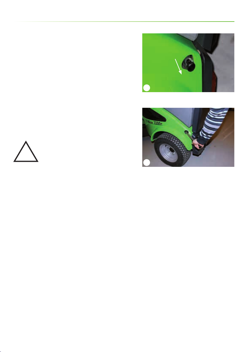
2.8 Emptying the hopper for water
The water in the hopper can be emptied by unscrewing
the drain plug. (Picture 1)
2.9 Protect the suction sweeper against ice during the winter
1. Pouring a solution of water and anti-freeze into the
water tank – the same solution as if protecting a sprinkler
system against ice.
2. Turning the turbine and water supply to the front
brushes on, the liquid runs through the whole system and
protects it against ice.
3. Alternative, completely empty the water in the tank and
the rest of the system.
Operator’s manual
1
Drain plug
Operator’s Manual - City Ranger 2250 - Suction sweeper
21
Page 22

Operator’s manual
2.10 Adjustment
1. Adjusting brushes
Adjust the brushes using the nose wheel. Adjust the
brushes so that they precisely brush the ground to give a
maximum clearing width, with half of the brush bristles
touching the ground at any given time. (Picture 1)
2. Adjusting the vacuum nozzle
Adjust the distance between the surface and vacuum
nozzle using the height-adjustment xture. (Picture 2)
With the nose wheel screwed all the way down, the
distance between the hydraulic motor and the ground
is 95 mm. (Picture 3) This adjustment also aects the
coupling between the front brushes and the machine.
Check that the vacuum hose is tightly connected to the
vacuum nozzle.
3. Adjusting the angle of the external side brush
Vertical
1
Nose wheel
2
Height-adjustment xture
1. Loosen the counter nut. (Picture 4)
2. Unscrew the parallel rod. The forward edge of the brush
lowers.
3. Screw the parallel rod back. The forward edge of the
brush lifts.
4. The optimal brushing position is with the forward 1/3 of
the brushes in contact with the ground.
22
3
Ground clearance
4
Counter nut – parallel rod
Operator’s Manual - City Ranger 2250 - Suction sweeper
Page 23

2.10 Adjustment - continued
Horizontal
To adjust the side brush horizontally, loosen the 3 nuts on
the side brush and turn the brush head manually.
(Pic tur e 1)
4. To adjust side brush lifting position
The side brushes can be adjusted so that they either
remain brushing in the lowered position or are raised
when moved towards the middle.
To adjust the side brush so that it is raised when
travelling towards the middle
A) Pull back the pin.
B) Push the wheel back.
C) Put the pin into the rear position. (Picture 2+3)
Operator’s manual
1
3 nuts
2
Pin Wheel
Operator’s Manual - City Ranger 2250 - Suction sweeper
3
Side brush raised
23
Page 24

Operator’s manual
2.10 Adjustment - continued
To adjust the side brush so that it remains lowered
when travelling towards the middle
A) Pull back the pin.
B) Push the wheel forward.
C) Put the pin into the front position. (Picture 1+2)
1
Pin Wheel
2
Side brush lowered
24
Operator’s Manual - City Ranger 2250 - Suction sweeper
Page 25

2.11 High-pressure cleaner (optional
equipment)
The high-pressure cleaner is stored in a hollow space
behind the hopper. To gain access to the high-pressure
cleaner, pump and lter, the hopper must be tipped as far
back as possible. (Picture 1 + 2)
The spray lance, hose and switch valve are located on the
back of the machine. (Picture 3)
The high-pressure cleaner runs on the same hydraulic
connector as the suc tion tank turbine. To switch between
turbine and high-pressure cleaner, activate the switch
valve on the back of the hopper.
Operator’s manual
1
High-pressure cleaner
2
Filter Pumps
Operator’s Manual - City Ranger 2250 - Suction sweeper
3
Switch valve Spray lance Hose
25
Page 26

!
Operator’s manual
2.11 High-pressure cleaner (optional
equipment) - continued
To start the high-pressure cleaner
1. Turn the switch valve to the left
(to run the high-p ressure cleaner).
(Pic tur e 1)
2. Start the hydr aulic system ”manual operation”
(see sect ion 2.6).
The machine should run at about 2,000 rpm.
3. Remove the spray lance and hoses from the hose rac k. Clean as
required.
4. To stop the high-pressure cleaner, turn the switch valve to the
right. (Picture 1)
5. Release the pressure in the water hose by activating the spray
lance.
6. Roll the hose tightly in a cloc kwise direction and return the spray
lance to its holder. It is important that the hose is rolled tightly so
that it ts snugly into the hose holder.
1
Switch valve
NB
Excessive rpm will not cause any noticeable
increase in water pressure as the ow of oil to the
high-pressure pump is regulated.
The water pump is tted with a bypass function to ensure that
the pump does not overheat in ”neutral”, when the high-pressure
cleaner is not using water. We recommend that you do not run the
high-pressure cleaner in ”neutral” for more than 10 minutes at a
time
Important
The water pump must never run when the water
tank is empty. If the water pump runs for more
than 1 min. without water, the pump will be
damaged and will fail relatively quickly.
Warning
When you turn the switch valve back to ”run
turbine”, the suction system immediately restar ts.
!
!
26
Operator’s Manual - City Ranger 2250 - Suction sweeper
Page 27

3.1 Cleaning/replacing lter system and
turbine
Daily cleaning and maintenance will extend the lifetime of both the
machine and the attachment.
Clean the suc tion sweeper with water af ter use. Avoid high pressure
cleaning of the snap couplings.
Clean the snap couplings with a cloth. (Picture 1)
Cleaning/replacing lter system and turbine
Attention
In case of imbalance in the lter or turbine, the machine must be
stopped immediately to prevent vibration damage.
Checking the lter and turbine daily
Dirt can c ause imbalance in the rotar y lter and turbine. It must
be removed imme diately! Give special attention to the lter and
turbine while the machine is operating in dicult conditions.
Cleaning the rotary lter and turbine
1. To remove the turbine inspection hatc h, loosen the lever on the
hopper. Rinse the turbine clean with water, preferably using the
high-pressure cleaner. (Picture 2)
Service and maintenance
1
”Clean the snap couplings with a cloth”
2
Inspection hatch
2. If the turbine is very soiled, remove the rotary lter and rotary
lter grill to give better acce ss for cleaning the turbine.
(Pic ture 3+ 4)
3. Check for dir t on the turbine and clean. (Picture 4)
4. Flush the turbine until it is clean. A high-pressure cleaner is
recommended for this purpose.
5. Attach the rot ary lter grill and rotar y lter. Bolt should be
tightened to 45 Nm of torque.
If the rotar y lter cannot be cleaned or is worn, it should be replaced.
New lters can be ordered f rom an authorised Nilsk Outdoor
dis trib utor.
Replacing the turbine
The turbine should be replaced at an authorised Nilsk Outdoor
dis trib utor.
Operator’s Manual - City Ranger 2250 - Suction sweeper
3
Rotary lter grill
4
Turbine
27
Page 28

Service and maintenance
3.2 Maintenance
Cleaning the water-sprayer
1. Use a 5 mm Allen key to remove the Allen screw in the end of the
spray pipe. (Picture 1)
2. Clean the spray hole with a nozzle cleaner or similar.
3. Turn on the basic machine.
4. Use the rear PTO to turn on the water and ush the spray pipe
clean (See Sec tion 2.4).
5. Refasten the Allen screw and t ighten it.
Replacing the brush cylinder
1. Remove the brush par t from the A-frame on the basic machine.
2. Remove the bolt that holds the vac uum nozzle. Pull up the
vacuum nozzle. (Picture s 2+3)
3. Remove the brush c ylinder bolt and pull the br ush o. (Picture 4)
4. Loosen and remove screws and the xing plate that hold the
rubber seal in place. - Fit new rubber seal, and replace the xing
plate and screws.
You can order new brush cylinders and rubb er seals from your
authorised Nilsk Outdoor distributor.
NB!
Nilsk Outdoor Division recommends that you replace the rubber
seals and brush cylinders at the same time.
New cylinder brushes c an be ordered from an authorised Nilsk
Outdoor distributor.
1
Spray pipe
2
Vacuum nozzle Bolt
3
The vacuum nozzle pulls up
Attention
Give caref ul attention to string or any other similar material stuck to
the cylinder brush. Such material must be removed.
To avoid excessive wear and tear, it is important that you readjust
the front br ush. See section 2.10.
28
4
Cylinder brush
Operator’s Manual - City Ranger 2250 - Suction sweeper
Page 29

3.2 Maintenance - continued
Replacing the two front brushes
1. Loosen the three bolts on each brush plate. (Picture 1)
2. Remove the old brush (The brush plate should not be
removed from the hydraulic motor).
3. Fit new brushes. New brushes can be ordered from an
authorised Nilsk Outdoor distributor.
The brush cylinder in the vacuum nozzle should also be
replaced when replacing the t wo front brushes. This
ensures optimal cleaning and sweeping. The side brushes
can be replaced independently, as required.
Replacing the vacuum hose
The vacuum hose should be replaced at an authorised
Nilsk Outdoor distributor.
Ice protection
When the suction sweeper is stored away during the
winter, or is in a very cold environment, it can be protected
against ice by:
Service and maintenance
1
Brush plate Bolts
1. Emptying the water tank (See Section 2.8).
2. Pouring approx. 10 l of anti-freeze solution into the
water tank.
3. Turning the water pump on (See Section 2.4).
4. When the solution begins to ow out of the front
brushes and the turbine sprayer, this liquid can be bled
from the tank and subsequently re-used.
Operator’s Manual - City Ranger 2250 - Suction sweeper
29
Page 30

Service and maintenance
3.2 Maintenance - continued
Imbalance/vibrations in the hopper
In certain circumstances imbalance/vibrations can occur in
the hopper. The reasons for this may be:
1. Dirt stuck in the rotary lter, rotary lter grill or turbine.
2. The lter or turbine is damaged. New lters, rotary lter
grills and turbines can be ordered from an authorised
Nilsk Outdoor distributor.
30
Operator’s Manual - City Ranger 2250 - Suction sweeper
Page 31

3.2 Maintenance - continued
Blocked vacuum nozzle
1. Stop the machine.
2. Remove the front brushes.
Service and maintenance
3. Reverse the machine away from the front brushes.
4. Start suction.
5. Take the cleaning tool that is xed on the top of the
hopper (under the external vacuum hose). (Picture 1)
6. Remove any material blocking the nozzle with the
cleaning tool. (Picture 2)
7. Put the cleaning tool back.
8. Attach the front brushes.
Attention! Always clean the vacuum hose from below.
Cleaning under the raised hopper
If the hopper is raised and you need to clean under it, the
following should be obser ved:
1. The hopper is fully-tipped.
2. The machine is o and the handbrake is engaged.
3. The hopper’s own weight will hold it in position.
(Pi cture 3)
1
Cleaning tool
2
Cleaning tool Vacuum hose
3
Hopper fully-tipped
Attention
The hopper has a break valve tted to ensure the hopper
continues to lift to its full height if a hydraulic hose breaks.
Operator’s Manual - City Ranger 2250 - Suction sweeper
31
Page 32

Service and maintenance
3.2 Maintenance - continued
Daily maintenance of the high-pressure cleaner
No special maintenance is required. However, the highpressure cleaner suction lter must be cleaned once a day.
If you are aware that the water used contains a lot of sand
or iron, you may need to clean the water lter more often.
Check the system for leaks. Check hoses and spray lance
for damage. (Picture 1+2)
Warning
Never use a damaged hose or lance.
!
Ice protection of the high-pressure cleaner
1. To drain the water tank and suction system, open the
drain plug in the tank. (Picture 3)
Check that the water lter is empty. See also Section 3.2.
Ice protection.
2. Replace the drain plug and add liquid anti-freeze.
Replace immediately.
1
Suction lter
2
Spray lance Hose
3. Start the high-pressure cleaner, activate the spray lance
until antifreeze escapes from the nozzle.
4. The system is now protected.
Important
If the system has been exposed to light
!
32
frost, start the pump and allow it to run
in neutral (max. 1 min.) until the water in
the pump has melted.
3
Drain plug
Operator’s Manual - City Ranger 2250 - Suction sweeper
Page 33

3.3 Troubleshooting
Possible causes of lack of water pressure in the
water-sprayers
1. The water tank is empty.
2. The water-sprayers for the brushes are switched o.
3. The water-sprayers are blocked. To clean the
water-sprayers:
– Remove the sprayer holder hose connec tion
(See Section 3.2).
– Clean the sprayer with water or compressed air.
– Ret the sprayer holder hose connection so that it is
spread evenly across the machine.
4. Blocked sprayer in the hopper.
Remove the Allen screw in the end of the spray pipe and
clean the spray hole with a pipe cleaner. Turn the water on
to ush the spray pipe.
Service and maintenance
5. No power to the pump.
6. Faulty sensor or relay.
7. Faulty pump.
8. Water hose is leaking or not tted correctly.
New pumps can be ordered from an authorised Nilsk
Outdoor.
Operator’s Manual - City Ranger 2250 - Suction sweeper
33
Page 34

Service and maintenance
3.3 Troubleshooting - continued
If the sweeping result is not optimal, it may be
caused by the following reasons
Generally
1. Too high operating speed.
2. The adjustment of the brush speed should be adjusted.
3. The distance between the front brushes and the ground
should be adjusted (See paragraph 2.10, adjusting the
brushes).
4. The rotational speed of the engine is too low.
The suction stops when the machine is stopped or
reversing
Check that the star t/stop function for the salt and sand
spreader (extra equipment), behind the left rear cover, is
deactivated. (Picture 1-2)
1
Start /stop f unction - behind the left rear cover
2
Star t/stop ON
34
Operator’s Manual - City Ranger 2250 - Suction sweeper
Page 35

3.3 Troubleshooting - continued
Air leaks
1. The vacuum nozzle does not close tightly on the rubber
sleeve of the vacuum hose (See paragraph 2.10, adjusting
the vacuum nozzle).
2. The rubber gasket between the hopper and the water
tank does not close tightly, is deformed and/or faulty.
Adjust or replace the rubber gasket.
3. The rubber gasket on the rear end of the hopper does
not close tightly. Adjust or replace the rubber gasket.
4. The hopper has not been lowered completely after
emptying.
5. The change-over handle between suction at the front
brushes / remote vacuum hose is placed in the wrong
position (See paragraph 2.6, using remote vacuum hose).
Cleaning/maintenance
1. Blocked or faulty vacuum hose / remote vacuum hose.
Service and maintenance
2. Blocked rotary lter / faulty rotary lter (See paragraph
3.1, cleaning / replacing the lter system).
3. Blocked change-over handle between suction at the
front brushes / remote vacuum hose.
4. The hopper is full.
Operator’s Manual - City Ranger 2250 - Suction sweeper
35
Page 36

Conditions
4.1 Warranty
The warranty period for the materials and manufacture of this suction sweeper is 12 months from
the date of purchase.
In case of errors or defects on the machine within the warranty period, Nilsk Outdoor Division
will carry out the necessary repairs without charge for materials and working hours in accordance
with the terms and conditions listed below.
The scope of the warranty
1. The Nilsk Outdoor warranty is only valid on presentation of the original receipt, supplied with
model description, serial number and date of purchase.
2. Regular checks, adjustments, services and technical alterations are not covered by the
warranty.
3. All inquiries concerning the warranty are to be addressed to the distributor from whom the
machine was purchased.
4. This warranty does not cover faults and defects which cannot be traced back to defects in
material or production errors.
5. This warranty is valid for persons who have legally acquired the machine within the warranty
period.
36
6. In the event of failure to perform and substantiate service in accordance with the applicable
instructions, Nilsk Outdoor Division reserves the right to reject any claim made within the
warranty period.
7. Nilsk Outdoor Division reserves the right to make improvements and design-related
alterations to the machine without being obliged to modify previously delivered models in
relation hereto.
The warranty does not cover
· Wear and tear, accidents, damage to the equipment caused by operating errors, changes to the
construction of the machine or use of non-Nilsk Outdoor spare parts or attachments.
· Machines with illegible serial numbers.
· Damage caused by force majeure such as lightning, ood, re, war, civil disturbance, etc. or
other causes over which Nilsk Outdoor Division has no control.
Operator’s Manual - City Ranger 2250 - Suction sweeper
Page 37

Conditions
4.2 Complaints
All inquiries regarding the machine should be made at the distributor from whom the machine
was purchased. This applies to inquiries concerning normal use, service, maintenance and spare
parts as well as any complaints.
We wish you many years of safe and satisfactory use of your machine.
Best regards
Nilsk Outdoor Division, Nilsk A/S
4.3 Disposal
When, many years from now, your suction sweeper has reached the end of its working life, it
should be disposed of in a responsible manner that conforms to relevant disposal regulations.
1. Used hydraulic oil is to be disposed of at an approved waste disposal facility or site.
2. Remove the plastic and rubber parts and dispose of them in accordance with the applicable
environmental legislation.
3. After the parts mentioned have been removed, the machine is ready to be handed over to one
of your local approved scrap merchants.
Operator’s Manual - City Ranger 2250 - Suction sweeper
37
Page 38

Wearing parts
5.1 Wearing parts – City Ranger 2250 suction sweeper
E09922730 Rotary lter grill
E09709600 Rotary lter
E50000598 Protective guard with
sprayer holder
E09720480 Centre brush
E09722010 Flap for vacuum head 2250
E01100330 Support wheel
38
E04703090 Vacuum hose 150 mm
E01103000 Side brush
E01402100 Side brush water sprayer
E01103200 Side brush, poly/steel
Operator’s Manual - City Ranger 2250 - Suction sweeper
Page 39

Wearing parts
5.1 Wearing parts – City Ranger 2250 suction sweeper - continued
E09725770 Rubber Suction House - right
E50000030 Centre Brush Kit
E09723100 Rubber Suc tion House - left
Operator’s Manual - City Ranger 2250 - Suction sweeper
39
Page 40

Wearing parts
5.2 Wearing parts – City Ranger 2250 high-pressure cleaner
E30201422 Spray Lance
E30201424 Filter Cartridge
E30201423 Hose
40
Operator’s Manual - City Ranger 2250 - Suction sweeper
Page 41

Notes
Operator’s Manual - City Ranger 2250 - Suction sweeper
41
Page 42

70100071-01 EN
Nilsk Outdoor Division
Nilsk A/S
Transport vej 27
DK-7620 Lemvig
T. +45 97 81 12 05
F. +45 97 81 12 10
www.nilsk-outdoor.com
info@nilsk-outdoor.com
 Loading...