

Page 1

35mm Film Scanner
COOLSCAN II
Standard Model and Internal-Mount Model
Contents
1. Overview
1.1 Features
1.2 Operating Environment for Standard Model
2. Before Operation
2.1 Inspection
2.2 Components
2.3 Notes on Use
2.4 Cleaning the Unit
3. Parts Identification
3.1 Main Unit
3.2 Status Display LED
3.3 Strip Film Holder FH-2
4. Setting Up the Standard Model
4.1 Before Connection
4.2 Connecting the Power Cord
4.3 Connecting the SCSI Cable
4.4 Setting the SCSI ID
User’s Manual
- 1 -
Page 2

5. Setting Up the Internal-mount Model
5.1 Before Installing
5.2 Installing the Internal-mount Model
5.3 Setting the SCSI ID
5.4 Terminating the SCSI Chain
5.5 SCSI Cables Used with Internal Scanners
5.6 Connecting to the Computer SCSI
5.7 Setting Up a SCSI Chain with the Scanner
6. Operation
6.1 Turning on the Power
6.2 Film Insertion
7. Troubleshooting
Appendix: Specifications
Index
- 2 -
Page 3

Cautions
• The reproduction of all or part of this manual without our
permission is prohibited.
• The information contained in this manual is subject to change
without notice.
• We have made every effort to produce a perfect manual,
but should you find any mistakes, we would be grateful if you
would kindly let us know.
• We shall take no responsibility for consequences resulting
from the operation of this product, despite the terms
mentioned above.
Indication
The indications in this manual signify important safety
precautions. In order to use this product safely, please read
every section where these indications are placed before
beginning operation, this product. These indications are also
placed in the table of contents so users can find them easily.
Indication
The indications in this manual signify the need for caution
when using the products. These indications are placed in
sections that should be read by users before beginning
operation, in order to avoid damage to the product.
Trademark Information
Macintosh is a registered trademark of Apple Computer, Inc.
Microsoft is a registered trademark and Windows is a trademark of Microsoft
Corporation.
IBM PC/AT is a trademark of International Business Machines Corporation.
Other brand or product names are the trademarks or registered trademarks of
their respective holders.
- 3 -
Page 4

Federal Communications Commission (FCC)
Radio Frequency Interference Statement
This equipment has been tested and found to comply with the
limits for a Class B digital device, pursuant to Part 15 of the FCC
Rules. These limits are designed to provide reasonable
protection against harmful interference in a residential
installation. This equipment generates, uses, and can radiate
radio frequency energy and, if not installed and used in
accordance with the instructions, may cause harmful
interference to radio communications. However, there is no
guarantee that interference will not occur in a particular
installation. If this equipment does cause harmful interference
to radio or television reception, which can be determined by
turning the equipment off and on, the user is encouraged to try
to correct the interference by one or more of the following
measures:
CAUTIONS
Modifications
The FCC requires the user to be notified that any changes or
modifications made to this device that are not expressly
approved by Nikon Corporation may void the user's authority
to operate the equipment.
SCSI Cable
Please use the SCSI cable listed on page 5 in the user's Manual
supplied with the scanner. Using other interface cables may
exceed the limits of the class B Part 15 of FCC rules.
Notice for customers in Canada
CAUTION
This class B digital apparatus meets all requirements of the
Canadian interference Causing Equipment Regulations.
• Reorient or relocate the receiving antenna.
• Increase the separation between the equipment and
receiver.
• Connect the equipment into an outlet on a circuit different
from that to which the receiver is connected.
• Consult the dealer or an experienced radio/TV technician for
help.
ATTENTION
Cet appareil numérique de la classe B respecte toutes les
exigences du Règlement sur le matériel brouilleur du Canada.
Notice for customers in European countries
ACHTUNG
Dieses Gerät entspricht den Bestimmungen der EG-Direktive
87/308/EEC zur Störungsunterdrückung. Lärmemission kleiner
70 dBA
- 4 -
Page 5
Cautions for Safety
In order to use the COOLSCAN II safely and correctly, and to
prevent problems, pay careful attention to the following points:
• Use an AC power supply of 50/60Hz and a voltage of from
100V–240V. Be sure to use a power cord rated for the
appropriate voltage.
At voltages of more than AC 125V:
use a power cord that complies with the safety standards of
the country in which it is used, which has a plug rated for AC
250V, 15A (NEMA 6P-15) and insulation of SVT type or
better, and which is more than AWG18 in thickness.
At voltages of AC 125V or less:
use a power cord that complies with the safety standards of
the country in which it is used, which has a plug rated for AC
125V, 10A and insulation of SVT type or better, and which is
more than AWG18 in thickness.
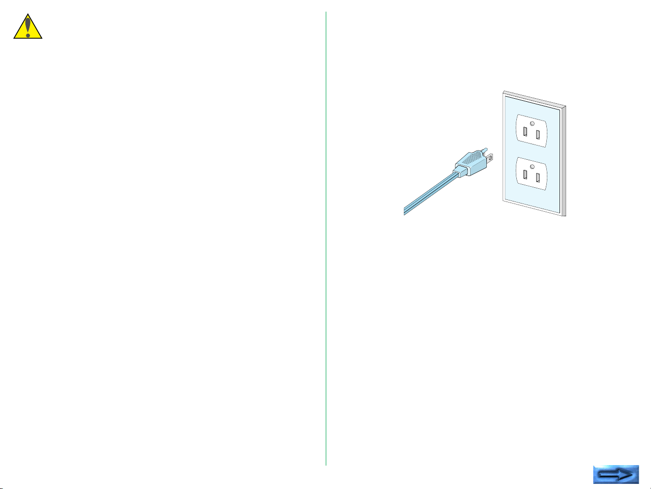
• Be sure that the electrical outlet of the power supply is
grounded. Conduct the grounding in common to the other
machines it is being connected with. Unless common
grounding is conducted, ground loop will occur, which will
cause electric shock and noise static.
* The shape of the plug depends
on the country of use.
• Do not conduct the grounding to a gas pipe or a water pipe.
- 5 -
Page 6
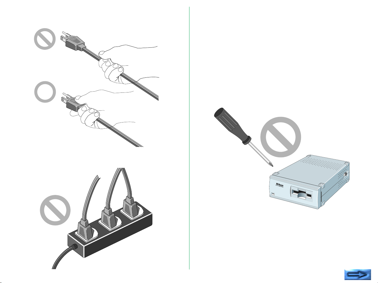
• When plugging in or unplugging the power cord, be sure to
touch only the plug.
• Do not extend the power cord of the product, as this may
cause malfunction. This can cause breakage and failure.
• Do not connect or remove peripheral equipment while the
power switch is on. This can cause breakage and failure.
• Do not unplug the power cord while the power switch is on.
This can cause breakage and failure.
• Do not move the Unit while the power switch is on. This
can cause breakage and failure.
• Once the power switch has been turned off, wait at least five
seconds before turning the power switch on.
• On no account disassemble the Unit. The high voltage parts
inside the unit can cause electric shock.
• Do not insert any foreign objects inside the unit. If
flammable objects, metal, or water come in contact with the
interior of the unit, failure, fire, and/or an electrical shock may
result.
- 6 -
Page 7

• Avoid harsh substances such as alcohol, benzine, thinner, or
pesticides, as failure, fire, and/or an electrical shock may
result.
• Do not subject the unit to any strong shocks. This can cause
breakage and failure.
• Do not place heavy objects on the unit.
- 7 -
Page 8

• Do not pull or bend the SCSI cable. This can cause the
cable to malfunction.
5
If You Notice Anything Abnormal
If unusual noise, odor or smoke occurs, switch the Unit off
immediately and disconnect the power cord and the SCSI cable.
Contact your retailer or Nikon sales representative in your
country.
- 8 -
Page 9
Storage and Operating Locations
Proper storage will ensure the long life of the Unit. In order to
avoid internal dust while being stored, it is recommended that
an appropriate cover be used on the Unit.
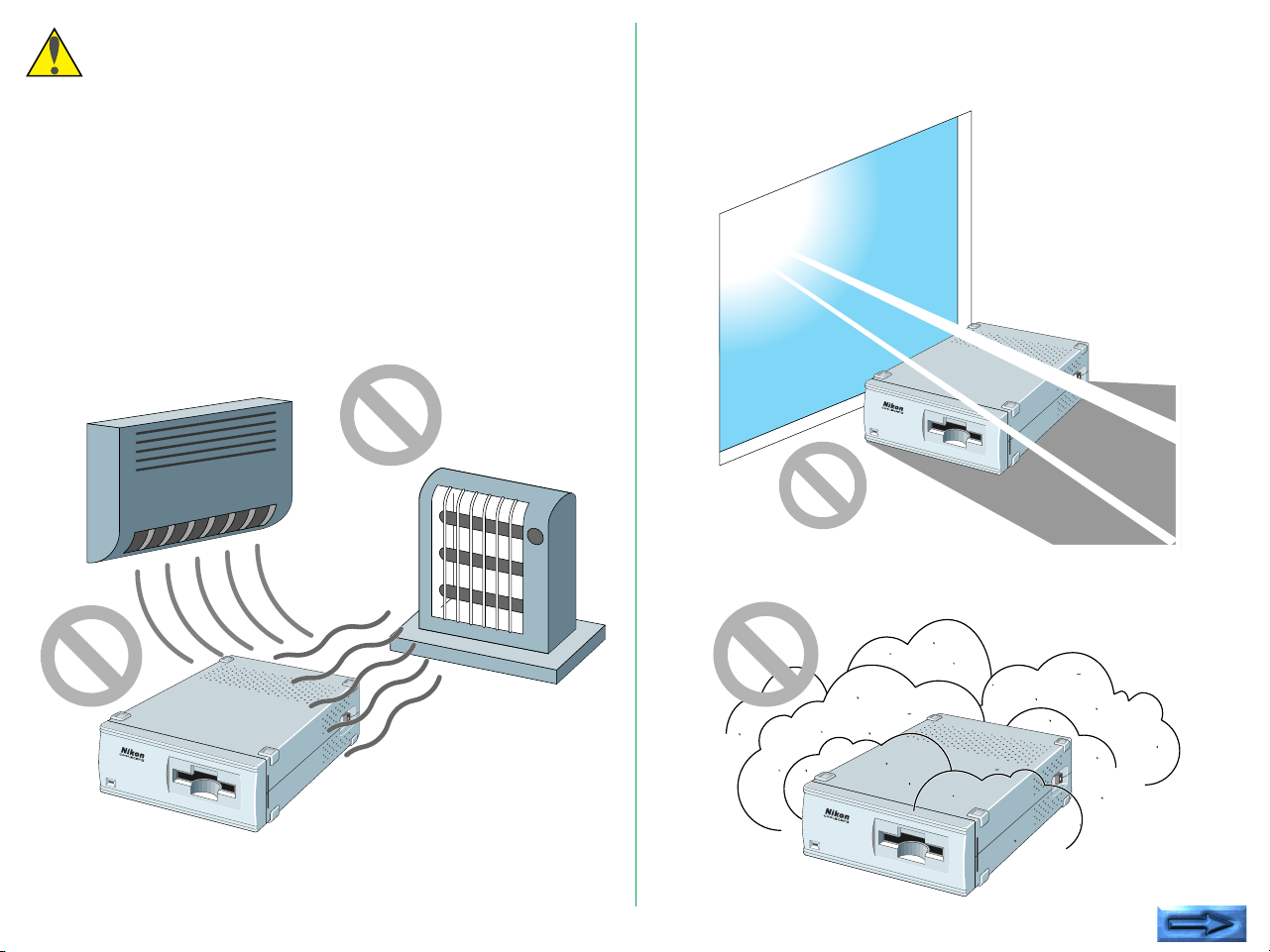
Do not store or use where:
• The temperature is above 95°F (35°C) or below 50°F
(10°C), the temperature changes drastically, or condensation
occurs.
• The humidity exceeds 80%.
• The Unit is exposed to direct sunlight.
• The atmosphere is excessively dusty.
- 9 -
Page 10
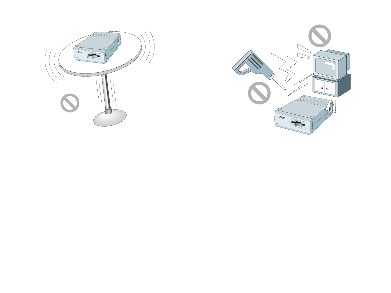
• The Unit may be subjected to excessive vibration.
• The Unit is placed on tilted surface.
• The Unit is exposed to electrical noise and interference from
other equipment nearby.
Leave sufficient space around the unit to ensure that the
ventilation slots are not blocked. Blocking these slots may cause
an internal heat build-up.
Place the unit on a level and stable surface for operation. If
operated in any other way, problems will occur.
- 10 -
Page 11

Cautions for Operation
When Taking the Unit Out of The Country
• Don't carry the Unit or film while scanning. This can cause
breakage and failure.
• When moving the scanning stage, don't touch or unmount
the film holder. This can cause breakage and failure.
• Don't use a slide mount more than 3mm thick. If the slide
mount surface is not smooth, you may feel some resistance
when mounting or unmounting the slide.
• Don't force the slide mount or strip film holder into or out
of the scanner if it does not move smoothly. This can cause
breakage and failure.
Transportation Precautions
When transporting the Unit, pack the unit with the original
package box and packing material provided by Nikon.
The use of this product may violate local laws and restrictions in
some countries. If this is the case, we cannot bear any
responsibility for any violations resulting from the use of this
product.
- 11 -
Page 12

Notice concerning prohibition of copying or
reproduction
Note that simply being in possession of material which has been
copied or reproduced by means of a scanner may be
punishable by law.
• Items prohibited by law from being copied or reproduced
Do not copy or reproduce paper money, coins, securities,
government bonds, or local government bonds, even if such
copies or reproductions are stamped “Sample”.
The copying or reproduction of paper money, coins, or
securities which are circulated in a foreign country is
prohibited.
The copying or reproduction of unused postage stamps or
post cards issued by the government without obtaining
approval from the government is prohibited.
The copying or reproduction of stamps issued by the
government and certified documents stipulated by law is
prohibited.
• Cautions on certain copies and reproductions
The government has issued cautions on copies or
reproductions of securities issued by private companies
(shares, bills, checks, gift certificates, etc.), commuter passes,
or coupon tickets, except when a minimum of necessary
copies are to be provided for business use by a company.
Also, do not copy or reproduce passports issued by the
government, licenses issued by public agencies and private
groups, ID cards, and tickets, such as passes and meal
coupons.
• Comply with copyright notices
The copying or reproduction of works such as books, music,
paintings, woodcut prints, maps, drawings, movies, and
photographs which are copyrighted creative works is
prohibited except when it is done for personal use at home
or for similar restricted and non-commercial use.
- 12 -
Page 13

1. Overview
1.1 Features
Thank you for purchasing the Nikon 35mm Film Scanner
COOLSCAN II. This manual describes the procedures for
unpacking, setting up, and connecting the scanner, with
emphasis on hardware use and precautions.
Please read the sections appropriate for the scanner you are
using, to ensure proper operation.
For an explanation of how to scan and reproduce images with
COOLSCAN II, please refer to the software manual.
We hope that you will find this manual helpful.
The COOLSCAN II is capable of scanning 35mm film (color/
monochrome, negative/positive) at high speed and high
resolution.
• 3-color, high-brightness LED illuminant, eliminates the need
for illuminant maintenance
• High-speed single-pass scanning capability
• High quality images produced using an 8-bit A/D converter
• Maximum pixel count of 2,592 x 3,888 and high resolution
of 2,700dpi (on film surface)
• Auto-focus function, eliminating the need for manual focusing
• Compact, lightweight design, with low power consumption
- 13 -
Page 14
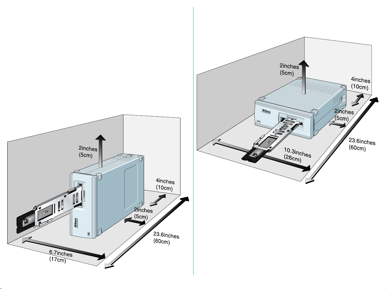
1.2 Operating Environment for Standard Model
Leave extra space around and above the unit to ensure smooth
operation. Please refer to the drawings below for the amount
of space to be provided.
If possible, place a suitable cover over the unit to avoid dust
accumulating when it is not being used.
For vertical installation
For horizontal installation
- 14 -
Page 15

2. Before Operation
2.1 Inspection
Inspect the package to see whether any damage has occurred
during shipment. If there is any damage to the package, please
contact your retailer directly and do not unpack the unit.
2.2 Components
When you open the package, check whether all the items are
present. If there are any missing items, please contact your
retailer immediately.
Standard Model
The following items are included with your COOLSCAN II
standard model package.
Power cord (1)
* The shape of the plug depends
on the country of use.
SCSI cable (1)
(50pin full pitch Dsub 25pin)
Terminator (1)
Main Body (1)
FH-2 Strip Film Holder (1)
User’s manual(s)
Software disk(s)
- 15 -
Page 16

Internal-mount Model
The following items are included with your COOLSCAN II
Internal-mount model package.
Main Body (1)
Guide rail (1)
SCSI 50-pin flat cable (1)
FH-2 Strip Film Holder (1)
Terminator (1)
User’s manual(s)
Software disk(s)
- 16 -
Internal Power Cable (1)
Page 17

2.3 Notes on Use
2.4 Cleaning the Unit
• Don’t use a slide mount neither less than 1.1mm nor more
than 3.0mm thick. If the slide mount is not flat on its surface,
you may feel some roughness when mounting or
unmounting the slide.
• Don’t force the slide-mount or strip film holder into or out
of the unit if it does not move smoothly.
• When scanning film, don’t touch or unmount the slide-
mount or film strip holder.
When carrying out routine maintenance and cleaning, ensure
that no volatile liquids such as alcohol, benzine, or thinner come
into contact with the COOLSCAN II as this may cause a failure,
fire, or electric shock.
Please observe the following points:
• Before cleaning, always turn the power off, and pull out the
power plug.
• Since the front cover is made from plastic material, remove
dust with a blower or a dry cloth.
Use a soft, dry cloth to remove dust from the metal panel at
the rear.
• If the unit has become badly soiled, clean with a cloth
moistened with a mild liquid detergent, then dry with a soft
cloth.
Avoid harsh substances such as alcohol, benzine, thinner, or
pesticides, as they may damage the surface, or remove the
exterior finish.
- 17 -
Page 18

3. Parts Identification
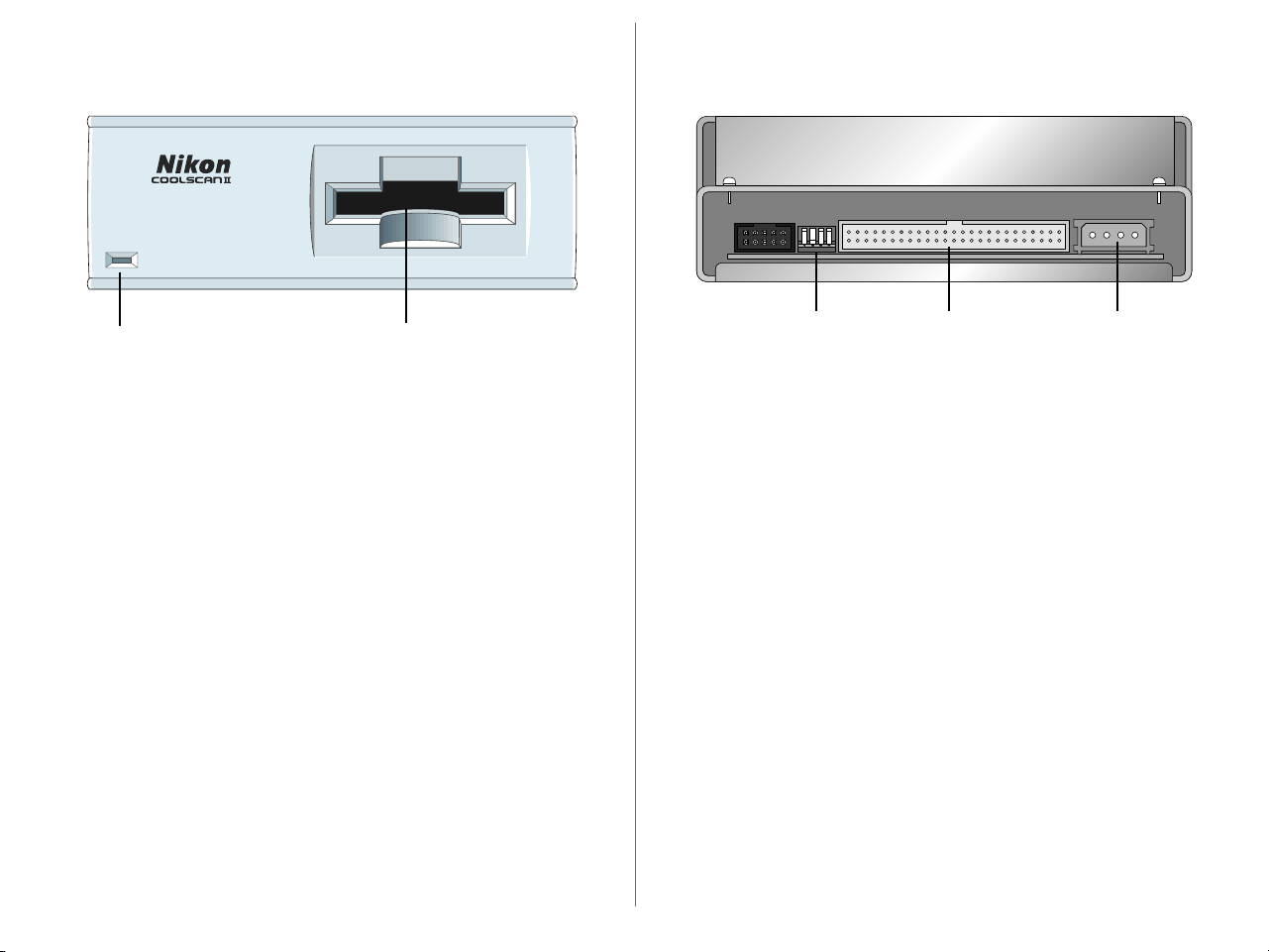
3.1 Main Unit
Standard Model
Ventilation Holes
Status display LED
Film Slot
Film Slot: The film holder is inserted here.
Status display LED:
Shows the scanner status.
Power
Switch
AC Inlet
SCSI Connectors
5
SCSI Connectors:
For SCSI cable connection. No difference
between IN and OUT.
SCSI ID switch: Sets the SCSI ID number. Numbers 0 to 7
are shown and valid.
AC Inlet: Connect to the AC power source with the
power cord provided.
SCSI ID switch
Power Switch: Directly turns the AC power ON/OFF.
Ventilation Holes:
Since air is drawn in through these holes,
make sure that they are not blocked by other
equipment.
- 18 -
Page 19
Internal-mount Model
Film SlotStatus display
LED
Film Slot: The film holder is inserted here.
Status display LED:
Shows the scanner status.
Configuration
DIP switch
SCSI Connector:
For SCSI connection.
Configuration DIP switch:
Sets the SCSI ID number.
Power Connector:
Connect to the power source.
SCSI
Connector
Power
Connector
- 19 -
Page 20

3.2 Status Display LED
3.3 Strip Film Holder FH-2
The display LED is located on the front panel and shows the
scanner status.
Status Display
LED
Steady illumination:
Lights when power is supplied (READY
status).
Blinking (about once every 1.5 seconds):
Blinks slowly during operation (BUSY status).
Also blinks when the power is switched on
and during initialization.
Fast blinking (about 5 times a second):
Blinks fast when an error occurs either in the
scanner or in communication (ERROR status).
Note: The blinking cycle may sometimes be irregular, but this does
not necessarily signify a product malfunction.
This strip film holder can be used with a strip of film containing
up to six images.
Film holder latch
Film holder latch
Aperture
Adaptor cover
Cover latch
Adaptor snap
Upper holder
Lower holder
Lower holder
concave section
(Film sits here)
- 20 -
Page 21

4. Setting Up the Standard Model
For an IBM PC/AT or compatible in which a SCSI board has not
been installed, install a SCSI board as explained in the manual
supplied with the board.
4.1 Before Connection
Before connecting the cables, confirm that all devices, including
the computer system and the COOLSCAN II, are turned off.
POWER OFF
POWER ON
Note: Make sure that the PC is powered off before installing the
SCSI board.
When installing a SCSI board for the first time, be careful not to
set conflicting I/O addresses, interrupt numbers, or graphic
board DMA channels.
- 21 -
Page 22

4.2 Connecting the Power Cord
Before connecting the power cord, confirm that the unit’s
power switch is in the off position.
Insert the female end of the supplied power cord into the AC
inlet located on the rear panel, then insert the plug into the AC
power outlet.
5
Remarks
• The power source must be grounded.
• If possible, try to use an independent electric outlet. If the
unit is connected to an outlet to which an electric household
appliance, such as a vacuum cleaner or air-conditioner, is
connected, the product may experience power source noise
interference.
• Do not extend the power cord of the product, as this may
cause malfunction.
* The shape of the plug depends
on the country of use.
* The shape of the plug depends
on the country of use.
- 22 -
Page 23
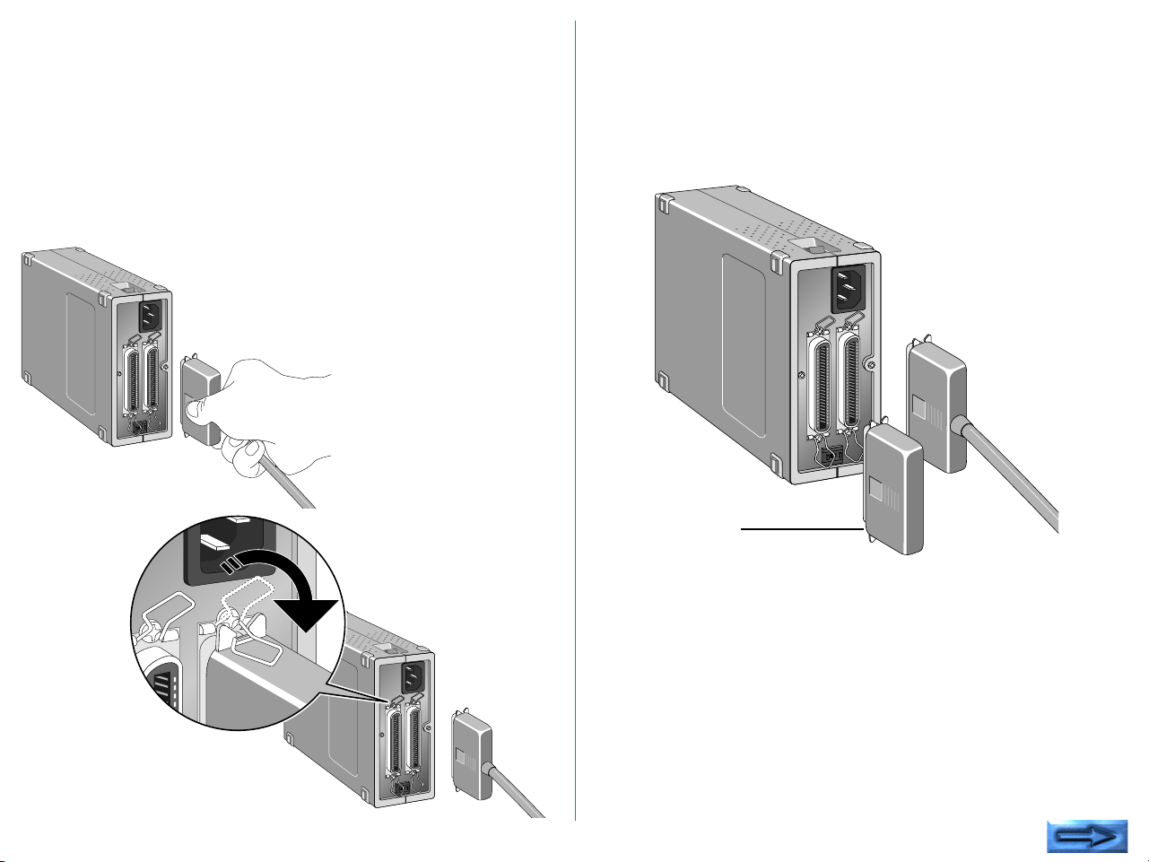
4.3 Connecting the SCSI Cable
5
Before connecting the SCSI cable, confirm that all SCSI devices,
including the computer system, have been turned off.
Connect the unit to the computer using the SCSI cable. After
attaching the connector, be sure to lock it in place. You can
connect the SCSI cable to either of the SCSI connectors on the
rear panel of the unit.
5
If the unit is the only connected SCSI device, or if the unit is
connected at the end of the SCSI chain, attach a terminator
(terminal resistance) to the other SCSI connector. At this point,
remove the terminator of the other SCSI device that has been
placed between them. The terminator is not needed when the
unit is connected between other SCSI devices.
Terminator
Connect SCSI devices in a chain, and attach terminators to both
ends of the chain. Since the terminator is built into the host
computer in most cases, the host computer should be at the
end of the SCSI chain. The operation manuals of some
notebook computers require a terminator to be attached
outside the computer; please refer to the operation manual for
the computer to which the unit is connected.
5
Note: The SCSI cable used for SCSI connection should be of highimpedance type.
- 23 -
Page 24

SCSI Chain Connection with Other Devices
If Scanner is connected at the end of the SCSI chain:
• Connect the 50-pin full pitch connector of the SCSI cable to
the SCSI connector located on the rear panel of the unit,
and insert the other end to the SCSI connector of other
SCSI device.
• Connect the supplied terminator (terminal resistance) to the
other SCSI connector on the rear panel of the unit.
Terminator
If Scanner is connected between the other SCSI devices:
• Connect the 50-pin full pitch connector of the SCSI cable to
the SCSI connector located on the rear of the unit, and
insert the other end to the SCSI connector of other SCSI
device.
• Connect the other SCSI device by using the other SCSI
connector on the rear panel of the unit.
• Connect the supplied terminator (terminal resistance) to the
SCSI device connected at the end of SCSI chain.
- 24 -
Terminator
Page 25

Remarks
• The maximum number of SCSI devices that can be
connected to one computer is eight including the CPU.
When using with a host computer with a built-in SCSI hard
disk or built-in CD-ROM, note that SCSI ID numbers have
been pre-assigned for the host CPU and the SCSI devices.
• The SCSI cable must not be extended beyond a total length
of 19 feet (6 meters), or else failure may result.
• If you use the type of terminator that is inserted between
the SCSI cable and SCSI interface connector, install a
terminator independent of the other SCSI connector of the
COOLSCAN II.
• Terminators must be attached to the devices located at both
ends of the SCSI chain.
If the host computer is a Macintosh, the Macintosh itself will
provide termination at one end of the chain.
If the host computer is an IBM PC/AT or compatible,
equipped with a SCSI board, the SCSI board itself will
present termination at one end of the chain.
Note that when a SCSI chain connection is made inside a
computer, the end of the SCSI device inside the computer
will become the end terminal.
• Before installing a SCSI board, be sure to read the user’s
manual provided with the board. The numbers for the I/O
address, interrupt level (INT) and DMA channel might
conflict with other interface boards and peripheral devices. If
so, change them as explained in the manual.
- 25 -
Page 26

4.4 Setting the SCSI ID
The SCSI ID for the COOLSCAN II is set at “5” when the unit
is shipped. If other SCSI devices are connected to your
computer, make sure that the SCSI ID for the COOLSCAN II is
different from those assigned to other SCSI devices.
Note that in the case of a host computer which has a built-in
SCSI hard disk or built-in CD-ROM, the ID numbers of the host
CPU and each SCSI device have already been assigned.
If the IDs are the same, you must change the ID number of the
other SCSI device or the ID of the COOLSCAN II to avoid any
conflict.
Remarks
• To change the ID, confirm that the COOLSCAN II power is
off. The ID cannot be changed when the power is on.
• As 7 has been assigned for the CPU and 0 has been assigned
to the built-in hard disk for a Macintosh, and 0 and 7 have
also been assigned to other personal computer systems, any
number from 1 to 6 is recommended for the ID number.
• If conflicting ID numbers are assigned, the system might not
function, or important data on the hard disk might be
destroyed. It is therefore essential to check the ID numbers
carefully before connecting the COOLSCAN II.
- 26 -
Page 27

5. Setting Up the Internal-mount Model
The internal-mount scanner is easy to install, following the
procedure described below.
5.1 Before Installing
The internal-mount scanner is shown below. Note that the
front of the internal-mount model is identical to that of the
standard model.
Rear panel
The rear panel of the internal-mount scanner is shown below.
The rear panel contains the DC power connector, SCSI
connector, and configuration DIP switch block.
Front panel
The front of the scanner includes the film slot and the status
display LED.
Film SlotStatus display LED
Configuration
DIP switch
The default DIP switch configuration is shown in Table 5.1. The
meaning of the SCSI ID DIP switch is explained later. The
internal-mount scanner is set at the factory to SCSI ID #5.
DIP Switch Default Usage
1 Closed SCSI ID bit 0 = 1
2 Open SCSI ID bit 1 = 0
3 Closed SCSI ID bit 2 = 1
4 – (Not used)
Table 5.1 Factory set default DIP switch configuration
- 27 -
SCSI
Connector
Power
Connector
Page 28

Both sides of the internal-mount scanner are identical as shown
below. Note the set of two tapped holes on each side. One
set of holes on each side of the scanner will be used for the rails
as shown in this figure.
Locking tab
Top
panel
Front panel Tapped holes
Mounting holes
Guide rail
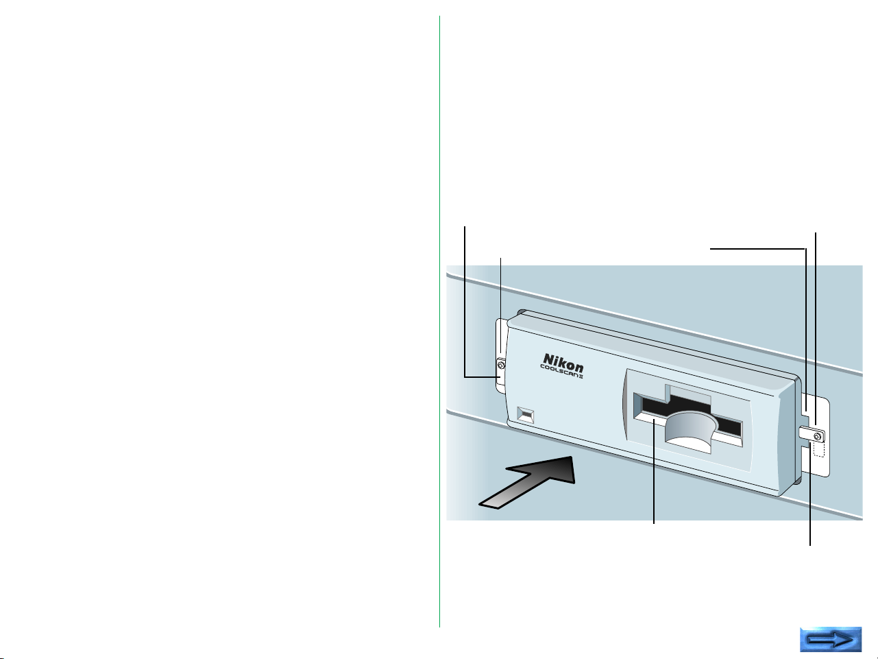
5.2 Installing the Internal-mount Model
To install the internal-mount scanner, first screw the guide rails
provided with the scanner to the two sides of the scanner, then
insert the scanner into the drive bay using the computer drive
bay slots. Connections to the back of the scanner include the
computer power and the SCSI flat cable.
Due to the tight space constraints inside the computer, it is not
possible to connect the cables to the scanner after it has been
installed. The SCSI cable and terminating networks are easier
to connect to the scanner before it is mounted in the drive bay.
The computer power connector is easily connected to the
scanner when the scanner is partially inserted into the drive bay.
- 28 -
Page 29
Installing the guide rails
Different computers have their own special requirements for
mounting devices in an internal drive bay. In most cases, a pair
of guide rails are screwed to the sides of the scanner to enable
it to be slid into the drive bay. These guide rails are also used
to lock the scanner in place.
The computer drive bays
The scanner will slide into a 5 1/4" half-height drive bay as
shown below. To enable film to be inserted into the scanner,
the computer must have a cutout for this drive bay, so that the
drive bay is externally accessible. The scanner will be powered
from the computer using the standard computer drive power
supply connector. The computer mother board needs to have
an available single short connector slot for the SCSI interface
board.
In order for a scanner to be mounted inside the computer, the
computer must have the following:
1. An externally accessible 5 1/4" half-height bay
2. A standard power supply connector
3. A card slot available on the motherboard
Rail stop
(open)
Rail stop screw
Insert the scanner
here
Rail stop screw
Rail slots
Film slot
Rail stop
(closed)
- 29 -
Page 30

The computer drive bay has one or two metal stops screwed
into the tapped holes on the sides of each half-height drive slot.
These should be loosened to allow them to either be removed
or to hang freely so they do not block the drive bay receptacles
for the guide rails. These will be repositioned after the scanner
is installed to lock the scanner in place.
The scanner side mounting holes
Two sets of vertical holes are provided on the sides of the
scanner. These are the top and bottom rail mounting holes.
One set must be chosen according to where the computer
allows the scanner to be positioned in the drive bay. Most
computers require that the bottom set of mounting holes be
used. Position the rails at the bottom of the scanner and, while
holding the scanner, see if the scanner will slide into the bay rail
slots.
The guide rail mounting holes
The guide rails have a tapered end and a non-tapered end. The
tapered end is mounted at the rear of the scanner to facilitate
the scanner’s insertion into the drive bay slot. The non-tapered
end is mounted at the front of the scanner. This flat end allows
the scanner to be locked into position once the scanner is
installed. Certain holes on the rails are elongated vertically,
allowing precise adjustment of the position of the rails with
respect to the scanner. The rails have a set of horizontal holes
that can be used to position the rails forward or backward with
respect to the scanner.
Attaching the guide rails to the scanner
Depending on the type of computer, it may take several tries to
find the best combination of holes on the scanner and rails for
optimal mounting. The face of the scanner has to fit flush with
other peripherals in the drive bays as well as the face of the
computer. In addition, the scanner must slide into the drive bay
without touching any other devices, or the drive bay itself. It
should sit so that the cutout in the computer front panel aligns
with the front of the scanner.
Several attempts may be required to align the scanner in the
computer drive bay. It is often easiest to identify the best holes
while holding the scanner and rails in front of the drive bay.
Choose the position that looks best, then screw the rails into
the side of the scanner loosely and attempt to push the scanner
into the bay. If it fits, remove the scanner, tighten the screws
and continue with the installation. If not, move the rails with
respect to the scanner and try again until it fits.
Sliding the scanner into the drive bay
Before the scanner is inserted into the drive bay, insure that the
DIP switch block is set correctly. In rare cases, it may be
necessary to change the configuration of the DIP switch block.
On no account force the scanner into the drive bay. It
should have a snug fit, yet it should not be necessary to
apply excessive force when pushing in the scanner. If it
does not slide in easily, reposition the guide rails or
visually check the drive bay to see what might be blocking
the path of the scanner.
- 30 -
Page 31
Installing the internal-mount scanner in the
drive bay
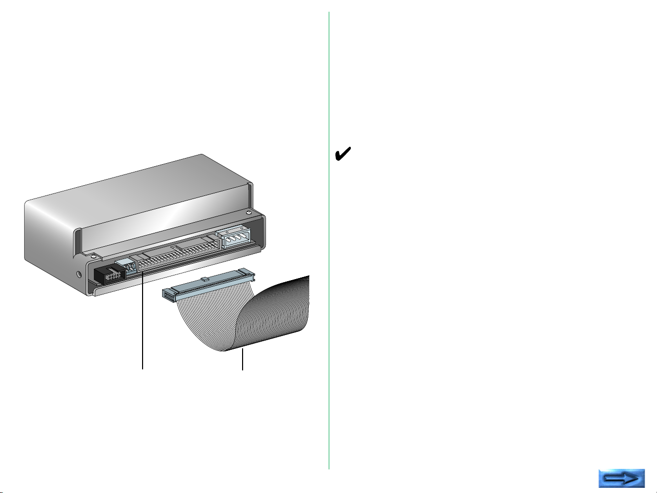
Step 1—Connect the SCSI cable to the scanner
Connect one end of the flat 50-pin SCSI cable to the 50-pin
SCSI connector on the rear of the internal-mount scanner as
shown below. Insure that Pin 1 of the cable is aligned with Pin
1 of the scanner.
SCSI connector
SCSI flat cable
The connectors on both the scanner and the cable are
protected with a protruding tab to force the connector to
mount properly. Note that Pin 1 on the scanner connector and
the cable connector is marked with a triangle, and the wire
associated with Pin 1 has a red stripe on it. Do not force the
cable connector into the scanner. It should snap into place with
moderate force. Make sure that the connector on the cable is
positioned parallel to the connector on the scanner before
applying force. This will reduce the risk of bending any pins.
Warning! Make sure that Pin 1 marked on the scanner
connector mates with Pin 1 of the flat cable connector.
Step 2—Terminating the SCSI chain
The internal-mount scanner needs SCSI termination. Refer to
“5.4 Terminating the SCSI chain” in this chapter for more
information.
Step 3—Loosen the lock down screws
On one or both sides of the drive bay opening are locking
screws. These may be positioned so that they block the access
to the openings in the drive bay where the rails will slide in.
Loosen these screws so that the metal tab does not block
access to the openings. It may be necessary to remove these
tabs. Keep them handy because they will be repositioned in
Step 8 below.
- 31 -
Page 32

Step 4—Feed the computer power connector
Feed the computer power 4-pin connector, through the drive
bay from the inside as far as it will extend out through the drive
bay. Connect the cords with each 12V DC or 5V DC
connector.
Computer power connector
(Typical connector on four wire
cable)
Note: When you establish a ground, connect a grounding
cable (not provided) to the GND screw.
GND screw
Step 5—Slide the scanner part way into the drive bay
Thread the unconnected end of the 50-pin SCSI cable through
the drive bay and pull it through into the inside of the computer
while sliding the scanner rear-first into the drive bay. The
scanner should slide in easily if the rails are properly positioned.
Push the scanner in so that the rear of the scanner aligns with
the computer power connector.
Y-Adapter power connector
(Optional Y-type power connector)
Warning!
The top or bottom of the scanner should not touch anything
when sliding into the computer. Damage can occur to the
scanner or to other devices if the scanner scrapes during
installation.
- 32 -
Page 33

Step 6—Connect the power connector
Connect the 4-pin power connector of the computer to the 4pin power connector of the scanner. Note that both
connectors are keyed so that one side of the connector is
beveled. Be careful to insure that the beveled edges are
properly aligned. Under certain circumstances, it is possible to
force the connector in at an improper angle, thereby creating a
reversed connection. Extreme damage can occur to the
scanner should this happen. Make sure that the connection is
correct.
Note: An optional Y-adapter may be necessary if there are no
available power connectors in the computer.
Warning! Do not attempt to connect power to the scanner
with the computer power on.
5.3 Setting the SCSI ID
Up to eight devices can share a SCSI host. These are each
identified by SCSI ID numbers. Thus, a SCSI ID can have a
value between 0 and 7. There are no implicit regulations
regarding the use of these numbers. Typically, the computer
itself would be SCSI ID number 7, while the SCSI peripherals
would be 0 through 6.
A minimum of two devices must be connected to any SCSI bus.
In this case, one is designated as the initiator while the other is
the target. It is possible to have many configurations of initiators
and targets on a bus. More than one initiator can be present
on a SCSI bus. The typical configuration is one initiator and one
or more targets. The internal-mount scanner is always a target.
In the case we show below, the only initiator is the computer.
Step 7—Slide the scanner into the computer
Once the power connection is made, carefully slide the scanner
the rest of the way into the computer. Pull gently on the SCSI
cable with one hand to provide slight tension on the cable while
the scanner is being pushed in. Do not tug on the cable or
allow the cable to fold while pushing in the scanner.
Step 8—Screw down the rail stops
Once the scanner has been pushed into the computer,
reposition or reinsert the lock tabs mentioned in Step 3 above.
The tabs should slide in front of the scanner guide rails, thereby
locking the scanner in place.
The SCSI ID is typically set by a switch on the rear of the SCSI
peripherals. The default SCSI ID number set at the factory is ID
#5.
- 33 -
Page 34

Determining which ID to use
Remarks
If the scanner is the only SCSI device that will be connected to
the SCSI bus, there is no need to change the SCSI ID from the
preset value.
If the scanner must share the SCSI bus with one or more other
peripherals, it is necessary to insure that no two peripherals
have the same ID. Create a list of SCSI peripherals on the
desired bus, noting the device type and the SCSI ID of that
device. To determine the SCSI ID of the other peripherals,
check the rear of each peripheral for some indication of the
SCSI ID of that device. If there is no indication of the ID
number, consult the peripheral’s user’s manual or call the
peripheral manufacturer to determine the SCSI ID setting.
• To change the ID, confirm that the computer power is off.
The ID cannot be changed when the power is on.
• As 0 and 7 have been generally assigned to the computer
system, any number from 1 to 6 is recommended for the ID
number.
• If conflicting ID numbers are assigned, the system might not
function, or important data on the hard disk might be
destroyed. It is therefore essential to check the ID numbers
carefully before connecting the COOLSCAN II.
If another SCSI peripheral shares the same SCSI ID as the
COOLSCAN II, change the SCSI ID of the COOLSCAN II to
an unused SCSI ID as indicated in the following sections.
- 34 -
Page 35

Setting the SCSI ID on the Internal Scanner
The SCSI ID is set by a set of DIP switches on the back of the
internal-mount scanner as shown below. In most cases, these
DIP switches will not be changed.
Factory default for
COOLSCAN II
If it is necessary to change the default SCSI ID, change the
position of the DIP switches to the proper SCSI ID. Refer to
Table 5.2 for the proper DIP switch values. When changing the
position of the switches, use a pointed instrument to toggle the
switch. Use of a pen or pencil is not recommended, since these
will leave a mark on the switch and make it difficult to
differentiate between the “on” and “off” positions.
SCSI ID DIP #1 DIP #2 DIP #3
0 Open Open Open
1 Closed Open Open
2 Open Closed Open
3 Closed Closed Open
4 Open Open Closed
5 Closed Open Closed
6 Open Closed Closed
7 Closed Closed Closed
Table 5.2 SCSI ID DIP switch values
- 35 -
Page 36

5.4 Terminating the SCSI Chain
The SCSI chain is an electrical bus connecting two or more
devices. It is critical that this bus be correctly terminated for the
SCSI peripherals to work properly.
Termination is an electronics term that applies to the
impedance found at both ends of the bus. The electrical signals
on the SCSI bus are changing rapidly between their digital “on”
and “off” states. To minimize noise, a terminator is placed on
each end of the bus. The effects of this termination may be
subtle, but are critical to the correct operation of the scanner
on bus.
Typically, the computer is located at one end of the SCSI bus.
Assuming this is the case, the SCSI controller in the computer
has to be terminated.
Warning! Incorrect SCSI termination can cause unpredictable
errors.
If one other SCSI peripheral shares this SCSI bus, it also has to
be terminated. If additional SCSI devices are connected to the
bus between the two end SCSI devices, these devices can NOT
be terminated. Only two terminated devices can reside on the
SCSI bus, one at each end.
Improperly terminated SCSI peripherals can fail immediately or
may work correctly for a period of time before generating their
first errors.
Terminating the Internal-mount Scanner
If the LS-20 is at the end of the chain, attach the provided SCSI
terminator as described below.
The SCSI terminator is usually inserted between the SCSI
connector on the LS-20 and the provided SCSI flat cable, as
shown below.
Insert terminator
between these connectors
- 36 -
Page 37

Remarks
• When connecting the terminator to the scanner, insert it
straight, and correctly aligned with the locator key, taking
care not to bend the pins.
• When removing the terminator from the scanner, pull it
straight out, taking care not to bend the pins.
If there is not enough space to connect the terminator directory
to the LS-20, the SCSI connector on the LS-20 should be
attached to the connector stamped in the center of a daisychaining flat cable (not provided), and the provided SCSI
terminator should be attached to the unconnected stamped
connector at one end of this cable.
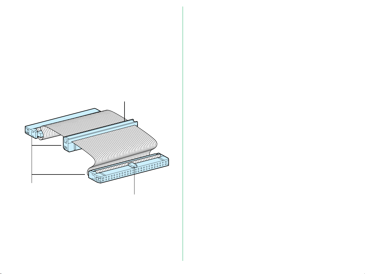
5.5 SCSI Cables Used with Internal Scanners
The internal SCSI cable is a 50-pin flat cable with two identical
molded connectors on each end. One end of this cable will
connect to the SCSI controller while the other end will connect
to the connector on the rear of the internal-mount scanner. A
typical SCSI internal cable is shown below.
SCSI flat cable
SCSI 50-pin connectors
- 37 -
Connector protection key
Page 38

5.6 Connecting to the Computer SCSI
The SCSI port on the computer is a connector located either
inside the computer or on the rear panel of the computer.
There are three basic types of SCSI connectors dealt with in
this manual: the 50-pin internal connector, standard 25-pin
DB25 type connector, and 50-pin external Centronics
connector.
Warning! The SCSI connector should never be connected or
disconnected while the computer is running.
Connecting inside the computer
The SCSI connector inside the computer will be a 50-pin flat
connector as shown below. Note the position of pin 1 and the
key. A wide variety of 50-pin flat connectors are used. Some
may have keys while others do not; some may have Pin 1
clearly marked while others will not; and some may have
mechanical levers to assist in inserting and removing the
connector.
To remove connector: Pry the flat cable
connector out gently with a small, flat- bladed
screwdriver
SCSI connector
- 38 -
Circuit card
SCSI flat cable
Page 39

Care must be exercised when inserting and removing these 50pin connectors. The connecting pins are rather fragile. Follow
the rules below when handling these connectors.
5.7 Setting Up a SCSI Chain with the Scanner
1. Never force the connector in and out.
2. Make sure that the connectors are properly aligned before
inserting.
3. Do not remove a connector from the socket by pulling on
the cable. Instead use a small screwdriver to pry each of
the sides out, a little at a time.
This connector is similar to the connector on the back of the
internal-mount scanner.
The internal-mount scanner is equipped with one SCSI 50-pin
connector. When the scanner is connected as the only other
device on the chain, or as the last device on the chain, the
connector of the 50-pin cable will end at the scanner. This case
is shown below.
Computer internal SCSI
termination set
Computer SCSI
controller
Computer SCSI
connector
- 39 -
Scanner
Insert terminator between
these connectors
SCSI cable
Page 40
Typically, the scanner will be the only peripheral on the internal
SCSI bus. If this is the case, the 50-pin cable provided will work.
In some cases, the scanner will not be the only peripheral on
the internal SCSI bus. When this occurs, the SCSI cable
provided will not work. A special cable with a connector
stamped in the center of the cable as well as a connector
stamped on both ends of the cable will be required. This
special cable is shown below.
SCSI flat cable (not provided)
SCSI 50-pin connectors
Connector orientation key
- 40 -
Page 41

6. Operation
6.1 Turning on the Power
Turn the COOLSCAN II on first, the other SCSI devices next,
and the host computer last. If your scanner is the internalmount model, you need not turn the COOLSCAN II on.
After turning the power on, the LED will begin to blink to
indicate scanner initialization.
POWER ON
The scanner is self-calibrating. A calibration procedure occurs
automatically during power-up. This procedure typically takes
about twenty seconds.
Remarks
• To turn the COOLSCAN II power off, turn the host
computer off first, the other SCSI devices next, and the
COOLSCAN II last (reverse order from switching on).
• Once the power is turned off, please wait five seconds or
more before turning the power on again.
• Do not turn the power off while the scanner is scanning.
• Make sure there is no strip film holder in the scanner during
power-up, or the scanner will not calibrate correctly.
Due to the patented light source, there is no warm up time
necessary for the scanner. Once the scanner has performed its
power-on calibration, it is ready to go.
- 41 -
Page 42
6.2 Film Insertion
The COOLSCAN II can scan different types of 35mm positive/
negative monochrome/color images. In addition, it can scan a
film strip of up to 6 frames or single film ‘chips’.
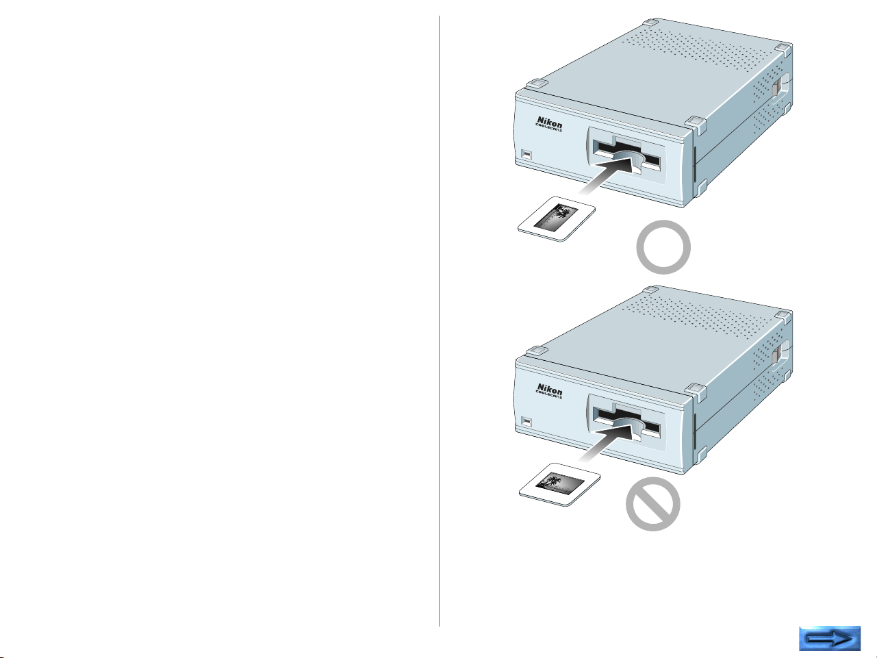
Insertion of Mounted slides
The COOLSCAN II can scan mounted slides as they are.
• Confirm that the thickness of the mounted slides to be
scanned is between 1.1mm and 3.0mm.
• Ensure that the emulsion surface is facing up.
When the scanner is installed vertically, insert the mounted
slide so that the emulsion surface is facing toward the right
(shiny surface facing left).
When the scanner is installed horizontally, insert the
mounted slide so that the emulsion surface is facing
downward (shiny surface facing upward).
* All film has an emulsion surface and a base surface. The
emulsion surface is slightly dull and concave. The base
surface is slightly convex and is shinier than the emulsion
surface.
Insert the mounted slide lengthways until it touches the back of
the scanning stage.
Note: Do not insert the mounted slide so that the width and
length of the mount are reversed. If you do so, the COOLSCAN II
will not be able to scan both sides of the mounted slide.
- 42 -
Page 43

The standard orientation of a mounted portrait or landscape
slide is shown below. If the top and bottom are reversed, the
image can be flipped using software.
Orientation of a portrait slide
Orientation of a landscape slide
- 43 -
Page 44

Insertion of Film Strip
Step 2
Insert the film strip into the attached film holder FH-2, and then
insert the holder into the film slot of the front panel of the unit.
Step 1
Remove the cover latch and open the upper holder. Be sure
the word Nikon, printed on the adaptor cover of the upper
holder is facing upward.
Upper holder
Adaptor cover
Cover latch
Place the film strip on the concave section which is fixed in the
adaptor of the lower holder. Be sure to place the film strip on
the lower holder so that the emulsion surface will be facing
down (the shiny surface will be facing up). The orientation is
correct if the image edge numbers can be read.
Aperture
Film strip
- 44 -
Lower holder
Page 45

Step 3
Step 4
Align each image of the strip film with an aperture in the lower
holder.
Close the upper holder, aligning both ends of the upper holder
and the lower holder.
Fasten the latches at both ends of the holder after securing the
adaptor cover and fastening the cover latch.
Holder latch
Cover latch
Holder latch
- 45 -
Page 46
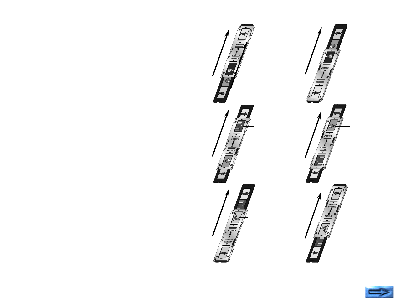
Step 5
Align the image to be read with either of the two apertures in
the silver-colored adaptor frame.
Insert the film holder in the film slot of the front panel in the
scanner , with placing the aperture through which the image is
to be read toward the slot.
The film holder can be inserted into the COOLSCAN II from
either end. Decide the insertion direction of the film holder
according to which image is to be read.
The first
image will be
read.
The fourth
image will be
read.
- 46 -
The second
image will be
read.
The third
image will be
read.
The fifth
image will be
read.
The sixth
image will be
read.
Page 47
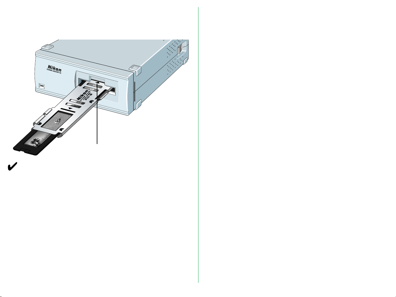
Step 6
Insert the film holder until it touches the back of the stage and
is aligned with the edge of film slot, as shown.
Mark
Remarks
• Do not force the film holder into the scanner.
• Though the film holder is made of plastic, it will be damaged
if film is forced into it.
• Remove dust on the film or film holder with a blower or
photographic brush.
• Insert the film holder slowly.
- 47 -
Page 48

7. Troubleshooting
If something unusual should occur, please check the following
items before you conclude that there is a unit failure. For more
details, refer to the Troubleshooting section of the software
manual.
Scanner cannot turned on.
• Is the Power cord connected?
Connect the Power cord.
• Is the power switch turned on?
Turn the power switch on.
Scanning cannot be performed.
• Is the SCSI cable connected?
Connect the SCSI cable.
• Are you using the supplied SCSI cable?
Use the supplied SCSI cable.
• Is the end of the connected SCSI cable terminated?
Connect the terminator.
• Are the numbers you have set for I/O, INT and DMA for
the SCSI board different from those for other boards? (For
Windows version)
Do not set the conflicting numbers.
• Does your system satisfy our recommended system
requirements?
Provide the recommended system described in the software
manual.
• Have you installed software?
For information on installing and operating software, refer to
the software manual provided with the unit.
• Have you properly set the configuration, such as
CONFIG.SYS ?
If you have installed applications for Windows, for instance,
note that the configuration may change automatically. (For
Windows version)
Poor image quality.
• Have you set the film properly?
Set the film properly.
• Is the SCSI ID number different from the SCSI ID of other
devices?
Change the ID number if it is duplicated.
• Are you using a recommended SCSI board ? (For Windows
version)
Use a recommended SCSI board.
• Can you see dust on the film?
Remove dust on the film with a blower or photographic
brush.
• Was the unit subjected to vibration during the scanning
operation?
Place the unit where it will not be subjected to vibration or
physical shocks.
• Are you using software properly?
For details, please refer to the manual for your software.
- 48 -
Page 49

Appendix: Specifications
Reading system/Optics
Film type: 35mm film (color or monochrome, negative
or positive)
Reading resolution:
2,592 x 3,888 pixels
Reading area: 24.3 x 36.5mm
Effective area: 23.4 x 35.4mm (with strip film holder)
Scanning/Signal processing
Image scanning (single pass):
Main scanning: 2,592-element CCD line
sensor
Sub-scanning: Moving film stage driven by
step motor
Scanning time: Prescan, Preview: Approx. 20 sec.
Actual scan: depends on the kind of interface,
resolution setting and film density (Approx.
80 sec. for 3-color within a 2,592 x 3,888pixel range with standard film)
Light source: RGB 3-color LED
Film holder: No holder needed for mounted slides.
Strip film holder FH-2 for strip film.
Image optics: High-resolution optics (Autofocus)
Focusing: Auto
Gradation: 256 gradations each for R, G and B
Resolution: 2,700 dpi
A/D conversion: 8 bit
Data Transmission
Interface: SCSI-2 compliant
Maximum transfer rate:
Approx. 2.66MB/sec with SCSI
- 49 -
Page 50

Others
Power requirements:
Standard model: AC 100 - 240V, 50/60Hz,
0.3 - 0.2A
Internal-mount model: DC 5V, 1.5A, DC
12V, 1.2A
Panel indicators:
READY, BUSY and ERROR states indicated
by LED
Temperature: 50˚F – 95˚F (10˚C – 35˚C)
Humidity: 20% – 85% (with no condensation)
Dimensions: Standard model: 6.0 (W) x 10.5 (D) x 2.5
(H) inches (151 x 267.5 x 63.3mm)
Internal-mount model: 6.0 (W) x 8.2 (D) x
1.7 (H) inches (148 x 210 x 42mm)
Weight: Standard model: Approx. 4.2lbs (1.9kg)
Internal-mount model: Approx. 2.0lbs (0.9kg)
- 50 -
Page 51

Index
A
AC inlet 18
Adaptor cover 44
Adaptor snap 20
B
Before use 15
C
Cleaning the unit 17
Components 15
Configuration DIP switch 19
Connecting the power cord
22
Connecting the SCSI cable
23
Connecting to external SCSI
38
Connecting to internal SCSI
38
D
Display LED 20
Drive bay 29
installing scanner in 30
F
Film, inserting 42
Film slot 18, 19
G
Guide rail mounting holes 30
Guide rails
attaching to scanner 30
installing 29
I
Internal-mount model 19
installing 28
SCSI cables for use with 37
M
Main unit 18
Mounting holes 30
N
Notes on use 17
O
Operating environment 14
P
Parts 18
Power connector 19
Power switch 18
S
SCSI
connecting scanner to an
SCSI chain 24, 39
determining which SCSI to
use 34
setting the internal
scanner's SCSI ID 35
setting the SCSI DIP switches
35
setting the SCSI ID 26, 33
terminating the internally
mounted model 36
termination 36
SCSI connector 18, 19
SCSI ID switch 18
Set up 21, 27
Slides
mounted, inserting 42
orientation of landscape
slides 43
orientation of portrait slides
43
Specifications 49
Standard model 18
Status display LED 18, 19
Strip Film Holder FH-2 20
upper holder 44
Strip film, inserting 44
T
Troubleshooting 48
Turning on 41
V
Ventilation holes 18
- 51 -
Page 52

EC DECLARATION OF CONFORMITY
We
Name: Nikon UK Limited
Address: Nikon House, 380 Richmond Road, Kingston, Surrey KT2
5PR, UK
declare that the product
Product Name: Nikon 35mm Film Scanner LS-20E/LS-20I
Manufacturer’s Name: Nikon Corporation
Manufacturer’s Address: Fuji Bldg., 2-3, Marunouchi 3-chome, Chiyoda-ku, Tokyo
100, Japan
is in conformity with the following Standards
EN55022 Class B
EN50082-1
IEC801-2: 1991 4kV
IEC801-3: 1984 3V/m
IEC801-4: 1988 1kV AC, 0.5kV I/O
following the provisions of the EMC Directive (89/336/EEC)
DECLARATION DE CONFORMITE DE LA CEE
Nous
Nom: Nikon UK Limited
Adresse: Nikon House, 380 Richmond Road, Kingston, Surrey KT2
5PR, UK
déclarons que ce produit
Nom du produit: Nikon 35mm Film Scanner LS-20E/LS-20I
Nom du fabricant: Nikon Corporation
Adresse du fabricant: Fuji Bldg., 2-3, Marunouchi 3-chome, Chiyoda-ku, Tokyo
100, Japan
est conforme aux normes suivantes
EN55022 Classe B
EN50082-1
IEC801-2: 1991 4kV
IEC801-3: 1984 3V/m
IEC801-4: 1988 1kV AC, 0.5kV I/O
selon les dispositions de la directive de la CEE (89/336/EEC)
ERKLÄRUNG ÜBER EG-NORMENGERECHTHEIT
Wir
Name: Nikon UK Limited
Anschrift: Nikon House, 380 Richmond Road, Kingston, Surrey KT2
5PR, UK
erklären hiermit, daß das folgende Produkt
Produktbezeichnung: Nikon 35mm Filmscanner LS-20E/LS-20I
Name des Herstellers: Nikon Corporation
Anschrift des Herstellers: Fuji Bldg., 2-3, Marunouchi 3-chome, Chiyoda-ku, Tokyo
100, Japan
den nachstehend aufgeführten Normen genügt:
EN55022 Klasse B
EN50082-1
IEC801-2: 1991 4kV
IEC801-3: 1984 3V/m
IEC801-4: 1988 1kV AC, 0.5kV I/O
und zwar gemäß den Bestimmungen der EMC-Richtlinie (89/336/EEC)
Kingston, UK September 30, 1995
Place Date Signature/Managing Director
Lieu Date Signature/Directeur général
Ort Datum Unterschrift/Geschäftsführer
- 52 -
 Loading...