

Nikon AF-S DX NIKKOR 55-200mm Repair manual
作成承認印 配布許可印
M
サービス
計画課
INC
AF-S DX Nikkor
ED 55-200/4-5.6G
JAA79351-R.3670.A
JAA79351
JAA79301
REPAIR MANUAL
Black
Silver
Printed in Japan May 2005
Copyrighc2005 by Nikon Corporation.
All Rights Reserved.
無断転載を禁ず
!!

JAA79351-R.3670.A
INC
Specications
Type of lens: G-type AF-S DX Zoom-Nikkor lens with built-in CPU and Nikon bayonet
mount (Specially designed for use with Nikon digital SLR – Nikon DX
format – cameras)
Focal length: 55mm–200mm
Maximum aperture: f/4–5.6
Lens construction: 13 elements in 9 groups (2 ED lens elements)
Picture angle: 28°50’–8°
Focal length scale: 55, 70, 85, 105, 135, 200mm
Distance information: Output to camera body
Zoom control: Manually via separate zoom ring
Focusing: Autofocus using a Silent Wave Motor; manually via separate focus ring
Closest focus distance: 0.95m (3.1 ft.) at all zoom settings
Diaphragm: Fully automatic
Aperture range: f/4 to f/22 (at 55mm), f/5.6 to f/32 (at 200mm)
Exposure measurement:Via full-aperture method
Attachment size: 52mm (P = 0.75mm)
Dimensions: Approx. 68mm dia. x 79mm extension from the camera’s lens-mount ange
Weight: Approx. 255g (9 oz)
・Specications and designs are subject to change without any notice or obligation on the part
- M1
・ AF-S DX 55-200/4-5.6G
-

JAA79351-R.3670.A
INC
Before Disassembly / Assembly / Adjustment ...
Note:
① When disassembling, make sure to memorize the processing state of wires and FPC.
② Because prototypes are used for "Disassembly/(Re)assembly/Adjustment", they may differ from the actual
products in forms, etc.
③ Because pictures are processed by a special method, they may differ from the actual ones in texture.
Points to notice for Lead-free solder products
・Lead-free solder is used for this product.
・For soldering work, the special solder and soldering iron are required.
・Do NOT mix up lead-free solder with traditional solder.
・Use the special soldering iron respectively for lead-free solder and lead solder.
They cannot be used in common.
- D1・AF-S DX55-200/4-5.6G
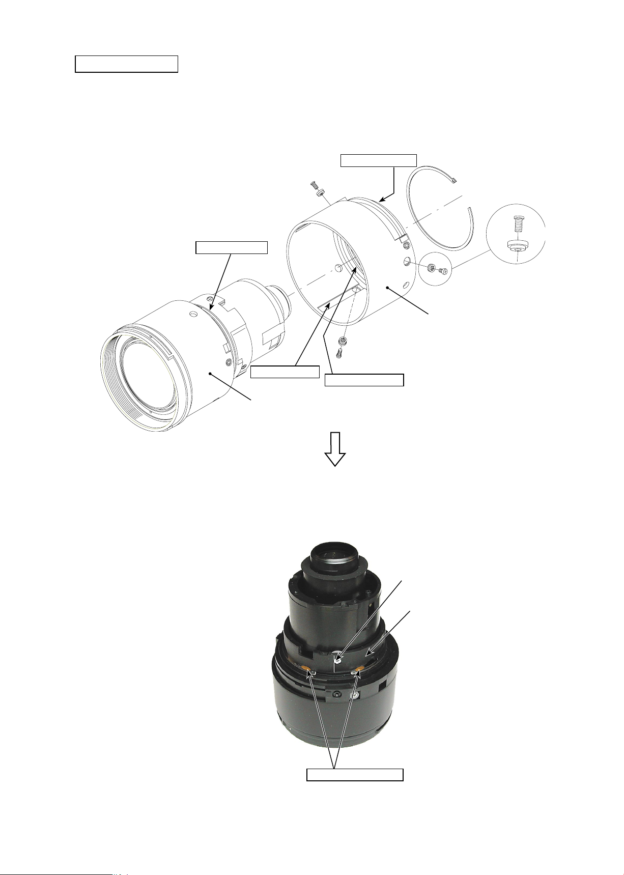
1. Disassembly
INC
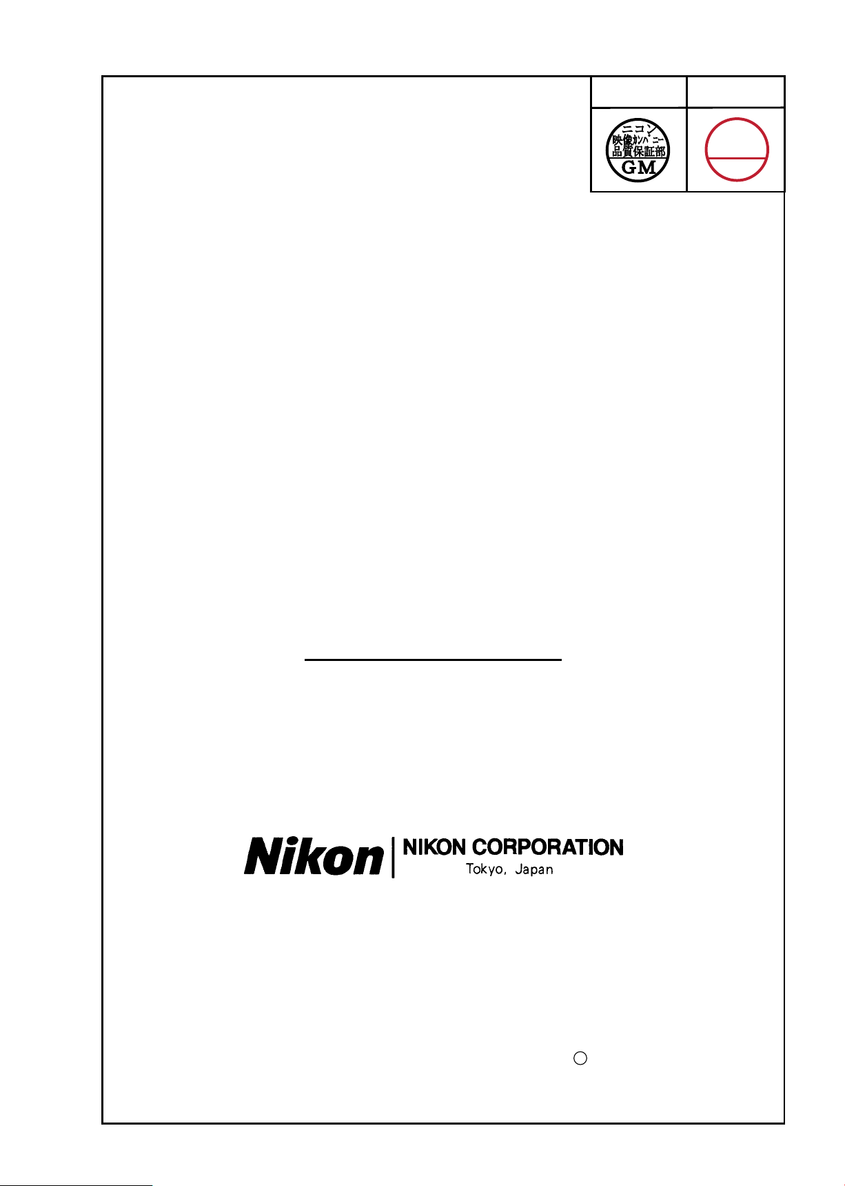
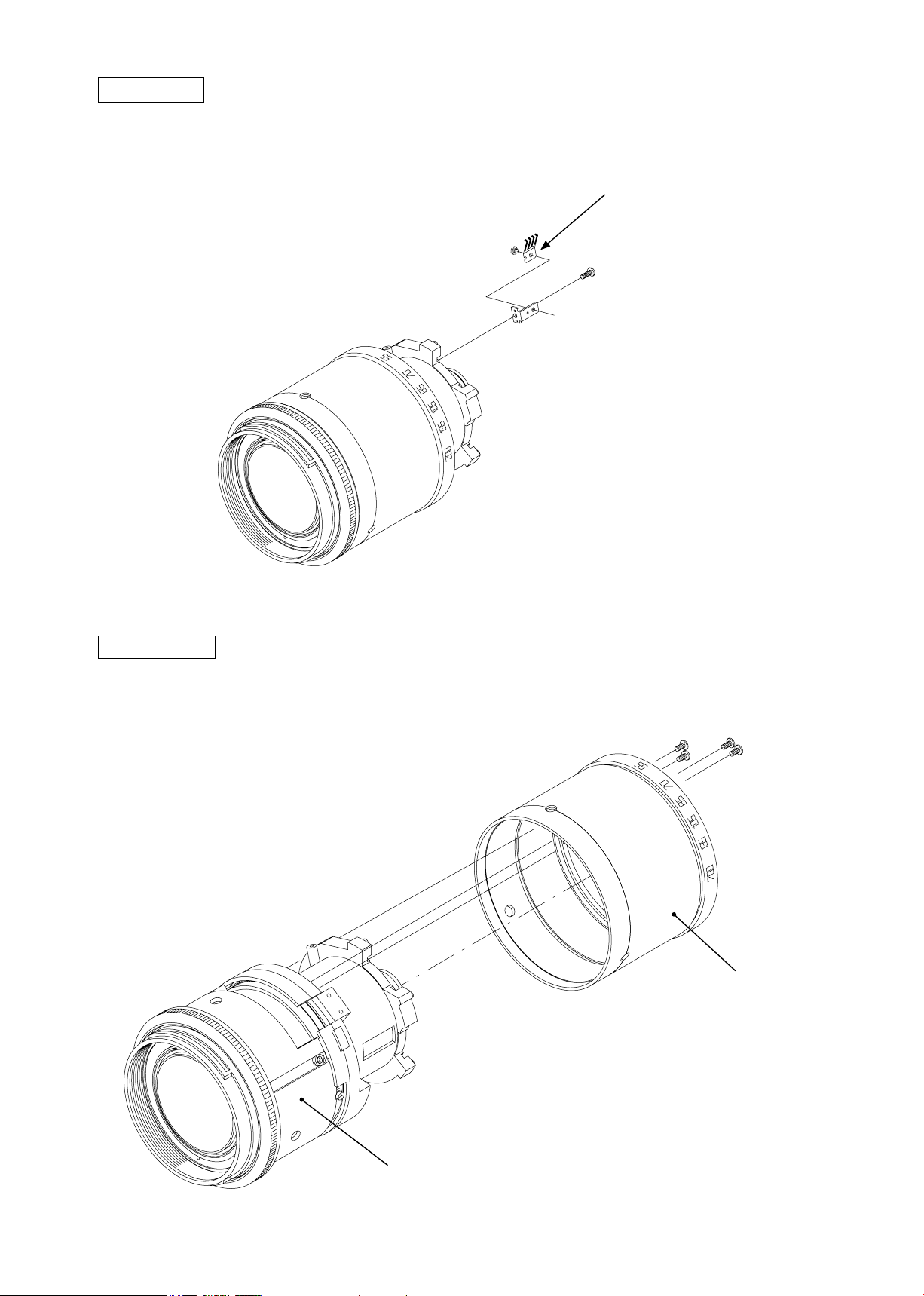
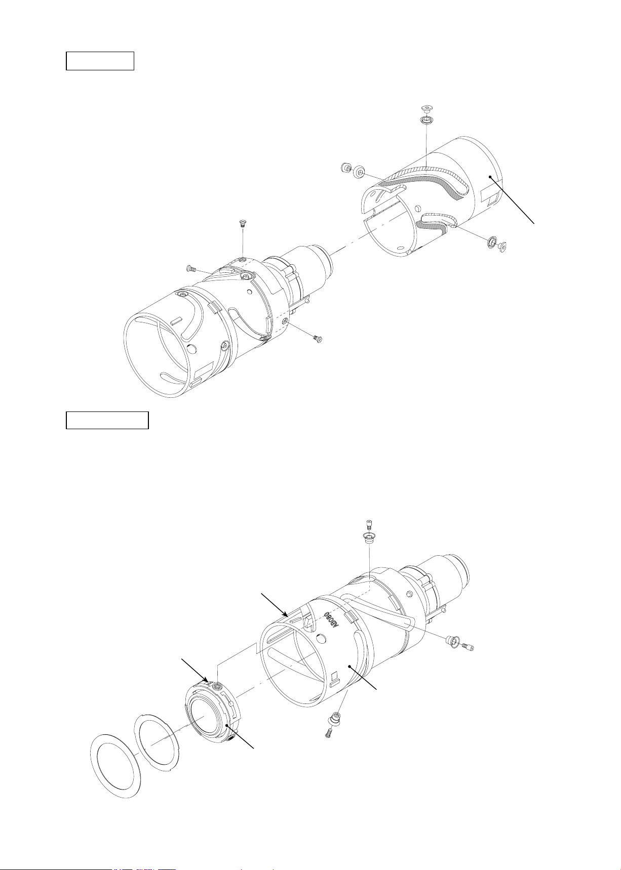
Rear cover ring
Take out 3 screws (#66) of the rear cover ring.
・
Take out 2 screws (#65) of AF contact unit.
・
#65×2
JAA79351-R.3670.A
Rear cover ring
Light-shielding plate / Rubber ring
#66×3
Light-shielding plate
Lens body
- D2・AF-S DX55-200/4-5.6G
JAA79351-R.3670.A
INC
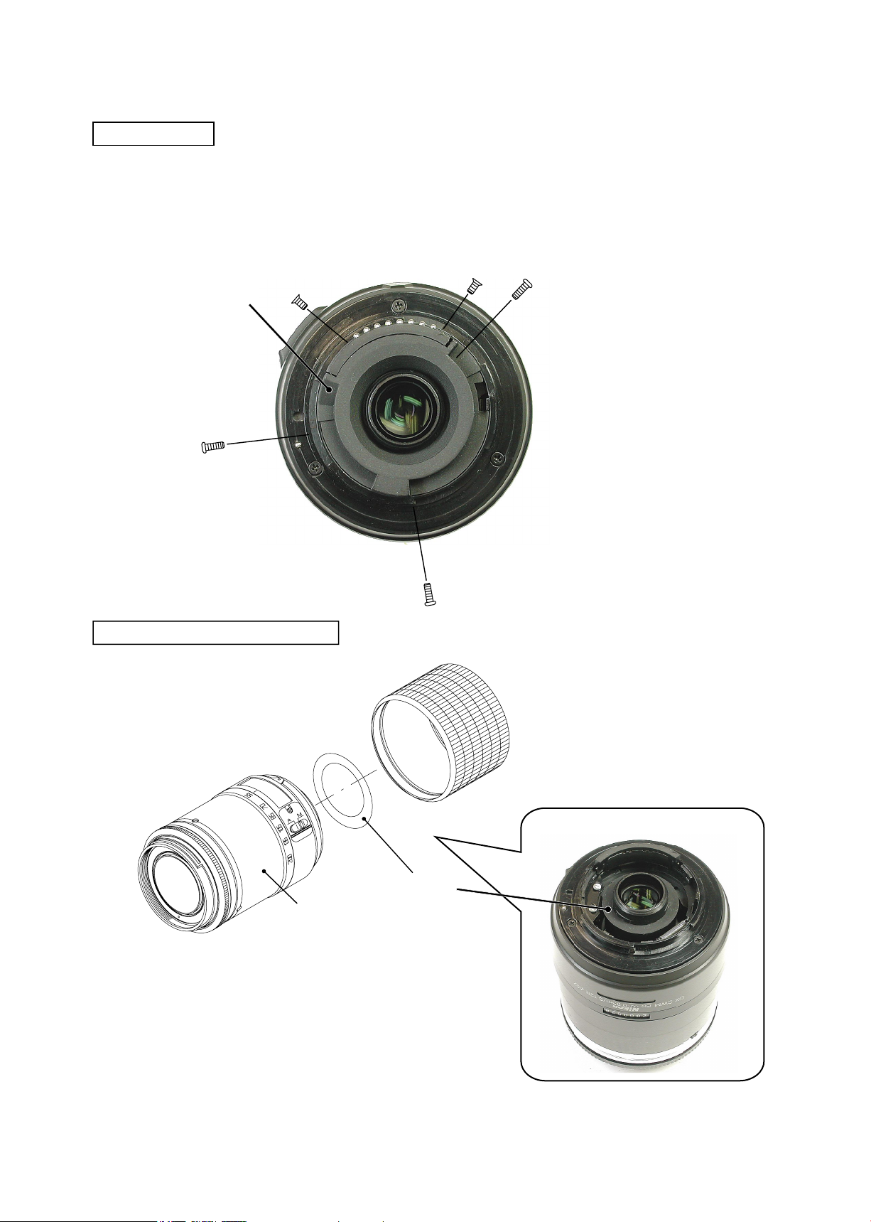
Index ring / Mount unit
Take out 3 screws (#64).
・
Slacken the mount unit a little. Then remove the GND wire (of the main PCB) from the GND terminal (of the
・
mount unit).
Remove the mount and washer (#62) from the lens body.
・
Set the change-SW to A mode.
・
Take out the screw (#59) and the A/M change SW comes off by sliding it slightly in the direction of the arrow.
・
Pass the change SW unit through the hole of the index ring, and remove the index ring.
・
Index ring
Mount unit
#64×3
#62
Aperture coupling lever
Contact socket
#59
Change-SW
Lens body
- D3・AF-S DX55-200/4-5.6G
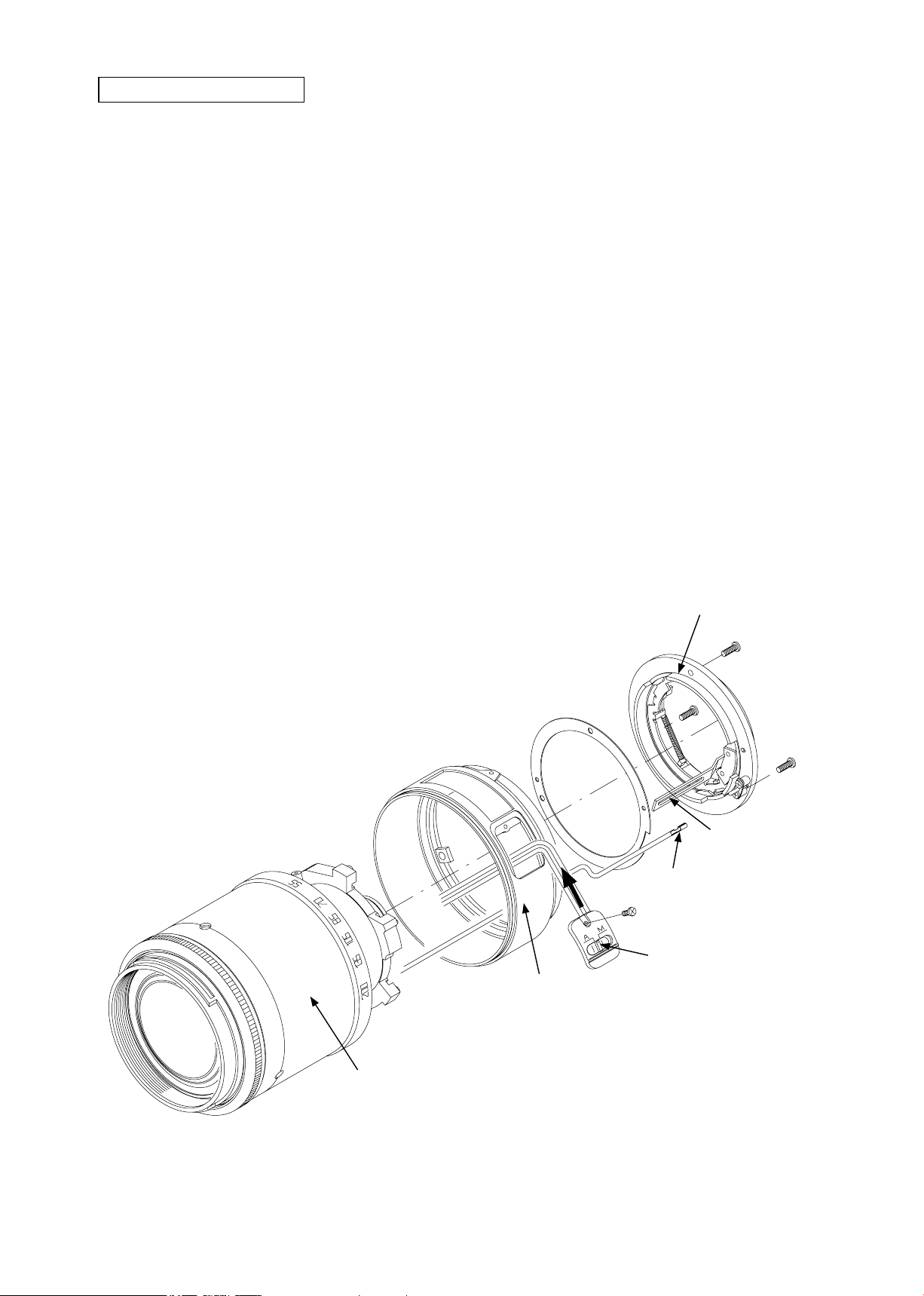
Main PCB
INC
Remove the FPC of the SWM motor from the connector.
・
Disconnect each FPC of the MR sensor, AF contact, and zoom encoder from each connector.
・
Take out 3 screws (#73).
・
Remove the main PCB from the lens body.
・
JAA79351-R.3670.A
MR sensor FPC
SWM unit
AF contact FPC
Screw (#73)×2
Zoom encoder FPC
Red
White
Change SW
SWM FPC
Screw (#73)
Take out the screws (#47-1 and #47-2), and remove the SWM unit.
・
Note: Do NOT touch A part directly with hand.
- D4・AF-S DX55-200/4-5.6G
SWM unit
#47-1
A part
#46-2
#47-2
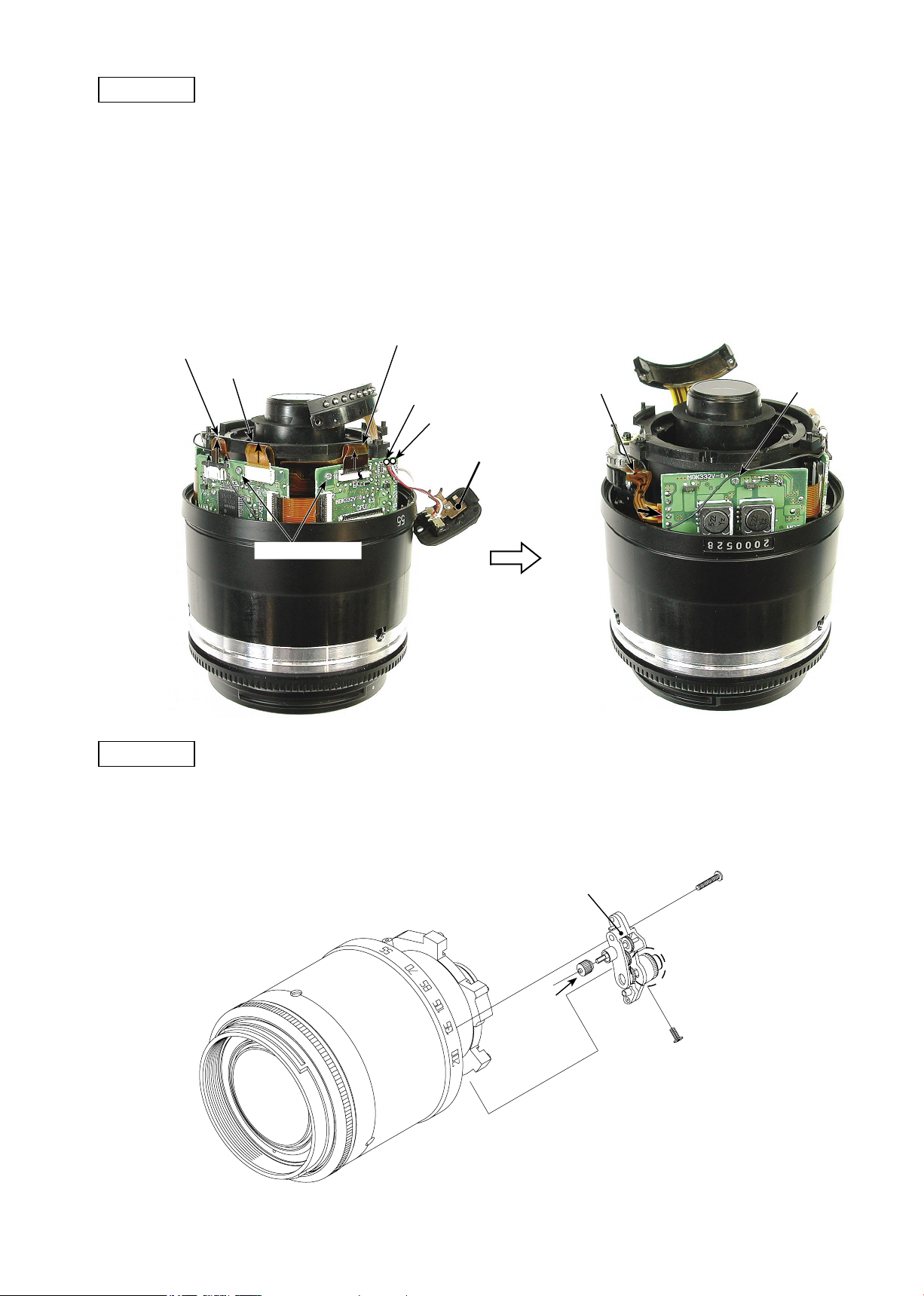
Zoom brush
INC
Take out the screw (#53) to remove the zoom brush.
・
JAA79351-R.3670.A
Zoom brush
#55
#53
#52
Zoom ring
Take out 4 screws (#51) to remove the zoom ring unit.
・
#51×4
Zoom ring unit
Lens body
- D5・AF-S DX55-200/4-5.6G
AF contact unit
INC
Remove the AF contact unit, which is attached with the both-sided adhesive tape.
・
AF contact unit
JAA79351-R.3670.A
MR sensor unit
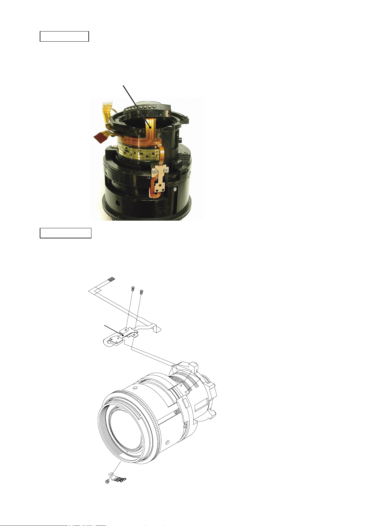
Take out 2 screws (#75) to remove the MR sensor unit.
・
Take out the screw (#39) to remove the focus brush.
・
#75×2
MR sensor unit
#39
Focus brush
- D6・AF-S DX55-200/4-5.6G

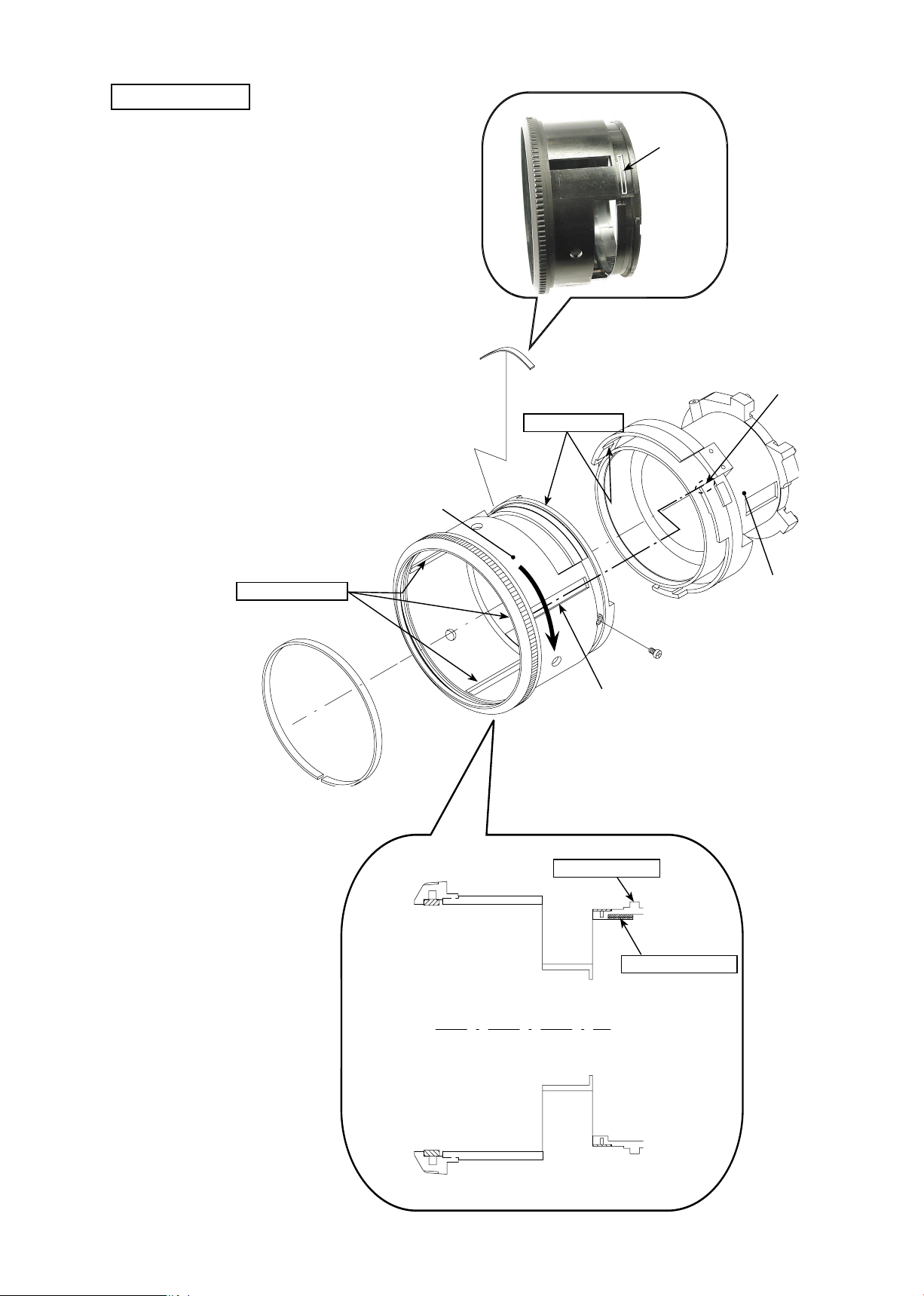
Mid-lens barrel unit
INC
Take out 3 screws (#41) and 3 collars (#40).
・
Take out 4 screws (#45) to remove the mid-lens barrel unit from the lens body.
・
2 keys (#48) come off at the same time.
・
#41
#40
JAA79351-R.3670.A
#48×2
#45×4
Lens body
Mid-lens barrel unit
#40×3
#41×3
- D7・AF-S DX55-200/4-5.6G
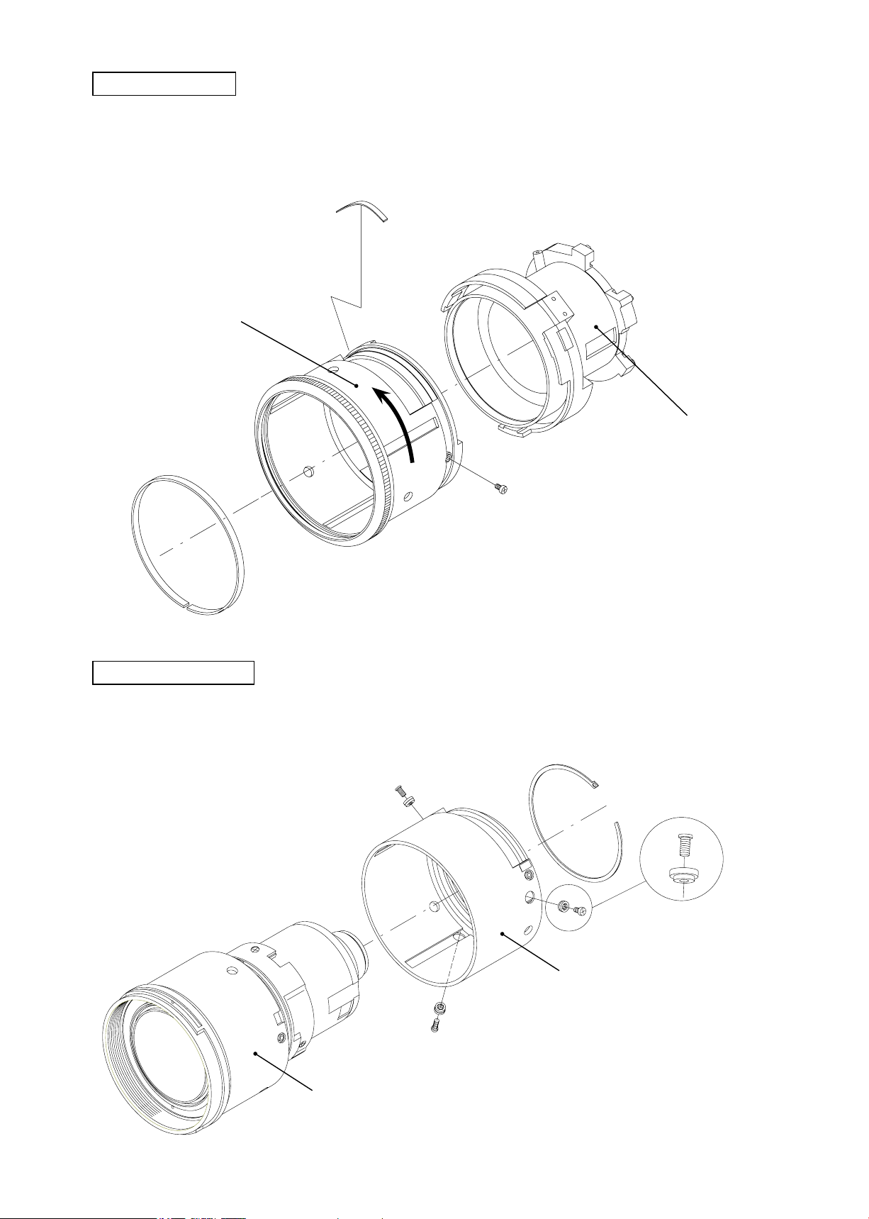
Focus gear ring unit
INC
Remove the stopper screw (#42).
・
Viewed from the object, turn the focus gear ring counterclockwise a little to remove it.
・
The friction spring (#70) comes off.
・
#70
Focus gear ring
JAA79351-R.3670.A
Mid-lens barrel unit
Object side
Focus coupling ring
Take out 3 screws (#34) and 3 collars (#33).
・
Remove the stopper ring (#35) to detach the focus coupling ring.
・
#34×3
#33×3
#42
#35
#34
#33
Focus coupling ring
Lens body
- D8・AF-S DX55-200/4-5.6G
JAA79351-R.3670.A
INC
1st lens group
Turning the 1st lens-group sliding ring and focus ring each in the direction of the arrow, and remove them
・
from the lens body.
1st lens-group sliding
ring
Focus ring
- D9・AF-S DX55-200/4-5.6G
Lens body
Fixed tube
INC
Take out 3 screws (#28).
・
Remove 3 cam-tube guide axles (#31) and 3 cam-tube guide
・
collars (#30).
Remove the xed tube (#29) from the lens body.
・
JAA79351-R.3670.A
#30×3
#31×3
#28×3
2nd lens group
Peel off the sheet (#8).
・
Remove 3 2nd lens-group collars (#20-6) and 3 screws (#20-7).
・
Remove the 2nd lens unit.
・
#29
Reference line
#8
#20-7×3
#20-6×3
Concave portion
Straight tube unit
2nd lens group
#9
- D10・AF-S DX55-200/4-5.6G
Straight tube unit
INC
Remove 3 3rd lens-group collars (#20-4) and 3 screws (#20-5).
・
The 3rd lens group and straight tube unit come off.
・
JAA79351-R.3670.A
#20-5×3
#20-4×3
Concave portion
Straight tube unit
3rd lens group
Removal of 3rd lens group and 4th lens group
Take out 3 screws (#19).
・
#17 and 4th lens group come off.
・
Aperture lever
The washer and spring-
・
washer are assembled in the
screw (#19).
#19×3
3rd lens group
4th lens group
#17
#15×3
#16×3
- D11・AF-S DX55-200/4-5.6G
2. Assembly / Adjustment
AB08
INC
Mounting of 4th lens group on 3rd lens group
JAA79351-R.3670.A
3rd lens group
Straight tube unit
Align the letter of the 4th lens group
with the position of the aperture lever.
#17
#19×3
4th lens group
The washer and spring-
・
washer are assembled in the
screw (#19).
Align the concave portion of the straight tube unit with the position of the aperture lever of the 3rd lens group,
・
and assemble them. Then attach 3 3rd lens-group collars (#20-4) with 3 screws (#20-5).
#20-5×3
#20-4×3
Convex portion
Straight tube unit
Aperture lever
3rd lens group
- A1・ AF-S DX55-200/4-5.6G -
2nd lens group
INC
Align the reference line of the 2nd lens group with the
・
concave portion of the straight tube unit, and assemble
them. Then x with 3 collars (#20-6) and 3 screws
(#20-7).
Reference line
#9
Concave portion
JAA79351-R.3670.A
#20-7×3
#20-6×3
Straight tube unit
2nd lens group
Fixed tube
#8
Align the concave portion of the xed tube (#29) with the position of the aperture lever of the
①
lens body. Then assemble them so that 2nd lens G collars enter into the 3 U-grooves.
Put 3 cam-tube guide axles (#30) and 3 guide collars
②
(#31) through 3 grooves of the xed tube (#29), and
-groove× 3 locations
U
Grease: MZ-800S
#30×3
#31×3
insert them into the concave portions inside of the
lens body. (ref. Pic. 1)
Fix the 3 cam-tube guide collars (#30)
③
with 3 screws (#28).
Apply a little to upper half
around the tube.
Adhesive: EDB0011
#28×3
Vertical groove in the
inner diameter surface
×3 locations
Grease: MZ-800S
2nd lens G collar
Aperture lever
Concave portion inside
of the lens body
Grease: G92KA
Fitting 3 locations
Concave portion
#29
A
As shown "A", lift up #29 a little and insert #30. Then when it
is seated at "B" position, push #29 down into "C" position.
- A2・ AF-S DX55-200/4-5.6G -
#29
#30
Pic. 1
#29
B
C

JAA79351-R.3670.A
INC
1st lens group
Put the 1st lens-G adjusting washer (#3) and the 1st lens-group into the 1st lens-G sliding ring.
①
Attach 3 1st lens-G collars (#6) and 3 screws (#7) to the 1st lens-G sliding ring.
②
Set the straight tube of the lens body to WIDE side.
③
Viewed from the 1st lens group side, place the “PC-30” letters of the focus ring at the position of 10 o'clock,
④
: Newly prepared as RJ
★
by counting the index position of the 1st lens-G sliding ring as 12 o'clock.
Put the focus ring and 1st lens-G sliding ring in the place of Fig.1. Then align the convex portion of the lens
⑤
body with the concave portion of the focus ring to assemble them.
Turn the lens body, which was assembled in⑤ in the direction of the arrow until its convex portion enters in
⑥
the inner groove of the 1st lens-G sliding ring. Then push the lens body and focus ring all the way into the
1st lens-G sliding ring.
Apply to convex portion × locations
and entire circumference surface.
★
Grease:6308/10K
#7
#6
“PC-30”10-o'clock position
Convex portion
Concave portion
Concave portion
Inner groove
1st lens G sliding
ring
Index
1st lens group
#7×3
#6×3
Grease: MZ-800S
Apply to tting part and vertical groove.
Grease: MZ-800S
Apply to cam groove
Focus ring
Lens body
Grease: MZ-800S
2 kinds of convex portions
× 6 locations
Approx. 10 mm
Fig.1
#3
- A3・ AF-S DX55-200/4-5.6G -
JAA79351-R.3670.A
- A4・ AF-S DX55-200/4-5.6G -
Focus coupling ring
Note:
Do NOT pull out the 1st lens group from the lens body while assmbling to keep it from becoming detached from the
grooves, etc of the lens body.
Grease: MZ-800S
Apply to sliding surface with #35.
#35
#34×3
#33×3
#34
#33
Focus coupling ring
Lens body
Grease: MZ-800S
Apply to tting part.
Grease:MZ-800S
Apply to vertical
groove.
Grease: MZ-800S
Apply to tting part.
Adhesive: EDZ4113
Concave portion
Boundary line of concave portion
・
Fix the focus coupling ring retainer (#35) at the below position, and apply the adhesive (EDZ4113) at
2 locations of the below.
INC
JAA79351-R.3670.A
- A5・ AF-S DX55-200/4-5.6G -
Focus gear ring
①
Attach the friction cloth (#36) to the focus gear
ring.
②
Put the friction spring (#70) into the concave
portion of the focus gear ring.
③
Align the center of the vertical groove of the fo-
cus gear ring with the "A" part of the mid-lens
barrel unit, and assemble them. Then turn the
focus gear ring a little in the direction of the ar-
row.
④
Fix the stopper screw (#42).
#42
#36
Object side
#70
Grease: 6308/10K
Ap ply to tt ing
part
A part
Vertical groove
Focus gear ring
Mid-lens barrel unit
Grease: MZ-800S
Vertical groove× 3 locations
★
: Newly prepared as RJ
★
Focus gear ring
Concave
portion
Cross-section view of Focus gear ring
Grease: MZ-800S
Apply to gear
Grease: 6308/10K
Apply to tting part
INC
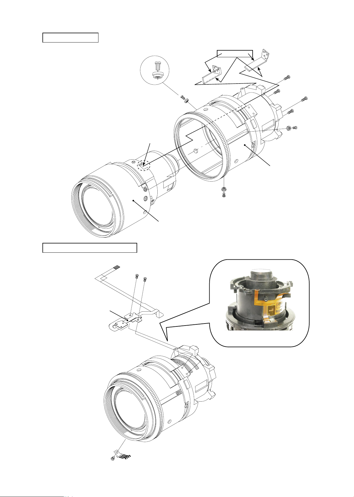
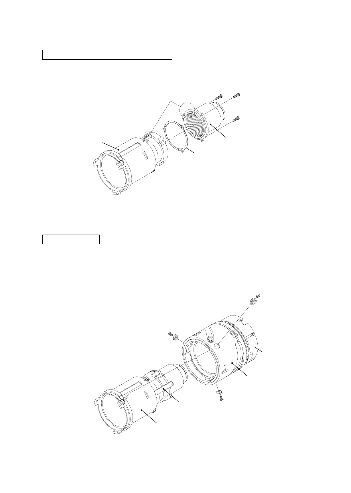
Mid-lens barrel unit
INC
Note) Pass 2 zoom coupling plates
(#48) through the groove of
the mid-lens barrel unit, then
in t o the g r oove of the len s
body. Fix the mid-lens barrel
unit with 4 screws (#45).
Groove of the lens body
#41
#40
Apply to tting part.
Grease: G92KA
#40×3
#41×3
JAA79351-R.3670.A
#48×2
#45×4
Mid-lens barrel unit
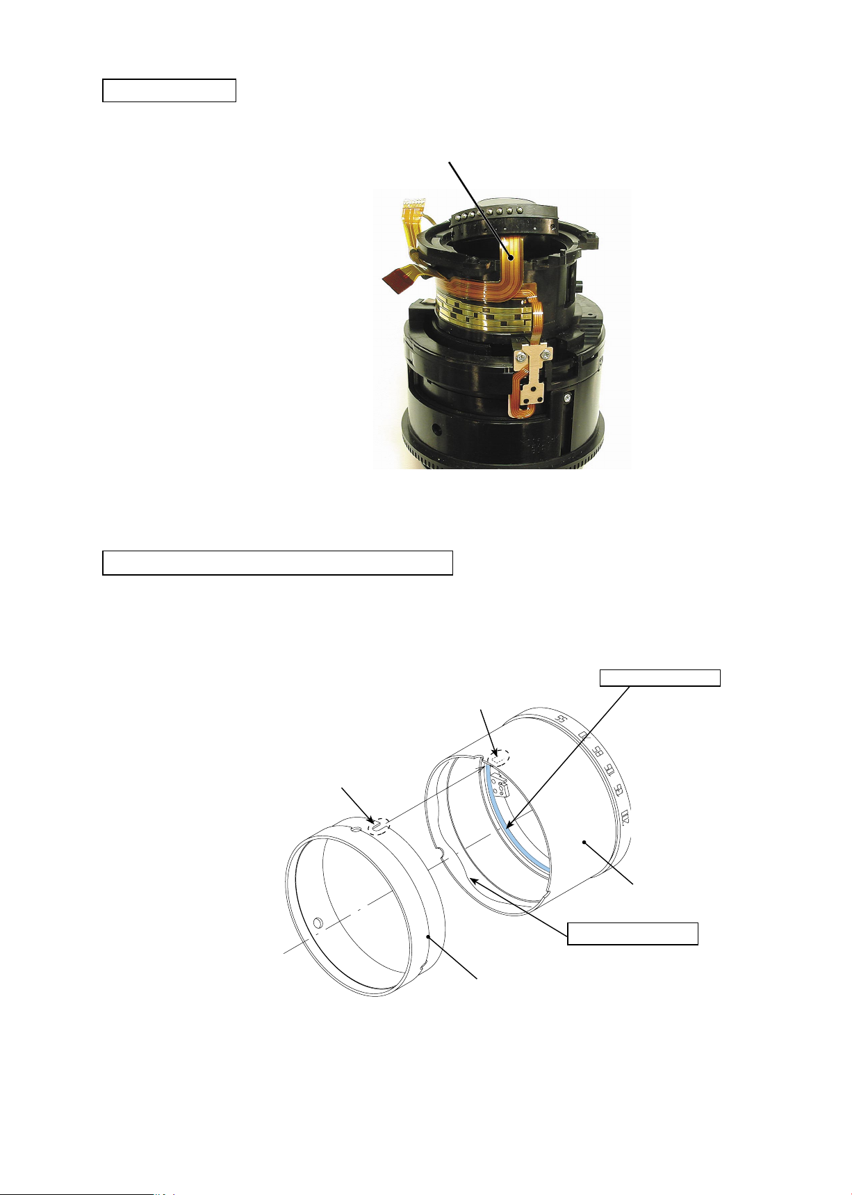
MR sensor unit / Focus brush
MR sensor unit
Lens body
#75×2
FPC attaching position
#39
Focus brush
- A6・ AF-S DX55-200/4-5.6G -
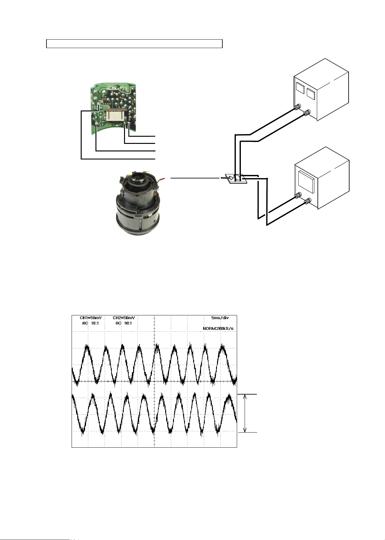
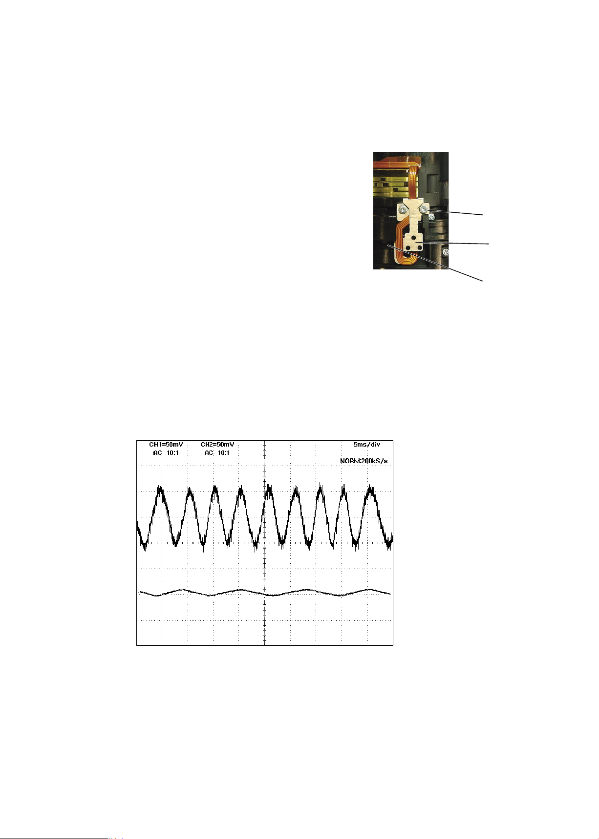
Inspection and adjustment of MR encoder output waveform
INC
Attachment diagram
・
【
】
Self-made tool that is created with
the main PCB of AF-S 24-85
JAA79351-R.3670.A
Rated voltage power-supply
(GND)
( + )
Oscilloscope
Oscilloscope
Rated voltage power-supply
Rated voltage power-supply
How to inspect and adjust:
・
Conrm that the electric current and voltage of the connected rated voltage power-supply are set values, then
①
turn it ON.
Set the oscilloscope, and turn the focus ring manually.
②
(2ch)
(1ch)
(+)
(-)
Self-made tool
Set value
5.0 V
100 mA
Oscilloscope
(2ch type)
Note: The waveform varies according to the rotational speed of the focus ring. So change "Time/Div” setting
accordingly.
CH1
CH2
Fig.1
● Oscilloscope setting
V/Div (ch1) : 50 mV
V/Div (ch2) : 50 mV
Coupling : AC
Time/Div : 5 m Sec
Trigger Mode : NORMAL
Trigger Coupling : AC
Amplitude
Standard:
Note:
Amplitude of all pulses/
waveforms is 70mV or more.
Check the waveform by moving the
focus ring back and forth from the
innity-end to the close-end positions
entirely.
- A7・ AF-S DX55-200/4-5.6G -
In case large waveform-noise (as shown in Fig. 1) is detected, use the FILTER function.
INC
③
How to set FILTER function (e.g. DL1540 manufactured by YOKOGAWA
1. Press the FILTER button.
2. Select “Smooth” of the menu on screen and turn it ON.
In case the amplitude is small, check if there is
⑥
deformation in the MR head. If there is, correct the
deform of the MR head. However, if such correction
is impossible or no deformation is detected, replace
the MR sensor unit. (Fig.2)
JAA79351-R.3670.A
)
#75×2
Note: When adjustments are made,
magnetic surface and MR head from touching the
magnetized driver bit. Otherwise, the magnetic
data may be damaged.
Ref.
<
● As shown in Fig. 3,
>
if the amplitude of only either CH1 or CH2 is small, one of the 2 screws (#75) may be
loosened, so check for it. If this is not the case, the MR head may malfunction, so replace the MR sensor
unit and make a readjustment.
prevent the
MR head
Magnetic
surface
Fig.2
CH1
CH2
Fig. 3
- A8・ AF-S DX55-200/4-5.6G -
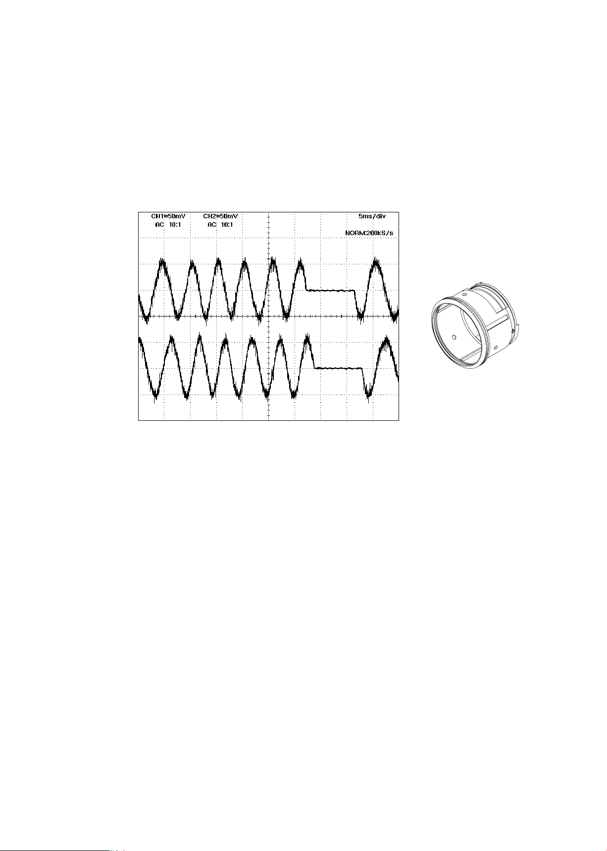
JAA79351-R.3670.A
INC
As shown in Fig. 4,
●
magnetic data of the tape may be damaged. So replace the focus gear ring unit and make a readjustment.
Replacing only the magnetic surface is impossible.
CH1
if the amplitude partially drops between the innity and the close-distance, the
Focus gear ring unit
CH2
⑤
Turn off the rated voltage power-supply.
Fig.4
- A9・ AF-S DX55-200/4-5.6G -
JAA79351-R.3670.A
- A10 ・ AF-S DX55-200/4-5.6G -
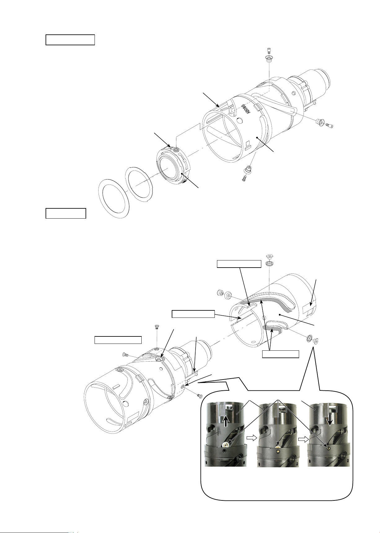
AF contact unit
Adhesion of Zoom ring and Zoom reinforcement ring
AF contact unit
・
By using the both-sided adhesive
tape of the AF contact unit,
attach the AF contact unit to the
lens body.
Grease: G92KA
Apply to the overall circumferential
convex portion
Adhesive: C-8008B
Apply to the circumferential joining part with the
zoom reinforcement ring.
Zoom reinforcement ring
Zoom ring
・
Enter the inner convex portion of the zoom ring into
the U-groove of the
zoom reinforcement ring to assemble them. Then apply the adhesive.
Inner convex portion
U-groove
INC
 Loading...