

Page 1

EN - Instructions and warnings for
installation and use
IT - Istruzioni ed avvertenze per
l’installazione e l’uso
FR - Instructions et avertissements
pour l’installation et l’utilisation
ES - Instrucciones y advertencias
para la instalación y el uso
DE - Installierungs-und Gebrauchs-
anleitungen und Hinweise
PL - Instrukcje i ostrzeżenia do
instalacji i użytkowania
NL - Aanwijzingen en aanbevelingen
voor installatie en gebruik
NiceOne
Receiver
OXI family
OX2 family
Europe: 0682
Page 2

EN- Integration to manual
IT - Integrazione al manuale
FR - Addenda au guide
ES - Integración del manual
DE- VervollstŠndigung des Handbuchs
PL - Uzupełnienie do instrukcji
NL - Aanvulling op de handleiding
ENGLISH - List of commands available with OXI receiver and transmitters memorised in “Extended Mode II”:
Output
1
2
3
4
5
6
7
8
9
10
11
12
13
14
15
Command
Step by step
Partial opening 1
Open
Close
Stop
Apartment block Step by Step
Step by Step high priority
Partial open 2
Partial open 3
Open and block automation
Close and block automation
Block automation
Release automation
Courtesy light timer on
Courtesy light on-off
Description
“S.S.” (Step by Step) command
“Partial opening 1” command
“Open” command
“Close” command
Stops manoeuvre
Apartment block control
Run and Robus 400/600/1000: Gives command even when automation is blocked or commands are in progress
Soon: Gives command even when automation is blocked
“Partial opening 2” command (programmable with Oview)
“Partial opening 3” command (programmable with Oview)
It causes an opening manoeuvre, after which the automation is blocked; the control unit accepts no further commands with the exception of “Step by
step high priority”, “Release” automation and (from Oview only) the commands “Release and close” and “Release and open”
It causes a closure manoeuvre, after which the automation is blocked; the control unit accepts no further commands with the exception of “Step by
step high priority”, “Release” automation and (from Oview only ) the commands “Release and close” and “Release and open”
It causes the manoeuvre to stop and the automation to block; the control unit accepts no further commands with the exception of “Step by step high
priority”, “Release” au to mation and (from Oview only ) the commands “Release and close” and “Release and open”.
It causes the automation to be released and normal operation to resume
The Courtesy light comes on with timed turning off
The Courtesy light turns on and off in step-by-step mode
ITALIANO - Elenco dei comandi disponibili con ricevitore OXI e trasmettitori memorizzati in “Modo II esteso”:
Uscita
1
2
3
4
5
6
7
8
9
10
11
12
13
14
15
Comando
Passo-Passo
Apertura parziale 1
Apre
Chiude
Stop
Passo-Passo Condominiale
Passo-Passo alta priorità
Apre parziale 2
Apre parziale 3
Apre e Blocca automazione
Chiude e Blocca automazione
Blocca automazione
Sblocca automazione
On Timer Luce di Cortesia
On-Off Luce di Cortesia
Descrizione
Comando “P.P.” (Passo-Passo)
Comando “Apertura parziale 1”
Comando “Apre”
Comando “Chiude”
Arresta la manovra
Comando in modalità Condominiale
Run e Robus 400/600/1000: Comanda anche con automazione bloccata o comandi attivi - Soon: Comanda anche con automazione bloccata
Comando “Apertura parziale 2” (programmabile con Oview)
Comando “Apertura parziale 3” (programmabile con Oview)
Provoca una manovra di apertura e al termine di questa il blocco dell’automazione; la centrale non accetta nessun altro comando ad eccezione di
“Passo passo alta priorità”, “Sblocca” automazione oppure (solo da Oview) i comandi: “Sblocca e chiude” e “Sblocca e apre”
Provoca una manovra di chiusura e al termine di questa il blocco dell’automazione; la centrale non accetta nessun altro comando ad eccezione di
“Passo passo alta priorità”, “Sblocca” automazione oppure (solo da Oview) i comandi: “Sblocca e chiude” e “Sblocca e apre”
Provoca una fermata della manovra ed il blocco dell’automazione; la centrale non accetta nessun altro comando ad eccezione di “Passo passo alta
priorità”, “Sblocca” automazione oppure (solo da Oview) i comandi: “Sblocca e chiude” e “Sblocca e apre”
Provoca lo sblocco dell’automazione ed il ripristino del normale funzionamento
Si accende l'uscita Luce di cortesia con spegnimento temporizzato
Si accende e spegne l'uscita Luce di cortesia in modalità passo-passo
FRANÇAIS - Liste des commandes disponibles avec récepteur OXI et émetteurs mémorisés en « Mode II étendu » :
Sortie
1
2
3
4
5
6
7
8
9
10
11
12
13
14
15
Commande
Pas à pas
Ouverture partielle 1
Ouverture
Fermeture
Stop
Pas à pas collectif
Pas à pas haute priorité
Ouverture partielle 2
Ouverture partielle 3
Ouverture et blocage de
l’automatisme
Fermeture et blocage de
l’automatisme
Blocage de l’automatisme
Déblocage de l’automatisme
Activation temporisateur
clairage automatique
Marche - Arrêt éclairage
automatique
Description
Commande « PP » (pas à pas)
Commande « Ouverture partielle 1 »
Commande « Ouverture »
Commande « Fermeture »
Arrête la manœuvre
Commande en modalité Fonctionnement collectif
Run et Robus 400/600/1000: Commande aussi avec automatisme bloqué ou commandes actives - Soon: Commande aussi avec automatisme bloqué
Commande « Ouverture partielle 2 » (programmable avec Oview)
Commande « Ouverture partielle 3 » (programmable avec Oview)
Provoque une manœuvre d’ouverture et à la fin de celle-ci le blocage de l’automatisme ; la logique n’accepte aucune autre commande à l’exception
de « Pas à pas haute priorité », « Déblocage de l’automatisme » ou (uniquement avec Oview) les commandes : « Déblocage et fermeture » et « Déblocage et ouverture »
Provoque une manœuvre de fermeture et à la fin de l’automatisme ; la logique n’accepte aucune autre commande à l’exception de « Pas à pas haute
priorité », « Dé blocage de l’automatisme » ou (uniquement avec Oview) les commandes : « Déblocage et fermeture » et « Déblocage et ouverture »
Provoque un arrêt de la manœuvre et le blocage de l’automa tisme ; la logique n’accepte aucune autre commande à l’ex ception de « Pas à pas haute
priorité », « Déblocage de l’au tomatisme » ou (uniquement avec Oview) les commandes : « Déblocage et fermeture » et « Déblocage et ouverture »
Provoque le déblocage de l’automatisme et le rétablissement du fonctionnement normal
Allumage de la sortie Éclairage automatique avec extinction temporisée
Allumage et extinction de la sortie Éclairage automatique en modalité pas à pas
Page 3

IST314.4858 Rev. 00 – 01-10-2009
ESPAÑOL - Lista de los mandos disponibles con receptor OXI y transmisores memorizados en “Modo II amplio”:
Salida
1
2
3
4
5
6
7
8
9
10
11
12
13
14
15
Mando
Paso a Paso
Apertura parcial 1
Abrir
Cerrar
Stop
Paso a Paso Comunitario
Paso a Paso prioridad alta
Abrir parcial 2
Abrir parcial 3
Abrir y Bloquear automatización
Cerrar y Bloquear
automatización
Bloquear automatización
Desbloquear automatización
On Timer Luz de cortesía
On-Off Luz de cortesía
Descripción
Mando “P.P.” (Paso a Paso)
Mando "Apertura parcial 1"
Mando “Abrir”
Mando “Cerrar”
Detiene el movimiento
Mando en modalidad Comunitaria
Run y Robus 400/600/1000: Acciona incluso con la automatización bloqueada o con los mandos activos
Soon: Acciona incluso con la automatización bloqueada
Mando “Apertura parcial 2” (programable con Oview)
Mando “Apertura parcial 3” (programable con Oview)
Provoca un movimiento de apertura y al final de éste provoca el bloqueo del automatismo; la central no acepta ningún otro mando salvo “Paso a paso
prioridad alta”, “Desbloquear” automación o bien (sólo desde Oview) los mandos: “Desbloquear y cerrar” y “Desbloquear y abrir”
Provoca un movimiento de cierre y al final de éste provoca el bloqueo del automatismo; la central no acepta ningún otro mando salvo “Paso a paso
prioridad alta”, “Desbloquear” automación o bien (sólo desde Oview) los mandos: “Desbloquear y cerrar” y “Desbloquear y abrir”
Provoca una parada del movimiento y el bloqueo del automatismo; la central no acepta ningún otro mando salvo “Paso a paso prioridad alta”, “Desbloquear” automación o bien (sólo desde Oview) los mandos: “Desbloquear y cerrar” y “Desbloquear y abrir”.
Provoca el desbloqueo del automatismo y el restablecimiento del funcionamiento normal
Se enciende la salida Luz de cortesía con apagado temporizado
Se enciende y apaga la salida Luz de cortesía en modalidad paso a paso
DEUTSCH - Liste der verfügbaren Steuerungen mit Empfänger OXI und Sender, die im “erweiterten Modus II” gespeichert sind:
Ausgang
1
2
3
4
5
6
7
8
9
10
11
12
13
14
15
Steuerung
Schrittbetrieb
Teilöffnung 1
Öffnen
Schließt
Stopp
Schrittbetrieb Wohnblock
Schrittbetrieb Hohe Priorität
Teilöffnung 2
Teilöffnung 3
Öffnen und sperren
Automatisierung
Schließt und Blockiert die
Automatisierung
Blockiert die Automatisierung
Löst die Automatisierung
On Timer zusätzliche Beleuchtung
On-Off zusätzliche Beleuchtung
Beschreibung
Befehl “P.P.” (Schrittbetrieb)
Steuerung “Teilöffnung 1”
Befehl “Öffnet”
Befehl “Schließt”
Stoppt die Bewegung
Steuerung im Wohnblockmodus
Run und Robus 400/600/1000: Steuert auch bei blockierter Automatisierung oder aktive Steuerungen - Soon: Steuert auch bei blockierter Automatisierung
Steuerung “Teilöffnung 2” (mit Oview programmierbar)
Steuerung “Teilöffnung 3” (mit Oview programmierbar)
Ruft eine Öffnungsbewegung hervor und am Ende dieser die Blockierung der Automatisierung; die Steuerung akzeptiert keine andere Steuerung,
außer “Schrittbetrieb hohe Priorität”, “Lösen” Automatisierung oder (nur aus Oview) der Steuerungen: “Löst und schließt” und “Löst und öffnet”
Ruft eine Schließbewegung hervor und am Ende dieser die Blockierung der Automatisierung; die Steuerung akzeptiert keine andere Steuerung, außer
“Schrittbetrieb hohe Priorität”, “Lösen” Automatisierung oder (nur aus Oview) der Steuerungen: “Löst und schließt” und “Löst und öffnet”
Ruft einen Bewegungsstopp hervor und am Ende dieser die Blockierung der Automatisierung; die Steuerung ak zeptiert keine andere Steuerung,
außer “Schrittbetrieb ho he Priorität”, “Lösen” Automatisierung oder (nur aus Ovi ew) der Steuerungen: “Löst und schließt” und “Löst und öffnet”
Ruft die Blockierung der Automatisierung und die Wiederherstellung des normalen Betriebs hervor
Der Ausgang zusätzliche Beleuchtung mit zeitgeregelter Abschaltung wird erleuchtet
Der Ausgang zusätzliche Beleuchtung im Schrittbetrieb wird erleuchtet und ausgeschaltet
POLSKI - Wykaz poleceń dostępnych z zastosowaniem odbiornika OXI i nadajników wczytanych w “Trybie II poszerzonym”:
Wyjście
1
2
3
4
5
6
7
8
9
10
11
12
13
14
15
Polecenie
Krok po Kroku
Otwarcie częściowe 1
Otwarcie
Zamknięcie
Stop
Krok po kroku w bloku mieszkalnym
Krok po kroku z dużym priorytetem
Otwarcie częściowe 2
Otwarcie częściowe 3
Otwarcie i Zablokowanie
automatyki
Zamknięcie i Zablokowanie
automatyki
Zablokowanie automatyki
Odblokowanie automatyki
Włączenie timera światełka
nocnegon
Włączenie-Wyłączenie
światełka nocnego
Opis
Polecenie “K.K.” (Krok po kroku)
Polecenie “Otwarcie częściowe 12
Polecenie “Otwarcie”
Polecenie “Zamknięcie”
Zatrzymanie manewru
Działanie w trybie “bloku mieszkalnego”
Run i Robus 600/1000: Steruje również w przypadku zablokowania automatyki lub uaktywnienia poleceń
Soon: Steruje również w przypadku zablokowania automatyki
Polecenie “Otwarcie częściowe 2” (programowalne z pomocą Oview)
Polecenie “Otwarcie częściowe 3” (programowalne z pomocą Oview)
Powoduje wykonanie manewru otwarcia a po jego za koń c zeniu zablokowanie automatyki; centrala nie akceptuje żadne go innego polecenia za
wyjątkiem “Krok po kroku z du żym pri orytetem”, “Odblokuj” lub (tylko z Oview) nastę pujące po le cenia: “Odblokowanie i zamknięcie” i “Odblokowanie i otwarcie”
Powoduje wykonanie manewru zamknięcia a po jego zakończeniu zablokowanie automatyki; centrala nie akceptuje żadnego innego polecenia za
wyjątkiem “Krok po kroku z dużym priorytetem”, “Odblokuj” lub (tylko z Oview) na stępujące polecenia: “Odblokowanie i zamknięcie” i “Od blo kowanie i otwarcie”
Powoduje zatrzymanie manewru i zablokowanie automatyki; centrala nie akceptuje żadnego innego polecenia za wyjątkiem “Krok po kroku z dużym
priorytetem”, “Odblokuj” lub (tylko z Oview) następujące polecenia: “Odblokowanie i zamknięcie” i “Odblokowanie i otwarcie”
Powoduje odblokowanie automatu i przywrócenie zwy kłego funkcjonowania
Włącza się wyjście “światełko nocne”, którego wyłączanie jest regulowane timerem
Wyjście “światełko nocne” włącza się i wyłącza w trybie “krok po kroku”
NEDERLANDS - Lijst van instructies die beschikbaar zijn met de ontvanger OXI en zenders die zijn opgeslagen in “Modus II uitgebreid”:
Uitgang
1
2
3
4
5
6
7
8
9
10
11
12
13
14
15
Instructie
Stap-voor-stap
Gedeeltelijke opening 1
Open
Sluit
Stop
Stap-voor-stap woonblok
Stap-voor-stap hoge prioriteit
Open gedeeltelijk 2
Open gedeeltelijk 3
Open en blokkeer
Sluit en blokkeer automatisering
Blokeer automatisering
Deblokkeer automatisering
On Timer gebruikerslicht
On-Off gebruikerslicht
Beschrijving
Instructie “P.P.” (Stap-voor-stap)
Instructie “Gedeeltelijke opening 1”
Instructie “Open”
Instructie “Sluit”
Stop de manoeuvre
Instructie in modus Woonblok
Run en Robus 400/600/1000: stuurt ook aan bij geblokkeerde automatisering of actieve instructies - Soon: stuurt ook aan bij geblokkeerde automatisering
Instructie “Open gedeeltelijk 2” (programmeerbaar met Oview)
Instructie “Open gedeeltelijk 3” (programmeerbaar met Oview)
Veroorzaakt een openingsmanoeuvre en na afloop daarvan de blokkering van de automatisering; de besturingseenheid accepteert geen enkele andere instructie met uitzondering van “Stap-voor-stap hoge prioriteit”, “Deblokkeer automatisering” of (alleen vanaf Oview) de instructies: “Deblokkeer en
sluit” en “Deblokkeer en open”
Veroorzaakt een sluitmanoeuvre en na afloop daarvan de blokkering van de automatisering; de besturingseenheid accepteert geen enkele andere
instructie met uitzondering van “Stap-voor-stap hoge prioriteit”, “Deblokkeer automatisering” of (alleen vanaf Oview) de instructies: “Deblokkeer en
sluit” en “Deblokkeer en open”
Veroorzaakt een stop van de manoeuvre en de blokkering van de automatisering; de besturingseenheid accepteert geen enkele andere instructie met
uitzondering van “Stap-voor-stap hoge prioriteit”, “Deblokkeer automatisering” of (alleen vanaf Oview) de instructies: “Deblokkeer en sluit” en
“Deblokkeer en open”.
Veroorzaakt de deblokkering van de automatisering en de hervatting van de normale werking
De uitgang Gebruikerslicht gaat aan, met tijdgeprogrammeerde uitschakeling
De uitgang Gebruikerslicht gaat aan en uit, in de modus Stap-voor-stap
Page 4
2
EN
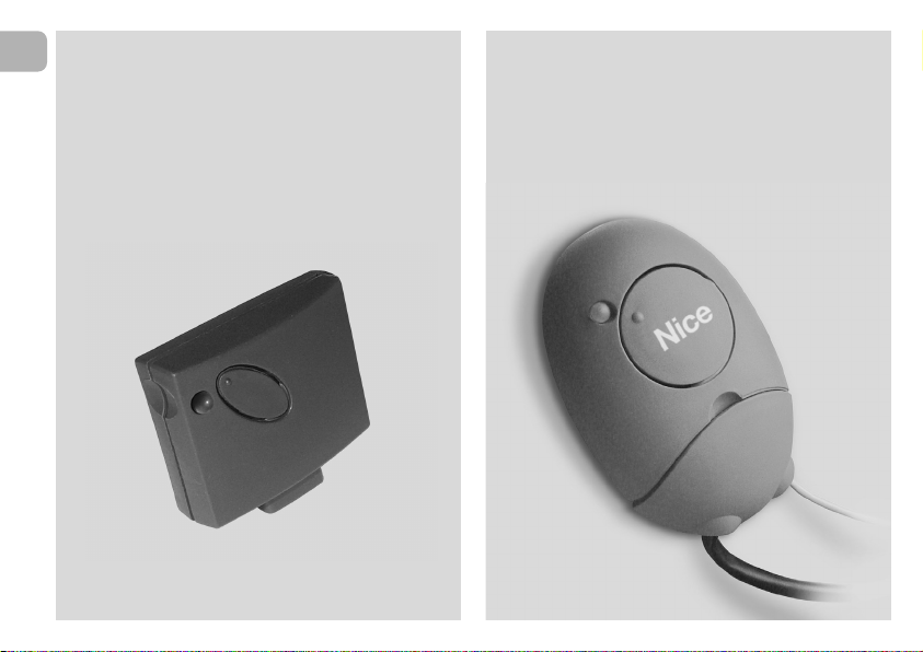
EN – Models with “SM” type connection
IT – Modelli con connessione a innesto “SM”
FR – Modèles avec connecteur embrochable «SM»
ES – Modelos con conexión con conector “SM”
DE – Modelle mit Steckverbindung “SM”
PL – Modele z połączeniem za pomocą złącza
typu “SM”
NL – Modellen met steekconnector “SM”
EN – Models with universal type connection
IT – Modelli con connessione universale
FR – Modèles avec connecteur universel
ES – Modelos con conexión universal
DE – Modelle mit Universalverbindung
PL – Modele z połączeniem uniwersalnym
NL – Modellen met universele aansluiting
Page 5

ENGLISH
Original instructions
1 – PRODUCT DESCRIPTION AND
INTENDED USE
This receiver is part of the series “NiceOne” produced by Nice
spa. The receivers in this series are destined for use on the
control units fitted on systems for the automation of gates,
garage doors and road barriers. Any use other than as
specified herein is to be considered improper and is
strictly prohibited! The manufacturer denies all liability for
damage deriving from improper use of the product and
use other than as specified in this manual.
Various models are available, with the specifications as stated
in the table below.
1.1 – The “NiceOpera” system
The receivers in the series NiceOne are part of the “NiceOpera” system. This system has been designed to simplify
the programming phases, use and maintenance of the de vices normally used in automation systems. The system comprises various software and hardware devices capable of
intercommunicating via radio, by means of the “O-Code”
encoding system or a “physical” connection via cable.
The main devices that make up the NiceOpera system are:
– NiceOne transmitters;
– NiceOne receivers;
– O-box programming unit;
– Control units and gearmotors with “T4 Bus”;
– O-View programmer for devices with “T4 Bus”.
IMPORTANT – For further details on all functions of the
NiceOpera system and interdependency of the various
devices in the system, refer to the general manual “NiceOpera System Book”, also available on the Internet site
www.niceforyou.com.
EN
Mod. Frequency Function Connection
OXI 433.92 MHz Receiver Connector type
OXIFM 868.46 MHz Receiver Connector type
OXIT 433.92 MHz Receiver-transmitter Connector type
OXITFM 868.46 MHz Receiver-transmitter Connector type
OX2 433.92 MHz Receiver with 6-core cable
OX2FM 868.46 MHz Receiver with 6-core cable
OX2T 433.92 MHz Receiver-transmitter with 6-core cable
OX2TFM 868.46 MHz Receiver-transmitter with 6-core cable
Notes to table:
– The frequencies 433.92
MHz and 868.46 MHz are
not compatible.
– The letter “T” in the model
name indicates a receiver with
built-in transmitter.
3
Page 6

4
EN
2 – FUNCTIONAL PRODUCT
SPECIFICATIONS
• For all models
– The receiver manages “O-Code” radio encoding with vari-
able code (rolling-code), which enables use of all the new
functions in the NiceOpera system.
The receiver is compatible also with “FloR”, “TTS”, “Smilo”
and “Flo” encoding systems. However, in this case some of
the exclusive NiceOpera system functions described in
this manual cannot be used.
– The receiver has a capacity of 1024 spaces in which to
memorise transmitters. If the transmitter is memorised in
“Mode I”, all the relative keys
will occupy 1 memory alloca-
tion; otherwise if memorised in “Mode II”, each memorised
key will occupy 1 memory allocation (for memorisation pro-
cedures, see below in this manual).
– Each receiver has its own identification number
called a
“Certificate”.
This number enables access to a series of operations, such
as: Memorisation of new transmitters without the need for
direct intervention on the receiver and use of the O-View
unit, by means of the “T4 Bus” connection.
The sealed coupon in the product pack contains the sheet
with the certificate number of this receiver. Caution! – this
coupon must be kept in a safe place as it enables access to
data stored in the receiver, unless further protection measures are adopted, such as the use of a security password.
• For models with “SM” type connection
– These models can be used exclusively with the control units
fitted with an “SM” type connection (fig. 1). Note – to identify
compatible control units, refer to the Nice product catalogue.
– These models automatically recognise the characteristics of
the control unit to which they are connected and the receiver self-installs as follows.
• If the control unit manages the “T4 Bus
”, the receiver
provides up to 15 different commands.
• If the control unit does not manage the “T4 Bus
”, the
receiver provides up to 4 different command channels.
Caution! – In both cases the number and variety of the
commands available depend on the type and model of control unit used. The “Table of commands” of each control unit
is provided in the instruction manual of the relative control
unit.
• For models with universal type connection
– These models operate with 2 voltage-free contact relays
and therefore can be used with any type of control unit.
• For models with “T” in the model name
– These models are equipped with a “Repeater” function (see
below in this manual) which enables an increase in the trans-
mission range of the transmitters. They also enable “wireless”
communication with the O-Box programming unit.
Page 7

3 – PRODUCT INSTALLATION
• For models with “SM” type connection
These models are connected to the control unit by inserting
the connector in the relative control unit connector (fig. 1).
Caution! – Before connecting or removing the receiver,
disconnect the control unit from the power supply.
The aerial supplied must also be installed, connecting it to the
specific terminals on the control unit.
• For models with universal type connection
––– Power supply selection –––
These models are connected to the control unit by means of a
6-core cable. Before connecting the cable, select the type of
power supply required, leaving or removing the electric jumper
as necessary (fig. 2-a) as follows:
1
– Jumper NOT inserted
(voltage limits: 18 ÷ 28 V)
– Jumper INSERTED
(voltage limits: 10 ÷ 18 V)
2
a
= 24 V ac/dc
EN
= 12 V ac/dc
IT
5
Page 8

6
EN
––– Electrical connections –––
Connect the 6 wires of the receiver cable to the relative terminals of the control unit as follows (fig. 3):
•Redand Black = POWER SUPPLY
(red = Positive, black = Negative. In AC this is not important).
• White and White = RELAY 1 OUTPUT
(voltage-free contact of a normally open relay).
• Purple and Purple = RELAY 2 OUTPUT
(voltage-free contact of a normally open relay).
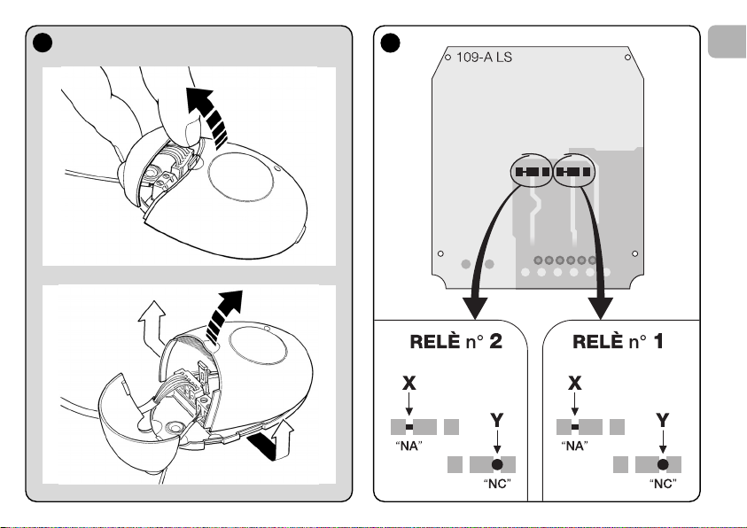
–– How to obtain “
NC” type contacts ––
The outputs are controlled by 2 relays with NO (normally open)
type contact. To change to NC (normally closed) type contact,
proceed as follows:
01. Disconnect the receiver from the power supply.
02. Open the box of the receiver by first raising the smaller
section of the cover (fig. 4-a) and then the larger section
with the key (fig. 4-b).
03. Carefully remove the board and turn it over: the side with
the soldered elements must be facing the user.
04. On the side with the soldered elements, proceed as fol-
lows (fig. 5):
– Cut the traced section at point “X”
– Join the contacts with a drop of tin at points “Y”.
Note – these modifications may be applied to one or
both relays as required.
3
Red
Black
White
White
Purple
Purple
a
Page 9
4
5
EN
a
b
7
Page 10

8
EN
• For all models:
Installation of an external aerial
If the aerial supplied is in an unfavourable position and the
radio signal is weak, an external aerial may be installed to
improve reception (mod. ABF or ABFKIT). The new aerial must
be positioned as high as possible and above any metal or
reinforced concrete structures present in the area.
– Connection to the Control Unit
: Use a coaxial cable with
an impedance of 50 ohm (for example, a RG58 cable with
low loss). Caution! – To reduce signal dispersion use a
cable that is as short as possible (not exceeding 10 m).
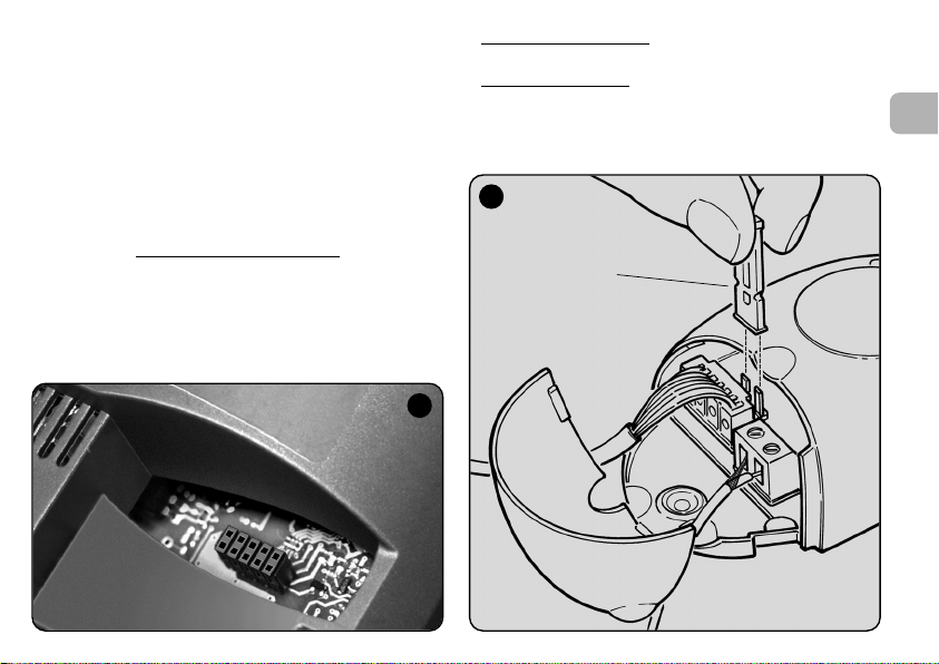
– Connection to the receiver
(only for models with univer-
sal type connection): Open the receiver by first raising the
smaller section of the cover (fig. 4-a) and disconnect the
aerial supplied; then connect the cable of the new aerial to
terminal 1 and 2 as follows (fig. 3-a): Terminal 1 = sheath;
Terminal 2 = core.
6
Programming warnings
The settings described in this chapter (except for procedure 6) require use of the key and led on the receiver (fig.
6). To indicate the state of activity in progress, the led
emits a set number of flashes with a specific duration and
colour (green, red or orange). For the meaning of these
signals, refer to Table A at the end of the manual.
PROGRAMMING THE
MAIN FUNCTIONS
Led Key
Led Key
Page 11

4 – CAUTION! – READ THIS SECTION
BEFORE MEMORISING THE
TRANSMITTER
The receiver can only memorise transmitters belonging to one
of the following 3 encoding families
– family with “O-Code”, “FloR” and “TTS” encoding;
– family with “Flo” encoding;
– family with “Smilo” encoding.
Note – Each code enables use exclusively
associated functions on the receiver.
Caution! – The encoding family
memorised on the receiver also defines the relative
encoding family for the subsequent transmitters to be
memorised.
To change the encoding family
procedure 10 – Total receiver memory deletion.
To check on the receiver whether transmitters and the associated encoding family
lows:
01. Disconnect the receiver from the power supply.
02. Re-connect the power to the receiver and count the
number of green flashes emitted by the receiver led.
03. Check the number of flashes emitted with the data in the
table below:
– 1 flash = Flo encoding
– 2 flashes = O-Code / FloR / TTS encoding
– 3 flashes = Smilo encoding
– 5 flashes = no transmitter entered
are already memorised, proceed as fol-
:
of the standard
of the first transmitter
set on the receiver, perform
Caution! – Before memorising a transmitter, carefully
read all memorisation procedures described below to
select the one most suited to your specific application.
5 – TRANSMITTER MEMORISATION
PROCEDURE: “Mode I” AND “Mode II”
Each control unit has a set number of commands that can be
activated according to the type of receiver: The models with
“SM” connector provide 4 or 15 commands while models
with the universal connection provide 2 outputs.
In general the commands can be associated with the transmitter keys in two ways:
Mode I”. This mode enables memorisation on the receiver
• “
of all transmitter keys
mitters with more than one identity code such as model ON9).
The keys are automatically
mands of the control unit or the receiver outputs, on models
with universal connectotion.
Mode II”. This mode enables memorisation on the receiv-
• “
er of a single transmitter key
which command, among those available on the control unit
(maximum 4) or which output of the receiver to be associated
with the selected key.
– “Extended Mode II”
This mode can only be used with control units using the connection system “T4 Bus”. The “Extended Mode II” is the same
as “Mode II” with the additional option to choose the required
command from those available in the “Table of commands”
(maximum 15), as provided in the manual of the control unit
connected to the receiver.
or a group of the latter at once (on trans-
associated with the pre-set com-
. The user has a free choice of
(only for models with “SM” connector).
EN
9
Page 12

10
EN
5.1 – Memorisation in “MODE I”
Warning – This procedure simultaneously memorises all
keys of the transmitter or a group of the latter (on transmitters with more than one identity code).
01. Press and hold the key on the receiver until the green led
on the receiver illuminates. Then release the key.
02. (within 10 seconds) On the transmitter to be memorised,
press and hold any key until the led on the receiver emits
the first of 3 green flashes to confirm memorisation.
Note – After the three flashes, a 10-second interval is available to memorise another transmitter as required.
5.2 – Memorisation in “MODE II”
(valid also for “Extended Mode II”)
WARNINGS:
– The “Extended Mode II” procedure can only be used
with receivers with “SM” type connectors.
– This procedure enables memorisation of a single trans
-
mitter key.
01. In the control unit manual, look up the “Table of com-
mands”, select the command to assign to the transmitter
key and note the number corresponding to the command.
02. (on the receiver) Press the key the same number of times
as the previously noted number – the Led on the receiv-
er emits the same number of flashes repeated at regular
intervals.
03. (on the transmitter within 10 seconds) Press and hold the
selected key for memorisation until the led on the receiver emits the first of 3 flashes (= memorisation confirmed).
Note – After the three flashes, a 10-second interval is available to memorise the same command on other keys on the
same transmitter or a new transmitter as required.
6 – MEMORISING A TRANSMITTER USING
THE “ENABLE CODE
” OF ANOTHER
TRANSMITTER
[already memorised]
This procedure can only be used if two transmitters with
“O-Code” encoding are used.
The NiceOne transmitters have a secret code
stored in the
memory, known as the “ENABLE CODE”. Thanks to this
code, operation of NEW transmitter can be enabled by simply
transferring the “enable code” of an OLD transmitter (previously memorised on the receiver) onto its memory (fig. 7).
Note – For this procedure, refer to the transmitter manual.
Subsequently, when the NEW transmitter is used, it will transmit its own identity code to the receiver as well as the relative
“enable code” (the first twenty times only). The receiver, after
recognising the “enable code” of an OLD transmitter (previously memorised on the receiver) automatically memorises the
identity code of the NEW transmitter sent to it.
7
Page 13

• Preventing accidental use of this memorisation procedure
To prevent memorisation on the receiver of other transmitters
not compatible with the system but with the “enable code” of
a transmitter already memorised on the receiver, this procedure can be “locked” (or unlocked) by programming the function in paragraph 10.
As an alternative to locking memorisation of the entire receiver,
transfer of the “enable code” can be disabled exclusively for
some or all OLD transmitters already memorised. This operation can be performed using the O-Box programming unit.
7 – MEMORISATION OF A TRANSMITTER
USING THE PROCEDURE IN THE
VICINITY OF THE RECEIVER
[with a transmitter already memorised]
A NEW transmitter can be memorised in the receiver memory
without acting directly on the key of the receiver, but by simply
working within its reception range. To use this procedure, an
OLD transmitter, previously memorised (in “Mode I” or in
“Mode II”) and operative, is required. The procedure enables
the NEW transmitter to receive the settings of the OLD version.
WARNINGS:
• Use only one
according to requirements.
• The procedure must be performed within the reception
range of the receiver (maximum 10-20 m from receiver).
• Repeat the same procedure for each transmitter to be
memorised.
Standard Procedure
01. On the NEW transmitter, press and hold the key…. for at
least 5 seconds (see note 1) and then release.
02. On the OLD transmitter, press key…. three times (see
note 1) and then release.
03. On the NEW transmitter, press the same key pressed in
point 01 once and then release.
Alternative Procedure
01. On the NEW transmitter, press and hold the key…. for at
least 3 seconds (see note 1) and then release.
02. On the OLD transmitter, press and hold the key…. for at
least 3 seconds see note 1) and then release.
of the two procedures described below,
(valid for all Nice receivers)
(valid for this receiver only)
EN
11
Page 14

12
EN
03. On the NEW transmitter, press the same key pressed in
point 01 for at least 3 seconds and then release.
04. On the OLD transmitter, press the same key pressed in
point 02 for at least 3 seconds and then release.
Note 1:
If the OLD transmitter is memorised in “Mode I” the NEW
transmitter will also be memorised in “Mode I”. In this case,
during the procedure press any key
on either the OLD or NEW
transmitter.
If the OLD transmitter is memorised in “Mode II” the NEW
transmitter will also be memorised in “Mode II”. In this case,
during the procedure press the required command key
on the
OLD transmitter and the associated key to be memorised
for
this command on the NEW transmitter. This procedure must
also be repeated for each key of the NEW transmitter to be
memorised.
• Preventing accidental use of this memorisation procedure
To prevent the continuous reception of a signal transmitted at
random by a transmitter not part of the system from accidentally activating the memorisation procedure, this procedure
can be “locked” (or unlocked) by programming the function in
paragraph 10.
8 – TOTAL RECEIVER MEMORY DELETION
All transmitters memorised can be deleted from the receiver
memory, or all data present
in the latter can be deleted as
follows:
01. Press and hold the receiver key and check the following
changes in Led status:
– (after approx. 4 seconds) the green led illuminates;
– (after approx. 4 seconds) the green led turns off;
– (after approx. 4 seconds) the green led starts flashing.
02. At this point release the key
exactly......
• on the 3rd flash, to delete all transmitters
, or,
• on the 5th flash, to delete the entire memory
of the
receiver, including configurations and encoding families of
the transmitters.
Alternatively this function can be performed using the O-Box
or O-View programming unit.
9 – DELETING A SINGLE TRANSMITTER
FROM THE RECEIVER MEMORY
A single transmitter (in your possession) memorised can be
deleted from the receiver memory as follows:
01. Press and hold the receiver key.
02. After approx. 4 seconds the green led illuminates (keep
the key pressed).
03. On the transmitter to be deleted from the memory, press
and hold any key (see note 1) until the led on the receiver
emits 5 green flashes (= deletion confirmed).
Page 15

Note 1:
If the transmitter is memorised in “Mode I” any key can be
pressed.
If the transmitter is memorised in “Mode II” the entire procedure must be repeated for each memorised key to be deleted.
Alternatively this function can be performed using the O-Box
or O-View programming unit.
10 – ENABLING (or disabling)
THE RECEIVER FOR TRANSMITTER
MEMORISATION
This function enables the user to prevent memorisation of new
transmitters when the procedures “in the vicinity”(factory
setting is ON) or with “enable code” (factory setting is ON)
are used as described in this manual. To enable or disable this
function, proceed as follows:
01. Disconnect the receiver from the power supply and wait 5
seconds.
02. Reconnect the power and switch on by pressing the
receiver key until the relative led has completed the signals indicating the type of code stored in the memory
(see paragraph 5) and the procedure is activated, indicated by 2 short orange flashes. Then release the key.
03. (within 5 seconds) Press the receiver key repeatedly to
select one of the following functions (Warning! – on each
press of the key the Led changes colour to indicate the
currently selected function):
• Led OFF = No lock enabled
• Led RED = Memorisation “in the vicinity” locked
• Led GREEN = Memorisation with “enable code” locked
• Led ORANGE = Both memorisation modes locked (“in
the vicinity” and with “enable code”).
04. (within 5 seconds) Press any key of a transmitter already
memorised on the receiver to save the selected function.
Alternatively the lock (or unlock) function can be applied using
the O-Box or O-View programming unit.
EN
13
Page 16
14
EN
11 – MEMORISATION OF A TRANSMITTER
USING THE RECEIVER
“CERTIFICATE NUMBER
”
[with O-Box] – This procedure can only be used if a trans-
mitter is used with “O-Code” encoding and when in possession of the receiver “Certificate Number”.
The “CERTIFICATE” is a personal number (factory set) identi-
fying the single receiver to distinguish it from all others.
Use of this “certificate” simplifies the procedure required to
memorise the transmitter in the receiver, as it no longer obliges the installer to work within the receiver operating range. In
fact the new procedure enables transmitter memorisation
from any distance, even far from the installation site (for example from the installer’s office – fig. 9).
WARNING – The settings described in this chapter
require use of the O-Box or O-View programming unit.
For operation of these devices, refer to the relative
instruction manuals, also available on the internet site:
www.niceforyou.com.
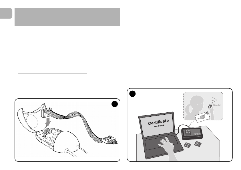
• The models with “SM” connector
are connected to the
O-Box unit by inserting the receiver in the relative connector.
• The models with universal connector
are connected to
the O-Box unit by means of a special cable which must be
connected to the connector on the receiver (see fig. 8).
OTHER FUNCTIONS
8
9
Page 17

Initially, the procedure consists in the installer entering, with
the aid of the programming unit “O-Box”, the required functions and the relative receiver “certificate” in the memory of
the transmitter. The transmitter, ready to use
the client.
Subsequently, when the transmitter is used, it will transmit the
command along with the “certificate” to the receiver (the first
twenty times only). The receiver, after recognising the “certificate” as its own, automatically memorises the identity code of
the transmitter that sent the certificate.
, is then sent to
12 – REMOTE REPLACEMENT OF A
TRANSMITTER USING “PRIORITY”
MODE
[with O-Box] – The identity code of a transmitter in the
NiceOne series is accompanied by a number
which enables the user to specify the transmitter’s priority
level on a receiver with respect to any other transmitters with
the same code.
This “priority” serves to replace, and thus disable, use of a
transmitter that has been lost or stolen, without the need to
return to the client’s system.
Use of priority mode requires knowledge of the code of the
lost transmitter and enables maintenance of the same code
and functions of the previous transmitter.
Therefore the lost transmitter can be disabled by simply
updating the priority level
next highest value.
On first use of the transmitter, the receiver memorises the new
priority level received and ignores any command sent by the
lost or stolen transmitter if subsequently used.
of the new transmitter with the
(from 0 to 3),
This function can be enabled (or disabled) on the receiver (fac-
tory setting ON) and, when active, the receiver does not
update the priority level sent by the transmitter.
13 – ENABLING (or disabling)
RECEPTION OF NON-ORIGINAL
“IDENTITY CODES”
[with O-Box / O-View] – The identity codes of transmitters
with “FloR” and “O-Code” encoding can be modified as
required, using the “O-Box” or “O-View” programming unit.
The receiver can normally recognise whether a code is original
(factory set) or modified.
When this function is enabled or disabled (factory setting ON)
the receiver has the option to accept (or not) the command of
a transmitter with a modified identity code.
14 – LOCKING (or unlocking)
THE MOBILE SECTION (Rolling code)
OF THE IDENTITY CODE
[with O-Box / O-View] – This function enables the user to
lock (or unlock) management on the receiver of the variable
section (rolling code) of an identity code sent by a transmitter.
When the lock function is active (factory setting OFF), the
receiver treats a “rolling code” as if it were a “fixed” code,
ignoring the variable section.
EN
15
Page 18

16
EN
17 – ENABLING (or disabling)
COMMAND DELIVERY ON THE
“T4 BUS” NETWORK
[with O- View] – On systems in which connection is via the
“T4 Bus”, if more than one receiver is installed, and there is the
need for control at a distance greater than that normally covered by the transmitter and receiver, this function can be
enabled (on at least 2 receivers) to increase the receiver
reception range.
This enables the receiver that receives a command “via radio”
to re-transmit the command via the Bus cable
to the final
receiver (in which the sending transmitter identity code is
memorised), so that this can execute the command.
To enable or disable the option to receiver and/or send radio
codes on the “T4 Bus” in a receiver (factory setting OFF), the
receivers concerned must be duly programmed, using the OView programming unit.
18 – CREATING THE “FAMILY GROUPS”
OF TRANSMITTERS
[with O-Box] – Each code memorised on the receiver can
be associated with one or more “family groups”, from the 4
available.
The formation of groups and their activation or deactivation (fac-
tory setting OFF) is managed by means of the O-Box programming unit while use of the groups, for example in a set timeband, is managed by means of the O-View programming unit.
15 – ENABLING (or disabling)
THE “REPEATER” FUNCTION
(Function available only on models OXIT, OXITFM, OX2T,
OX2TFM, in combination with transmitters using O-Code
encoding).
[with O-Box] – If an automation is to be controlled at a distance greater than that normally covered by the transmitter
and receiver, a second receiver may be used (up to a maximum of five) serving to re-transmit, via radio
, the command to
the final receiver (in which the sending transmitter identity
code is memorised), so that this can execute the command.
To enable or disable this function (factory setting OFF) pro-
gramming must be performed both on the additional receivers
and transmitters.
16 – MANAGING RELEASE OF THE
TRANSMITTER KEYS
(Function available only on transmitters using O-Code
encoding)
[with O-Box / O-View] – Normally, after sending a command, on release of the key the manoeuvre is not stopped
immediately but proceeds for a very short pre-set interval.
If necessary, the manoeuvre can be interrupted at the exact
time of key release (required for example during minimal
adjustments) by enabling this function (factory setting OFF).
Page 19

19 – PROTECTION OF PROGRAMMED
FUNCTION SETTINGS
[with O-Box / O-View] – This function enables the user to
protect all programmed functions on the receiver, also disabling functionality of the key and relative led. The function is
enabled by entering a password on the receiver, i.e. a maximum of 10 digits, as set by the installer.
When the function is enabled, before programming and maintenance of the receiver, the special password must be entered
on the programming unit to unlock the receiver.
DISPOSAL OF THE PRODUCT
This product constitutes an integral part of the automation system, therefore it must be disposed of along with it.
As in installation, also at the end of product lifetime, the disassembly and scrapping operations must be performed by qualified personnel.
This product is made up of different types of material, some of
which can be recycled while others must be disposed of. Seek
information on the recycling and disposal systems envisaged
by the local regulations in your area for this product category.
Caution! – some parts of the product may contain pollutant or
hazardous substances which, if disposed of into the environment, may cause serious damage to the environment or physical health.
As indicated by the symbol on the left,
disposal of this product in domestic
waste is strictly prohibited. Separate the
waste into categories for disposal,
according to the methods envisaged by
current legislation in your area, or return
the product to the retailer when purchasing a new version.
Caution! – Local legislation may envisage serious fines in the
event of abusive disposal of this product.
EN
17
Page 20

18
EN
OXI OXIT OXIFM OXITFM
• Decoding “O-Code” / “FloR” / “TTS”; or “Flo”; or “Smilo”
• Maximum absorption 30 mA
• Reception frequency 433.92 MHz 868.46 MHz
• Transmission frequency ––– 433.92 MHz ––– 868.46 MHz
• Sensitivity Above 0.5 µV Above 0.8 µV
• Operating temperature –20° C ÷ +55° C
• Outputs 4 (on “SM” connector)
• Dimensions and weight L. 50; H. 45; P. 19 mm; weight 20
• Radiated power ––– approx. 1 mW E.R.P. ––– approx. 1 mW E.R.P.
• Input impedance 52 ohm
OX2 OX2T OX2FM OX2TFM
• Decoding “O-Code” / “FloR” / “TTS”; or “Flo”; or “Smilo”
•
Power supply
Without electric jumper = 24 V standard. Limits from 18 to 28 V direct or alternating
With electric jumper = 12 V standard. Limits from 10 to 18 V direct or alternating
• Absorption on standby 10 mA at 24 Vac
• Absorption with 2 relays activ 80 mA at 24 Vac.
• Reception frequency 433.92 MHz 868.46 MHz
• Transmission frequency ––– 433.92 MHz ––– 868.46 MHz
• Sensitivity Above 0.5 µV Above 0.8 µV
• N° relays 2
• Relay contact Normally open max 0,5 A and 50 V
• Operating temperature –20° C ÷ +55° C
• Protection rating IP 30
• Dimensions and weight 58 x 86; H. 22 mm; weight 55 g
• Radiated power ––– approx. 1 mW E.R.P. ––– approx. 1 mW E.R.P.
PRODUCT TECHNICAL SPECIFICATIONS
Page 21

GENERAL NOTES
As well as the functions and settings described in this
manual, the receiver offers many other features to
enhance performance, safety and ease of use.
All these settings require use of the O-Box (or in some
cases O-View) programming unit.
For further information on the settings available, refer to
the general system manual “NiceOpera System Book”, or
the O-Box/ O-View programming unit manual.
• Notes on Product Technical specifications
– The range of the transmitters and reception capacity of the
receivers is strongly influenced by other devices (for example: alarms, radio headphones etc.) operating in the zone at
the same frequency. In these cases, Nice cannot guarantee
the effective capacity of its devices.
– All technical specifications stated in this section refer to an
ambient temperature of 20°C (± 5°C).
– Nice reserves the right to apply modifications to the product
at any time when deemed necessary, while maintaining the
same functionalities and intended use.
EN
19
Page 22

20
EN
Table A
SIGNALS EMITTED BY THE
RECEIVER LED
–– Long flashes / GREEN ––
On start-up:
1 ✺ = Code in use: “Flo”
2 ✺ = Code in use: “O-Code”/“FloR”
3 ✺ = Code in use: “Smilo”
5 ✺ = No remote control memorised
During operation:
1 ✺ = Indicates that the code received is not stored in the
memory
1 ✺ = During programming, indicates that the code is
already stored in the memory
3 ✺ = Saving code in memory
5 ✺ = Memory deleted
6 ✺ = During programming, indicates that the code is not
authorised for memorisation
8 ✺ = Memory full
––––––––––––––––––––––––––––––––––––––––––––––––––
–– Short flashes / GREEN ––
1 ✺ = “Certificate” not valid for memorisation
2 ✺ = Code cannot be memorised as is transmitting
“certificate”
3 ✺ = During programming, indicates that the code has
been re-synchronised
4 ✺ = Output in “Mode II” not managed on control unit
5 ✺ = During deletion procedure, indicates that the code
has been deleted
5 ✺ = “Certificate” with higher priority that the admissible
value
6 ✺ = Code synchronisation failure
6 ✺ = Code cannot be memorised due to “incorrect key”
––––––––––––––––––––––––––––––––––––––––––––––––––
–– Long flashes / RED ––
1 ✺ = Non-original code block
2 ✺ = Code with lower priority than the authorised value
––––––––––––––––––––––––––––––––––––––––––––––––––
–– Short flashes / RED ––
1 ✺ = “In vicinity” programming mode block
1 ✺ = Memorisation by means of “certificate” block
2 ✺ = Memory block (PIN entry)
––––––––––––––––––––––––––––––––––––––––––––––––––
–– Long flashes / ORANGE ––
1 ✺ = Indicates that the code is in the memory but
outside the group currently enabled
––––––––––––––––––––––––––––––––––––––––––––––––––
–– Short flashes / ORANGE ––
2 ✺ = Indicates activation of block programming
(on start-up)
Page 23

EC DECLARATION OF CONFORMITY
Note –This Declaration of Conformity contains the individual declarations of conformity for the specified products; it was updated on the issue
date of this manual and the text herein has been drawn up for editorial purposes. A copy of the original declaration for each product can be
requested from Nice S.p.a. (TV) I.
Number: 256/OXI Revision: 3 Language: EN
The undersigned Luigi Paro, as Managing Director, declares on his own responsibility that the product:
Manufacturer’s name : Nice S.p.a.
Address: Via Pezza Alta 13, Z.I. Rustignè, 31046 Oderzo (TV) Italy
Type: Receiver and receiver-transmitter for remote control of automations for doors, gates, shutters,
Models: OXI, OXIT, OXIFM, OXITFM
Accessories:
conform with the requirements of the EC directive:
• 1999/5/EC; DIRECTIVE 1999/5/EC OF THE EUROPEAN PARLIAMENT AND COUNCIL of 9 March 1999 regarding
radio equipment and telecommunications terminal equipment and the mutual recognition of their conformity
According to the following harmonised standards
Health protection (art.3(1)(a)): EN 50371:2002
Electrical safety (art.3(1)(a)): EN 60950-1:2006; +A11:2009
Electromagnetic compatibility (art.3(1)(b)): EN 301 489-1V1.6.1:2006; EN 301 489-3V1.4.1:2002
Radio range (art.3(2)): EN 300220-2V2.3.1:2010
Oderzo, 12 August 2011 Luigi Paro (Managing Director)
awnings, rolling shutters and similar applications.
EN
21
Page 24

22
EN
EC DECLARATION OF CONFORMITY
Note –This Declaration of Conformity contains the individual declarations of conformity for the specified products; it was updated on the issue
date of this manual and the text herein has been drawn up for editorial purposes. A copy of the original declaration for each product can be
requested from Nice S.p.a. (TV) I.
Number: 259/OX2 Revision: 5 Language: EN
The undersigned Luigi Paro, as Managing Director, declares on his own responsibility that the product:
Manufacturer’s name : Nice S.p.a.
Address: Via Pezza Alta 13, Z.I. Rustignè, 31046 Oderzo (TV) Italy
Type: Receiver and receiver-transmitter for remote control of automations for doors, gates, shutters,
awnings, rolling shutters and similar applications.
Models: OX2, OX2T, OX2FM, OX2TFM
Accessories:
conform with the requirements of the EC directive:
• 1999/5/EC; DIRECTIVE 1999/5/EC OF THE EUROPEAN PARLIAMENT AND COUNCIL of 9 March 1999 regarding
radio equipment and telecommunications terminal equipment and the mutual recognition of their conformity
According to the following harmonised standards
Health protection (art.3(1)(a)): EN 50371:2002
Electrical safety (art.3(1)(a)): EN 60950-1:2006; +A11:2009
Electromagnetic compatibility (art.3(1)(b)): EN 301 489-1V1.6.1:2006; EN 301 489-3V1.4.1:2002
Radio range (art.3(2)): EN 300220-2V2.3.1:2010
Oderzo, 12 August 2011 Luigi Paro (Managing Director)
Page 25

ITALIANO
Istruzioni originali
1 – DESCRIZIONE DEL PRODOTTO E
DESTINAZIONE D’USO
Il presente ricevitore fa parte della serie “NiceOne” di Nice spa.
I ricevitori di questa serie sono destinati all’uso sulle Centrali di
comando presenti negli impianti di automatizzazione di cancelli, portoni da garage e alzabarriere stradali. Ogni altro uso è
da considerarsi improprio e vietato! Il costruttore non
risponde dei danni risultanti da un uso improprio del prodotto, diverso da quanto previsto nel presente manuale.
Sono disponibili vari modelli, con le caratteristiche essenziali
riportate nella tabella in basso.
1.1 – Il sistema “NiceOpera”
I ricevitori della serie NiceOne fanno parte del sistema
“NiceOpera”. Questo sistema è stato progettato da Nice per
semplificare le fasi di programmazione, di uso e di manutenzione dei dispositivi usati negli impianti di automatizzazione.
Il sistema è formato da vari dispositivi, software e hardware,
capaci di scambiarsi fra loro dati e informazioni via radio, attraverso un sistema di codifica chiamato “O-Code” o un collegamento ‘fisico’, tramite cavo.
I principali dispositivi che formano il sistema NiceOpera sono:
– trasmettitori NiceOne;
– ricevitori NiceOne;
– unità di programmazione O-Box;
– centrali e motoriduttori con “Bus T4”;
– programmatore O-View per dispositivi con “Bus T4”.
IMPORTANTE – Per approfondire in dettaglio tutte le funzionalità del sistema NiceOpera e l’interdipendenza operativa che lega i vari dispositivi del sistema, consultare il
manuale generale “NiceOpera System Book”, disponibile
anche nel sito internet www.niceforyou.com
IT
Mod. Frequenza Funzione Connessione
OXI 433.92 MHz Ricevitore ad innesto
OXIFM 868.46 MHz Ricevitore ad innesto
OXIT 433.92 MHz Ricetrasmettitore ad innesto
OXITFM 868.46 MHz Ricetrasmettitore ad innesto
OX2 433.92 MHz Ricevitore con cavo a 6 fili
OX2FM 868.46 MHz Ricevitore con cavo a 6 fili
OX2T 433.92 MHz Ricetrasmettitore con cavo a 6 fili
OX2TFM 868.46 MHz Ricetrasmettitore con cavo a 6 fili
Note alla tabella:
– Le frequenze 433.92 MHz
e 868.46 MHz non sono
compatibili tra loro.
– La lettera “T” nella sigla indica un ricevitore con un trasmettitore incorporato.
1
Page 26

2
IT
2 – CARATTERISTICHE FUNZIONALI DEL
PRODOTTO
• Per tutti i modelli
– Il ricevitore gestisce la codifica radio chiamata “O-Code”,
con codice variabile (rolling-code), che permette di sfruttare
tutte le nuove funzioni del Sistema NiceOpera.
Il ricevitore è compatibile anche con le codifiche “FloR”,
“TTS”, “Smilo” e “Flo”. In questo caso però, non sarà pos-
sibile sfruttare alcune funzionalità esclusive del Sistema
NiceOpera, descritte in questo manuale.
– Il ricevitore dispone di una memoria con 1024 spazi in cui
memorizzare i trasmettitori. Se questo viene memorizzato in
“Modo I”, tutti i suoi tasti
occuperanno 1 spazio di memoria;
se invece viene memorizzato in “Modo II”, ogni suo tasto
memorizzato occuperà 1 spazio di memoria (per le modalità
di memorizzazione, vedere avanti nel manuale).
– Ogni ricevitore possiede un proprio numero di identificazio
-
ne chiamato “Certificato”. Questo numero permette di
accedere a molte operazioni come, ad esempio: la memorizzazione di nuovi trasmettitori senza la necessità di intervenire direttamente sul ricevitore e l’uso dell’unità O-View
sfruttando il collegamento con “Bus T4”.
Il tagliando sigillato contenuto nella confezione del prodotto
riporta stampato al suo interno il numero di certificato
appartenente al presente ricevitore. Attenzione! – questo
tagliando deve essere custodito in un posto sicuro perché
consente l’accesso ai dati contenuti nel ricevitore, a meno
che, non vengano inserite ulteriori protezioni come l’uso di
Password di sicurezza.
• Per i modelli con innesto “SM”
– Questi modelli possono essere usati esclusivamente con le
Centrali di comando dotate di connettore ad innesto di tipo
“SM” (fig. 1). Nota - per identificare le Centrali idonee, con-
sultare il catalogo prodotti di Nice.
– Questi modelli riconoscono automaticamente le caratteristi-
che della Centrale nella quale vengono inseriti e il ricevitore
si auto-imposta nel modo seguente.
• Se la Centrale gestisce il “Bus T4”
, il ricevitore rende
disponibili fino a 15 comandi diversi.
• Se la Centrale non gestisce il “Bus T4”
, il ricevitore ren-
de disponibili fino a 4 canali comandi diversi.
Attenzione! – In ambedue i casi, il numero e la varietà dei
comandi a disposizione dipendono dal tipo e dal modello di
Centrale che si utilizza. La “Tabella dei comandi” di ciascuna
Centrale è riportata nel manuale istruzioni della Centrale
stessa.
• Per i modelli con connessione universale
– Questi modelli funzionano con 2 relè a contatto pulito; quin-
di possono essere usati con qualsiasi tipo di Centrale.
• Per i modelli con la “T” nella sigla
– Questi modelli sono dotati della funzione “Repeater” (vedere
avanti nel manuale) che consente di aumentare il raggio di
trasmissione dei trasmettitori. Inoltre, consentono di poter
comunicare in modo “wireless” con l’unità di programmazione O-Box.
Page 27
3 – INSTALLAZIONE DEL PRODOTTO
• Per i modelli con innesto “SM”
Questi modelli si collegano alla Centrale di comando innestando il loro connettore in quello specifico presente sulla Centrale
(fig. 1). Attenzione! – Prima di innestare o di rimuovere il
ricevitore, togliere l’alimentazione elettrica alla Centrale.
Inoltre, occorre installare anche l’antenna in dotazione, collegandola agli appositi morsetti presenti sulla Centrale.
• Per i modelli con connessione universale
––– Selezione dell’alimentazione –––
Questi modelli si collegano alla Centrale di comando tramite
un cavo con 6 fili interni. Prima di collegare il cavo, selezionare
il tipo di alimentazione desiderata, lasciando inserito o togliendo il ponticello elettrico (fig. 2-a) nel modo seguente:
1
– Ponticello NON inserito
(limiti di tensione: 18 ÷ 28 V)
– Ponticello INSERITO
(limiti di tensione: 10 ÷ 18 V)
2
a
= 24 V ac/dc
= 12 V ac/dc
IT
3
Page 28

4
IT
––– Collegamenti elettrici –––
Collegare negli appositi morsetti presenti sulla Centrale i 6 fili
elettrici del cavo del ricevitore nel modo seguente (fig. 3):
• Rosso e Nero = ALIMENTAZIONE
(rosso = Positivo, nero = Negativo. In corrente alternata,
questo è indifferente).
• Bianco e Bianco = USCITA 1° RELÈ
(contatto pulito di un relè normalmente aperto).
• Viola e Viola = USCITA 2° RELÈ
(contatto pulito di un relè normalmente aperto).
––– Come ottenere contatti di tipo “
NC” –––
Le uscite sono comandate da 2 relè con contatto di tipo “NA”
(normalmente aperto). Se si vuole ottenere un contatto di tipo
“NC” (normalmente chiuso), procedere nel modo seguente:
01. Togliere l’alimentazione elettrica al ricevitore.
02. Aprire il box del ricevitore sollevando prima la parte pic-
cola del coperchio (fig. 4-a) e successivamente quella
grande con il tasto (fig. 4-b).
03. Estrarre con cura la scheda e girarla: il lato con le salda-
ture deve essere rivolto verso l’osservatore.
04. Sul lato con le saldature, effettuare le seguenti operazioni
(fig. 5):
– Tagliare il tratto di traccia nel punto “X”.
– Unire con una goccia di stagno le piazzole nei punti “Y”.
Nota – queste modifiche possono essere fatte su un relè
o sutti e due, secondo le vostre necessità.
3
Rosso
Nero
Bianco
Bianco
Viola
Viola
a
Page 29

4
5
IT
a
b
5
Page 30

6
IT
• Per tutti i modelli:
installazione di un’antenna esterna
Se l’antenna in dotazione viene a trovarsi in posizione sfavorevole e il segnale radio risulta debole, per migliorare la ricezione
è consigliabile sostituire questa installando un’antenna esterna (mod. ABF o ABFKIT). La nuova antenna deve essere posizionata più in alto possibile e al di sopra di eventuali strutture
metalliche o di cemento armato presenti nella zona.
– Collegamento alla Centrale
: usare un cavo coassiale con
impedenza di 50 ohm (ad esempio, il cavo RG58 a bassa
perdita). Attenzione! – Per ridurre la dispersione del segnale,
usare un cavo più corto possibile (non deve superare i 10 m).
– Collegamento al ricevitore
(solo per i modelli con con-
nessione universale): aprire il ricevitore sollevando la parte
piccola del coperchio (fig. 4-a) e scollegare l’antenna in
dotazione; quindi, collegare il cavo della nuova antenna al
morsetto 1 e 2 in questo modo (fig. 3-a): morsetto 1 = cal-
za; morsetto 2 = anima.
Avvertenze alla programmazione
Le programmazioni presenti in questo capitolo (esclusa la
procedura 6) richiedono l’uso del tasto e del Led sul ricevitore (fig. 6). Per indicare lo stato delle attività in corso, il
Led emette un determinato numero di lampeggi con una
durata specifica e un determinato colore di luce (verde,
rosso o arancione). Per conoscere il significato di queste
segnalazioni consultare la Tabella A, presente alla fine
del manuale.
PROGRAMMAZIONE DELLE
FUNZIONI PRINCIPALI
6
Led Tasto
Led Tasto
Page 31

4 – ATTENZIONE! – LEGGERE QUI
PRIMA DI MEMORIZZARE UN
TRASMETTITORE
Il ricevitore può memorizzare solo i trasmettitori appartenenti
ad una delle seguenti 3 famiglie di codifica
– famiglia formata dalle codifiche “O-Code”, “FloR” e “TTS”;
– famiglia formata dalla codifica “Flo”;
– famiglia formata dalla codifica “Smilo”.
Nota – Ogni singola codifica permette di sfruttare nel ricevito-
le funzionalità tipiche di quella determinata codifica.
re solo
Attenzione! – La famiglia di codifica
ne il primo
nisce anche la famiglia alla quale dovranno appartenere i
successivi trasmettitori da memorizzare.
Per cambiare la famiglia di codifica
necessario eseguire la procedura 10 – Cancellazione totale
della memoria del ricevitore.
Per sapere se nel ricevitore sono già memorizzati dei trasmettitori e la famiglia di codifica
cedere nel modo seguente:
01. Togliere l’alimentazione elettrica al ricevitore.
02. Ridare l’alimentazione al ricevitore e contare il numero dei
03. Infine, confrontare il numero dei lampeggi emessi con la
trasmettitore memorizzato nel ricevitore defi-
alla quale essi appartengono, pro-
lampeggi di colore verde che emette il Led sul ricevitore.
seguente tabella:
– 1 lampeggio = codifica Flo
– 2 lampeggi = codifica O-Code / FloR / TTS
– 3 lampeggi = codifica Smilo
– 5 lampeggi = nessun trasmettitore inserito
:
alla quale appartie-
presente nel ricevitore, è
Attenzione! – Prima di iniziare la memorizzazione di un
trasmettitore, leggere attentamente tutte le modalità di
memorizzazione descritte di seguito per valutare quale di
queste risulta più adeguata al vostro caso specifico.
5 – MODALITÀ DI MEMORIZZAZIONE DI
UN TRASMETTITORE: “Modo I” E
“Modo II”
Ogni Centrale dispone di un determinato numero di comandi
che possono essere attivati in base al tipo di ricevitore: i
modelli con innesto “SM” rendono disponibili 4 o 15 coman-
di; i modelli con connessione universale rendono disponibi-
li 2 uscite.
In generale, l’abbinamento tra questi comandi e i tasti di un
trasmettitore può essere fatto in due modalità diverse:
• “
Modo I”. Questa modalità permette di memorizzare nel
ricevitore, in una sola volta, tutti i tasti del trasmettitore
solo gruppo di essi (nei trasmettitori che hanno più codici di
identità come ad esempio il modello ON9). I tasti vengono
abbinati automaticamente
le o alle uscite del ricevitore, nei modelli con connessione universale.
• “
Modo II”. Questa modalità permette di memorizzare nel
ricevitore un singolo tasto del trasmettitore
gliere liberamente
Centrale (massimo 4) o a quale uscita del ricevitore, abbinare il
tasto prescelto.
– “Modo II esteso”
Questa modalità può essere usata unicamente con le Centrali che utilizzano il sistema di collegamento “Bus T4”. Il “Modo II
esteso” è uguale al “Modo II” ma offre in più la possibilità di
ai comandi prestabiliti nella Centra-
. L’utente può sce-
a quale comando, tra quelli disponibili nella
(solo per i modelli con innesto “SM”).
o un
IT
7
Page 32

8
IT
scegliere il comando desiderato fra quelli disponibili nella
“Tabella dei comandi” (massimo 15), presente nel manuale
della Centrale in cui è innestato il ricevitore.
5.1 – Memorizzazione in “MODO I”
Avvertenza – L’esecuzione di questa procedura memorizza contemporaneamente tutti i tasti
del trasmettitore o
un solo gruppo di essi (nei trasmettitori che hanno più
codici di identità).
01. Mantenere premuto il tasto sul ricevitore fino a quando si
accende il Led verde sul ricevitore. Quindi, rilasciare il
tasto.
02. (entro 10 secondi) Sul trasmettitore da memorizzare,
mantenere premuto un tasto qualsiasi fino a quando il
Led sul ricevitore emette il primo dei 3 lampeggi di colore
verde che segnalano l’avvenuta memorizzazione.
Nota – Dopo i tre lampeggi, sono disponibili altri 10 secondi
per memorizzare ulteriori trasmettitori.
5.2 – Memorizzazione in “MODO II”
(valida anche per il “MODO II esteso”)
Avvertenze:
– La procedura “Modo II esteso” può essere usata solo
con i ricevitori con innesto “SM”.
– L’esecuzione di questa procedura memorizza un singo
-
lo tasto del trasmettitore.
01. Cercare nel manuale della Centrale la “Tabella dei coman-
di” disponibili; scegliere il comando che si desidera asse-
gnare al tasto del trasmettitore e infine, annotare il numero che corrisponde al comando.
02. (sul ricevitore) Premere il tasto un numero di volte uguale
al numero annotato prima – il Led del ricevitore emette
uno stesso numero di lampeggi ripetuti.
03. (sul trasmettitore, entro 10 secondi) Mantenere premuto il
tasto prescelto per la memorizzazione, fino a quando il
Led del ricevitore emette il primo dei 3 lampeggi (=
memorizzazione avvenuta).
Nota – Dopo i tre lampeggi, sono disponibili altri 10 secondi
per memorizzare lo stesso comando su altri tasti dello stesso
trasmettitore o di un nuovo trasmettitore.
6 – MEMORIZZAZIONE DI UN TRASMET-
TITORE USANDO IL “CODICE DI ABI
LITAZIONE” DI UN ALTRO TRASMETTITORE
[già memorizzato]
Questa procedura può essere usata solo se si utilizzano due
trasmettitori con codifica “O-Code”.
I trasmettitori NiceOne hanno un codice segreto
inserito in
memoria, chiamato “CODICE DI ABILITAZIONE”. Grazie a
questo codice è possibile abilitare il funzionamento di un
NUOVO trasmettitore, semplicemente trasferendo nella sua
memoria il “codice di abilitazione” di un VECCHIO trasmettitore, già memorizzato nel ricevitore (fig. 7). Nota – Per effettua-
re questa procedura, consultare il manuale del trasmettitore.
In seguito, quando il NUOVO trasmettitore verrà usato, trasmetterà al ricevitore oltre al proprio codice di identità, anche il
“codice di abilitazione” (solo per le prime 20 volte). Il ricevitore,
dopo aver riconosciuto il “codice di abilitazione” di un VECCHIO trasmettitore già presente nella sua memoria, memorizzerà automaticamente il codice d’identità di questo NUOVO
trasmettitore che glielo ha inviato.
Page 33

• Impedire l’uso accidentale di questa procedura di
memorizzazione
Per impedire che nel ricevitore possano essere memorizzati
trasmettitori estranei all’impianto, ma in possesso del “codice
di abilitazione” di un trasmettitore già memorizzato nel ricevitore, si può “bloccare” (o sbloccare) questa procedura programmando la funzione del paragrafo 10.
In alternativa al blocco della memorizzazione dell’intero ricevitore è possibile disattivare il trasferimento del “codice di abilitazione” solo di alcuni o di tutti i VECCHI trasmettitori già
memorizzati. Questa operazione può essere fatta con la unità
di programmazione O-Box.
7
7 – MEMORIZZAZIONE DI UN TRASMET-
TITORE USANDO LA PROCEDURA
‘IN VICINANZA DEL RICEVITORE
[con un trasmettitore già memorizzato]
È possibile memorizzare un NUOVO trasmettitore nella
memoria del ricevitore senza agire direttamente sul tasto di
questo ricevitore, ma operando semplicemente nel suo raggio
di ricezione. Per attuare la procedura è necessario avere a
disposizione un VECCHIO trasmettitore, già memorizzato (in
“Modo I” o in “Modo II”) e funzionante. La procedura consentirà al NUOVO trasmettitore di ricevere le impostazioni di quello VECCHIO.
Avvertenze:
• Usare solo una
secondo le proprie necessità.
• La procedura deve essere eseguita operando nel raggio
di ricezione del ricevitore (10-20 m dal ricevitore).
• Ripetere tutta la procedura per ogni trasmettitore che si
desidera memorizzare.
Procedura standard
01. Sul NUOVO trasmettitore, mantenere premuto per alme-
no 5 secondi il tasto.... (vedere nota 1) e poi rilasciarlo.
02. Sul VECCHIO trasmettitore, premere 3 volte il tasto....
(vedere nota 1) e poi rilasciarlo.
03. Sul NUOVO trasmettitore, premere 1 volta lo stesso tasto
del punto 01 e poi rilasciarlo.
Procedura alternativa
01. Sul NUOVO trasmettitore, mantenere premuto per alme-
delle due procedure che seguono,
(valida per tutti i ricevitori di Nice)
(valida solo per questo ricevitore)
’
IT
9
Page 34

10
IT
no 3 secondi il tasto.... (vedere nota 1) e poi rilasciarlo.
02. Sul VECCHIO trasmettitore, mantenere premuto per
almeno 3 secondi il tasto.... (vedere nota 1) e poi rila-
sciarlo.
03. Sul NUOVO trasmettitore, mantenere premuto per almeno
3 secondi lo stesso tasto del punto 01 e poi rilasciarlo.
04. Sul VECCHIO trasmettitore, mantenere premuto per
almeno 3 secondi lo stesso tasto del punto 02 e poi rilasciarlo.
Nota 1:
Se il VECCHIO trasmettitore è memorizzato in “Modo I” anche
il NUOVO trasmettitore verrà memorizzato in “Modo I”. In questo caso, durante la procedura può essere premuto un tasto
qualsiasi sia sul VECCHIO che sul NUOVO trasmettitore.
Se invece il VECCHIO trasmettitore è memorizzato in “Modo II”
anche il NUOVO trasmettitore verrà memorizzato in “Modo II”. In
questo caso, durante la procedura si dovrà premere sul VECCHIO trasmettitore il tasto del comando desiderato
e nel NUO-
VO trasmettitore il tasto che si desidera memorizzare
per quel
comando. Inoltre, la procedura deve essere ripetuta per ogni
tasto del NUOVO trasmettitore che si desidera memorizzare.
• Impedire l’uso accidentale di questa procedura di
memorizzazione
Per impedire che la ricezione continua di un segnale trasmesso casualmente da un trasmettitore estraneo all’impianto,
possa attivare accidentalmente la procedura di memorizzazione, si può “bloccare” (o sbloccare) quest’ultima programmando la funzione del paragrafo 10.
8 – CANCELLAZIONE TOTALE DELLA
MEMORIA DEL RICEVITORE
Per cancellare nella memoria del ricevitore tutti i trasmettitori
memorizzati o, in alternativa, tutti i dati presenti, procedere nel
modo seguente:
01. Mantenere premuto a lungo il tasto del ricevitore e osservare i seguenti cambiamenti di stato del Led:
– (dopo circa 4 secondi) si accende il Led verde;
– (dopo circa 4 secondi) si spegne il Led verde;
– (dopo circa 4 secondi) il Led verde inizia a lampeggiare.
02. A questo punto, rilasciare il tasto
esattamente......
• durante il 3° lampeggio, per cancellare tutti i trasmet
-
titori; oppure,
• durante il 5° lampeggio, per cancellare tutta la memo
ria del ricevitore, comprese le configurazioni e la famiglia
di codifica dei trasmettitori.
In alternativa, questa funzione può essere eseguita anche con
l’unità di programmazione O-Box o O-View.
9 – CANCELLAZIONE DI UN SINGOLO
TRASMETTITORE DALLA MEMORIA
DEL RICEVITORE
Per cancellare nella memoria del ricevitore un singolo trasmettitore memorizzato e in vostro possesso, procedere nel modo
seguente:
01. Mantenere premuto a lungo il tasto del ricevitore.
02. Dopo circa 4 secondi si accende il Led con luce verde
(continuare a tenere premuto il tasto).
03. Sul trasmettitore che si vuole cancellare dalla memoria,
Page 35

mantenere premuto un tasto (vedere nota 1) fino a quando il Led del ricevitore emette 5 lampeggi veloci di color
verde (= cancellazione avvenuta).
Nota 1:
Se il trasmettitore è memorizzato in “Modo I” si può premere
un tasto qualsiasi.
Se il trasmettitore è memorizzato in “Modo II” l’intera procedura deve essere ripetuta per ciascun tasto memorizzato che
si desidera cancellare.
In alternativa, questa funzione può essere eseguita anche con
l’unità di programmazione O-Box o O-View.
10 – ABILITAZIONE (o disabilitazione)
DEL RICEVITORE ALLA MEMORIZZAZIONE DEI TRASMETTITORI
Questa funzione permette di impedire la memorizzazione di
nuovi trasmettitori quando vengono utilizzate le procedure “in
vicinanza” (l’impostazione di fabbrica è ON) o con “codice di
abilitazione” (l’impostazione di fabbrica è ON) descritte in
questo manuale. Per attivare o disattivare questa funzione
funzione, procedere nel modo seguente:
01. Togliere l’alimentazione elettrica al ricevitore e attendere 5
secondi.
02. Dare di nuovo alimentazione tenendo premuto il tasto del
ricevitore fino a quando terminano le segnalazioni del suo
Led relative al tipo di codice in memoria (vedere paragrafo 5) e si attiva la procedura segnalata da 2 lampeggi brevi di colore arancione. Quindi, rilasciare il tasto.
03. (entro 5 secondi) Premere ripetutamente il tasto del ricevitore per scegliere una delle seguenti funzioni (Attenzio-
ne! – ad ogni pressione del tasto il Led cambia colore
indicando la funzione selezionata in quell’istante):
• Led SPENTO = Nessun blocco attivo
• Led ROSSO = Blocco della memorizzazione “in vici-
nanza”
• Led VERDE = Blocco della memorizzazione con “codi-
ce di abilitazione”
• Led ARANCIONE = Blocco di entrambe le memorizza-
zioni (“in vicinanza” e con “codice di abilitazione”)
04. (entro 5 secondi) Premere su un trasmettitore già memorizzato nel ricevitore, un tasto qualsiasi per salvare la funzione appena scelta.
In alternativa, il blocco (o lo sblocco) può essere effettuato
anche con l’unità di programmazione O-Box o O-View.
IT
11
Page 36

12
IT
11 – MEMORIZZAZIONE DI UN TRASMET-
TITORE USANDO IL “NUMERO DI
CERTIFICATO” DEL RICEVITORE
[con O-Box] – Questa procedura può essere usata solo se si
utilizza un trasmettitore con codifica “O-Code” e se si possiede il “Numero di Certificato” del ricevitore.
Il “CERTIFICATO” è un numero personale (programmato in fab-
brica) che identifica il singolo ricevitore e lo distingue dagli altri.
L’uso del “certificato” semplifica la procedura di memorizzazione del trasmettitore nel ricevitore, in quanto non obbliga più
l’installatore ad operare nel raggio di ricezione del ricevitore.
Questa prassi permette infatti di predisporre il trasmettitore
alla memorizzazione, operando anche lontano dal luogo dell’installazione (ad esempio, nell’ufficio dell’installatore - fig. 9).
AVVERTENZA – Le programmazioni descritte in questo
capitolo richiedono l’uso delle unità di programmazione
O-Box o O-View. Per il funzionamento di questi dispositivi, vedere i loro manuali di istruzione, disponibili anche
nel sito internet: www.niceforyou.com.
• I modelli con innesto “SM”
si collegano all’unità O-Box
inserendo il ricevitore nell’apposito connettore.
• I modelli con connessione universale
si collegano
all’unità O-Box tramite un apposito cavo che deve essere
collegato al connettore presente nel ricevitore (vedere
fig. 8).
ALTRE FUNZIONI
8
9
Page 37

Inizialmente, la procedura prevede che l’installatore inserisca
con l’O-Box, nella memoria del trasmettitore, le funzioni desiderate e il “certificato” del ricevitore in cui il trasmettitore dovrà
essere memorizzato. Poi, successivamente farà recapitare al
cliente il trasmettitore già pronto per all’uso
In seguito, quando il trasmettitore verrà usato, trasmetterà al
ricevitore oltre al comando, anche il “certificato” (solo per le
prime 20 volte). Il ricevitore, dopo aver riconosciuto come proprio il “certificato”, memorizzerà automaticamente il codice
d’identità del trasmettitore che glielo ha inviato.
.
12 – SOSTITUZIONE A DISTANZA DI UN
TRASMETTITORE MEMORIZZATO
UTILIZZANDO LA “PRIORITÀ”
[con O-Box] – Il codice di identità di un trasmettitore della
serie NiceOne è accompagnato da un numero
permette di stabilire nel ricevitore il suo livello di priorità
rispetto ad eventuali altri trasmettitori con lo stesso codice.
La “priorità” ha lo scopo di sostituire e quindi di disabilitare
l’uso di un trasmettitore che è stato smarrito o rubato, senza
la necessità di recarsi presso l’impianto del cliente.
L’uso della priorità richiede la conoscenza del codice del trasmettitore smarrito e consente di mantenere lo stesso codice
e le stesse funzioni del trasmettitore precedente.
Quindi, il trasmettitore smarrito può essere disattivato semplicemente aggiornando il
tore al valore successivo più alto.
Al primo uso del trasmettitore, il ricevitore memorizzerà il nuo-
vo livello di priorità ricevuto e ignorerà qualsiasi comando
inviato dal trasmettitore smarrito o rubato, qualora questo
dovesse essere usato.
livello di priorità del nuovo trasmetti-
(da 0 a 3), che
È possibile abilitare (o disabilitare) questa funzione nel ricevitore
(l’impostazione di fabbrica è ON) e, quando questa è attiva, il
ricevitore non aggiorna il livello di priorità inviato dal trasmettitore.
13 – ABILITAZIONE (o disabilitazione)
DELLA RICEZIONE DEI “CODICI DI
IDENTITÀ” NON ORIGINALI
[con O-Box / O-View] – I codici d’identità dei trasmettitori
con codifica “FloR” e “O-Code” possono essere modificati
secondo le proprie esigenze, usando l’unità di programmazione “O-Box” o “O-View”. Normalmente, il ricevitore riesce a
riconoscere se un codice è originale (programmato in fabbrica) o modificato.
Abilitando o disabilitando questa funzione (l’impostazione di
fabbrica è ON) il ricevitore avrà la possibilità o meno di accet-
tare il comando di un trasmettitore con il codice d’identità
modificato.
14 – BLOCCO (o sblocco) DELLA PARTE
MOBILE (Rolling code) DEL CODICE
D’IDENTITÀ
[con O-Box / O-View] – Questa funzione permette di bloc-
care (o sbloccare) nel ricevitore la gestione della parte variabile (rolling code) di un codice d’identità inviato da un trasmetti-
tore. Quando la funzione di blocco è attiva (l’impostazione di
fabbrica è OFF), il ricevitore tratta un codice di tipo “rolling
code” come se fosse un codice di tipo “fisso”, ignorandone la
parte variabile.
IT
13
Page 38

14
IT
vitore questa funzione (l’impostazione di fabbrica è OFF).
17 – ATTIVAZIONE (o disattivazione)
DELL’INVIO DEI COMANDI SULLA
RETE “BUS T4”
[con O-View] – Negli impianti in cui il collegamento è effet-
tuato con “Bus T4”, se sono installati più di un ricevitore e c’è
la necessità di comandare l’automazione da una distanza
superiore a quella normalmente coperta dal trasmettitore e dal
ricevitore, è possibile attivare questa funzione (almeno in 2
ricevitori) per aumentare il raggio di ricezione del ricevitore.
Ciò permette al ricevitore che ha ricevuto un comando “via
radio”, di ritrasmettere a sua volta, attraverso il cavo Bus
, il
comando verso il ricevitore destinatario (in cui è memorizzato il
codice di identità del trasmettitore da cui è partito il comando),
in modo che quest’ultimo possa eseguire il comando.
Per abilitare o disabilitare la possibilità di ricevere e/o inviare i
codici radio sul “Bus T4” in un ricevitore (l’impostazione di fab-
brica è OFF), occorre programmare opportunamente i ricevitori interessati, usando l’unità di programmazione O-View.
18 – CREAZIONE DEL “GRUPPO DI AP -
PARTENENZA” DEI TRASMETTITORI
[con O-Box] – Ogni codice memorizzato nel ricevitore può
essere associato ad uno o più “gruppi di appartenenza”, tra i 4
disponibili.
La formazione dei gruppi e la loro attivazione o disattivazione
(l’impostazione di fabbrica è OFF) è gestita tramite l’unità di
15 – ATTIVAZIONE (o disattivazione)
DELLA FUNZIONE “REPEATER”
(Funzione disponibile solo nei modelli OXIT, OXITFM,
OX2T, OX2TFM, abbinati ai trasmettitori con codifica OCode)
[con O-Box] – Se c’è la necessità di comandare un’automazione da una distanza superiore a quella normalmente coperta dal trasmettitore e dal ricevitore, è possibile utilizzare un
secondo ricevitore (fino a un massimo di 5) con il compito di
ritrasmettere a sua volta, via radio
, il comando verso il ricevitore destinatario (in cui è memorizzato il codice di identità del
trasmettitore da cui è partito il comando), in modo che quest’ultimo possa eseguire il comando.
Per attivare o disattivare questa funzione (l’impostazione di
fabbrica è OFF) occorre effettuare la programmazione sia ne
i
ricevitori aggiunti, sia nei trasmettitori.
16 – GESTIONE DEL RILASCIO DEI TASTI
DEL TRASMETTITORE
(Funzione disponibile solo con i trasmettitori con codifica
O-Code)
[con O-Box / O-View] – Normalmente, dopo aver inviato un
comando, al rilascio del tasto la manovra non si ferma in quel
preciso istante ma prosegue ancora per un tempo brevissimo
prefissato.
Se c’è la necessità che la manovra si interrompa esattamente
nell’istante in cui si rilascia il tasto del comando (ad esempio,
durante le regolazioni minimali), è necessario attivare nel rice-
Page 39

programmazione O-Box, mentre l’utilizzo dei gruppi, ad
esempio in una determinata fascia oraria, è gestito dall’unità di
programmazione O-View.
19 – PROTEZIONE DELLA CONFIGURA-
ZIONE DELLE FUNZIONI PROGRAMMATE
[con O-Box / O-View] – Questa funzione permette di pro-
teggere tutte le funzioni programmate nel ricevitore, disabilitando inoltre, la funzionalità del tasto e del Led. La funzione si
attiva inserendo nel ricevitore una password, cioè un numero
di massimo 10 cifre, stabilito dall’installatore.
Quando la funzione è attiva, per poter effettuare la programmazione e la manutenzione del ricevitore occorre inserire
all’inizio, nell’unità di programmazione, la password per sbloc-
care il ricevitore.
SMALTIMENTO DEL PRODOTTO
Questo prodotto è parte integrante dell'automazione, e
dunque, deve essere smaltito insieme con essa.
Come per le operazioni d’installazione, anche al termine della
vita di questo prodotto, le operazioni di smantellamento devono essere eseguite da personale qualificato.
Questo prodotto è costituito da vari tipi di materiali: alcuni
possono essere riciclati, altri devono essere smaltiti. Informatevi sui sistemi di riciclaggio o smaltimento previsti dai regolamenti vigenti sul vostro territorio, per questa categoria di prodotto.
Attenzione! – alcune parti del prodotto possono contenere
sostanze inquinanti o pericolose che, se disperse nell’ambiente, potrebbero provocare effetti dannosi sull’ambiente stesso
e sulla salute umana.
Come indicato dal simbolo a lato, è vietato gettare questo
prodotto nei rifiuti domestici. Eseguire
quindi la “raccolta separata” per lo smaltimento, secondo i metodi previsti dai
regolamenti vigenti sul vostro territorio,
oppure riconsegnare il prodotto al venditore nel momento dell’acquisto di un
nuovo prodotto equivalente.
Attenzione! – i regolamenti vigenti a livello locale possono
prevedere pesanti sanzioni in caso di smaltimento abusivo di
questo prodotto.
IT
15
Page 40

16
IT
OXI OXIT OXIFM OXITFM
• Decodifica “O-Code” / “FloR” / “TTS”; oppure “Flo”; oppure “Smilo”
• Assorbimento massimo 30 mA
• Frequenza ricezione 433.92 MHz 868.46 MHz
• Frequenza trasmissione ––– 433.92 MHz ––– 868.46 MHz
• Sensibilità migliore di 0,5 µV migliore di 0,8 µV
• Temp. di funzionamento –20° C ÷ +55° C
• Uscite 4 (su connettore “SM” ad innesto)
• Dimensioni e peso L. 50; H. 45; P. 19 mm; peso 20 g
• Potenza irradiata ––– circa 1 mW E.R.P. ––– circa 1 mW E.R.P.
• Impedenza d’ingresso 52 ohm
OX2 OX2T OX2FM OX2TFM
• Decodifica “O-Code” / “FloR” / “TTS”; oppure “Flo”; oppure “Smilo”
• Alimentazione
senza ponticello elettrico = 24 V tipici. Limiti da 18 a 28 V continua o alternata
con ponticello elettrico = 12 V tipici. Limiti da 10 a 18 V continua o alternata
• Assorbimento a riposo 10 mA a 24 Vac
• Assorbimento 2 relè attivi 80 mA a 24 Vac.
• Frequenza ricezione 433.92 MHz 868.46 MHz
• Frequenza trasmissione ––– 433.92 MHz ––– 868.46 MHz
• Sensibilità migliore di 0,5 µV migliore di 0,8 µV
• N° relè 2
• Contatto relè normalmente aperto max 0,5 A e 50 V
• Temp. di funzionamento –20° C ÷ +55° C
• Grado di protezione IP 30
• Dimensioni e peso 58 x 86; H. 22 mm; peso 55 g
• Potenza irradiata ––– circa 1 mW E.R.P. ––– circa 1 mW E.R.P.
CARATTERISTICHE TECNICHE DEL PRODOTTO
Page 41

NOTE GENERALI
Oltre alle funzioni e alle programmazioni descritte in questo manuale, il ricevitore ne possiede molte altre che permettono di aumentare le prestazioni, il livello di sicurezza
a la facilità d’uso.
Tutte queste programmazioni richiedono l’uso dell’unità
di programmazione O-Box (o in alcuni casi la O-View).
Per ulteriori informazioni sulle programmazioni disponibili consultare il manuale generale del sistema “NiceOpera
System Book”, oppure il manuale di istruzioni dell’unità
O-Box o O-View.
• Note alle Caratteristiche Tecniche
del prodotto
– La capacità di ricezione dei ricevitori e la portata dei trasmet-
titori è fortemente influenzata da altri dispositivi (ad esempio:
allarmi, radiocuffie, ecc..) che operano nella vostra zona alla
stessa frequenza. In questi casi, Nice non può offrire nessuna garanzia circa la reale portata dei propri dispositivi.
– Tutte le caratteristiche tecniche riportate, sono riferite ad una
temperatura ambientale di 20° C (± 5° C).
– Nice si riserva il diritto di apportare modifiche al prodotto in
qualsiasi momento lo riterrà necessario, mantenendone
comunque le stesse funzionalità e destinazione d’uso.
IT
17
Page 42

18
IT
Tabella A
SEGNALAZIONI EMESSE DAL LED
DEL RICEVITORE
–– Lampeggi lunghi / colore VERDE ––
All’accensione:
1 ✺ = Codifica in uso: “Flo”
2 ✺ = Codifica in uso: “O-Code”/ “FloR”
3 ✺ = Codifica in uso: “Smilo”
5 ✺ = Nessun telecomando memorizzato
Durante il funzionamento:
1 ✺ = Indica che il Codice ricevuto non è in memoria
1 ✺ = Durante la programmazione, indica che il Codice è
già in memoria
3 ✺ = Salvataggio del Codice nella memoria
5 ✺ = Memoria cancellata
6 ✺ = Durante la programmazione, indica che il Codice
non è autorizzato alla memorizzazione
8 ✺ = Memoria piena
––––––––––––––––––––––––––––––––––––––––––––––––––
–– Lampeggi brevi / colore VERDE ––
1 ✺ = “Certificato” non valido per la memorizzazione
2 ✺ = Codice non memorizzabile perché trasmette il “cer-
tificato”
3 ✺ = Durante la programmazione, indica che il Codice è
stato ri-sincronizzato
4 ✺ = Uscita in “Modo II” non gestibile sulla Centrale
5 ✺ = Durante la procedura di cancellazione indica che il
Codice è stato cancellato
5 ✺ = “Certificato” con priorità superiore a quella ammissi-
bile
6 ✺ = Codice fuori sincronismo
6 ✺ = Codice non memorizzabile a causa di “chiave erra-
ta”
––––––––––––––––––––––––––––––––––––––––––––––––––
–– Lampeggi lunghi / colore ROSSO ––
1 ✺ = Blocco del Codice non originale
2 ✺ = Codice con priorità inferiore a quella autorizzata
––––––––––––––––––––––––––––––––––––––––––––––––––
–– Lampeggi brevi / colore ROSSO ––
1 ✺ = Blocco della programmazione “in vicinanza”
1 ✺ = Blocco della memorizzazione tramite “certificato”
2 ✺ = Blocco della Memoria (inserimento PIN)
––––––––––––––––––––––––––––––––––––––––––––––––––
–– Lampeggi lunghi / colore ARANCIO ––
1 ✺ = Segnala Codice in memoria ma fuori dal “gruppo”
attualmente abilitato
––––––––––––––––––––––––––––––––––––––––––––––––––
–– Lampeggi brevi / colore ARANCIO ––
2 ✺ = Segnala attivazione programmazione blocchi (all’ac-
censione)
Page 43

DICHIARAZIONE CE DI CONFORMITÀ
Nota – La presente Dichiarazione di Conformità raccoglie il contenuto delle singole dichiarazioni di conformità dei singoli prodotti citati; è
aggiornata alla data di edizione del presente manuale ed è stata riadattata per motivi editoriali. Copia della dichiarazione originale per ogni prodotto può essere richiesta a Nice S.p.a. (TV) I.
Numero: 256/OXI Revisione: 3 Lingua: IT
Il sottoscritto Luigi Paro in qualità di Amministratore Delegato, dichiara sotto la propria responsabilità che il prodotto:
Nome produttore: NICE s.p.a.
Indirizzo: Via Pezza Alta 13, Z.I. Rustignè, 31046 Oderzo (TV) Italia
Tipo: Ricevitore e ricetrasmettitore per comando a distanza di automatismi per porte, cancelli, serrande,
Modelli: OXI, OXIT, OXIFM, OXITFM
Accessori:
Risulta conforme a quanto previsto dalla seguente direttiva comunitaria:
• 1999/5/CE DIRETTIVA 1999/5/CE DEL PARLAMENTO EUROPEO E DEL CONSIGLIO del 9 marzo 1999 riguardante le
apparecchiature radio e le apparecchiature terminali di telecomunicazione e il reciproco riconoscimento della loro conformità.
Secondo le seguenti norme armonizzate
protezione della salute (art.3(1)(a)): EN 50371:2002;
sicurezza elettrica (art.3(1)(a)): EN 60950-1:2006; +A11:2009
compatibilità elettromagnetica (art.3(1)(b)): EN 301 489-1V1.6.1:2006; EN 301 489-3V1.4.1:2002
spettro radio (art.3(2)): EN 300220-2V2.3.1:2010
Oderzo, 12 agosto 2011 Luigi Paro
tende, tapparelle ed applicazioni similari.
(Amministratore Delegato)
IT
19
Page 44

20
IT
DICHIARAZIONE CE DI CONFORMITÀ
Nota – La presente Dichiarazione di Conformità raccoglie il contenuto delle singole dichiarazioni di conformità dei singoli prodotti citati; è
aggiornata alla data di edizione del presente manuale ed è stata riadattata per motivi editoriali. Copia della dichiarazione originale per ogni prodotto può essere richiesta a Nice S.p.a. (TV) I.
Numero: 259/OX2 Revisione: 5 Lingua: IT
Il sottoscritto Luigi Paro in qualità di Amministratore Delegato, dichiara sotto la propria responsabilità che il prodotto:
Nome produttore: NICE s.p.a.
Indirizzo: Via Pezza Alta 13, Z.I. Rustignè, 31046 Oderzo (TV) Italia
Tipo: Ricevitore e ricetrasmettitore per comando a distanza di automatismi per porte, cancelli, serrande,
tende, tapparelle ed applicazioni similari.
Modelli: OX2, OX2T, OX2FM, OX2TFM
Accessori:
Risulta conforme a quanto previsto dalla seguente direttiva comunitaria:
• 1999/5/CE DIRETTIVA 1999/5/CE DEL PARLAMENTO EUROPEO E DEL CONSIGLIO del 9 marzo 1999 riguardante le
apparecchiature radio e le apparecchiature terminali di telecomunicazione e il reciproco riconoscimento della loro conformità.
Secondo le seguenti norme armonizzate
protezione della salute (art.3(1)(a)): EN 50371:2002;
sicurezza elettrica (art.3(1)(a)): EN 60950-1:2006; +A11:2009
compatibilità elettromagnetica (art.3(1)(b)): EN 301 489-1V1.6.1:2006; EN 301 489-3V1.4.1:2002
spettro radio (art.3(2)): EN 300220-2V2.3.1:2010
Oderzo, 12 agosto 2011 Luigi Paro
(Amministratore Delegato)
Page 45

FRANÇAIS
Instructions originales
1 – DESCRIPTION DU PRODUIT ET
APPLICATION
Le présent récepteur fait partie de la série « NiceOne » de
Nice spa. Les récepteurs de cette série sont destinés à être
utilisés sur les logiques de commande présentes dans les installations d’automatisation de portails, portes de garage et
barrières levantes routières. Toute autre utilisation doit être
considérée comme impropre et interdite ! Le constructeur
ne répond pas des dommages résultant d’une utilisation
impropre du produit, différente de ce qui est prévu dans
cette notice.
Différents modèles sont disponibles, avec les caractéristiques
essentielles indiquées dans le tableau ci-dessous.
1.1 – Le système « NiceOpera »
Les récepteurs de la série NiceOne font partie du système
« NiceOpera ». Ce système a été conçu par Nice SpA pour
simplifier les phases de programmation, d’utilisation et de
maintenance des dispositifs utilisés dans les installations d’automatisation. Le système est constitué de différents dispositifs, logiciels et matériels, capables de d’échanger des données et des informations par radio à travers un système de
codage appelé « O-Code » ou une liaison filaire « physique ».
Les principaux dispositifs qui forment le système NiceOpera
sont :
– émetteurs NiceOne ;
– récepteurs NiceOne ;
– unité de programmation O-Box ;
– logiques de commande et opérateurs avec « Bus T4 » ;
– programmateur O-View pour dispositifs avec « Bus T4 ».
IMPORTANT – Pour approfondir en détail toutes les fonc-
tions du système NiceOpera et l’interdépendance des différents dispositifs du système, consulter le manuel général « NiceOpera System Book », disponible également sur
le site internet www.niceforyou.com.
FR
Mod. Fréquence Fonction Connexion
OXI 433.92 MHz Récepteur embrochable
OXIFM 868.46 MHz Récepteur embrochable
OXIT 433.92 MHz Récepteur-émetteur embrochable
OXITFM 868.46 MHz Récepteur-émetteur embrochable
OX2 433.92 MHz Récepteur avec câble à 6 fils
OX2FM 868.46 MHz Récepteur avec câble à 6 fils
OX2T 433.92 MHz Récepteur-émetteur avec câble à 6 fils
OX2TFM 868.46 MHz Récepteur-émetteur avec câble à 6 fils
Notes relatives au tableau :
– Les fréquences 433.92
MHz et 868.46 MHz ne sont
pas compatibles entre elles.
– La lettre « T » dans le sigle
indique un récepteur avec un
émetteur incorporé.
1
Page 46

2
FR
2 – CARACTÉRISTIQUES FONCTION-
NELLES DU PRODUIT
• Pour tous les modèles
– Le récepteur gère le codage radio appelé « O-Code », avec
code variable (rolling-code), qui permet d’exploiter toutes
les nouvelles fonctions du Système NiceOpera.
Le récepteur est compatible également avec les codages
« FloR », « TTS », « Smilo » et « Flo ». Dans ce cas, il ne sera
toutefois pas possible d’utiliser certaines fonctions exclusives du système NiceOpera décrites dans ce guide.
– Le récepteur dispose d’une mémoire avec 1024 emplace-
ments dans lesquels mémoriser les émetteurs. Si celui-ci est
mémorisé en « Mode I », toutes ses touches
occuperont 1
espace de mémoire ; si par contre il est mémorisé en
« Mode II », chaque touche mémorisée
occupera 1 espace
de mémoire (pour les modes de mémorisation, voir plus loin
dans la notice).
– Chaque récepteur possède son propre numéro d’identifica
-
tion appelé « Certificat ». Ce numéro permet d’accéder à
de nombreuses opérations comme, par exemple : la mémorisation de nouveaux émetteurs sans avoir besoin d’intervenir directement sur le récepteur et l’emploi de l’unité O-View
en utilisant la connexion avec « Bus T4 ».
Le numéro de certificat appartenant au présent récepteur
est imprimé sur le coupon scellé se trouvant dans l’emballage du produit. Attention ! – ce coupon doit être conservé
dans un endroit sûr car il permet l’accès aux données
contenues dans le récepteur à moins que des protections
supplémentaires soient insérées telles qu’un Mot de passe
de sécurité.
• Pour les modèles avec connecteur embrochable « SM »
– Ces modèles peuvent être utilisés exclusivement avec les
logiques de commande munies de connecteur embrochable type « SM » (fig. 1). Note - pour identifier les logiques de
commande adaptées, consulter le catalogue des produits
Nice.
– Ces modèles reconnaissent automatiquement les caracté-
ristiques de la logique de commande dans laquelle ils sont
montés et le récepteur se règle automatiquement de la
façon suivante.
• Si la logique de commande gère le « Bus T4 »
, le récep-
teur rend disponibles jusqu’à 15 commandes différentes.
• Si la logique de commande ne gère pas le « Bus T4 »
,
le récepteur rend disponibles jusqu’à 4 canaux de commandes différents.
Attention ! – Dans les deux cas, le nombre et la variété des
commandes à disposition dépendent du type et du modèle
de Logique que l’on utilise. Le « Tableau des commandes »
de chaque logique de commande figure dans la notice spécifique de cette dernière.
• Pour les modèles avec connecteur universel
– Ces modèles fonctionnent avec 2 relais à contact sans
potentiel ; ils peuvent donc être utilisés avec n’importe quel
type de logique.
• Pour les modèles avec un « T » dans le sigle
– Ces modèles sont munis de la fonction « Repeater » (voir
plus loin dans le texte) qui permet d’augmenter le rayon de
transmission des émetteurs. Par ailleurs, ils permettent de
communiquer en mode « wireless » avec l’unité de programmation O-Box.
Page 47

3 – INSTALLATION DU PRODUIT
• Pour les modèles avec connecteur embrochable « SM »
Ces modèles se connectent à la logique de commande en
embrochant leur connecteur à l’emplacement spécifique présent sur la carte (fig. 1). Attention ! – Avant de connecter
ou de déconnecter le récepteur, couper l’alimentation
électrique de la logique de commande.
D’autre part, il faut installer aussi l’antenne fournie, en la
connectant aux bornes présentes sur la logique de commande.
• Pour les modèles avec connecteur universel
––– Sélection de l’alimentation –––
Ces modèles se connectent à la logique de commande à
l’aide d’un câble à 6 fils internes. Avant de connecter ce
câble, sélectionner le type d’alimentation désiré, en enlevant
1
ou en laissant le cavalier électrique (fig. 2-a) inséré de la façon
suivante :
– Cavalier NON inséré
(limites de tension : 18 ÷ 28 V)
– Cavalier INSÉRÉ
(limites de tension : 10 ÷ 18 V)
= 24 V ca/cc
= 12 V ca/cc
2
a
FR
3
Page 48

4
FR
––– Connexions électriques –––
Connecter dans les bornes présentes sur la logique de commande les 6 fils électriques du câble du récepteur de la façon
suivante (fig. 3) :
• Rouge et Noir = ALIMENTATION
(rouge = Positif, noir = Négatif. Avec courant alternatif, c’est
indifférent).
• Blanc et Blanc = SORTIE 1
er
RELAIS
(contact sans potentiel d’un relais normalement ouvert).
• Violet et Violet = SORTIE 2
e
RELAIS
(contact sans potentiel d’un relais normalement ouvert).
––– Comment obtenir des contacts de type « NF »
–––
Les sorties sont commandées par 2 relais avec contact de
type « NO » (normalement ouvert). Si l’on veut obtenir un
contact de type « NF » (normalement fermé), procéder de la
façon suivante :
01. Couper l’alimentation électrique du récepteur.
02. Ouvrir le boîtier du récepteur en soulevant d’abord la
petite partie du couvercle (fig. 4-a) puis la grande avec
la touche (fig. 4-b).
03. Extraire soigneusement la carte et la retourner : le côté
avec les soudures doit être orienté vers l’observateur.
04. Sur le côté avec les soudures, effectuer les opérations
suivantes (fig. 5) :
– Couper le tracé au point « X ».
– Unir avec une goûte d’étain les plots aux points « Y ».
Note – ces modifications peuvent être faites sur un relais
ou sur les deux, suivant vos besoins.
3
Rouge
Noir
Blanc
Blanc
Violet
Violet
a
Page 49

4
5
FR
a
b
5
Page 50

6
FR
• Pour tous les modèles :
installation d’une antenne extérieure
Si l’antenne fournie se trouve dans une position défavorable
et que le signal radio est faible, pour améliorer la réception il
est conseillé de remplacer celle-ci en installant une antenne
extérieure (mod. ABF ou ABFKIT). La nouvelle antenne doit
être positionnée le plus haut possible et au-dessus d’éventuelles structures métalliques ou de béton armé présentes
dans la zone.
– Connexion à la logique de commande
: utiliser un câble
coaxial avec impédance de 50 ohms (par exemple, le câble
RG58 à faible perte). Attention ! – Pour réduire la dispersion
du signal, utiliser un câble le plus court possible (il ne doit
pas dépasser 10 m).
– Connexion au récepteur
(uniquement pour les modèles
avec connecteur universel : ouvrir le récepteur en soule-
vant la petite partie du couvercle (fig. 4-a) et déconnecter
l’antenne fournie ; connecter ensuite le câble de la nouvelle
antenne à la borne 1 et 2 (fig. 3a) de cette manière : borne
1 = conducteur extérieur ; borne 2 = âme.
Recommandations pour la programmation :
Les programmations présentes dans ce chapitre (à l’exclusion de la procédure 6) demandent l’emploi de la
touche et de la led sur le récepteur (fig. 6). Pour indiquer
l’état des activités en cours, la led émet un nombre de clignotements donné, avec une durée spécifique et une
couleur de lumière donnée (verte, rouge ou orange). Pour
connaître la signification de ces signalisations consulter
le Tableau A, présent à la fin de cette notice.
PROGRAMMATION DES
FONCTIONS PRINCIPALES
6
Led Touche
Led Touche
Page 51

4 – ATTENTION ! – LIRE CE QUI SUIT
AVANT DE MÉMORISER UN
ÉMETTEUR
Le récepteur peut mémoriser uniquement les émetteurs
appartenant à l’une des 3 familles de codage
– famille formée des codages « O-Code », « FloR » et « TTS » ;
– famille formée du codage « Flo » ;
– famille formée du codage « Smilo ».
Note – Chaque codage permet d’utiliser dans le récepteur
uniquement
Attention ! – la famille de codage
premier
aussi la famille à laquelle devront appartenir les émetteurs que l’on désire mémoriser par la suite.
Pour changer la famille de codage
il faut effectuer la procédure 10 – Effacement total de la
mémoire du récepteur.
Pour savoir si des émetteurs sont déjà mémorisés dans le
récepteur et pour connaître leur famille de codage
de la façon suivante :
01. Couper l’alimentation électrique du récepteur.
02. Rétablir l’alimentation de la logique et compter le nombre
03. Comparer enfin le nombre de clignotements émis avec le
les fonctions typiques du codage en question.
émetteur mémorisé dans le récepteur définit
présente dans le récepteur,
de clignotements de couleur verte qu’émet la led sur le
récepteur.
tableau suivant :
– 1 clignotement = codage Flo
– 2 clignotements = codage O-Code / FloR / TTS
– 3 clignotements = codage Smilo
– 5 clignotements = aucun émetteur mémorisé
suivantes :
à laquelle appartient le
, procéder
Attention ! – Avant de commencer la mémorisation d’un
émetteur, lire attentivement tous les modes de mémorisation décrits ci-après pour évaluer lequel d’entre eux est le
plus approprié à votre cas spécifique.
5 – MODES DE MÉMORISATION D’UN
ÉMETTEUR : « Mode I » et « Mode II »
Chaque logique de commande dispose d’un nombre de commandes donné qui peuvent être activées suivant le type de
récepteur : les modèles avec connecteur embrochable
« SM » rendent disponibles 4 ou 15 commandes ; les modèles
avec connecteur universel rendent disponibles 2 sorties.
En général, l’association entre ces commandes et les touches
d’un émetteur peut être faite de deux manières différentes :
Mode I ». Ce mode permet de mémoriser dans le récep-
• «
teur, en une seule fois, toutes les touches de l’émetteur
seul groupe de touches (dans les émetteurs qui ont plusieurs
codes d’identité comme par exemple le modèle ON9). Les
touches sont associées automatiquement
préétablies dans la logique de commande ou aux sorties du
récepteur, dans les modèles avec connecteur embrochable.
Mode II ». Ce mode permet de mémoriser dans le récep-
• «
teur une seule touche de l’ émetteur
librement
bles dans la logique de commande (4 maximum) ou à quelle
sortie du récepteur associer la touche choisie.
– « Mode II étendu »
connecteur embrochable « SM »). Cette modalité ne peut être
utilisée qu’avec les logiques qui utilisent le système de
connexion « BUS T4 ». Le « Mode II étendu » est identique au
« Mode II » mais offre en plus la possibilité de choisir la com-
à quelle commande, parmi celles qui sont disponi-
(uniquement pour les modèles avec
aux commandes
. L’utilisateur peut choisir
ou un
FR
7
Page 52

8
FR
mande désirée parmi celles qui sont disponibles dans le
« Tableau des commandes » (15 maximum) présent dans la
notice de la logique de commande sur laquelle le récepteur
est embroché.
5.1 – Mémorisation en « MODE I »
Avertissement – L’exécution de cette procédure mémorise simultanément toutes les touches
de l’émetteur ou un
seul groupe de touches (dans les émetteurs qui ont plusieurs codes d’identité).
01. Maintenir enfoncée la touche sur le récepteur jusqu’à ce
que la led verte s’allume sur le récepteur. Relâcher
ensuite la touche.
02. (dans les 10 secondes qui suivent) Sur l’émetteur à
mémoriser, maintenir la pression sur une touche quelconque jusqu’à ce que la led sur le récepteur émette le
premier des 3 clignotements de couleur verte qui signalent que la mémorisation a eu lieu.
Note – Après les trois clignotements, on dispose encore de
10 secondes pour mémoriser d’autres émetteurs.
5.2 – Mémorisation en « MODE II » (valable
également pour le « MODE II étendu »)
Avertissements :
– La procédure « Mode II étendu » ne peut être utilisée
qu’avec les récepteurs embrochables « SM ».
– L’exécution de cette procédure mémorise une seule
touche de l’émetteur.
01. Chercher dans le manuel de la logique le « Tableau des
commandes » disponibles ; choisir la commande que l’on
désire attribuer à la touche de l’émetteur puis noter le
numéro qui correspond à la commande.
02. (sur le récepteur) Presser la touche un nombre de fois
identique au nombre noté ci–dessus – la led du récepteur
émet le même nombre de clignotements répétés.
03. (sur l’émetteur, dans les 10 secondes qui suivent) Maintenir la pression sur la touche choisie pour la mémorisation
jusqu’à ce que la led du récepteur émette le premier des
3 clignotements (= mémorisation effectuée).
Note – Après les trois clignotements, on dispose encore de
10 secondes pour mémoriser la même commande sur d’autres touches du même émetteur ou d’un nouvel émetteur.
6 – MÉMORISATION D’UN ÉMETTEUR EN
UTILISANT LE « CODE D’ACTIVATION
»
D’UN AUTRE ÉMETTEUR
[déjà mémorisé]
Cette procédure ne peut être utilisée que si l’on utilise deux
émetteurs avec codage « O-Code ».
Les émetteurs NiceOne ont un code secret
inséré dans la
mémoire, appelé « CODE D’ACTIVATION ». Grâce à ce code
il est possible d’activer le fonctionnement d’un NOUVEL
émetteur, simplement en transférant dans sa mémoire le
« code d’activation » d’un ANCIEN émetteur, déjà mémorisé
dans le récepteur (fig. 7). Note – Pour effectuer cette procé-
dure, consulter la notice de l’émetteur.
Puis, quand le NOUVEL émetteur sera utilisé, il transmettra au
récepteur en plus de son propre code d’identité, également le
« code d’activation » (seulement les 20 premières fois). Le
récepteur, après avoir reconnu le « code d’activation » d’un
ANCIEN émetteur déjà présent dans sa mémoire, mémorisera
automatiquement le code d’identité de ce NOUVEL émetteur
qui le lui a transmis.
Page 53

• Empêcher l’utilisation accidentelle de cette procédure
de mémorisation
Pour empêcher la mémorisation accidentelle, dans le récepteur, d’émetteurs étrangers à l’installation mais fortuitement en
possession du « code d’activation » d’un émetteur déjà
mémorisé dans le récepteur, on peut « bloquer » (ou débloquer) cette procédure en programmant la fonction spéciale du
paragraphe 10.
En alternative au blocage de la mémorisation de tout le récepteur il est possible de désactiver le transfert du « code d’activation » seulement de quelques uns ou de tous les ANCIENS
émetteurs déjà mémorisés. Cette opération peut être faite
avec l’unité de programmation O-Box.
7
7 – MÉMORISATION D’UN ÉMETTEUR EN
UTILISANT LA PROCÉDURE
« À PROXIMITÉ » DU RÉCEPTEUR
[avec un émetteur déjà mémorisé]
Il est possible de mémoriser un NOUVEL émetteur dans la
mémoire du récepteur sans agir directement sur la touche de
ce récepteur mais en opérant simplement dans son rayon de
réception. Pour activer la procédure, il faut disposer d’un
ANCIEN émetteur, déjà mémorisé (en « Mode I » ou en « Mode
II ») et fonctionnant. La procédure permettra au NOUVEL
émetteur de recevoir les réglages de l’ANCIEN.
Avertissements :
• N’utiliser qu’une
vant les exigences personnelles.
• La procédure doit être effectuée en opérant dans le
rayon de réception du récepteur (à 10-20 m du récepteur).
• Répéter toute la procédure pour chaque émetteur que
l’on souhaite mémoriser.
Procédure standard
Nice)
01. Sur le NOUVEL émetteur, maintenir la pression pendant
au moins 5 secondes sur la touche…. (voir note 1) puis la
relâcher.
02. Sur l’ANCIEN émetteur, presser 3 fois la touche…. (voir
note 1) puis la relâcher.
03. Sur le NOUVEL émetteur, presser 1 fois la même touche
qu’au point 01 puis la relâcher.
des deux procédures qui suivent, sui-
(valable pour tous les récepteurs de
FR
9
Page 54

10
FR
Procédure alternative (valable uniquement pour ce récepteur)
01. Sur le NOUVEL émetteur, maintenir la pression pendant
au moins 3 secondes sur la touche…. (voir note 1) puis la
relâcher.
02. Sur l’ANCIEN émetteur, maintenir la pression pendant au
moins 3 secondes sur la touche…. (voir note 1) puis la
relâcher.
03. Sur le NOUVEL émetteur, maintenir enfoncée pendant au
moins 3 secondes la même touche qu’au point 01 puis la
relâcher.
04. Sur l’ANCIEN émetteur, maintenir enfoncée pendant au
moins 3 secondes la même touche qu’au point 02 puis la
relâcher.
Note 1 :
Si l’ANCIEN émetteur est mémorisé en « Mode I » le NOUVEL
émetteur sera mémorisé lui aussi en « Mode I ». Dans ce cas,
durant la procédure, on peut presser n’importe quelle touche
aussi bien sur l’ANCIEN que sur le NOUVEL émetteur.
Si au contraire l’ANCIEN émetteur est mémorisé en « Mode
II » le NOUVEL émetteur sera mémorisé lui aussi en « Mode
II ». Dans ce cas, durant la procédure on devra presser sur
l’ANCIEN émetteur la touche de commande désirée
et sur le
NOUVEL émetteur la touche que l’on souhaite mémoriser
pour cette commande. Par ailleurs, la procédure doit être
répétée pour chaque touche du NOUVEL émetteur que l’on
souhaite mémoriser.
• Empêcher l’utilisation accidentelle de cette procédure
de mémorisation
Pour empêcher que la réception continue d’un signal transmis
fortuitement par un émetteur étranger à l’installation puisse
activer accidentellement la procédure de mémorisation, on
peut « bloquer » (ou débloquer) cette dernière en programmant la fonction spéciale du paragraphe 10.
8 – EFFACEMENT TOTAL DE LA MÉMOIRE
DU RÉCEPTEUR
Pour effacer de la mémoire du récepteur tous les émetteurs
mémorisés ou, en alternative, toutes les données présentes,
agir comme suit :
01. Maintenir la pression sur la touche du récepteur et observer les changements suivants d’état de la led :
– (après environ 4 secondes) la led verte s’allume ;
– (après environ 4 secondes) la led verte s’éteint ;
– (après environ 4 secondes) la led verte commence à
clignoter ;
02. Relâcher alors la touche
exactement...........
• durant le 3eclignotement, pour effacer tous les émetteurs ; ou bien,
• durant le 5eclignotement, pour effacer toute la
mémoire du récepteur, y compris les configurations et la
famille de codage des émetteurs.
En alternative, cette fonction peut être exécutée également
avec l’unité de programmation O-Box ou O-View.
9 – EFFACEMENT D’UN SEUL ÉMETTEUR
DE LA MÉMOIRE DU RÉCEPTEUR
Pour effacer dans la mémoire du récepteur un seul émetteur
mémorisé et en votre possession, procéder de la façon suivante :
Page 55

01. Maintenir longuement la pression sur la touche du récepteur.
02. Après environ 4 secondes la led verte s’allume (continuer
à appuyer sur la touche).
03. Sur l’émetteur que l’on veut effacer de la mémoire, maintenir la pression sur une touche (voir note 1) jusqu’à ce
que la led du récepteur émette 5 clignotements rapides
de couleur verte (= effacement effectué).
Note 1 :
Si l’émetteur est mémorisé en « Mode I » on peut presser une
touche quelconque.
Si l’émetteur est mémorisé en « Mode II » toute la procédure
doit être répétée pour chaque touche mémorisée que l’on
souhaite effacer.
En alternative, cette fonction peut être exécutée également
avec l’unité de programmation O-Box ou O-View.
10 – ACTIVATION (ou désactivation) DU
RÉCEPTEUR À LA MÉMORISATION
DES ÉMETTEURS
Cette fonction permet d’empêcher la mémorisation de nouveaux émetteurs quand on utilise les procédures « à proxi-
mité » (la configuration d’usine est ON) ou avec « code d’activation » (la configuration d’usine est ON) décrites dans cette
notice. Pour activer ou désactiver cette fonction, procéder de
la façon suivante :
01. Couper l’alimentation électrique du récepteur et attendre
5 secondes.
02. Rétablir l’alimentation en maintenant la pression sur la
touche du récepteur jusqu’à ce que les signalisations de
sa led relatives au type de code en mémoire (voir paragraphe 5) se terminent et que s’active la procédure
signalée par 2 clignotements brefs de couleur orange.
Relâcher ensuite la touche.
03. (dans les 5 secondes qui suivent) Presser plusieurs fois la
touche du récepteur pour choisir l’une des fonctions suivantes (Attention ! – à chaque pression de la touche la
led change de couleur en indiquant la fonction sélectionnée à ce moment) :
• Led ÉTEINTE = Aucun blocage actif
• Led ROUGE = Blocage de la mémorisation « à proxi-
mité »
• Led VERTE = Blocage de la mémorisation avec « code
d’activation »
• Led ORANGE = Blocage des deux mémorisations (« à
proximité » et avec « code d’activation »)
04. (dans les 5 secondes qui suivent) Sur un émetteur déjà
mémorisé dans le récepteur, presser n’importe quelle
touche pour sauvegarder la fonction que l’on vient de
choisir.
En alternative, le blocage (ou le déblocage) peut être effectué
aussi avec l’unité de programmation O-Box ou O-View.
FR
11
Page 56

12
FR
11 – MÉMORISATION D’UN ÉMETTEUR
EN UTILISANT LE « NUMÉRO DE
CERTIFICAT » DU RÉCEPTEUR
[avec O-Box] – Cette procédure ne peut être employée que
si l’on utilise un émetteur avec codage « O-Code » et si l’on
possède le « Numéro de Certificat » du récepteur.
Le « CERTIFICAT » est un numéro personnel (programmé en
usine) qui identifie chaque récepteur et le distingue des autres.
L’emploi du « certificat » simplifie la procédure de mémorisation
de l’émetteur dans le récepteur, dans la mesure où l’installateur
n’est plus obligé d’opérer dans le rayon de réception du récepteur. Cette méthode permet en effet de préparer l’émetteur à la
mémorisation, en opérant même loin du lieu de l’installation
(par exemple, dans le bureau de l’installateur - fig. 9).
AVERTISSEMENT – Les programmations décrites dans le
manuel demandent l’utilisation des unités de programmation O-Box ou O-View. Pour le fonctionnement de ces dispositifs, voir les notices d’instructions respectives, disponibles également sur le site internet : www.niceforyou.com.
• Les modèles avec connecteur embrochable « SM »
se
connectent à l’unité O-Box en embrochant le récepteur
dans le connecteur.
• Les modèles avec connecteur universel
se connectent à
l’unité O-Box à l’aide d’un câble spécial qui doit être
connecté au connecteur présent dans le récepteur (voir
fig. 8).
AUTRES FONCTIONS
8
9
Page 57

Initialement, la procédure prévoit que l’installateur insère avec
l’O-Box, dans la mémoire de l’émetteur, les fonctions désirées
et le « certificat » du récepteur dans lequel l’émetteur devra
être mémorisé. Ensuite, il fera parvenir au client l’émetteur
déjà prêt à l’emploi
Puis, quand l’émetteur sera utilisé, l’émetteur transmettra au
récepteur, en plus de la commande, également le « certificat »
(seulement les 20 premières fois). Le récepteur, après avoir
reconnu comme sien le « certificat », mémorisera automatiquement le code d’identité de l’émetteur qui le lui a transmis.
.
12 – REMPLACEMENT À DISTANCE D’UN
ÉMETTEUR MÉMORISÉ EN UTILISANT LA « PRIORITÉ »
[avec O-Box] - Le code d’identité d’un émetteur de la série
NiceOne est accompagné d’un numéro
d’établir dans le récepteur son niveau de priorité par rapport
à d’éventuels autres émetteurs ayant le même code.
La « priorité » a pour but de remplacer et donc de désactiver
l’emploi d’un émetteur qui a été perdu ou volé sans avoir
besoin de se rendre chez le client.
L’utilisation de la priorité nécessite de connaître le code de
l’émetteur perdu et permet de maintenir le même code et les
mêmes fonctions que l’émetteur précédent.
L’émetteur perdu peut donc être désactivé simplement en
mettant à jour le niveau de priorité du nouvel émetteur à la
valeur successive plus élevée.
À la première utilisation de l’émetteur, le récepteur mémorisera
le nouveau niveau de priorité reçu et ignorera toute com-
mande envoyée par l’émetteur perdu ou volé, si celui-ci devait
être utilisé.
(de 0 à 3), qui permet
Il est possible d’activer (ou de désactiver) cette fonction dans
le récepteur (la configuration d’usine est ON) et, quand elle est
active, le récepteur ne met pas à jour le niveau de priorité
envoyé par l’émetteur.
13 – ACTIVATION (ou désactivation) DE
LA RÉCEPTION DES « CODES
D’IDENTITÉ » NON ORIGINAUX
[avec O-Box / O-View] – Les codes d’identité des émet-
teurs avec codage « FloR » et « O-Code » peuvent être modifiés suivant les exigences spécifiques, en utilisant l’unité de
programmation « O-Box » ou « O-View ». Normalement, le
récepteur parvient à reconnaître si un code est original (programmé à l’usine) ou modifié.
En activant ou en désactivant cette fonction (la configuration
d’usine est ON) le récepteur aura la possibilité ou pas d’accep-
ter la commande d’un émetteur avec le code d’identité modifié.
14 – BLOCAGE (ou déblocage) DE LA
PARTIE MOBILE (Rolling code) DU
CODE D’IDENTITÉ
[avec O-Box / O-View] – Cette fonction permet de bloquer
(ou de débloquer) dans le récepteur la gestion de la partie
variable (rolling code) d’un code d’identité envoyé par un
émetteur. Quand la fonction de blocage est active (la configu-
ration d’usine est OFF), le récepteur traite un code de type
« rolling code » comme s’il s’agissait d’un code de type
« fixe », en en ignorant la partie variable
FR
13
Page 58

14
FR
17 – ACTIVATION (ou désactivation)
DE L’ENVOI DES COMMANDES SUR
LE RÉSEAU « BUS T4 »
[avec O-View] – Dans les installations où la connexion est
assurée par un « Bus T4 », si plus d’un récepteur est installé et
qu’il est nécessaire de commander l’automatisme depuis une
distance supérieure à celle qui est normalement couverte par
le rayon d’action de l’émetteur et du récepteur, on peut activer
cette fonction (au moins dans 2 récepteurs) pour augmenter le
rayon de réception du récepteur.
Cela permet au récepteur qui a reçu une commande « par
radio », de retransmettre à son tour, à travers le câble Bus
, la
commande vers le récepteur destinataire (dans lequel est
mémorisé le code d’identité de l’émetteur d’où est partie la
commande), de manière qu’il puisse exécuter la commande.
Pour activer ou désactiver la possibilité de recevoir et/ou d’envoyer les codes radio sur le « Bus T4 » dans un récepteur (la
configuration d’usine est OFF), il faut programmer de manière
adéquate les récepteurs concernés, en utilisant l’unité de programmation O-View.
15 – ACTIVATION (ou désactivation)
DE LA FONCTION « REPEATER »
(Fonction disponible seulement dans les modèles OXIT,
OXITFM, OX2T, OX2TFM, associés aux émetteurs avec
codage O-Code)
[avec O-Box] – S’il est nécessaire de commander un automatisme depuis une distance supérieure à celle qui est normalement couverte par le rayon d’action de l’émetteur et du
récepteur, on peut utiliser un deuxième récepteur (jusqu’à un
maximum 5) ayant pour tache de retransmettre à son tour, par
radio, la commande vers le récepteur destinataire dans lequel
est mémorisé le code d’identité de l’émetteur d’où est partie la
commande), de manière qu’il puisse exécuter la commande.
Pour activer ou désactiver cette fonction (la configuration
d’usine est OFF) il faut effectuer la programmation aussi bien
dans les récepteurs ajoutés que dans les émetteurs.
16 – GESTION DU RELÂCHEMENT DES
TOUCHES DE L’ÉMETTEUR
(Fonction disponible seulement avec les émetteurs avec
codage O-Code)
[avec O-Box / O-View] – Normalement, après avoir envoyé
une commande, quand on relâche la touche la manœuvre ne
s’arrête pas à cet instant précis mais continue encore pendant un temps très court préétabli.
S’il faut que la manœuvre s’arrête exactement au moment où
on relâche la touche du commande (par exemple, durant les
réglages minimums), il faut activer cette fonction dans le
récepteur (la configuration d’usine est OFF).
Page 59

18 – CRÉATION DU « GROUPE D’APPAR-
TENANCE » DES ÉMETTEURS
[avec O-Box] – Chaque code mémorisé dans le récepteur
peut être associé à un ou à plusieurs « groupes d’appartenance », parmi les 4 disponibles.
La formation des groupes et leur activation ou désactivation
(la configuration d’usine est OFF) est gérée à travers l’unité de
programmation O-Box, tandis que l’utilisation des groupes,
par exemple dans une plage horaire donnée, est gérée par
l’unité de programmation O-View.
19 – PROTECTION DE LA CONFIGURA-
TION DES FONCTIONS PROGRAMMÉES
[avec O-Box / O-View] – Cette fonction permet de protéger
toutes les fonctions programmées dans le récepteur, en désactivant également la fonctionnalité de la touche et de la led.
La fonction s’active en insérant dans le récepteur un mot de
passe, c’est-à-dire un numéro de 10 chiffres max., choisi par
l’installateur.
Quand la fonction est active, pour pouvoir effectuer la programmation et la maintenance du récepteur il faut insérer au
début le mot de passe, dans l’unité de programmation, pour
débloquer le récepteur.
MISE AU REBUT DU PRODUIT
Ce produit fait partie intégrante de l’automatisme et doit
donc être mis au rebut avec cette dernière.
Comme pour l’installation, à la fin de la durée de vie de ce produit, les opérations de démantèlement doivent être effectuées
par du personnel qualifié.
Ce produit est constitué de différents types de matériaux :
certains peuvent être recyclés, d’autres doivent être mis au
rebut. Informez-vous sur les systèmes de recyclage ou de
mise au rebut prévus par les normes en vigueur dans votre
région pour cette catégorie de produit.
Attetion ! – certains composants du produit peuvent contenir
des substances polluantes ou dangereuses qui pourraient
avoir des effets nuisibles sur l’environnement et sur la santé
des personnes s’ils n’étaient pas adéquatement éliminés.
Comme l’indique le symbole ci-contre, il
est interdit de jeter ce produit avec les
ordures ménagères. Procéder à la « collecte différenciée » des composants
pour leur traitement conformément aux
méthodes prescrites par les normes
locales en vigueur ou restituer le produit
au vendeur lors de l’achat d’un nouveau
produit équivalent.
Attetion ! – les règlements locaux en vigueur peuvent prévoir
de lourdes sanctions en cas d’élimination prohibée de ce produit.
FR
15
Page 60

16
FR
OXI OXIT OXIFM OXITFM
• Décodage « O-Code » / « FloR » / « TTS » ; ou « Flo »; ou « Smilo »
• Absorption maximale 30 mA
• Fréquence réception 433.92 MHz 868.46 MHz
• Fréquence transmission ––– 433.92 MHz ––– 868.46 MHz
• Sensibilité supérieure à 0,5 µV supérieure à 0,8 µV
• Temp. de fonctionnement –20° C ÷ +55° C
• Sorties 4 (sur connecteur « SM » embrochable)
• Dimensions et poids L. 50 ; H. 45 ; P. 19 mm ; poids 20 g
• Puissance rayonnée ––– environ 1 mW P.A.R ––– environ 1 mW P.A.R
• Impédance d’entrée 52 ohm
OX2 OX2T OX2FM OX2TFM
• Décodage « O-Code » / « FloR » / « TTS » ; ou « Flo »; ou « Smilo »
• Alimentation
sans cavalier = 24 V typiques. Limites de 18 à 28 V continu ou alternatif
avec cavalier = 12 V typiques. Limites de 10 à 18 V continu ou alternatif
• Absorption au repos 10 mA à 24 Vac
• Absorption 2 relais actifs 80 mA à 24 Vac.
• Fréquence réception 433.92 MHz 868.46 MHz
• Fréquence transmission ––– 433.92 MHz ––– 868.46 MHz
• Sensibilité supérieure à 0,5 µV supérieure à 0,8 µV
• Nb de relais 2
• Contact relais normalement ouvert max. 0,5 A et 50 V
• Temp. de fonctionnement –20° C ÷ +55° C
• Indice de protection IP 30
• Dimensions et poids 58 x 86; H. 22; mm; poids 55 g
• Puissance rayonnée ––– environ 1 mW P.A.R ––– environ 1 mW P.A.R
CARACTÉRISTIQUES TECHNIQUES DU PRODUIT
Page 61

REMARQUES GÉNÉRALES
En dehors des fonctions et des programmations décrites
dans ce manuel, le récepteur en possède beaucoup d’autres qui permettent d’augmenter les performances, le
niveau de sécurité et la facilité d’utilisation.
Toutes ces programmations demandent l’utilisation de
l’unité de programmation O-Box (ou dans certains cas la
O-View).
Pour plus de détails sur les programmations disponibles,
consulter la notice générale du système « NiceOpera System Book », ou la notice de l’unité O-Box ou O-View.
• Remarques sur les caractéristiques techniques du produit
– La capacité de réception des récepteurs et la portée des
émetteurs sont fortement influencées par d’autres dispositifs (par exemple : alarmes, écouteurs radio, etc.) qui fonctionnent dans la zone à la même fréquence. Dans ces caslà, Nice ne peut offrir aucune garantie sur la portée réelle de
ses dispositifs.
– Toutes les caractéristiques techniques se réfèrent à une
température ambiante de 20°C (± 5°C).
– Nice se réserve le droit d’apporter des modifications au pro-
duit chaque fois qu’elle le jugera nécessaire à condition toutefois de garantir les mêmes fonctions et la même application.
FR
17
Page 62

18
FR
Tableau A
SIGNALISATIONS ÉMISES PAR LA LED
DU RÉCEPTEUR
–– Clignotements longs / couleur VERTE ––
À l’allumage :
1 ✺ = Codage utilisé : « Flo »
2 ✺ = Codage utilisé : « O-Code »/« FloR »
3 ✺ = Codage utilisé : « Smilo »
5 ✺ = Aucun émetteur mémorisé
Durant le fonctionnement :
1 ✺ = Indique que le Code reçu n’est pas en mémoire
1 ✺ = Au cours de la programmation, indique que le Code
reçu est déjà dans la mémoire
3 ✺ = Sauvegarde du Code dans la mémoire
5 ✺ = Mémoire effacée
6 ✺ = Au cours de la programmation, indique que le Code
n’est pas autorisé pour la mémorisation
8 ✺ = Mémoire pleine
––––––––––––––––––––––––––––––––––––––––––––––––––
–– Clignotements courts / couleur VERTE ––
1 ✺ = « Certificat » non valable pour la mémorisation
2 ✺ = Code non mémorisable parce qu’il transmet le
« certificat »
3 ✺ = Au cours de la programmation, indique que le Code
reçu a été resynchronisé
4 ✺ = Sortie en « Mode II » ne pouvant pas être géré sur
la logique de commande
5 ✺ = Durant la procédure d’effacement, indique que le
Code a été effacé
5 ✺ = « Certificat » avec priorité supérieure à celle qui est
admissible
6 ✺ = Code non synchronisé
6 ✺ = Code non mémorisable à cause d’une « clé erronée »
––––––––––––––––––––––––––––––––––––––––––––––––––
–– Clignotements longs / couleur ROUGE ––
1 ✺ = Blocage du Code non original
2 ✺ = Code avec priorité inférieure à celle autorisée
––––––––––––––––––––––––––––––––––––––––––––––––––
–– Clignotements courts / couleur ROUGE ––
1 ✺ = Blocage de la programmation « à proximité »
1 ✺ = Blocage de la mémorisation par « certificat »
2 ✺ = Blocage de la Mémoire (introduction du PIN)
––––––––––––––––––––––––––––––––––––––––––––––––––
–– Clignotements longs / couleur ORANGE ––
1 ✺ = Signale Code en mémoire mais hors du « groupe »
actuellement activé
––––––––––––––––––––––––––––––––––––––––––––––––––
–– Clignotements courts / couleur VERTE ––
2 ✺ = Signale activation programmation blocages (à l’allu-
mage)
Page 63

DÉCLARATION CE DE CONFORMITÉ
Note – La présente Déclaration de conformité réunit le contenu des diverses déclarations de conformité de chaque produit cité ; elle est mise
à jour à la date d’édition du présent manuel et a été réélaborée pour des raisons d’édition. Une copie de la déclaration originale pour chaque
produit peut être demandée à Nice S.p.a. (TV) I.
Numéro : 256/OXI Révision : 3 Langue : FR
Le soussigné Luigi Paro, en qualité d'Administrateur Délégué, déclare sous sa propre responsabilité que le produit :
Nom du producteur : NICE s.p.a.
Adresse : Via Pezza Alta 13, 31046 Z.I. Rustignè, Oderzo (TV) Italie
Type : Récepteur et récepteur-émetteur pour la commande à distance d’automatismes pour portes,
Modèles : OXI, OXIT, OXIFM, OXITFM
Accessoires :
Est conforme à ce qui est prévu par la directive communautaire suivante :
• 1999/5/CE DIRECTIVE 1999/5/CE DU PARLEMENT EUROPÉEN ET DU CONSEIL du 9 mars 1999 concernant les
équipements hertziens et les équipements terminaux de télécommunication et la reconnaissance mutuelle de leur conformité.
Selon les normes harmonisées suivantes :
protection de la santé (art.3(1)(a)) : EN 50371:2002
sécurité électrique (art.3(1)(a) ): EN 60950-1:2006; +A11:2009
compatibilité électromagnétique (art.3(1)(b)) : EN 301 489-1V1.6.1:2006 ; EN 301 489-3V1.4.1:2002
spectre radio (art.3(2)): EN 300220-2V2.3.1:2010
Oderzo, le 12 Août 2011 Luigi Paro (Administrateur Délégué)
portails, rideaux métalliques, stores, volets roulants et applications similaires.
FR
19
Page 64

20
FR
DÉCLARATION CE DE CONFORMITÉ
Note – La présente Déclaration de conformité réunit le contenu des diverses déclarations de conformité de chaque produit cité ; elle est mise
à jour à la date d’édition du présent manuel et a été réélaborée pour des raisons d’édition. Une copie de la déclaration originale pour chaque
produit peut être demandée à Nice S.p.a. (TV) I.
Numéro : 259/OX2 Révision : 5 Langue : FR
Le soussigné Luigi Paro, en qualité d'Administrateur Délégué, déclare sous sa propre responsabilité que le produit :
Nom du producteur : NICE s.p.a.
Adresse : Via Pezza Alta 13, 31046 Z.I. Rustignè, Oderzo (TV) Italie
Type : Récepteur et récepteur-émetteur pour la commande à distance d’automatismes pour portes,
portails, rideaux métalliques, stores, volets roulants et applications similaires.
Modèles : OX2, OX2T, OX2FM, OX2TFM
Accessoires :
Est conforme à ce qui est prévu par la directive communautaire suivante :
• 1999/5/CE DIRECTIVE 1999/5/CE DU PARLEMENT EUROPÉEN ET DU CONSEIL du 9 mars 1999 concernant les
équipements hertziens et les équipements terminaux de télécommunication et la reconnaissance mutuelle de leur conformité.
Selon les normes harmonisées suivantes :
protection de la santé (art.3(1)(a)) : EN 50371:2002
sécurité électrique (art.3(1)(a) ): EN 60950-1:2006; +A11:2009
compatibilité électromagnétique (art.3(1)(b)) : EN 301 489-1V1.6.1:2006 ; EN 301 489-3V1.4.1:2002
spectre radio (art.3(2)): EN 300220-2V2.3.1:2010
Oderzo, le 12 Août 2011 Luigi Paro (Administrateur Délégué)
Page 65

ESPAÑOL
Instrucciones originales
1 – DESCRIPCIÓN DEL PRODUCTO Y
USO PREVISTO
El presente receptor forma parte de la serie “NiceOne” de
Nice spa. Los receptores de esta serie están destinados para
ser utilizados en las Centrales de mando montadas en las instalaciones de automatización de cancelas, puertas de garaje y
accionadores de barreras. ¡Cualquier otro empleo debe
considerarse inadecuado y está prohibido! El fabricante
no responde de los daños que pudieran surgir por un uso
inadecuado del producto y diferente de aquel previsto en
este manual.
Hay disponibles varios modelos con las características fundamentales indicadas en la tabla de más abajo.
1.1 – El sistema “NiceOpera”
Los receptores de la serie NiceOne forman parte del sistema
“NiceOpera”. Este sistema ha sido diseñado por Nice para
simplificar las etapas de programación, uso y mantenimiento
de los dispositivos utilizados en las instalaciones de automatización. El sistema está formado de varios dispositivos software y hardware que intercambian entre sí los datos y las informaciones vía radio, mediante un sistema de codificación llamado
“O-Code”, o de una conexión “física” mediante un cable.
Los dispositivos principales que forman el sistema NiceOpera
son:
– transmisores NiceOne;
– receptores NiceOne;
– unidades de programación O-Box;
– centrales y motorreductores con “Bus T4”;
– programador O-View para dispositivos con “Bus T4”.
IMPORTANTE – Para más detalles sobre todas las fun-
ciones del sistema NiceOpera sobre la interdependencia
que asocia a los dispositivos del sistema, consulte el
manual general “NiceOpera System Book”, también disponible en la página web www.niceforyou.com.
ES
Mod. Frecuencia Función Conexión
OXI 433.92 MHz Receptor enchufable
OXIFM 868.46 MHz Receptor enchufable
OXIT 433.92 MHz Transreceptor enchufable
OXITFM 868.46 MHz Transreceptor enchufable
OX2 433.92 MHz Receptor con cable de 6 hilos
OX2FM 868.46 MHz Receptor con cable de 6 hilos
OX2T 433.92 MHz Transreceptor con cable de 6 hilos
OX2TFM 868.46 MHz Transreceptor con cable de 6 hilos
Notas de la tabla:
– Las frecuencias 433.92
MHz y 868.46 MHz no son
compatibles entre sí.
– La letra “T” en la sigla indica
un receptor con un transmisor
incorporado.
1
Page 66

2
ES
2 – CARACTERÍSTICAS FUNCIONALES
DEL PRODUCTO
• Para todos los modelos
– El receptor gestiona la codificación radio llamada “O-
Code”, con código variable (rolling-code), que permite apro-
vechar las nuevas funciones del Sistema NiceOpera.
El receptor también es compatible con las codificaciones
“FloR”, “TTS”, “Smilo” y “Flo”. En este caso no se podrán
utilizar algunas funciones exclusivas del Sistema NiceOpera descritas en este manual.
– El receptor incorpora una memoria con 1024 espacios don-
de se memorizan los transmisores. Si el receptor es memorizado en “Modo I”, todos sus botones
ocuparán 1 espacio
de memoria; por el contrario, si es memorizado en “Modo
II”, cada uno de sus botones memorizados
ocuparán 1
espacio de memoria (para los métodos de memorización,
véase más adelante en el manual).
– Cada receptor tiene un número de identificación
propio lla-
mado “Certificado”. Este número permite acceder a
muchas operaciones, por ejemplo la memorización de nuevos transmisores sin tener que intervenir directamente sobre
el receptor ni utilizar la unidad O-View, aprovechando la
conexión con “Bus T4”.
El talón sellado, entregado dentro del embalaje del producto, tiene impreso el número de certificado que pertenece a
este receptor. ¡Atención! – este talón debe guardarse en un
lugar seguro porque permite acceder a los datos contenidos en el receptor, salvo que se incorporen otras protecciones tales como la Contraseña de seguridad.
• Para los modelos con conector “SM”
– Estos modelos pueden utilizarse exclusivamente con las
Centrales de mando que incorporen el conector enchufable
“SM” (fig. 1). Nota – para identificar las Centrales adecua-
das, consulte el catálogo de los productos de Nice.
– Estos modelos reconocen automáticamente las característi-
cas de la Central en la que están incorporados y el receptor
se configura automáticamente de la siguiente manera.
• Si la Central gestiona el “Bus T4”
, el receptor pone a
disposición hasta 15 mandos diferentes.
• Si la Central no gestiona el “Bus T4
”, el receptor pone a
disposición hasta 4 canales de mando diferentes.
¡Atención! – En ambos casos, el número y la variedad de
los mandos a disposición dependen del tipo y del modelo
de Central que se utilice. La “Tabla de los mandos” de cada
Central está indicada en el manual de instrucciones de la
misma Central.
• Para los modelos con conexión universal
– Estos modelos funcionan con 2 relés de contacto sin ten-
sión; por consiguiente, pueden ser utilizados en cualquier
tipo de Central.
• Para los modelos con la “T” en la sigla
– Estos modelos incorporan la función “Repeater” (véase más
adelante en el manual) que permite aumentar el radio de
transmisión de los transmisores. Además, permiten la
comunicación en modalidad “wireless” con la unidad de
programación O-Box.
Page 67

3 – INSTALACIÓN DEL PRODUCTO
• Para los modelos con conector “SM”
Estos modelos se conectan a la Central de mando enchufando el conector con aquel específico presente en la Central
(fig. 1). ¡Atención! – Antes de conectar o desconectar el
receptor, corte la alimentación eléctrica de la Central.
También hay que instalar la antena suministrada, conectándola a los bornes respectivos presentes en la Central.
• Para los modelos con conexión universal
––– Selección de la alimentación –––
Estos modelos se conectan a la Central de mando por medio
de un cable con 6 hilos. Antes de conectar el cable, seleccione el tipo de alimentación deseada, dejando insertado o quitando el puente de conexión eléctrico (fig. 2-a) de la siguiente
manera:
1
– Puente NO insertado
(límites de tensión: 18 ÷ 28 V)
– Puente INSERTADO
(límites de tensión: 10 ÷ 18 V)
= 24 V ac/dc
= 12 V ac/dc
2
a
ES
3
Page 68

4
ES
––– Conexiones eléctricas –––
Conecte en los bornes respectivos, presentes en la Central,
los 6 hilos eléctricos del cable del receptor de la siguiente
manera (fig. 3):
•Rojoy Negro = ALIMENTACIÓN
(rojo = Positivo, negro = Negativo. Con corriente alterna
esto es indiferente).
• Blanco y Blanco = SALIDA 1° RELÉ
(contacto sin tensión de un relé normalmente abierto).
• Violeta y Violeta = SALIDA 2° RELÉ
(contacto sin tensión de un relé normalmente abierto).
––– Cómo obtener contactos “
NC” –––
Las salidas son accionadas por 2 relés con contacto “NA”
(normalmente abierto). Si se desea obtener un contacto “NC”
(normalmente cerrado), proceda de la siguiente manera:
01. Corte la alimentación eléctrica del receptor.
02. Abra la caja del receptor, levantando primero la parte
pequeña de la tapa (fig. 4-a) y, posteriormente, la parte
grande con el botón (fig. 4-b).
03. Extraiga delicadamente la tarjeta y gírela: el lado con las
soldaduras debe estar dirigido hacia usted.
04. En el lado con las soldaduras, lleve a cabo las siguientes
operaciones (fig. 5):
– Corte el tramo de traza en el punto “X”.
– Una con una gota de estaño los contactos de tetón en
los puntos “Y”.
Nota – estas modificaciones pueden hacerse en un relé
o en ambos relés, según las necesidades.
3
Royo
Negro
Blanco
Blanco
Violeta
Violeta
a
Page 69

4
5
ES
a
b
5
Page 70

6
ES
• Para todos los modelos:
instalación de una antena exterior
Si la antena suministrada no estuviera en una posición favorable y la señal radio fuera débil, para mejorar la recepción se
aconseja sustituirla instalando una antena exterior (mod. ABF
o ABFKIT). La nueva antena debe instalarse lo más alto posible y por encima de cualquier estructura metálica o de
cemento armado presente en la zona.
– Conexión a la Central
: utilice un cable coaxial con impe-
dancia de 50 ohm (por ejemplo el cable RG58 de baja pérdida). ¡Atención! – Para reducir la dispersión de la señal, utili-
ce un cable lo más corto posible (no debe superar 10 m).
– Conexión al receptor (sólo para los modelos con cone
-
xión universal): abra el receptor levantando la parte peque-
ña de la tapa (fig. 4-a) y desconecte la antena suministrada;
posteriormente, conecte el cable de la nueva antena a los
bornes 1 y 2 de la siguiente manera (fig. 3-a): borne 1 =
trenza; borne 2 = alma.
Advertencias para la programación
Las programaciones presentes en este capítulo (excluido
el procedimiento 6) requieren utilizar el botón y el Led del
receptor (fig. 6). Para indicar el estado de las actividades
que se están ejecutando, el Led emitirá un determinado
número de destellos con un duración específica y un
determinado color de luz (verde, rojo o naranja). Para
conocer el significado de dichas señales, consulte la
Tabla A presente al final del manual.
PROGRAMACIÓN DE LAS
FUNCIONES PRINCIPALES
6
Led Botón
Led Botón
Page 71

4 – ¡ATENCIÓN! – LEER AQUÍ ANTES DE
MEMORIZAR UN TRANSMISOR
El receptor puede memorizar sólo los transmisores que pertenecen a una de las siguientes 3 familias de codificación
– familia con las codificaciones “O-Code”, “FloR” y “TTS”;
– familia con la codificación “Flo”;
– familia con la codificación “Smilo”.
Nota – Cada codificación permite aprovechar en el receptor
las funciones típicas de esa determinada codificación.
sólo
¡Atención! – La familia de codificación
ce el primer
ne la familia a la que pertenecen los transmisores que
deberán ser memorizados.
Para cambiar de familia de codificación
tor, es necesario llevar a cabo el procedimiento 10 – Borrado
total de la memoria del receptor.
Para saber si el receptor ya tiene memorizados transmisores y
para saber la familia de codificación
cen, proceda de la siguiente manera:
01. Corte la alimentación eléctrica del receptor.
02. Active de nuevo la alimentación del receptor y cuente el
03. Por último, compare el número de destellos emitidos con
transmisor memorizado en el receptor, defi-
número de destellos de color verde que emite el Led en
el receptor.
la siguiente tabla:
– 1 destello = codificación Flo
– 2 destellos = codificación O-Code / FloR / TTS
– 3 destellos = codificación Smilo
– 5 destellos = ningún transmisor memorizado
, a la que pertene-
presente en el recep-
a la que estos pertene-
:
¡Atención! – Antes de comenzar a memorizar un transmisor, lea detenidamente todas las modalidades de memorización descritas a continuación para evaluar cuál es la
más adecuada.
5 – MODALIDAD DE MEMORIZACIÓN DE
UN TRANSMISOR: “Modo I” y “Modo II”
Cada Central incorpora un determinado número de mandos que
pueden activarse según el tipo de receptor: los modelos con
conector “SM” tienen a disposición 4 ó 15 mandos; los modelos con conexión universal tienen disponibles 2 salidas. Por lo
general, la combinación entre estos mandos y los botones de un
transmisor puede hacerse en dos modalidades diferentes:
Modo I”. Esta modalidad permite memorizar en el recep-
• “
tor, en una sola vez, todos los botones del transmisor
solo grupo de estos (en los transmisores que tienen varios
códigos de identidad, por ejemplo el modelo ON9). Los botones se combinan automáticamente
nados en la Central o a las salidas del receptor (en los modelos con conexión universal).
Modo II”. Esta modalidad permite memorizar en el receptor
• “
un solo botón del transmisor
a qué mando, entre aquellos disponibles en la Central (máximo
4), o a qué salida del receptor combinar el botón escogido.
– “Modo II amplio”
“SM”). Esta modalidad puede utilizarse únicamente con las
Centrales que utilizan el sistema de conexión “Bus T4”. El
“Modo II amplio” es igual al “Modo II”, pero además ofrece la
posibilidad de elegir el mando deseado entre aquellos disponibles en la “Tabla de los mandos” (máximo 15), presente en
el manual de la Central en la que está memorizado el receptor.
(sólo para los modelos con conector
a los mandos predetermi-
. El usuario podrá elegir libremente
o un
ES
7
Page 72

8
ES
5.1 – Memorización en “MODO I”
Advertencia – La ejecución de este procedimiento
memoriza simultáneamente todos los botones
del transmisor o un solo grupo de estos (en los transmisores que
tienen varios códigos de identidad).
01. Mantenga pulsado el botón en el receptor hasta que se
encienda el Led verde en el receptor. Posteriormente,
suelte el botón.
02. (antes de 10 segundos) En el transmisor que debe
memorizarse, mantenga pulsado cualquier botón hasta
que el Led del receptor emita el primero de los 3 destellos de color verde que señalan la ejecución de la memo-
rización.
Nota – Después de los tres destellos hay disponibles otros 10
segundos para memorizar otros transmisores.
5.2 – Memorización en “MODO II”
(también válida para el “MODO II amplio”)
Advertencias:
– El procedimiento “Modo II amplio” puede utilizarse sólo
con los receptores con conector “SM”.
– La ejecución de este procedimiento memoriza un solo
botón del transmisor.
01. Busque en el manual de la Central la “Tabla de los man-
dos” disponibles; elija el mando que se desea asignar al
botón del transmisor y, por último, anote el número que
corresponde al mando.
02. (en el receptor) Pulse el botón la cantidad de veces equi-
valente al número anotado – el Led del receptor destella-
rá la misma cantidad de veces.
03. (en el transmisor, antes de 10 segundos) Mantenga pul-
sado el botón escogido para la memorización, hasta que
el Led del receptor emita el primero de los 3 destellos
(memorización ejecutada).
Nota – Después de los tres destellos hay disponibles otros 10
segundos para memorizar el mismo mando en otros botones
del mismo transmisor o de un nuevo transmisor.
6 – MEMORIZACIÓN DE UN TRANSMISOR
UTILIZANDO EL “CÓDIGO DE HABILITACIÓN” DE OTRO TRANSMISOR
[ya memorizado]
Este procedimiento puede utilizarse sólo si se utilizan dos
transmisores con codificación “O-Code”.
Los transmisores NiceOne tienen un código secreto
insertado
en la memoria llamado “CÓDIGO DE HABILITACIÓN”. Gracias a este código es posible habilitar el funcionamiento de un
transmisor NUEVO, simplemente transfiriendo en su memoria
el “código de habilitación” de un transmisor VIEJO ya memorizado en el receptor (fig. 7). Nota – Para efectuar este proce-
dimiento, consulte el manual del transmisor.
Posteriormente, al utilizar el transmisor NUEVO, éste transmitirá al receptor su código de identidad y el “código de habilitación” (sólo las primeras 20 veces). El receptor, después de
haber reconocido el “código de habilitación” de un transmisor
VIEJO insertado en su memoria, memorizará automáticamente el código de identidad de este transmisor NUEVO que lo ha
enviado.
• Impedir el uso accidental de este procedimiento de
memorización
Para impedir que en el receptor se puedan memorizar transmisores que no sean de la instalación, pero que posean el
Page 73

“código de habilitación” de un transmisor memorizado en el
receptor, este procedimiento se puede “bloquear” (o desbloquear) programando la función del párrafo 10.
Como alternativa al bloqueo de la memorización de todo el
receptor, es posible desactivar la transmisión del “código de
habilitación” sólo de algunos o de todos los transmisores VIEJOS memorizados. Este procedimiento puede hacerse con
las unidades de programación O-Box.
7
7 – MEMORIZACIÓN DE UN TRANSMISOR
UTILIZANDO EL PROCEDIMIENTO
“CERCANO AL RECEPTOR
[con un transmisor ya memorizado]
Es posible memorizar un transmisor NUEVO en la memoria
del receptor sin tener que pulsar directamente el botón de
este receptor, sino actuando simplemente en su radio de
recepción. Para llevar a cabo el procedimiento, es necesario
tener a disposición un transmisor VIEJO ya memorizado (en
“Modo I” o en “Modo II”) y que funcione. El procedimiento permitirá que el transmisor NUEVO reciba las configuraciones del
transmisor VIEJO.
Advertencias:
• Utilice sólo uno
exigencias.
• El procedimiento debe hacerse trabajando en el radio
de recepción del receptor (10-20 m del receptor).
• Repita todo el procedimiento para cada transmisor que
se desee memorizar.
Procedimiento estándar
de Nice)
01. En el transmisor NUEVO, mantenga pulsado durante 5
segundos como mínimo el botón…. (véase la nota 1) y,
posteriormente, suéltelo.
02. En el transmisor VIEJO, pulse 3 veces el botón…. (véase
la nota 1) y, posteriormente, suéltelo.
03. En el transmisor NUEVO, pulse 1 vez el mismo botón que
había pulsado en el punto 01 y, posteriormente, suéltelo.
de los dos procedimientos, según sus
(válido para todos los receptores
”
ES
9
Page 74

10
ES
Procedimiento alternativo (válido sólo para este receptor)
01. En el transmisor NUEVO, mantenga pulsado durante 3
segundos como mínimo el botón…. (véase la nota 1) y,
posteriormente, suéltelo.
02. En el transmisor VIEJO, mantenga pulsado durante 3
segundos como mínimo el botón…. (véase la nota 1) y,
posteriormente, suéltelo.
03. En el transmisor NUEVO, mantenga pulsado durante 3
segundos como mínimo el mismo botón del punto 01 y,
posteriormente, suéltelo.
04. En el transmisor VIEJO, mantenga pulsado durante 3
segundos como mínimo el mismo botón del punto 02 y,
posteriormente, suéltelo.
Nota 1:
Si el transmisor VIEJO estuviera memorizado en “Modo I”,
también el transmisor NUEVO será memorizado en “Modo I”.
En este caso, durante el procedimiento se podrá pulsar cual
-
quier botón, tanto en el transmisor VIEJO como en el NUEVO.
Si el transmisor VIEJO estuviera memorizado en “Modo II”,
también el transmisor NUEVO será memorizado en “Modo II”.
En este caso, durante el procedimiento en el transmisor VIEJO habrá que pulsar el botón del mando deseado
y en el
transmisor NUEVO el botón que se desea memorizar
para ese
mando. El procedimiento debe repetirse para cada botón del
transmisor NUEVO que se desee memorizar.
• Impedir el uso accidental de este procedimiento de
memorización
Para impedir que la recepción continua de una señal transmitida casualmente por un transmisor que no pertenezca a la
instalación pueda activar accidentalmente el procedimiento
de memorización, se puede “bloquear” (o desbloquear) este
último programando la función del párrafo 10.
8 – BORRADO TOTAL DE LA MEMORIA
DEL RECEPTOR
Para borrar de la memoria del receptor todos los transmisores
memorizados o, como alternativa, todos los datos presentes,
proceda de la siguiente manera:
01. Mantenga pulsado bastante el botón del receptor y
observe cómo cambia el Led:
– (después de unos 4 segundos) se encenderá el Led
verde;
– (después de unos 4 segundos) se apagará el Led verde;
– (después de unos 4 segundos) el Led verde comenza-
rá a destellar.
02. Entonces, suelte el botón
exactamente......
• durante el 3° destello, para borrar todos los transmi
-
sores; o bien,
• durante el 5° destello, para borrar toda la memoria
del
receptor, incluidas las configuraciones y la familia de
codificación de los transmisores.
Como alternativa, esta función también puede ejecutarse con
la unidad de programación O-Box u O-View.
9 – BORRADO DE UN SOLO TRANSMISOR
DE LA MEMORIA DEL RECEPTOR
Para borrar de la memoria del receptor un solo transmisor
memorizado y en sus manos, proceda de la siguiente manera:
01. Mantenga pulsado durante mucho tiempo el botón del
receptor.
02. Después de unos 4 segundos, se encenderá el Led con
luz verde (siga pulsando el botón).
03. En el transmisor que se desea borrar de la memoria,
Page 75

mantenga pulsado un botón (véase nota 1) hasta que el
Led del receptor emita 5 destellos rápidos de color verde
(borrado ejecutado).
Nota 1:
Si el transmisor estuviera memorizado en “Modo I”, se podrá
pulsar cualquier botón.
Si el transmisor estuviera memorizado en “Modo II”, habrá
que repetir todo el procedimiento para cada botón memorizado que se desee borrar.
Como alternativa, esta función también puede ejecutarse con
la unidad de programación O-Box u O-View.
10 – HABILITACIÓN (o deshabilitación)
DEL RECEPTOR PARA LA MEMORIZACIÓN DE LOS TRANSMISORES
Esta función permite impedir que se memoricen transmisores
nuevos cuando se utilizan los procedimientos “cercano” (la
configuración de fábrica es ON) o con “código de habilita-
ción” (la configuración de fábrica es ON) descritos en este
manual. Para activar o desactivar esta función, proceda de la
siguiente manera:
01. Corte la alimentación eléctrica del receptor y espere 5
segundos.
02. Active de nuevo la alimentación, manteniendo pulsado el
botón del receptor hasta que finalicen las señales de su
Led, relativas al tipo de código memorizado (véase el
párrafo 5), y se active el procedimiento señalado por 2
destellos breves de color naranja. Posteriormente, suelte
el botón.
03. (antes de 5 segundos) Pulse varias veces el botón del
receptor para elegir una de las siguiente funciones
(¡Atención! – cada vez que se pulse el botón, el Led
cambiará de color indicando la función seleccionada en
este momento):
• Led APAGADO = Ningún bloqueo activo
• Led ROJO = Bloqueo de la memorización “cercana”
• Led VERDE = Bloqueo de la memorización con “códi-
go de habilitación”
• Led NARANJA = Bloqueo de ambas memorizaciones
(“cercana” y con “código de habilitación”)
04. (antes de 5 segundos) Pulse cualquier botón en un transmisor ya memorizado en el receptor para memorizar la
función escogida.
Como alternativa, el bloqueo (o desbloqueo) también puede
ejecutarse con la unidad de programación O-Box u O-View.
ES
11
Page 76

12
ES
11 – MEMORIZACIÓN DE UN TRANSMI-
SOR UTILIZANDO EL “NÚMERO DE
CERTIFICADO” DEL RECEPTOR
[con O-Box] – Este procedimiento puede utilizarse sólo si se
emplea un transmisor con codificación “O-Code” y si se
posee el “Número de Certificado” del receptor.
El “CERTIFICADO” es un número personal (programado en
fábrica) que identifica el receptor y lo distingue de los demás.
Este “certificado” simplifica el procedimiento de memorización
del transmisor en el receptor, porque no es obligatorio que el
instalador trabaje dentro del radio de alcance del receptor. En
efecto, esto permite preparar el transmisor para la memorización, trabajando lejos del lugar de instalación (por ejemplo en
el taller del instalador - fig. 9).
ADVERTENCIA – Para ejecutar las programaciones descritas en este capítulo se necesitan las unidades de programación O-Box u O-View. Para el funcionamiento de
estos dispositivos, véanse los manuales de instrucción
correspondientes, también disponibles en la página web:
www.niceforyou.com.
• Los modelos con conector “SM”
se conectan a la unidad O-Box conectando el receptor en el conector correspondiente.
• Los modelos con conexión universal
se conectan a la
unidad O-Box por medio de un cable que deberá conectarse al conector presente en el receptor (véase fig. 8).
OTRAS FUNCIONES
8
9
Page 77

En primer lugar, el instalador deberá insertar en la memoria del
transmisor, con la O-Box, las funciones deseadas y el “certificado” del receptor en que será memorizado el transmisor.
Posteriormente, el instalador entregará al cliente el transmisor
listo para ser utilizado
Cuando se utilice el transmisor, éste transmitirá al receptor el
mando y el “certificado” (sólo las primeras 20 veces). Después
de haber reconocido el “certificado” como suyo, el receptor
memorizará automáticamente el código de identidad del
transmisor que lo ha enviado.
.
12 – SUSTITUCIÓN A DISTANCIA DE UN
TRANSMISOR MEMORIZADO UTILIZANDO LA “PRIORIDAD”
[con O-Box] – El código de identidad de un transmisor de la
serie NiceOne está acompañado por un número (de 0 a 3)
que permite establecer en el receptor su nivel de prioridad
respecto de otros transmisores con el mismo código.
La “prioridad” tiene la función de sustituir y deshabilitar el uso
de un transmisor que se haya perdido o robado, sin tener que
ir al lugar de la instalación.
Para utilizar la prioridad, es necesario conocer el código del
transmisor que se haya perdido, lo cual permite mantener el
mismo código con las mismas funciones del transmisor anterior.
Posteriormente, el transmisor perdido se podrá desactivar
simplemente actualizando el
transmisor con el valor siguiente más alto.
Al utilizar por primera vez el transmisor, el receptor memorizará el nuevo nivel de prioridad recibido e ignorará cualquier
mando enviado por el transmisor perdido o robado si fuera
utilizado.
nivel de prioridad del nuevo
Esta función se puede habilitar (o deshabilitar) en el receptor
(la configuración de fábrica es ON) y, cuando esté activa, el
receptor no actualizará el nivel de prioridad enviado por el
transmisor.
13 – HABILITACIÓN (o deshabilitación) DE
LA RECEPCIÓN DE LOS “CÓDIGOS
DE IDENTIDAD” NO ORIGINALES
[con O-Box / O-View] – Los códigos de identidad de los
transmisores con codificación “FloR” y “O-Code” pueden ser
modificados según sus exigencias, utilizando las unidades de
programación “O-Box” u “O-View”. Normalmente, el receptor
logra reconocer si un código es original (programado en fábrica) o si ha sido modificado.
Habilitando o deshabilitando esta función (la configuración de
fábrica es ON) el receptor tendrá la posibilidad de aceptar o
no aceptar el mando de un transmisor con el código de iden-
tidad modificado.
14 – BLOQUEO (o desbloqueo) DE LA
CODIFICACIÓN VARIABLE (Rolling
code) DEL CÓDIGO DE IDENTIDAD
[con O-Box / O-View] – Esta función permite bloquear (o
desbloquear) en el receptor la gestión de la codificación variable (rolling code) de un código de identidad enviado por un
transmisor. Cuando la función de bloqueo esté activa (la con-
figuración de fábrica es OFF), el receptor tratará un código
“rolling code” como si fuera un código “fijo”, ignorando su
codificación variable.
ES
13
Page 78

14
ES
17 – ACTIVACIÓN (o desactivación) DEL
ENVÍO DE LOS MANDOS EN LA RED
“BUS T4”
[con O-View] – En las instalaciones donde se ha realizado la
conexión con “Bus T4”, si estuvieran instalados varios receptores y fuera necesario accionar la automatización desde una
distancia superior a aquella cubierta normalmente por el
transmisor y por el receptor, se podrá activar esta función (en
2 receptores como mínimo) para aumentar el radio de recepción del receptor.
Esto permite que el receptor, que recibe un mando “por radio”,
retransmita a su vez, por medio del cable Bus
, el mando hacia
el receptor de destino (donde está memorizado el código de
identidad del transmisor desde el cual se ha enviado el mando), a fin de que este último pueda ejecutar el mando.
Para habilitar o deshabilitar la posibilidad de recibir y/o enviar
los código radio en el “Bus T4” en un receptor (la configuración
de fábrica es OFF), habrá que programar adecuadamente los
receptores utilizando la unidad de programación O-View.
15 – ACTIVACIÓN (o desactivación) DE
LA FUNCIÓN “REPEATER”
(Función disponible sólo en los modelos OXIT, OXITFM,
OX2T y OX2TFM combinados con los transmisores con
codificación O-Code)
[con O-Box] – Si fuera necesario accionar una automatización desde una distancia superior a aquella cubierta normalmente por el transmisor y por el receptor, es posible utilizar un
segundo receptor (hasta 5 como máximo) con la función de
retransmitir a su vez por radio
el mando hacia el receptor de
destino (en el que está memorizado el código de identidad del
transmisor desde el que se ha dado el mando), a fin de que
este último pueda ejecutar el mando.
Para activar o desactivar esta función (la configuración de
fábrica es OFF), hay que realizar la programación tanto en los
receptores como en los transmisores.
16 – GESTIÓN DEL MOMENTO EN QUE
SE SUELTAN LOS BOTONES DEL
TRANSMISOR
(Función disponible sólo con los transmisores con codificación O-Code)
[con O-Box / O-View] – Normalmente, después de haber
enviado un mando, al soltar el botón, el movimiento no se
detiene en ese preciso momento, sino que continúa durante
un tiempo muy corto predeterminado.
Si fuera necesario que el movimiento se interrumpa exactamente en el momento en que se suelta el botón del mando (por
ejemplo durante las regulaciones precisas), habrá que activar
esta función en el receptor (la configuración de fábrica es OFF).
Page 79

18 – CREACIÓN DEL “GRUPO DE PERTE-
NENCIA” DE LOS TRANSMISORES
[con O-Box] – Cada código memorizado en el receptor pue-
de estar asociado a uno o varios “grupos de pertenencia”,
entre los 4 grupos disponibles.
La formación de los grupos y su activación o desactivación (la
configuración de fábrica es OFF) se gestionan por medio de la
unidad de programación O-Box, mientras que el uso de los
grupos, por ejemplo en una determinada franja horaria, se
gestiona por medio de la unidad de programación O-View.
19 – PROTECCIÓN DE LA CONFIGURA-
CIÓN DE LAS FUNCIONES PROGRAMADAS
[con O-Box / O-View] – Esta función permite proteger
todas las funciones programadas en el receptor deshabilitando las funciones del botón y del Led. La función se activa
insertando en el receptor una contraseña, es decir, un número de 10 cifras como máximo establecido por el instalador.
Cuando la función está activa, para poder llevar a cabo la programación y el mantenimiento del receptor, habrá que insertar
en la unidad de programación (al comienzo) la contraseña
para desbloquear el receptor.
ELIMINACIÓN DEL PRODUCTO
Este producto forma parte integrante de la automatización y, por consiguiente, debe eliminarse junto con ésta.
Al igual que para las operaciones de instalación, también al
final de la vida útil de este producto, las operaciones de desguace deben ser efectuadas por personal experto.
Este producto está formado de varios tipos de materiales:
algunos pueden reciclarse y otros deben eliminarse. Infórmese sobre los sistemas de reciclaje o de eliminación previstos
por las normativas vigentes locales para esta categoría de
producto.
¡Atención! – algunas piezas del producto pueden contener
sustancias contaminantes o peligrosas que, si se las abandona en el medio ambiente, podrían provocar efectos perjudiciales para el mismo medio ambiente y para la salud humana.
Tal como indicado por el símbolo de aquí
al lado, está prohibido arrojar este producto a los residuos urbanos. Realice la
“recogida selectiva” para la eliminación,
según los métodos previstos por las normativas vigentes locales, o bien entregue
el producto al vendedor cuando compre
un nuevo producto equivalente.
¡Atención! – las reglas locales pueden prever sanciones
importantes en el caso de eliminación abusiva de este producto.
ES
15
Page 80

16
ES
OXI OXIT OXIFM OXITFM
• Decodificación “O-Code” / “FloR” / “TTS”; o bien “Flo”; o bien “Smilo”
• Absorción máxima 30 mA
• Frecuencia de recepción 433.92 MHz 868.46 MHz
• Frecuencia de transmisión ––– 433.92 MHz ––– 868.46 MHz
• Sensibilidad superior a 0,5 µV superior a 0,8 µV
• Temperatura de funcionamiento –20° C ÷ +55° C
• Salidas 4 (en el conector “SM” enchufable)
• Medidas y peso L 50; H 45; P 19 mm; peso 20 g
• Potencia irradiada –––
alrededor de 1 mW E.R.P
. –––
alrededor de 1 mW E.R.P
.
• Impedancia de entrada 52 ohm
OX2 OX2T OX2FM OX2TFM
• Decodificación “O-Code” / “FloR” / “TTS”; oppure “Flo”; oppure “Smilo”
• Alimentación
sin puente eléctrico = 24 V típicos. Límites de 18 a 28 V continua o alterna
con puente eléctrico = 12 V típicos. Límites de 10 a 18 V continua o alterna
• Absorción en reposo 10 mA a 24 Vac
• Absorción 2 relés activos 80 mA a 24 Vac.
• Frecuencia de recepción 433.92 MHz 868.46 MHz
• Frecuencia de transmisión ––– 433.92 MHz ––– 868.46 MHz
• Sensibilidad superior a 0,5 µV superior a 0,8 µV
• Cant. de relés 2
• Contacto relé normalmente abierto máx. 0,5 A y 50 V
• Temperatura de funcionamiento –20° C ÷ +55° C
• Clase de protección IP 30
• Medidas y peso 58 x 86; H 22 mm; peso 55 g
• Potencia irradiada –––
alrededor de 1 mW E.R.P
. –––
alrededor de 1 mW E.R.P
.
CARACTERÍSTICAS TÉCNICAS DEL PRODUCTO
Page 81

NOTAS GENERALES
Además de las funciones y de las programaciones descritas en este manual, el receptor incorpora muchas otras
que permiten aumentar las prestaciones, el nivel de seguridad y la facilidad de uso.
Todas estas programaciones requieren el uso de la unidad de programación O-Box (o en algunos casos la unidad O-View).
Para más informaciones sobre las programaciones disponibles, consulte el manual general del sistema “NiceOpera System Book”, o bien el manual de instrucciones de
la unidad O-Box u O-View
• Notas sobre las Características Técnicas del
producto
– La capacidad de recepción de los receptores y el alcance
de los transmisores dependen de otros dispositivos (por
ejemplo: alarmas, radioauriculares, etc..) que funcionen en
la zona con la misma frecuencia. En estos casos, Nice no
ofrece ninguna garantía sobre el alcance real de sus dispositivos.
– Todas las características técnicas indicadas se refieren a
una temperatura ambiente de 20°C (± 5°C).
– Nice se reserva el derecho de modificar los productos en
cualquier momento en que lo considere necesario, conservando las mismas funciones y el mismo uso previsto.
ES
17
Page 82

18
ES
Tabla A
SEÑALES EMITIDAS POR EL LED DEL
RECEPTOR
–– Destellos prolongados / color VERDE ––
Durante el encendido:
1 ✺ = Codificación utilizada: “Flo”
2 ✺ = Codificación utilizada: “O-Code”/“FloR”
3 ✺ = Codificación utilizada: “Smilo”
5 ✺ = Ningún telemando memorizado
Durante el funcionamiento:
1 ✺ = Indica que el Código recibido no está memorizado
1 ✺ = Durante la programación, indica que el Código ya
está memorizado
3 ✺ = Memorización del Código en la memoria
5 ✺ = Memoria borrada
6 ✺ = Durante la programación, indica que el Código no
está autorizado para ser memorizado
8 ✺ = Memoria llena
––––––––––––––––––––––––––––––––––––––––––––––––––
–– Destellos breves / color VERDE ––
1 ✺ = “Certificado” no válido para ser memorizado
2 ✺ = Código no memorizable porque transmite el “certifi-
cado”
3 ✺ = Durante la programación, indica que el Código ha
sido resincronizado
4 ✺ = Salida en “Modo II” que no se puede gestionar en
la Central
5 ✺ = Durante el borrado, indica que el Código ha sido
borrado
5 ✺ = “Certificado” con prioridad superior a aquella admi-
tida
6 ✺ = Código desincronizado
6 ✺ = Código no memorizable por una “clave incorrecta”
––––––––––––––––––––––––––––––––––––––––––––––––––
–– Destellos prolongados / color ROJO ––
1 ✺ = Bloqueo del Código no original
2 ✺ = Código con prioridad inferior a aquella autorizada
––––––––––––––––––––––––––––––––––––––––––––––––––
–– Destellos breves / color ROJO ––
1 ✺ = Bloqueo de la programación “cercana”
1 ✺ = Bloqueo de la memorización mediante “certificado”
2 ✺ = Bloque de la Memoria (introducción del PIN)
––––––––––––––––––––––––––––––––––––––––––––––––––
–– Destellos prolongados / color NARANJA ––
1 ✺ = Señala el Código en la memoria pero fuera del
“grupo” habilitado actualmente
––––––––––––––––––––––––––––––––––––––––––––––––––
–– Destellos breves / color NARANJA ––
2 ✺ = Señala la activación de la programación de los blo-
ques (durante el encendido)
Page 83

DECLARACIÓN DE CONFORMIDAD CE
Nota – La presente Declaración de Conformidad agrupa el contenido de cada declaración de conformidad de cada uno de los productos
citados; está actualizada a la fecha de edición de este manual y ha sido readaptada por motivos de impresión. Una copia de la declaración
original de cada producto puede ser solicitada a Nice S.p.a. (TV) I.
Número: 256/OXI Revisión: 3 Idioma: ES
El infrascrito Luigi Paro, en calidad de Administrador Delegado, declara bajo su propia responsabilidad que el producto:
Nombre del fabricante: NICE s.p.a.
Dirección: Via Pezza Alta 13, 31046 Z.I. Rustignè, Oderzo (TV) Italia
Tipo: Rreceptor y transreceptor para el accionamiento a distancia de automatizaciones para puertas,
Modelos: OXI, OXIT, OXIFM, OXITFM
Accesorios:
Responde a las prescripciones de la siguiente directiva comunitaria:
• 1999/5/CE DIRECTIVA 1999/5/CE DEL PARLAMENTO EUROPEO Y DEL CONSEJO del 9 de marzo de 1999 relativa a
los equipos radioeléctricos y equipos terminales de telecomunicación y el recíproco reconocimiento de su conformidad.
Según las siguientes normas armonizadas
protección de la salud (art.3(1)(a)): EN 50371:2002
seguridad eléctrica (art.3(1)(a)): EN 60950-1:2006; +A11:2009
compatibilidad electromagnética (art.3(1)(b)): EN 301 489-1V1.6.1:2006; EN 301 489-3V1.4.1:2002
espectro radioeléctrico (art.3(2)): EN 300220-2V2.3.1:2010
Oderzo, 12 Agosto de 2011 Luigi Paro (Administrador Delegado)
cancelas, cierres enrollables, toldos, persianas y aplicaciones similares.
ES
19
Page 84

20
ES
DECLARACIÓN DE CONFORMIDAD CE
Nota – La presente Declaración de Conformidad agrupa el contenido de cada declaración de conformidad de cada uno de los productos
citados; está actualizada a la fecha de edición de este manual y ha sido readaptada por motivos de impresión. Una copia de la declaración
original de cada producto puede ser solicitada a Nice S.p.a. (TV) I.
Número: 259/OX2 Revisión: 5 Idioma: ES
El infrascrito Luigi Paro, en calidad de Administrador Delegado, declara bajo su propia responsabilidad que el producto:
Nombre del fabricante: NICE s.p.a.
Dirección: Via Pezza Alta 13, 31046 Z.I. Rustignè, Oderzo (TV) Italia
Tipo: Rreceptor y transreceptor para el accionamiento a distancia de automatizaciones para puertas,
cancelas, cierres enrollables, toldos, persianas y aplicaciones similares.
Modelos: OX2, OX2T, OX2FM, OX2TFM
Accesorios:
Responde a las prescripciones de la siguiente directiva comunitaria:
• 1999/5/CE DIRECTIVA 1999/5/CE DEL PARLAMENTO EUROPEO Y DEL CONSEJO del 9 de marzo de 1999 relativa a
los equipos radioeléctricos y equipos terminales de telecomunicación y el recíproco reconocimiento de su conformidad.
Según las siguientes normas armonizadas
protección de la salud (art.3(1)(a)): EN 50371:2002
seguridad eléctrica (art.3(1)(a)): EN 60950-1:2006; +A11:2009
compatibilidad electromagnética (art.3(1)(b)): EN 301 489-1V1.6.1:2006; EN 301 489-3V1.4.1:2002
espectro radioeléctrico (art.3(2)): EN 300220-2V2.3.1:2010
Oderzo, 12 Agosto de 2011 Luigi Paro (Administrador Delegado)
Page 85

DEUTSCH
Originalanleitungen
1 – PRODUKTBESCHREIBUNG UND
EINSATZ
Der vorliegende Empfänger ist Teil der Serie “NiceOne” der
Firma Nice spa. Die Empfänger dieser Serie dienen zum Einsatz in Steuerungen von Automationsanlagen für Tore, Garagentore und Schranken. Jeder andere Einsatz ist unsachge-
mäß und untersagt! Der Hersteller übernimmt keinerlei Haftung für Schäden infolge von unsachgemäßem Gebrauch
des Produktes, der anders ist als im vorliegenden Handbuch vorgesehen.
Zur Verfügung stehen verschiedene Modelle, deren wichtigste
Merkmale in der Tabelle unten angegeben sind.
1.1 – Das System “NiceOpera”
Die Empfänger der Serie NiceOne sind Teil des Systems
“NiceOpera”. Dieses System wurde von der Firma Nice hergestellt, um die Programmierungsphasen, die Bedienung und
die Wartung der in Automationsanlagen verwendeten Vorrichtungen zu vereinfachen. Das System besteht aus verschiedenen Soft- und Hardwarevorrichtungen, die über ein O-Code”
genanntes Codierungssystem oder eine physikalische Verbindung (Kabel) Daten und Infos per Funk untereinander austauschen.
Die wichtigsten Vorrichtungen, aus denen das System NiceOpera besteht, sind:
– Sender NiceOne;
– Empfänger NiceOne;
– Programmierungsgerät O-Box;
– Steuerungen und Antriebe mit “Bus T4”;
– Programmierer O-View für Vorrichtungen mit “Bus T4”.
WICHTIG – Für Einzelheiten über alle Funktionalitäten des
Systems NiceOpera und den operativen Zusammenhang
der verschiedenen Vorrichtungen des Systems wird auf
das Allgemeine Handbuch “NiceOpera System Book” verwiesen, das auch im Internet unter www.niceforyou.com
zur Verfügung steht.
DE
Mod. Frequenz Funktion Verbindung
OXI 433.92 MHz Empfänger Steckverbindung
OXIFM 868.46 MHz Empfänger Steckverbindung
OXIT 433.92 MHz Sendeempfänger Steckverbindung
OXITFM 868.46 MHz Sendeempfänger Steckverbindung
OX2 433.92 MHz Empfänger mit 6-drahtigem Kabel
OX2FM 868.46 MHz Empfänger mit 6-drahtigem Kabel
OX2T 433.92 MHz Sendeempfänger mit 6-drahtigem Kabel
OX2TFM 868.46 MHz Sendeempfänger mit 6-drahtigem Kabel
Anmerkungen zur Tabelle:
– Die Frequenzen 433.92 MHz
und 868.46 MHz sind untereinander nicht kompatibel.
– Der Buchstabe “T” in der
Kurzbezeichnung bedeutet,
dass der Empfänger einen
eingebauten Sender hat.
1
Page 86

2
DE
2 – FUNKTIONSMERKMALE DES
PRODUKTES
• Für alle Modelle
– Der Empfänger verwaltet das Codierungssystem “O-Code”
mit variablem Code (Rolling-Code), mit dem alle neuen Funktionen des Systems NiceOpera genutzt werden können.
Der Empfänger ist auch mit den Codierungen “FloR”,
“TTS”, “Smilo” und “Flo” kompatibel. In diesem Fall können
aber einige in der vorliegenden Anleitung beschriebenen exklusiven Funktionen des Systems NiceOpera
nicht genutzt werden.
– Der Empfänger verfügt über einen Speicher mit 1024 Plät-
zen zum Speichern der Sender. Wenn der Sender im
“Modus I” gespeichert ist, belegen alle Sendertasten
1
Speicherplatz; wenn er dagegen im “Modus II” gespeichert
ist, belegt jede gespeicherte Sendertaste
1 Speicherplatz
(für die Art und Weise der Speicherung siehe weiter vorne im
Handbuch).
– Jeder Empfänger besitzt einen eigenen Erkennungscode
,
der “Bescheinigung” genannt wird. Dieser Code ermöglicht
den Zugriff auf zahlreiche Operationen, wie zum Beispiel die
Speicherung neuer Sender ohne direkte Eingriffe am Empfänger und den Gebrauch der Programmierer O-View mit
Nutzung der BusT4-Verbindung.
Die Bescheinigungsnummer des vorliegenden Empfängers
ist auf den versiegelten Schein in der Verpackung des Produktes gedruckt. Achtung! – Bewahren Sie diesen Schein
an einem sicheren Ort auf, da er den Zugriff auf die Daten im
Empfänger ermöglicht, es sei denn, dass zusätzliche Sicherheiten wie zum Beispiel das Passwort vorgesehen sind.
• Für die Modelle mit Steckverbindung “SM”
– Diese Modelle können ausschließlich mit Steuerungen
benutzt werden, die mit einem Steckverbinder des Typs “SM”
ausgestattet sind (Abb. 1). Anmerkung – Für die geeigneten
Steuerungen siehe den Produktkatalog der Firma Nice.
– Diese Modelle erkennen die Merkmale der Steuerung, in die
sie eingegeben sind, automatisch und der Empfänger stellt
sich wie folgend selbst ein.
• Wenn die Steuerung das System “Bus T4” hat
, stellt der
Empfänger bis zu 15 verschiedene Befehle zur Verfügung.
• Wenn die Steuerung das System “Bus T4” nicht hat
,
stellt der Empfänger bis zu 4 verschiedene Befehlskanäle
zur Verfügung.
Achtung! – In beiden Fällen hängen die Menge und Ver-
schiedenheit der zur Verfügung stehenden Befehle vom Typ
und Modell der benutzten Steuerung ab. Die “Tabelle der
Befehle” jeder Steuerung befindet sich in den Anleitungen
der Steuerung.
• Für die Modelle mit Universalverbindung
– Diese Modelle funktionieren mit 2 Relais mit potentialfreiem
Kontakt und können daher mit jedem Steuerungstyp verwendet werden.
• Für die Modelle mit dem Buchstaben “T” in
der Kurzbezeichnung
– Diese Modelle sind mit der Funktion “Repeater” ausgestattet
(siehe weiter vorne im Handbuch), die eine Erweiterung des
Übertragungskreises der Sender ermöglicht. Weiterhin ist
mit diesen Modellen die Wireless-Verbindung mit den Programmierungsgeräten O-Box möglich
Page 87

3 – INSTALLATION DES PRODUKTES
• Für die Modelle mit Steckverbindung “SM”
Diese Modelle werden mit der Steuerung verbunden, indem
ihr Verbinder in den Steckanschluss an der Steuerung
gesteckt wird (Abb. 1). Achtung! – Die Betriebsspannung
zur Steuerung abschalten, bevor man den Empfänger einsteckt oder entfernt.
Auch die mitgelieferte Antenne muss an ihren Klemmen an der
Steuerung angeschlossen werden.
• Für die Modelle mit Universalverbindung
––– Auswahl der Betriebsspannung –––
Diese Modelle werden über ein 6-drahtiges Kabel mit der
Steuerung verbunden. Bevor man dieses Kabel anschließt,
muss die gewünschte Betriebsspannung gewählt werden,
indem die elektrische Überbrückung auf die folgende Weise
eingeschaltet oder entfernt wird (Abb. 2-a):
1
– Überbrückung NICHT eingeschaltet
(Spannungsgrenzwerte: 18 ÷ 28 V)
– Überbrückung EINGESCHALTET
(Spannungsgrenzwerte: 10 ÷ 18 V)
= 12 V ac/dc
2
a
= 24 V ac/dc
DE
3
Page 88

4
DE
––– Elektrische Anschlüsse –––
Die 6 Drähte des Empfängerkabels auf die folgende Weise an
den entsprechenden Klemmen der Steuerung anschließen
(Abb. 3):
•Rotund Schwarz = VERSORGUNG
(rot = plus, schwarz = minus. Für Wechselstrom ist das
unterschiedslos).
•Weißund Weiß = AUSGANG 1. RELAIS
(potentialfreier Kontakt eines gewöhnlich geöffneten Relais).
• Violett und Violett = AUSGANG 2. RELAIS
(potentialfreier Kontakt eines gewöhnlich geöffneten Relais).
––– Wie man “
NC”-Kontakte erhält –––
Die Ausgänge sind durch 2 Relais mit NO-Kontakt (gewöhnlich geöffnet) geschaltet. Wie folgend vorgehen, wenn man
einen NC-Kontakt (gewöhnlich geschlossen) erhalten will:
01. Die Betriebsspannung zum Empfänger abschalten.
02. Das Empfängergehäuse öffnen, indem zuerst der kleine
Teil des Deckels gehoben wird (Abb. 4-a) und dann der
große Teil mit der Taste (Abb. 4-b).
03. Die Steuerkarte vorsichtig herausnehmen und drehen:
die Seite mit den Schweißungen muss zum Beobachter
hin gerichtet sein.
04. Die folgenden Vorgänge auf der Seite mit den Schwei-
ßungen ausführen (Abb. 5):
– Die Strecke am Punkt “X” durchschneiden.
– Die Stellen an den Punkten “Y” mit einem Tropfen Zinn
vereinen.
Anmerkung – diese Änderungen können an einem Relais
oder an beiden ausgeführt werden, je nach Ihrem Bedarf.
3
Rot
Schwarz
Weiß
Weiß
Violett
Violett
a
Page 89

4
5
a
DE
b
5
Page 90

6
DE
• Für alle Modelle:
installation einer externen Antenne
Wenn sich die mitgelieferte Antenne in einer ungünstigen Stellung befindet und das Funksignal schwach ist, sollte diese für
einen besseren Empfang mit einer externen Antenne (Mod.
ABF oder ABFKIT) ersetzt werden. Die neue Antenne muss so
hoch wie möglich und über eventuellen Metall- oder Stahlbetonstrukturen in der Zone angebracht sein.
– Anschluss an der Steuerung
: ein koaxiales Kabel mit einer
Impedanz von 50 Ohm verwenden (zum Beispiel das Kabel
RG58 mit geringer Dispersion). Achtung! – Um die Dispersi-
on des Signals zu reduzieren, ein möglichst kurzes Kabel
verwenden (darf nicht länger als 10 m sein).
– Anschluss am Empfänger
(nur für die Modelle mit Uni-
versalverbindung): Den Empfänger öffnen, indem der kleine
Teil des Deckels gehoben wird (Abb. 4-a), die mitgelieferte
Antenne abtrennen, dann das Kabel der neuen Antenne an
den Klemmen 1 und 2anschließen (Abb. 3-b). Auf diese Weise ist: Klemme 1 = Geflecht; Klemme 2 = Seele (Abb. 3-a).
Hinweise zur Programmierung
Für die in der vorliegenden Anleitung geschilderten Programmierungsvorgänge (mit Ausnahme des Verfahrens 6)
müssen die Taste und die LED am Empfänger benutzt werden (Abb. 6). Um den Status der laufenden Tätigkeit anzuzeigen, gibt die LED eine bestimmte Anzahl an Blinkvorgängen mit spezifischer Dauer und mit einem bestimmten
Licht (grün, rot und orangefarbig) ab. Für die Bedeutung
dieser Meldungen siehe die Tabelle A am Ende der Anlei-
tung.
PROGRAMMIERUNG DER
WICHTIGSTEN FUNKTIONEN
6
Led Taste
Led Taste
Page 91

4 – ACHTUNG – HIER LESEN, BEVOR
MAN EINEN SENDER SPEICHERT
Der Empfänger kann nur die Sender speichern, die einer der
3 folgenden Codierungsfamilien
– Famiglie mit den Codierungen “O-Code”, “FloR” und “TTS”;
– Famiglie mit der Codierung “Flo”;
– Famiglie mit der Codierung “Smilo”.
Anmerkung – Jede Codierung ermöglicht es, nur
Codierung typischen Funktionalitäten im Empfänger zu nutzen.
Achtung! – Die Codierungsfamilie
Empfänger gespeicherte Sender angehört, bestimmt
auch die Familie, der die später zu speichernden Sender
angehören müssen.
Um die Codierungsfamilie
das Verfahren 10 – Vollständiges Löschen des Empfängerspeichers ausgeführt werden.
Wie folgend vorgehen, um zu wissen, ob bereits Sender im
Empfänger gespeichert sind und welcher Codierungsfamilie
sie angehören:
01. Die Betriebsspannung zur Steuerung abschalten.
02. Die Betriebsspannung zur Steuerung wieder einschalten
und zählen, wie oft die LED am Empfänger grün blinkt.
03. Dann die Anzahl der abgegebenen Blinkvorgänge mit der
folgenden Tabelle vergleichen:
– 1 Mal Blinken = Codierung Flo
– 2 Mal Blinken = Codierung O-Code / FloR / TTS
– 3 Mal Blinken = Codierung Smilo
– 5 Mal Blinken = kein Sender gespeichert
angehören:
die für jene
, der der zuerst im
im Empfänger zu wechseln, muss
Achtung! – Bevor man einen Sender speichert, müssen alle
hier folgend beschriebenen Speicherungsverfahren genau
gelesen werden, damit Sie bewerten können, welches
Speicherungsverfahren das für Ihren Fall Passendste ist.
5 – SPEICHERUNG EINES SENDERS:
“Modus I” und “Modus II”
Jede Steuerung verfügt über eine bestimmte Anzahl an
Befehlen, die je nach Empfängertyp aktiviert werden können:
die Modelle mit Steckverbindung “SM” stellen 4 oder 15
Befehle zur Verfügung, die Modelle mit Universalverbindung
2 Ausgänge.
Allgemein gesagt, kann die Kombination dieser Befehle mit
den Tasten eines Senders auf zwei verschiedene Arten und
Weisen erfolgen:
Modus I”. In diesem Modus können alle Tasten des Sen-
• “
ders auf einmal im Empfänger gespeichert werden oder man
kann nur eine Tastengruppe
Erkennungscodes, wie zum Beispiel das Modell ON9). An den
Modellen mit Universalverbindung werden die Tasten automa
tisch mit vorher festgelegten Befehlen in der Steuerung oder
mit den Ausgängen des Empfängers kombiniert.
Modus II”. In diesem Modus kann eine einzelne Taste des
• “
Senders im Empfänger gespeichert werden. Der Benutzer
wählen, mit welchem Befehl der in der Steuerung
kann frei
verfügbaren Befehle (max. 4) oder mit welchem Empfängerausgang er die gewählte Taste kombinieren will.
– “Modus II erweitert”
dung “SM”). Dieser Modus kann nur mit Steuerungen mit dem
Verbindungssystem “BUS T4” benutzt werden. Der “Modus II
erweitert” ist wie der “Modus II”, man hat aber zusätzlich die
speichern (Sender mit mehreren
(nur für die Modelle mit Steckverbin-
DE
-
7
Page 92

8
DE
Möglichkeit, den gewünschten Befehl in der “Tabelle der
Befehle” (max. 15 Befehle) auszuwählen. Diese Tabelle befin-
det sich in der Anleitung der Steuerung, in die der Empfänger
gesteckt wird.
5.1 – Speicherung im “MODUS I”
Wichtiger Hinweis – Die Durchführung dieses Verfahrens speichert gleichzeitig alle Sendertasten
oder eine
Tastengruppe (Sender mit mehreren Erkennungscodes).
01. Die Taste am Empfänger gedrückt halten, bis die grüne
LED am Empfänger aufleuchtet. Dann die Taste loslassen.
02. (innerhalb von 10 Sekunden) Eine beliebige Taste am
Sender, der gespeichert werden soll, gedrückt halten, bis
die LED am Empfänger den ersten der 3 grünen Blink-
vorgänge abgibt, die die erfolgte Speicherung bestätigen.
Nota – Dopo i tre lampeggi, sono disponibili altri 10 secondi
per memorizzare ulteriori trasmettitori.
5.2 – Speicherung im “MODUS II”
(gilt auch für den “MODUS II erweitert”)
HINWEISE:
– Das Verfahren “Modus II erweitert” kann nur mit den
Empfängern mit Steckverbindung “SM”benutzt werden.
– Die Durchführung dieses Verfahrens speichert nur eine
Sendertaste.
01. In der Anleitung der Steuerung, aus der “Tabelle der
Befehle” den Befehl wählen, den man der Sendertaste
zuordnen will und die Zahl aufschreiben, die dem Befehl
entspricht.
02. (am Empfänger) Sooft auf die Taste drücken, wie die vorher aufgeschriebene Zahl ist – die LED am Empfänger
wird genauso oft blinken.
03. (am Sender, innerhalb von 10 Sekunden) Die für die Speicherung vorgewählte Taste gedrückt halten, bis die LED
am Empfänger den ersten der 3 Blinkvorgänge abgibt (=
Speicherung erfolgt).
Anmerkung – Nach den drei Blinkvorgängen stehen weitere
10 Sekunden zur Verfügung, um denselben Befehl an anderen
Tasten desselben Senders oder eines neuen Senders zu speichern.
6 – SPEICHERUNG EINES SENDERS MIT
HILFE DES “BEFÄHIGUNGSCODES
”
EINES ANDEREN SENDERS
[bereits gespeichert]
Dieses Verfahren kann nur angewendet werden, wenn man
zwei Sender mit der Codierung “O-Code” benutzt.
Die Sender NiceOne haben einen im Speicher eingegebenen
Geheimcode
, “BEFÄHIGUNGSCODE” genannt. Dank die-
sem Code kann ein NEUER Sender einfach durch die Übertragung des “Befähigungscodes” eines ALTEN und bereits im
Empfänger gespeicherten Senders aktiviert werden (Abb. 7).
Anmerkung – Zur Durchführung dieses Verfahrens siehe die
Anleitung des Senders.
Wenn der NEUE Sender dann benutzt wird, wird er außer dem
Befehl auch den “Befähigungscode” zum Empfänger übertragen (nur die ersten 20 Mal). Nachdem der Empfänger den
“Befähigungscode” eines ALTEN, bereits gespeicherten Senders erkannt hat, wird er den Erkennungscode dieses NEUEN
Senders, der ihn gesendet hat, automatisch speichern.
Page 93

• Verhinderung des unbeabsichtigten Gebrauchs dieses
Speicherverfahrens
Um die unbeabsichtigte Speicherung von Fremdsendern im
Empfänger zu verhindern, die zufällig den “Befähigungscode”
eines bereits im Empfänger gespeicherten Senders besitzen,
kann man dieses Verfahren durch die Programmierung der
Sonderfunktion in Par. 10 sperren bzw. entsperren.
Anstatt der Speichersperre des ganzen Empfängers kann die
Übertragung des “Befähigungscodes” nur von einigen oder
von allen ALTEN, bereits gespeicherten Sendern deaktiviert
werden. Dieser Vorgang kann mit dem Programmierungsgerät
O-Box ausgeführt werden
7
7 – SPEICHERUNG EINES SENDERS MIT
HILFE DES ‘ANNÄHERUNGSVERFAH
RENS’ DES EMPFÄNGERS
[mit einem bereits gespeicherten Sender]
Ein NEUER Sender kann ohne direkte Betätigung der Taste
dieses Empfängers gespeichert werden, indem man einfach in
seiner Reichweite vorgeht. Um das Verfahren durchzuführen,
muss man einen ALTEN, bereits in Modus I oder Modus II
gespeicherten und funktionierenden Sender zur Verfügung
haben. Durch das Verfahren wird der NEUE Sender die Einstellungen des ALTEN erhalten.
HINWEISE:
• Nur eines
je nach Ihrem Bedarf.
• Das Verfahren muss in der Reichweite des Empfängers
ausgeführt werden (Entfernung vom Empfänger 10-20m).
• Das ganze Verfahren für jeden Sender ausführen, den
man speichern will.
Standardverfahren
01. Am NEUEN Sender, die Taste…. mindestens 5 Sekun-
02. Am ALTEN Sender, 3 Mal auf die Taste…. drücken. (siehe
03. Am NEUEN Sender, 1 Mal auf die vorher in Punkt 01
Alternatives Verfahren
01. Am NEUEN Sender, die Taste…. mindestens 3 Sekunden
der beiden folgenden Verfahren durchführen,
(gültig für alle Nice Empfänger)
den lang gedrückt halten (siehe Anmerkung 1), dann
loslassen.
Anmerkung 1), dann loslassen.
gedrückte Taste drücken, dann loslassen.
(gültig nur für diesen Empfänger)
lang gedrückt halten (siehe Anmerkung 1), dann loslassen.
-
DE
9
Page 94

10
DE
02. Am NEUEN Sender, die Taste…. mindestens 3 Sekunden
lang gedrückt halten (siehe Anmerkung 1), dann loslassen.
03. Am NEUEN Sender, die vorher in Punkt 01 gedrückte
Taste mindestens 3 Sekunden gedrückt halten, dann die
Taste loslassen.
04. Am ALTEN Sender, die vorher in Punkt 02 gedrückte
Taste mindestens 3 Sekunden gedrückt halten, dann die
Taste loslassen.
Anmerkung 1:
Falls der Sender bereits im “Modus I” gespeichert ist, wird
auch der neue Sender im “Modus I” gespeichert. In diesem
Fall kann während dem Verfahren sowohl am ALTEN als auch
am NEUEN Sender auf eine beliebige Taste
gedrückt werden.
Wenn der ALTE Sender dagegen im “Modus II” gespeichert
ist, wird auch der NEUE im “Modus II” gespeichert sein. In diesem Fall muss man während dem Verfahren am ALTEN Sender auf die Taste des gewünschten Befehls
und am NEUEN
Sender auf die Taste drücken, der jener Befehl zugeordnet
werden soll. Weiterhin muss das Verfahren für jede Taste des
NEUEN Senders wiederholt werden, die man speichern will.
• Verhinderung des unbeabsichtigten Gebrauchs dieses
Speicherverfahrens
Um zu verhindern, dass das Speicherverfahren unbeabsichtigt durch den ständigen Empfang eines Signals aktiviert wird,
das zufällig von einem Fremdsender übertragen ist, kann das
Speicherverfahren durch die Programmierung der Sonderfunktion in Par. 10 gesperrt bzw. entsperrt werden.
8 – VOLLSTÄNDIGES LÖSCHEN DES
EMPFÄNGERSPEICHERS
Um alle gespeicherten Sender oder alle vorhandenen Daten
aus dem Speicher des Empfängers zu löschen, wie folgend
vorgehen:
01. Die Empfängertaste lang gedrückt halten und die folgenden Statusänderungen der LED beobachten:
– (nach ca. 4 Sekunden) leuchtet die grüne LED auf;
– (nach ca. 4 Sekunden) schaltet sich die grüne LED aus;
– (nach ca. 4 Sekunden) beginnt die grüne LED zu blinken.
02. Nun die Taste
genau......
• während dem 3. Blinken loslassen, um alle Sender
zu
löschen, oder
• während dem 5. Blinken loslassen, um den ganzen
Empfängerspeicher zu löschen, einschließlich Konfigurationen und Codierungsfamilie der Sender.
Diese Funktion kann auch mit den Programmierungsgeräten
O-Box oder O-View ausgeführt werden.
9 – LÖSCHEN EINES EINZELNEN
SENDERS AUS DEM EMPFÄNGERSPEICHER
Um nur einen gespeicherten Sender aus dem Empfängerspeicher zu löschen, wie folgend vorgehen:
01. Die Empfängertaste lang gedrückt halten.
02. Nach ca. 4 Sekunden leuchtet die grüne LED auf (die
Taste weiter gedrückt halten).
03. Am Sender, der aus dem Speicher gelöscht werden soll,
eine Taste gedrückt halten (siehe Anmerkung 1), bis die
Page 95

LED des Empfängers in grüner Farbe 5 Mal schnell blinkt
(= Löschen erfolgt).
Anmerkung 1:
Wenn der Sender im “Modus I” gespeichert ist, kann man auf
eine beliebige Taste drücken.
Wenn der Sender im “Modus II” gespeichert ist, muss das
ganze Verfahren für jede gespeicherte Taste, die gelöscht werden soll, wiederholt werden.
Diese Funktion kann auch mit den Programmierungsgeräten
O-Box oder O-View ausgeführt werden.
10 – BEFÄHIGUNG (oder Entfähigung) DES
EMPFÄNGERS ZUR PEICHERUNG
DER SENDER
Mit dieser Funktion kann die Speicherung neuer Sender verhindert werden, wenn man die in der vorliegenden Anleitung
beschriebenen Verfahren “Annäherung” (die werkseitige Ein-
stellung ist ON) oder “Befähigungscode” (die werkseitige
Einstellung ist ON) anwendet. Wie folgend vorgehen, um die
Funktion zu aktivieren bzw. zu deaktivieren:
01. Die Betriebsspannung zur Steuerung abschalten und 5
Sekunden warten.
02. Die Spannung erneut einschalten und die Empfängertaste gedrückt halten, bis die Meldungen durch seine LED
bezüglich des gespeicherten Codes enden (siehe Par. 5)
und sich das Verfahren aktiviert, was durch 2 kurze,
orangefarbige Blinkvorgänge gemeldet wird. Dann die
Taste loslassen.
03. (Innerhalb von 5 Sekunden) Mehrmals auf die Empfängertaste drücken, um eine der folgenden Funktionen aus-
zuwählen (Achtung! – bei jedem Druck auf die Taste
wechselt die LED ihre Farbe und gibt so die derzeit
gewählte Funktion an):
• LED AUS = Keine Sperre aktiviert
• LED ROT = Sperre der Speicherung “Annäherung”
• LED GRÜN = Sperre der Speicherung mit “Befähigung-
scode”
• LED ORANGEFARBIG = Sperre beider Speicherverfahren (“Annäherung” und “Befähigungscode”)
04. (innerhalb von 5 Sekunden) An einem bereits im Empfänger gespeicherten Sender auf eine beliebige Taste drükken, um die soeben gewählte Funktion zu speichern.
Die Sperre (oder die Freigabe) kann auch mit den Programmierungsgeräten O-Box oder O-View ausgeführt werden.
DE
11
Page 96

12
DE
11 – SPEICHERUNG EINES SENDERS
MIT DER “BESCHEINIGUNGSNUM
-
MER” DES EMPFÄNGERS
[mit O-Box] – Dieses Verfahren kann nur angewendet werden,
wenn man einen Sender mit der Codierung “O-Code” benutzt
und die “Bescheinigungsnummer” des Empfängers besitzt.
Die “BESCHEINIGUNG” ist eine persönliche Zahl (werkseitig
programmiert), die den einzelnen Empfänger identifiziert und
von den anderen unterscheidet.
Der Gebrauch der “Bescheinigung” vereinfacht das Speicherverfahren des Senders im Empfänger, da der Installateur nicht
in Empfängerreichweite arbeiten muss. Mit diesem Verfahren
kann der Sender auch fern vom Installationsort (zum Beispiel
im Büro des Installateurs – Abb. 9) auf die Speicherung vorbereitet werden.
WICHTIGER HINWEIS – Für die in diesem Kapitel
beschriebenen Programmierungen sind die Programmierungsgeräte O-Box oder O-View notwendig. Für die Funktionsweise dieser Vorrichtungen wird auf ihre Anleitungen
verwiesen, die auch im Internet unter www.niceforyou.com
zur Verfügung stehen.
• Die Modelle mit Steckverbindung “SM”
werden mit dem
Gerät O-Box verbunden, indem der Empfänger in den
dazu vorgesehenen Verbinder gesteckt wird.
• Die Modelle mit Universalverbindung
werden mit dem
dazu vorgesehenen Kabel mit dem Gerät O-Box verbunden. Das Kabel muss am Verbinder im Empfänger angeschlossen werden (siehe Abb. 8).
SONSTIGE FUNKTIONEN
8
9
Page 97

Der Installateur gibt zuerst die gewünschten Funktionen und
den “Bescheinigungscode” des Empfängers, in dem der Sender gespeichert werden muss, mit Hilfe der O-Box in den
Speicher des Senders ein. Dann wird er dem Kunden den
betriebsbereiten
Wenn der Sender dann benutzt wird, wird er außer dem
Befehl auch die “Bescheinigung” zum Empfänger übertragen
(nur die ersten 20 Mal). Nachdem der Empfänger seine
“Bescheinigung” erkannt hat, wird er den Erkennungscode
des Senders, der ihm diesen gesendet hat, speichern.
Sender ausliefern.
12 – ERSATZ VON DER FERNE AUS
EINES GESPEICHERTEN SENDERS
MIT HILFE DER PRIORITÄT
[mit O-Box] – Dem Erkennungscode eines Senders der
Serie NiceOne liegt eine Zahl
Empfänger sein Prioritätsniveau gegenüber anderen Sendern mit demselben Erkennungscode bestimmt werden kann.
Die Priorität ist nützlich, um einen Sender, der verloren oder
gestohlen wurde, zu ersetzen und daher zu entfähigen, ohne
dass sich der Installateur zum Kunden begeben muss. Damit
die Priorität angewendet werden kann, muss man den Code
des verloren gegangenen Senders kennen. Die Priorität
ermöglicht es, denselben Code und dieselben Funktionen des
vorherigen Senders beizubehalten.
Der verloren gegangene Empfänger kann daher einfach durch
die Änderung des Prioritätsniveaus des neuen Senders auf
den nächsten Wert deaktiviert werden. Der Empfänger wird
beim ersten Gebrauch des Senders das neue Prioritätsni-
veau speichern und jeden Befehl, den der verloren gegangene oder gestohlene Sender überträgt, ignorieren.
Diese Funktion kann im Empfänger aktiviert bzw. deaktiviert
(von 0 bis 3) bei, mit der im
werden (die werkseitige Einstellung ist ON). Wenn die Funktion
aktiviert ist, aktualisiert der Empfänger das vom Sender übertragene Prioritätsniveau nicht.
13 – BEFÄHIGUNG (oder Entfähigung)
DES EMPFANGS VON NICHT-ORIGINAL-ERKENNUNGSCODES
[mit O-Box / O-View] – Die Erkennungscodes der Sender
mit der Codierung “FloR” und “O-Code” können mit den Programmierungsgeräten “O-Box” oder “O-View” je nach Bedarf
geändert werden. Üblicherweise gelingt es dem Empfänger zu
erkennen, ob ein Code der Originalcode (werkseitig programmiert) oder geändert ist.
Wenn man diese Funktion aktiviert bzw. deaktiviert (die werk-
seitige Einstellung ist ON), hat der Empfänger die Möglichkeit,
den Befehl eines Senders mit geändertem Erkennungscode
zu akzeptieren oder nicht.
14 – SPERRE (oder Freigabe)
DES ROLLING-CODE-TEILS DES
ERKENNUNGSCODES
[mit O-Box / O-View] – Diese Funktion ermöglicht die Sper-
re (oder Freigabe) im Empfängers des variablen Teils
Code) eines Erkennungscodes, der von einem Sender übertragen wird. Wenn die Sperre aktiviert ist (die werkseitige Ein-
stellung ist OFF), wird der Empfänger den Rolling-Code so
behandeln, wie wenn er ein “fixer Code” wäre, und den variablen Teil ignorieren.
(Rolling-
DE
13
Page 98

14
DE
17 – AKTIVIERUNG (bzw. Deaktivierung)
der Sendung der Befehle über das
Netzwerk “BUS T4”
[mit O-View] – Wenn in den Anlagen mit dem Netzwerk “Bus
T4” mehr als ein Empfänger instlaliert ist und man die Automation von einer Entfernung aus steuern muss, die größer ist als
die übliche Reichweite des Senders und des Empfängers,
kann diese Funktion aktiviert werden (in mindestens 2 Empfängern), um die Reichweite des Empfängers zu vergrößern.
Der Empfänger, der einen Befehl “per Funk” erhalten hat, kann
diesen dadurch über das Bus-Kabel
zum Endempfänger (in
dem der Erkennungscode des Senders gespeichert ist, der
den Befehl anfänglich gesendet hat) weiterübertragen, so
dass dieser dann den Befehl ausführen kann.
Um die Möglichkeit in einem Empfänger zu aktivieren bzw. zu
deaktivieren, dass Befehle über “Bus T4” gesendet bzw. empfangen werden können (die werkseitige Einstellung ist OFF),
müssen die betreffenden Empfänger mit dem Programmierungsgerät O-View entsprechend programmiert werden.
15 – AKTIVIERUNG (oder Deaktivierung)
DER FUNKTION “REPEATER”
(Die Funktion steht nur für die Modelle OXIT, OXITFM,
OX2T, OX2TFM, kombiniert mit den Sendern mit O-Code
zur Verfügung)
[mit O-Box] – Wenn die Automation von einer größeren Entfernung aus als innerhalb der üblichen Reichweite des Senders
und Empfängers gesteuert werden muss, kann ein zweiter
Empfänger (bis zu max. 5) benutzt werden, der die Aufgabe
hat, den Befehl zum Endempfänger hin (in dem der Erkennungscode des übertragenden Senders gespeichert ist), so zu
wiederholen, dass der Endempfänger den Befehl wiederholt.
Um diese Funktion zu aktivieren bzw. zu deaktivieren (die werk-
seitige Einstellung ist OFF), muss die Programmierung sowohl
in den zusätzlichen Empfängern als auch in den Sendern ausgeführt sein.
16 – LOSLASSEN DER SENDERTASTEN
(Die Funktion steht nur für die Sender mit O-Code zur Verfügung)
[mit O-Box / O-View] – Gewöhnlich stoppt eine Bewegung
nach der Sendung eines Befehls und dem Loslassen der
Taste nicht im gleichen Augenblick, sondern wird in einer sehr
kurzen, vorher bestimmten Zeit fortgesetzt. Wenn die Notwendigkeit besteht, dass die Bewegung in dem Augenblick
anhält, in dem man die Taste loslässt (zum Beispiel für minimale Justierungen), muss diese Funktion im Empfänger aktiviert werden (die werkseitige Einstellung ist OFF).
Page 99

18 – ERSTELLUNG DER “ZUGEHÖRIG-
KEITSGRUPPE” DER SENDER
[mit O-Box] – Jeder im Empfänger gespeicherte Code kann
einer oder mehreren der 4 verfügbaren “Zugehörigkeitsgruppen” zugeordnet werden.
Die Bildung der Gruppen und ihre Aktivierung bzw. Deaktivierung (die werkseitige Einstellung ist OFF) erfolgt über das Programmierungsgerät O-Box, wogegen die Benutzung der
Gruppen – zum Beispiel in einer bestimmten Zeitspanne –
durch das Programmierungsgerät O-View erfolgt.
19 – SCHUTZ DER KONFIGURATION DER
PROGRAMMIERTEN FUNKTIONEN
[mit O-Box / O-View] – Mit dieser Funktion können alle im
Empfänger programmierten Funktionen, inklusive die Funktionen der Taste und der LED, geschützt werden. Die Funktion
aktiviert sich, indem man im Empfänger ein Passwort bzw. eine
vom Installateur bestimmte Nummer mit max. 10 Ziffern eingibt.
Wenn diese Funktion aktiviert ist, muss das Passwort vor der
Durchführung einer Programmierung oder Wartung des Empfängers in das Programmierungsgerät eingegeben werden,
damit der Empfänger entsperrt wird.
ENTSORGUNG DES PRODUKTES
Das vorliegende Produkt ist Teil der Automatisierung und
muss daher zusammen mit derselben entsorgt werden.
Wie die Installationsarbeiten muss auch die Abrüstung am
Ende der Lebensdauer dieses Produktes von Fachpersonal
ausgeführt werden.
Dieses Produkt besteht aus verschiedenen Stoffen, von
denen einige recycled werden können, andere müssen hingegen entsorgt werden. Informieren Sie sich über die Recyclingoder Entsorgungssysteme für dieses Produkt, die von den auf
Ihrem Gebiet gültigen Verordnungen vorgesehen sind.
Achtung! – bestimmte Teile des Produktes können Schadstoffe oder gefährliche Substanzen enthalten, die, falls in die
Umwelt gegeben, schädliche Wirkungen auf die Umwelt und
die menschliche Gesundheit haben könnten.
Wie durch das Symbol seitlich angegeben, ist es verboten, dieses Produkt zum
Haushaltmüll zu geben. Daher differenziert
nach den Methoden entsorgen, die von
den auf Ihrem Gebiet gültigen Verordnungen vorgesehen sind, oder das Produkt
dem Verkäufer beim Kauf eines neuen,
gleichwertigen Produktes zurückgeben.
Achtung! – die örtlichen Verordnungen können schwere Strafen im Fall einer widerrechtlichen Entsorgung dieses Produktes vorsehen.
DE
15
Page 100

16
DE
OXI OXIT OXIFM OXITFM
• Decodierung “O-Code” / “FloR” / “TTS”; oder “Flo”; oder “Smilo”
• Höchstaufnahme 30 mA
• Empfangsfrequenz 433.92 MHz 868.46 MHz
• Übertragungsfrequenz 433.92 MHz 868.46 MHz
• Empfindlichkeit besser als 0,5 µV: besser als 0,8 µV:
• Betriebstemp. –20° C ÷ +55° C
• Ausgänge 4 (auf Steckverbinder “SM”)
• Abmessungen und Gewicht L. 50; H. 45; T. 19 mm; Gewicht 20 g
• Abgestrahlte Leistung zirka 1 mW E.R.P. zirka 1 mW E.R.P.
• Eingangsimpedanz 52 Ohm
OX2 OX2T OX2FM OX2TFM
• Decodierung O-Code” / “FloR” / “TTS”; oder “Flo”; oder “Smilo”
• Alimentazione
ohne Überbrückung = typisch 24 V. Grenzen von 18 bis 24 V Gleich- oder Wechselstrom
mit Überbrückung = 12 V typisch. Grenzen von 12 bis 18 V Gleich- oder Wechselstrom
• Aufnahme in Ruhestellung 10 mA bei 24 Vac
• Aufnahme der 2 aktivierten Relais 80 mA bei 24 Vac
• Empfangsfrequenz 433.92 MHz 868.46 MHz
• Übertragungsfrequenz 433.92 MHz 868.46 MHz
• Empfindlichkeit besser als 0,5 µV: besser als 0,8 µV:
• Relais Nr. 2
• Relaiskontakt gewöhnlich geöffnet max. 0,5 A und 50 V
• Betriebstemp. –20° C ÷ +55° C
• Schutzart IP 30
• Abmessungen und Gewicht 58 x 86; H. 22; mm; Gewicht 55 g
• Abgestrahlte Leistung zirka 1 mW E.R.P. zirka 1 mW E.R.P.
TECHNISCHE MERKMALE DES PRODUKTS
 Loading...