


NEXCOM International Co., Ltd.
Industrial Computing Solutions
Fan-less Computer
NISE 105/105A
User Manual
NEXCOM International Co., Ltd.
Published July 2014
www.nexcom.com

Content
Contents
Preface
Copyright ............................................................................................. iv
Disclaimer .............................................................................................. iv
Acknowledgements ............................................................................... iv
Regulatory Compliance Statements ........................................................ iv
Declaration of Conformity ...................................................................... iv
RoHS Compliance ................................................................................... v
Warranty and RMA ................................................................................ vi
Safety Information ................................................................................viii
Installation Recommendations ...............................................................viii
Safety Precautions .................................................................................. ix
Technical Support and Assistance ............................................................ x
Conventions Used in this Manual ............................................................ x
Global Service Contact Information ........................................................ xi
Ordering Information ............................................................................xiii
Chapter 1: Product Introduction
Overview ................................................................................................1
Key Features ...........................................................................................1
Hardware Specifications ..........................................................................2
Knowing Your NISE 105 .......................................................................... 4
Front Panel ..........................................................................................4
Rear Panel ...........................................................................................5
Mechanical Dimensions ...........................................................................6
Chapter 2: Jumpers and Connectors
Before You Begin ....................................................................................7
Precautions ............................................................................................7
Jumper Settings ......................................................................................8
NISE 105 System Components ................................................................9
Locations of the Jumpers and Connectors for NISB 105 ........................... 9
Jumpers ................................................................................................ 10
AT/ATX Pin Header ............................................................................10
Connector Pin Definitions .....................................................................11
External I/O Interfaces - Front Panel ...................................................11
USB 3.0 and USB 2.0 Port ..............................................................11
DVI-I Connector .............................................................................11
LAN1 and LAN2 Ports .....................................................................12
CFast .............................................................................................13
Power Switch ................................................................................. 13
External I/O Interfaces - Rear Panel.....................................................14
Audio Connectors .......................................................................... 14
COM3 Port ....................................................................................14
COM4 Port ....................................................................................15
HDMI ............................................................................................. 15
USB 2.0 Port ..................................................................................16
Internal Connectors ........................................................................... 17
BIOS Pin Header ............................................................................. 17
RTC Switch ....................................................................................17
Mic-in Pin Header ...........................................................................18
Copyright © 2013 NEXCOM International Co., Ltd. All Rights Reserved.
ii
NISE 105/105A User Manual

Content
Line-out Pin Header ........................................................................18
Line-in Pin Header .......................................................................... 19
GPIO Pin Header ............................................................................19
FAN Connector ..............................................................................20
GPIO Pin Header ............................................................................20
LAN1A LED Pin Header ...................................................................21
LAN1B LED Pin Header ................................................................... 21
Reset Pin Header ............................................................................ 22
PWR_LED/HDD_LED/SMB_BUS/S3/SW_ON/RESET ...........................22
3.5G Line-out Pin Header ............................................................... 23
3.5G Mic Pin Header ...................................................................... 23
Power Pin Header ...........................................................................24
Reset or On/Off Pin Header ............................................................24
Flash MCU Code Pin Header ..........................................................25
Locations of the Jumpers and Connectors for the I/O Daughterboard ....26
Connector Pin Definitions .....................................................................27
External I/O Interfaces - Front Panel ...................................................27
Remote Power On/Off Switch .........................................................27
COM1 Port ....................................................................................27
COM2 Port ....................................................................................28
DC Power Input .............................................................................28
GPIO/Battery LED ...........................................................................29
Power/HDD LED .............................................................................29
Internal Connectors ........................................................................... 30
COM2 RI Pin Header ......................................................................30
Installing a SATA Hard Drive ..................................................................39
Installing a CFast Card ..........................................................................41
Installing a Battery ................................................................................42
Packing ................................................................................................. 43
Chapter 4: BIOS Setup
About BIOS Setup ................................................................................. 45
When to Configure the BIOS .................................................................45
Default Configuration ........................................................................... 46
Entering Setup ...................................................................................... 46
Legends ................................................................................................ 46
BIOS Setup Utility .................................................................................. 48
Main .................................................................................................48
Advanced ......................................................................................... 49
Chipset ..............................................................................................56
Security .............................................................................................60
Boot .................................................................................................. 60
Save & Exit ........................................................................................61
Appendix A: Power Consumption.........................62
Appendix B: GPI/O Programming Guide...............63
Appendix C: Watchdog Timer Setting...................65
Chapter 3: System Setup
Removing the Chassis Cover .................................................................31
Installing a SO-DIMM ............................................................................ 33
Installing a Wireless LAN Module (half-size) ........................................... 34
Installing a Wireless LAN Module (full-size) ............................................ 36
Installing a SIM Card .............................................................................38
Copyright © 2013 NEXCOM International Co., Ltd. All Rights Reserved.
iii
NISE 105/105A User Manual

Preface
Preface
Copyright
This publication, including all photographs, illustrations and software, is
protected under international copyright laws, with all rights reserved. No
part of this manual may be reproduced, copied, translated or transmitted in
any form or by any means without the prior written consent from NEXCOM
International Co., Ltd.
Disclaimer
The information in this document is subject to change without prior notice and
does not represent commitment from NEXCOM International Co., Ltd. However,
users may update their knowledge of any product in use by constantly checking
its manual posted on our website: http://www.nexcom.com. NEXCOM shall
not be liable for direct, indirect, special, incidental, or consequential damages
arising out of the use of any product, nor for any infringements upon the rights
of third parties, which may result from such use. Any implied warranties of
merchantability or fitness for any particular purpose is also disclaimed.
Acknowledgements
NISE 105 is a trademark of NEXCOM International Co., Ltd. All other product
names mentioned herein are registered trademarks of their respective
owners.
Regulatory Compliance Statements
This section provides the FCC compliance statement for Class B devices and
describes how to keep the system CE compliant.
Declaration of Conformity
FCC
This equipment has been tested and verified to comply with the limits for
a Class B digital device, pursuant to Part 15 of FCC Rules. These limits are
designed to provide reasonable protection against harmful interference when
the equipment is operated in a commercial environment. This equipment
generates, uses, and can radiate radio frequency energy and, if not installed
and used in accordance with the instructions, may cause harmful interference
to radio communications. Operation of this equipment in a residential area
(domestic environment) is likely to cause harmful interference, in which
case the user will be required to correct the interference (take adequate
measures) at their own expense.
CE
The product(s) described in this manual complies with all applicable
European Union (CE) directives if it has a CE marking. For computer systems
to remain CE compliant, only CE-compliant parts may be used. Maintaining
CE compliance also requires proper cable and cabling techniques.
Copyright © 2013 NEXCOM International Co., Ltd. All Rights Reserved.
iv
NISE 105/105A User Manual

Preface
RoHS Compliance
NEXCOM RoHS Environmental Policy and Status
Update
NEXCOM is a global citizen for building the digital
infrastructure. We are committed to providing green
products and services, which are compliant with
European Union RoHS (Restriction on Use of Hazardous Substance in
Electronic Equipment) directive 2011/65/EU, to be your trusted green
partner and to protect our environment.
RoHS restricts the use of Lead (Pb) < 0.1% or 1,000ppm, Mercury (Hg) < 0.1%
or 1,000ppm, Cadmium (Cd) < 0.01% or 100ppm, Hexavalent Chromium
(Cr6+) < 0.1% or 1,000ppm, Polybrominated biphenyls (PBB) < 0.1% or
1,000ppm, and Polybrominated diphenyl Ethers (PBDE) < 0.1% or 1,000ppm.
In order to meet the RoHS compliant directives, NEXCOM has established
an engineering and manufacturing task force to implement the introduction
of green products. The task force will ensure that we follow the standard
NEXCOM development procedure and that all the new RoHS components
and new manufacturing processes maintain the highest industry quality
levels for which NEXCOM are renowned.
The model selection criteria will be based on market demand. Vendors and
suppliers will ensure that all designed components will be RoHS compliant.
How to recognize NEXCOM RoHS Products?
For existing products where there are non-RoHS and RoHS versions, the
suffix “(LF)” will be added to the compliant product name.
All new product models launched after January 2013 will be RoHS compliant.
They will use the usual NEXCOM naming convention.
Copyright © 2013 NEXCOM International Co., Ltd. All Rights Reserved.
v
NISE 105/105A User Manual

Preface
Warranty and RMA
NEXCOM Warranty Period
NEXCOM manufactures products that are new or equivalent to new in
accordance with industry standard. NEXCOM warrants that products will
be free from defect in material and workmanship for 2 years, beginning on
the date of invoice by NEXCOM. HCP series products (Blade Server) which
are manufactured by NEXCOM are covered by a three year warranty period.
NEXCOM Return Merchandise Authorization (RMA)
▪ Customers shall enclose the “NEXCOM RMA Service Form” with the
returned packages.
▪ Customers must collect all the information about the problems
encountered and note anything abnormal or, print out any on-screen
messages, and describe the problems on the “NEXCOM RMA Service
Form” for the RMA number apply process.
▪ Customers can send back the faulty products with or without accessories
(manuals, cable, etc.) and any components from the card, such as CPU
and RAM. If the components were suspected as part of the problems,
please note clearly which components are included. Otherwise, NEXCOM
is not responsible for the devices/parts.
▪ Customers are responsible for the safe packaging of defective products,
making sure it is durable enough to be resistant against further damage
and deterioration during transportation. In case of damages occurred
during transportation, the repair is treated as “Out of Warranty.”
▪ Any products returned by NEXCOM to other locations besides the
customers’ site will bear an extra charge and will be billed to the customer.
Repair Service Charges for Out-of-Warranty Products
NEXCOM will charge for out-of-warranty products in two categories, one is
basic diagnostic fee and another is component (product) fee.
Repair Service Charges for Out-of-Warranty Products
NEXCOM will charge for out-of-warranty products in two categories, one is
basic diagnostic fee and another is component (product) fee.
System Level
▪ Component fee: NEXCOM will only charge for main components such as
SMD chip, BGA chip, etc. Passive components will be repaired for free,
ex: resistor, capacitor.
▪ Items will be replaced with NEXCOM products if the original one cannot
be repaired. Ex: motherboard, power supply, etc.
▪ Replace with 3rd party products if needed.
▪ If RMA goods can not be repaired, NEXCOM will return it to the customer
without any charge.
Board Level
▪ Component fee: NEXCOM will only charge for main components, such
as SMD chip, BGA chip, etc. Passive components will be repaired for free,
ex: resistors, capacitors.
▪ If RMA goods can not be repaired, NEXCOM will return it to the customer
without any charge.
Copyright © 2013 NEXCOM International Co., Ltd. All Rights Reserved.
vi
NISE 105/105A User Manual

Preface
Warnings
Read and adhere to all warnings, cautions, and notices in this guide and
the documentation supplied with the chassis, power supply, and accessory
modules. If the instructions for the chassis and power supply are inconsistent
with these instructions or the instructions for accessory modules, contact
the supplier to find out how you can ensure that your computer meets
safety and regulatory requirements.
Cautions
Electrostatic discharge (ESD) can damage system components. Do the
described procedures only at an ESD workstation. If no such station is
available, you can provide some ESD protection by wearing an antistatic
wrist strap and attaching it to a metal part of the computer chassis.
Copyright © 2013 NEXCOM International Co., Ltd. All Rights Reserved.
vii
NISE 105/105A User Manual

Preface
CAUTION!
Safety Information
Before installing and using the device, note the following precautions:
▪ Read all instructions carefully.
▪ Do not place the unit on an unstable surface, cart, or stand.
▪ Follow all warnings and cautions in this manual.
▪ When replacing parts, ensure that your service technician uses parts
specified by the manufacturer.
▪ Avoid using the system near water, in direct sunlight, or near a heating
device.
▪ The load of the system unit does not solely rely for support from the
rackmounts located on the sides. Firm support from the bottom is highly
necessary in order to provide balance stability.
▪ The computer is provided with a battery-powered real-time clock circuit.
There is a danger of explosion if battery is incorrectly replaced. Replace
only with the same or equivalent type recommended by the manufacturer.
Discard used batteries according to the manufacturer’s instructions.
▪ There must be a disconnect device in front of “NISE 105” to keep the
worker or field side maintainer be cautious and aware to close the general
power supply before they start to do maintenance. The disconnect
device hereby means a 20A circuit-breaker. Power installation must be
performed with qualified electrician and followed with National Electrical
Code, ANSI/NFPA 70 and Canadian Electrical Code, Part I, CSA C22.1.
▪ The front of the Equipment requires wiring terminals with the following
specifications:
Wire size: 12-24 AWG
Wire Type: copper wire only
Danger of explosion if battery is incorrectly replaced.
CAUTION!CAUTION!
Replace with the same or equivalent type recommended by
the manufacturer. Discard used batteries according to the
manufacturer’s instructions.
Installation Recommendations
Ensure you have a stable, clean working environment. Dust and dirt can get
into components and cause a malfunction. Use containers to keep small
components separated.
Adequate lighting and proper tools can prevent you from accidentally
damaging the internal components. Most of the procedures that follow
require only a few simple tools, including the following:
▪ A Philips screwdriver
▪ A flat-tipped screwdriver
▪ A grounding strap
▪ An anti-static pad
Using your fingers can disconnect most of the connections. It is recommended
that you do not use needle-nose pliers to disconnect connections as these
can damage the soft metal or plastic parts of the connectors.
Copyright © 2013 NEXCOM International Co., Ltd. All Rights Reserved.
viii
NISE 105/105A User Manual

Preface
Safety Precautions
1. Read these safety instructions carefully.
2. Keep this User Manual for later reference.
3. Disconnect this equipment from any AC outlet before cleaning. Use a
damp cloth. Do not use liquid or spray detergents for cleaning.
4. For plug-in equipment, the power outlet socket must be located near the
equipment and must be easily accessible.
5. Keep this equipment away from humidity.
6. Put this equipment on a stable surface during installation. Dropping it or
letting it fall may cause damage.
7. The openings on the enclosure are for air convection to protect the
equipment from overheating. DO NOT COVER THE OPENINGS.
8. Make sure the voltage of the power source is correct before connecting
the equipment to the power outlet.
9. Place the power cord in a way so that people will not step on it. Do not
place anything on top of the power cord. Use a power cord that has been
approved for use with the product and that it matches the voltage and
current marked on the product’s electrical range label. The voltage and
current rating of the cord must be greater than the voltage and current
rating marked on the product.
10. All cautions and warnings on the equipment should be noted.
11. If the equipment is not used for a long time, disconnect it from the
power source to avoid damage by transient overvoltage.
12. Never pour any liquid into an opening. This may cause fire or electrical
shock.
13. Never open the equipment. For safety reasons, the equipment should be
opened only by qualified service personnel.
14. If one of the following situations arises, get the equipment checked by
service personnel:
a. The power cord or plug is damaged.
b. Liquid has penetrated into the equipment.
c. The equipment has been exposed to moisture.
d. The equipment does not work well, or you cannot get it to work
according to the user’s manual.
e. The equipment has been dropped and damaged.
f. The equipment has obvious signs of breakage.
15. Do not place heavy objects on the equipment.
16. The unit uses a three-wire ground cable which is equipped with a third
pin to ground the unit and prevent electric shock. Do not defeat the
purpose of this pin. If your outlet does not support this kind of plug,
contact your electrician to replace your obsolete outlet.
17. CAUTION: DANGER OF EXPLOSION IF BATTERY IS INCORRECTLY
REPLACED. REPLACE ONLY WITH THE SAME OR EQUIVALENT TYPE
RECOMMENDED BY THE MANUFACTURER. DISCARD USED BATTERIES
ACCORDING TO THE MANUFACTURER’S INSTRUCTIONS.
Copyright © 2013 NEXCOM International Co., Ltd. All Rights Reserved.
ix
NISE 105/105A User Manual

Preface
CAUTION!
Technical Support and Assistance
1. For the most updated information of NEXCOM products, visit NEXCOM’s
website at www.nexcom.com.
2. For technical issues that require contacting our technical support team or
sales representative, please have the following information ready before
calling:
– Product name and serial number
– Detailed information of the peripheral devices
– Detailed information of the installed software (operating system,
version, application software, etc.)
– A complete description of the problem
– The exact wordings of the error messages
Warning!
1. Handling the unit: carry the unit with both hands and handle it with care.
2. Maintenance: to keep the unit clean, use only approved cleaning products
or clean with a dry cloth.
3. CompactFlash: Turn off the unit’s power before inserting or removing a
CompactFlash storage card.
Conventions Used in this Manual
Warning:
Information about certain situations, which if not observed,
can cause personal injury. This will prevent injury to yourself
when performing a task.
CAUTION!CAUTION!
Caution:
Information to avoid damaging components or losing data.
Note:
Provides additional information to complete a task easily.
Safety Warning: This equipment is intended for installation
in a Restricted Access Location only.
Copyright © 2013 NEXCOM International Co., Ltd. All Rights Reserved.
x
NISE 105/105A User Manual

Preface
Global Service Contact Information
Headquarters
NEXCOM International Co., Ltd.
15F, No. 920, Chung-Cheng Rd.,
ZhongHe District, New Taipei City, 23586,
Taiwan, R.O.C.
Tel: +886-2-8226-7786
Fax: +886-2-8226-7782
www.nexcom.com
America
USA
NEXCOM USA
2883 Bayview Drive,
Fremont CA 94538, USA
Tel: +1-510-656-2248
Fax: +1-510-656-2158
Email: sales@nexcom.com
www.nexcom.com
Asia
Taiwan
NEXCOM Intelligent Systems
Taipei Office
13F, No.920, Chung-Cheng Rd.,
ZhongHe District,
New Taipei City, 23586, Taiwan, R.O.C.
Tel: +886-2-8226-7796
Fax: +886-2-8226-7792
Email: sales@nexcom.com.tw
www.nexcom.com.tw
NEXCOM Intelligent Systems
Taichung Office
16F, No.250, Sec. 2, Chongde Rd.,
Beitun Dist.,
Taichung City 406, R.O.C.
Tel: +886-4-2249-1179
Fax: +886-4-2249-1172
Email: sales@nexcom.com.tw
www.nexcom.com.tw
Japan
NEXCOM Japan
9F, Tamachi Hara Bldg.,
4-11-5, Shiba Minato-ku,
Tokyo, 108-0014, Japan
Tel: +81-3-5419-7830
Fax: +81-3-5419-7832
Email: sales@nexcom-jp.com
www.nexcom-jp.com
China
NEXCOM China
1F & 2F, Block A, No. 16 Yonyou Software Park,
No. 68 Beiqing Road, Haidian District,
Beijing, 100094, China
Tel: +86-010-5704-2680
Fax: +86-010-5704-2681
Email: sales@nexcom.cn
www.nexcom.cn
Copyright © 2013 NEXCOM International Co., Ltd. All Rights Reserved.
xi
NISE 105/105A User Manual

Preface
Chengdu Office
9F, Shuxiangxie, Xuefu Garden,
No.12 Section 1, South Yihuan Rd.,
Chengdu, 610061, China
Tel: +86-28-8523-0186
Fax: +86-28-8523-0186
Email: sales@nexcom.cn
www.nexcom.cn
Shanghai Office
Room 603/604, Huiyinmingzun Plaza Bldg., 1,
No.609, Yunlin East Rd.,
Shanghai, 200333, China
Tel: +86-21-5278-5868
Fax: +86-21-3251-6358
Email: sales@nexcom.cn
www.nexcom.cn
Shenzhen Office
Room1707, North Block, Pines Bldg.,
No.7 Tairan Rd., Futian Area,
Shenzhen, 518040, China
Tel: +86-755-8332-7203
Fax: +86-755-8332-7213
Email: sales@nexcom.cn
www.nexcom.cn
Wuhan Office
1-C1804/1805, Mingze Liwan, No. 519
South Luoshi Rd., Hongshan District,
Wuhan, 430070, China
Tel: +86-27-8722-7400
Fax: +86-27-8722-7400
Email: sales@nexcom.cn
www.nexcom.cn
Europe
United Kingdom
NEXCOM EUROPE
10 Vincent Avenue,
Crownhill Business Centre,
Milton Keynes, Buckinghamshire
MK8 0AB, United Kingdom
Tel: +44-1908-267121
Fax: +44-1908-262042
Email: sales.uk@nexcom.eu
www.nexcom.eu
Italy
NEXCOM ITALIA S.r.l
Via Gaudenzio Ferrari 29,
21047 Saronno (VA), Italia
Tel: +39 02 9628 0333
Fax: +39 02 9286 9215
Email: nexcomitalia@nexcom.eu
www.nexcomitalia.it
Copyright © 2013 NEXCOM International Co., Ltd. All Rights Reserved.
xii
NISE 105/105A User Manual
Preface
Ordering Information
The following information below provides ordering information for NISE 105.
NISE 105 (P/N: 10J00010501X0)
®
Intel
Atom™ Processor E3826 Dual Core Fanless System
NISE 105A (P/N: 10J00010500X0)
®
Intel
Atom™ Processor E3826 Dual Core All in one Fanless System
Copyright © 2013 NEXCOM International Co., Ltd. All Rights Reserved.
xiii
NISE 105/105A User Manual
Chapter 1: Product Introduction
Chapter 1: Product Introduction
Overview
Key Features
▪ Onboard Intel® Atom™ processor E3826 dual core, 1.46GHz
▪ Dual Independent Display from DVI-I and HDMI
®
▪ 2x Intel
▪ 2x USB2.0 & 1 x USB3.0
▪ 4x COM ports (COM1 & COM2 with RS232/422/485, jumper-free setting)
Copyright © 2013 NEXCOM International Co., Ltd. All Rights Reserved.
I120IT LAN ports support WoL, Teaming and PXE
▪ 1x Optional Interface for optional Wi-Fi/3.5G/Automation modules
▪ External RTC battery holder for easy replacement
▪ Support -20 ~ 70 degree C extended operating temperature
▪ Support 9-30VDC input
1
NISE 105/105A User Manual

Chapter 1: Product Introduction
Hardware Specifications
CPU Support
▪ Onboard Intel® Atom™ processor E3826 Dual Core, 1.46GHz
▪ Support Intel
®
Atom™ E3800 processor family from Single Core E3815,
Dual Core E3825/E3826/E3827 and Quad Core E3845 with different
SKUs
Main Memory
▪ 1x DDR3L SO-DIMM Socket, Support DDR3L 1066/1333 4GB RAM max.,
un-buffered and non-ECC
Display Option
▪ Dual Independent Display
- HDMI and DVI-D
- HDMI and VGA (via DVI-I to VGA converter)
I/O Interface - Front
▪ ATX power on/off switch
▪ 1x Power Status/1x HDD Access/1x Battery Low/1x Programing LEDs
▪ 1x External CFast socket
▪ 1x SIM Card holder
▪ 2x Intel
®
I210IT GbE LAN Ports, support Wake on LAN, Teaming and PXE
▪ 1x DVI-I Display Output
▪ 1x USB3.0 (900mA per each)
▪ 1x USB2.0 (500mA per each)
▪ 2x DB9 for COM1 & COM2, both support RS232/422/485 with auto flow
control
– Jumper-free setting on RS232/422/485
– Support 5V/12V/Ring function by jumper setting, Ring as the default
(COM2 Only)
▪ 1x Remote Power ON/OFF Switch
▪ 1x 2-pin DC input, support +9 to 30VDC input
I/O Interface - Rear
▪ 1x USB2.0
▪ 1x HDMI
▪ 1x RTC Battery
▪ 2x DB9 for COM3 & COM4
– NISE 105: support RS232 only
– NISE 105A: support RS232/422/485 with auto flow control
▪ 1x Mic-in & 1 x Line-out
▪ 2x Antenna Holes for optional Wi-Fi/3.5G antenna
▪ 1x Optional I/F for optional mini-PCIe Wi-Fi/3.5G/Hilscher Automation
module output
I/O Interface - Internal
▪ 4x GPI and 4 GPO (5V, TTL Type)
Storage Device
▪ 1x CFast (SATA2.0)
▪ 1x 2.5” HDD (SATA2.0)
▪ 1Mb NVRAM (on NISE105A Only)
Expansion Slot
▪ 1x Mini-PCIe socket for optional Wi-Fi/3.5G/Hilscher automation modules
Power Requirements
▪ Power input: +9VDC to 30VDC, 6.6a to 2a
Support OS
▪ Windows 8
▪ Windows Embedded Standard 8
Copyright © 2013 NEXCOM International Co., Ltd. All Rights Reserved.
2
NISE 105/105A User Manual

Chapter 1: Product Introduction
▪ Windows 7
▪ Windows Embedded Standard 7
▪ Windows Embedded Compact 7
▪ Linux Kernel version 3.8.0
Dimensions
▪ 185mm (W) x 131mm (D) x 54mm (H) without wall-mount bracket
Construction
▪ Aluminum and Metal Chassis with fanless design
Environment
▪ Operating Temperature:
Ambient with air flow: -20°C to 70°C with industrial grade device
(According to IEC60068-2-1, IEC60068-2-2, IEC60068-2-14)
▪ Storage Temperature: -30°C to 85°C
▪ Relative Humidity: 10% to 95% (non-Condensing)
▪ Shock Protection:
– HDD: 20G, half sine, 11ms, IEC60068-27
– CFast: 50G, half sine, 11ms, IEC60068-27
▪ Vibration Protection w/HDD Condition:
– Random: 0.5Grms @ 5~500 Hz, IEC60068-2-64
– Sinusoidal: 0.5Grms @ 5~500 Hz, IEC60068-2-6
▪ Vibration Protection w/CFast & SSD Condition:
– Random: 2Grms @ 5~500 Hz, IEC60068-2-64
– Sinusoidal: 2Grms @ 5~500 Hz, IEC60068-2-6
Certifications
▪ CE
▪ FCC Class A
▪ UL/cUL
Copyright © 2013 NEXCOM International Co., Ltd. All Rights Reserved.
3
NISE 105/105A User Manual

Chapter 1: Product Introduction
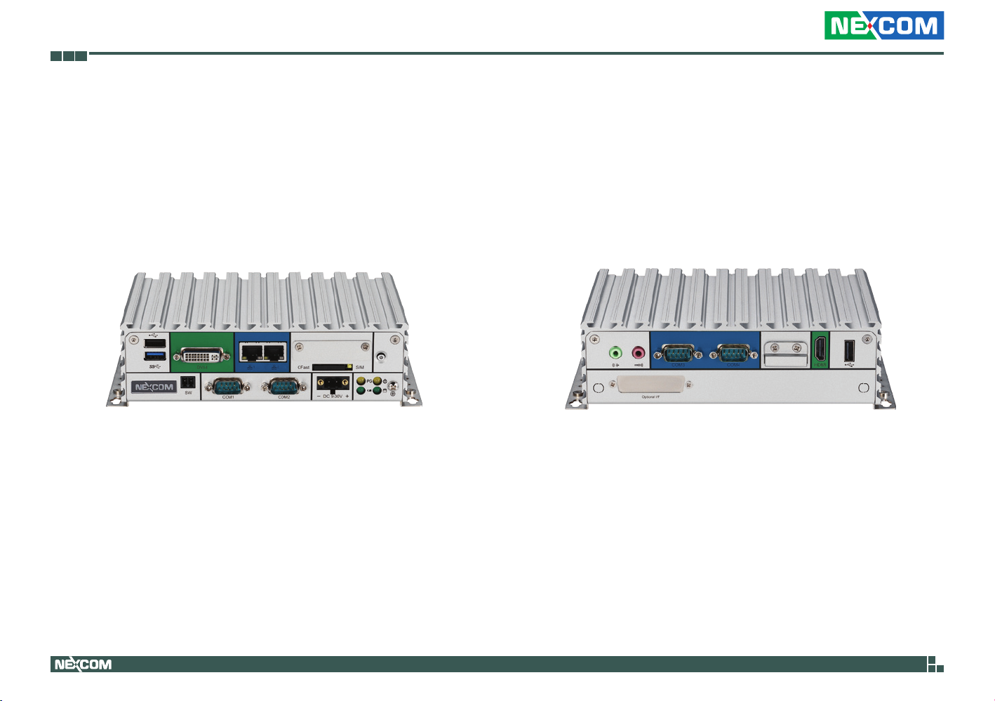
Knowing Your NISE 105
Front Panel
USB 2.0 DVI-I
Remote On/Off
USB 3.0
LAN Ports
COM1 and COM2
9-30V DC Input
CFast SIM
Power/HDD LEDs
GPIO/Battery LEDs
USB 2.0
USB 2.0 port to connect the system with USB 2.0/1.1 devices.
USB 3.0
USB 3.0 port to connect the system with USB 3.0/2.0 devices.
DVI-I
Used to connect a digital LCD panel.
Remote On/Off Switch
Used to connect a remote to power on/off the system.
LAN Ports
Two LAN ports used to connect the system to a local area network.
COM1 and COM2
Two DB9 ports used to connect RS232/422/485 compatible devices.
CFast Slot
Used to insert a CFast card.
SIM Slot
Used to insert a SIM card.
Power Button
9-30V DC Input
Used to plug a DC power cord.
Power/HDD LEDs
Indicates the power status and HDD activity of the system.
Copyright © 2013 NEXCOM International Co., Ltd. All Rights Reserved.
GPIO/Battery LEDs
Indicates the status of the battery and GPIO.
Power Button
Press to power-on or power-off the system.
4
NISE 105/105A User Manual

Chapter 1: Product Introduction
Rear Panel
Mic-in
Line-out
COM3 and COM4 Battery HDMI USB 2.0
Fieldbus
Line-out
Used to connect a headphone or a speaker.
Mic-in
Used to connect an external microphone.
COM3 and COM4
Two DB9 ports used to connect RS232/422/485 compatible devices.
Battery Slot
Used to hold an external battery.
HDMI
Used to connect a high-definition display.
USB 2.0
USB 2.0 port to connect the system with USB 2.0/1.1 devices.
Fieldbus
Expansion slot for add-on fieldbus modules.
Copyright © 2013 NEXCOM International Co., Ltd. All Rights Reserved.
5
NISE 105/105A User Manual

Chapter 1: Product Introduction
Mechanical Dimensions
Copyright © 2013 NEXCOM International Co., Ltd. All Rights Reserved.
185
194
206
256094
54
6
60
115
131
NISE 105/105A User Manual

Chapter 2: Jumpers and Connectors
Chapter 2: Jumpers and Connectors
This chapter describes how to set the jumpers and connectors on the
NISE 105 motherboard.
Before You Begin
▪ Ensure you have a stable, clean working environment. Dust and dirt can
get into components and cause a malfunction. Use containers to keep
small components separated.
▪ Adequate lighting and proper tools can prevent you from accidentally
damaging the internal components. Most of the procedures that follow
require only a few simple tools, including the following:
– A Philips screwdriver
– A flat-tipped screwdriver
– A set of jewelers screwdrivers
– A grounding strap
– An anti-static pad
▪ Using your fingers can disconnect most of the connections. It is
recommended that you do not use needle-nosed pliers to disconnect
connections as these can damage the soft metal or plastic parts of the
connectors.
▪ Before working on internal components, make sure that the power is off.
Ground yourself before touching any internal components, by touching
a metal object. Static electricity can damage many of the electronic
components. Humid environments tend to have less static electricity than
dry environments. A grounding strap is warranted whenever danger of
static electricity exists.
Precautions
Computer components and electronic circuit boards can be damaged by
discharges of static electricity. Working on computers that are still connected
to a power supply can be extremely dangerous.
Follow the guidelines below to avoid damage to your computer or yourself:
▪ Always disconnect the unit from the power outlet whenever you are
working inside the case.
▪ If possible, wear a grounded wrist strap when you are working inside the
computer case. Alternatively, discharge any static electricity by touching
the bare metal chassis of the unit case, or the bare metal body of any
other grounded appliance.
▪ Hold electronic circuit boards by the edges only. Do not touch the
components on the board unless it is necessary to do so. Don’t flex or
stress the circuit board.
▪ Leave all components inside the static-proof packaging that they shipped
with until they are ready for installation.
▪ Use correct screws and do not over tighten screws.
Copyright © 2013 NEXCOM International Co., Ltd. All Rights Reserved.
7
NISE 105/105A User Manual
Chapter 2: Jumpers and Connectors
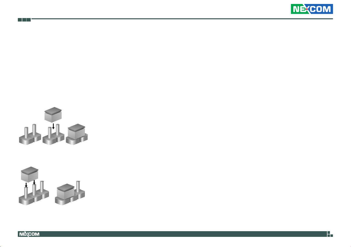
Jumper Settings
A jumper is the simplest kind of electric switch. It consists of two metal
pins and a cap. When setting the jumpers, ensure that the jumper caps are
placed on the correct pins. When the jumper cap is placed on both pins, the
jumper is short. If you remove the jumper cap, or place the jumper cap on
just one pin, the jumper is open.
Refer to the illustrations below for examples of what the 2-pin and 3-pin
jumpers look like when they are short (on) and open (off).
Two-Pin Jumpers: Open (Left) and Short (Right)
Three-Pin Jumpers: Pins 1 and 2 are Short
3
2
1
Copyright © 2013 NEXCOM International Co., Ltd. All Rights Reserved.
1
3
2
8
NISE 105/105A User Manual

Chapter 2: Jumpers and Connectors
NISE 105 System Components
The NISE 105 system is made up of a NISB 105 motherboard and an I/O daughterboard. This chapter lists the location and pinout assignment of the jumpers
and connectors on each component.
Locations of the Jumpers and Connectors for NISB 105
CN5
JP5
JP7
14
2
JP9
3
1
2
1
JFW1
6
JFW1
2
USB2.0
1
13
JP9
1
4
SW1
COM4
BAT1
BATTERY
BAT1
6
9
1
5
HDMI
CN6
4
H1
CN6
U22
53
51
49
47
45
43
41
39
37
35
5
1
33
31
29
27
25
23
21
19
17
15
13
11
9
7
R339
5
3
1
RUNGJLACE
BJBHBGBABCBEARAUAWALANACAEAGAJWAA
COM3
LINE OUT
MIC IN
4
6
CN2
CN2CN1
6
9
4
3
3
15
1
1
1
JP16
JP16
JP3
JP4
CN3
5
3184
2
CN3
BZ1
64
CN8
33
32
1
128
97
S1P17
65
96
U20
7
7
6
CN4
5
1
10
CN4
3184
JP13
JP8
J2
JP6
JP1
1
4
2
JP2
1
4
1
10
9
2
1
718
2
6
1
1
H5
CN7
CN9
10
9
USB2.0
USB3.0
Copyright © 2013 NEXCOM International Co., Ltd. All Rights Reserved.
JP10
3
1
2
JP11
4
3
JP11
13
D13
5
41
1
9
17
CN9
CN10
16
24
1
2
LAN1
CN10
DVI-I
B1A9
A1
A2
A10
LAN1
LAN2
LAN1
JP10
B9
B10B2
CFAST
9
SW2
SW2
JP12
3
1
NISE 105/105A User Manual

Chapter 2: Jumpers and Connectors
Jumpers
AT/ATX Pin Header
Connector type: 1x3 3-pin header, 2.0mm pitch
Connector location: JP5
1 3
Pin Function
1-2 AT
2-3* ATX
Copyright © 2013 NEXCOM International Co., Ltd. All Rights Reserved.
10
NISE 105/105A User Manual

Chapter 2: Jumpers and Connectors
Connector Pin Definitions
External I/O Interfaces - Front Panel
USB 3.0 and USB 2.0 Port
Connector type: USB 3.0 and USB 2.0 port
Connector location: CN9
1
13
5
Pin Definition Pin Definition
1 P5V_OC01_C 2 USB_0N_C
3 USB_0P_C 4 GND
5 USB3_RX0_N_C 6 USB3_RX0_P_C
7 GND 8 USB3_TX0_N_C
9 USB3_TX0_P_C 10 P5V_OC01_C
11 USB_1N_C 12 USB_1P_C
13 GND MH1 F_GND
MH2 F_GND MH3 F_GND
MH4 F_GND
4
9
8
DVI-I Connector
Connector type: 24-pin D-Sub, 2.0mm-M-180 (DVI)
Connector location: CN10
1 8
17 24
Pin Definition Pin Definition
1 TX2- 2 TX2+
3 GND 4 NC
5 NC 6 DDC_CLK
7 DDC_DATA 8 VSYNC_VGA
9 TX1- 10 TX1+
11 GND 12 NC
13 NC 14 DVI_VCC(+5V)
15 GND 16 HotPlugDet
17 TX0- 18 TX0+
19 GND 20 DDCCLK_VGA
21 DDCDATA_VGA 22 GND
23 TXCLK+ 24 TXCLKC1 RED C2 GREEN
C3 BLUE C4 HSYNC_VGA
C5A VGADET C5B GND
MH1 CHASSIS_GND MH2 CHASSIS_GND
Copyright © 2013 NEXCOM International Co., Ltd. All Rights Reserved.
11
NISE 105/105A User Manual
 Loading...