

Page 1

NEXCOM International Co., Ltd.
Industrial Computing Solutions
Fanless Computer
NISE 90
User Manual
NEXCOM International Co., Ltd.
Published August 2013
www.nexcom.com
Page 2

Content
Contents
Preface
Copyright ............................................................................................. iv
Disclaimer .............................................................................................. iv
Acknowledgements ............................................................................... iv
Regulatory Compliance Statements ........................................................ iv
Declaration of Conformity ...................................................................... iv
RoHS Compliance ................................................................................... v
Warranty and RMA ................................................................................ vi
Safety Information ................................................................................viii
Installation Recommendations ...............................................................viii
Safety Precautions .................................................................................. ix
Technical Support and Assistance ............................................................ x
Conventions Used in this Manual ............................................................ x
Global Service Contact Information ........................................................ xi
Package Contents ................................................................................. xiii
Ordering Information ............................................................................xiv
Chapter 1: Product Introduction
Overview ................................................................................................1
Key Features ...........................................................................................1
Hardware Specifications ..........................................................................2
Knowing Your NISE 90 ............................................................................ 3
Mechanical Dimensions ...........................................................................5
NISE 90 ...............................................................................................5
Chapter 2: Jumpers and Connectors
Before You Begin ....................................................................................6
Precautions ............................................................................................6
Jumper Settings ......................................................................................7
Locations of the Jumpers and Connectors for NISB 90 ............................. 8
Jumpers .................................................................................................. 9
RTC Clear Pin Header ..........................................................................9
LVDS Backlight Power Select Pin Header ..............................................9
Connector Pin Definitions .....................................................................10
External I/O Interfaces – Front Panel ................................................... 10
LAN1 and LAN2 Ports .....................................................................10
USB0, USB1 and USB2 Ports ........................................................... 11
CAN Bus and COM1 Connector ..................................................... 11
COM3 and COM2 Connector ........................................................12
External I/O Interfaces – Rear Panel .................................................... 12
VGA Connector .............................................................................12
GPI & GPO Connector .................................................................... 13
9~36V DC Power Input .................................................................. 14
Internal Connectors ........................................................................... 15
System FAN Connector ...................................................................15
LVDS Panel Backlight Connector ..................................................... 15
LVDS Connector ............................................................................. 16
USB 3/4 Connector ........................................................................16
PWR_BT/RET_BT/LED/SMBUS Pin Header ........................................17
Mic-in Pin Header ...........................................................................17
Line-in Pin Header .......................................................................... 18
Copyright © 2013 NEXCOM International Co., Ltd. All Rights Reserved.
ii
NISE 90 User Manual
Page 3

Content
Line-out Pin Header ........................................................................18
PoE Power Connector ....................................................................19
SATA0 Connector ...........................................................................19
SATA1 Connector ...........................................................................20
SATA Power Connector ..................................................................20
SATA-DOM Power Connector .........................................................21
Keyboard / Mouse Pin Header ........................................................21
COM4 Box Pin Header ...................................................................22
SIM Card Connector ......................................................................22
Mini-PCIe Connector ...................................................................... 23
Chapter 3: System Setup
Removing the Chassis Cover .................................................................24
Installing a SATA Hard Drive ..................................................................25
Installing a Wireless LAN Module (half-size) ........................................... 27
Installing a SIM Card .............................................................................29
Chapter 4: BIOS Setup
About BIOS Setup ................................................................................. 31
When to Configure the BIOS .................................................................31
Default Configuration ........................................................................... 32
Entering Setup ...................................................................................... 32
Legends ................................................................................................ 32
BIOS Setup Utility .................................................................................. 34
Main .................................................................................................34
Advanced .......................................................................................... 35
Chipset ..............................................................................................43
Boot .................................................................................................. 45
Security .............................................................................................47
Save & Exit ........................................................................................47
Appendix A: Power Consumption...............................49
Appendix B: GPI/O Programming Guide.....................51
Appendix C: Watchdog Timer......................................52
Copyright © 2013 NEXCOM International Co., Ltd. All Rights Reserved.
iii
NISE 90 User Manual
Page 4

Preface
Preface
Copyright
This publication, including all photographs, illustrations and software, is
protected under international copyright laws, with all rights reserved. No
part of this manual may be reproduced, copied, translated or transmitted in
any form or by any means without the prior written consent from NEXCOM
International Co., Ltd.
Disclaimer
The information in this document is subject to change without prior notice and
does not represent commitment from NEXCOM International Co., Ltd. However,
users may update their knowledge of any product in use by constantly checking
its manual posted on our website: http://www.nexcom.com. NEXCOM shall
not be liable for direct, indirect, special, incidental, or consequential damages
arising out of the use of any product, nor for any infringements upon the rights
of third parties, which may result from such use. Any implied warranties of
merchantability or fitness for any particular purpose is also disclaimed.
Acknowledgements
NISE 90 is a trademark of NEXCOM International Co., Ltd. All other product
names mentioned herein are registered trademarks of their respective
owners.
Regulatory Compliance Statements
This section provides the FCC compliance statement for Class B devices and
describes how to keep the system CE compliant.
Declaration of Conformity
FCC
This equipment has been tested and verified to comply with the limits for
a Class B digital device, pursuant to Part 15 of FCC Rules. These limits are
designed to provide reasonable protection against harmful interference when
the equipment is operated in a commercial environment. This equipment
generates, uses, and can radiate radio frequency energy and, if not installed
and used in accordance with the instructions, may cause harmful interference
to radio communications. Operation of this equipment in a residential area
(domestic environment) is likely to cause harmful interference, in which
case the user will be required to correct the interference (take adequate
measures) at their own expense.
CE
The product(s) described in this manual complies with all applicable
European Union (CE) directives if it has a CE marking. For computer systems
to remain CE compliant, only CE-compliant parts may be used. Maintaining
CE compliance also requires proper cable and cabling techniques.
Copyright © 2013 NEXCOM International Co., Ltd. All Rights Reserved.
iv
NISE 90 User Manual
Page 5

Preface
RoHS Compliance
NEXCOM RoHS Environmental Policy and Status
Update
This publication, including all photographs, illustrations
and software, is protected under international copyright
laws, with all rights reserved. No part of this manual
may be reproduced, copied, translated or transmitted in any form or by any
means without the prior written consent from NEXCOM International Co.,
Ltd.
RoHS restricts the use of Lead (Pb) < 0.1% or 1,000ppm, Mercury (Hg) < 0.1%
or 1,000ppm, Cadmium (Cd) < 0.01% or 100ppm, Hexavalent Chromium
(Cr6+) < 0.1% or 1,000ppm, Polybrominated biphenyls (PBB) < 0.1% or
1,000ppm, and Polybrominated diphenyl Ethers (PBDE) < 0.1% or 1,000ppm.
In order to meet the RoHS compliant directives, NEXCOM has established
an engineering and manufacturing task force to implement the introduction
of green products. The task force will ensure that we follow the standard
NEXCOM development procedure and that all the new RoHS components
and new manufacturing processes maintain the highest industry quality
levels for which NEXCOM are renowned.
The model selection criteria will be based on market demand. Vendors and
suppliers will ensure that all designed components will be RoHS compliant.
How to recognize NEXCOM RoHS Products?
For existing products where there are non-RoHS and RoHS versions, the
suffix “(LF)” will be added to the compliant product name.
All new product models launched after January 2006 will be RoHS compliant.
They will use the usual NEXCOM naming convention.
Copyright © 2013 NEXCOM International Co., Ltd. All Rights Reserved.
v
NISE 90 User Manual
Page 6

Preface
Warranty and RMA
NEXCOM Warranty Period
NEXCOM manufactures products that are new or equivalent to new in
accordance with industry standard. NEXCOM warrants that products will
be free from defect in material and workmanship for 2 years, beginning on
the date of invoice by NEXCOM. HCP series products (Blade Server) which
are manufactured by NEXCOM are covered by a three year warranty period.
NEXCOM Return Merchandise Authorization (RMA)
▪ Customers shall enclose the “NEXCOM RMA Service Form” with the
returned packages.
▪ Customers must collect all the information about the problems
encountered and note anything abnormal or, print out any on-screen
messages, and describe the problems on the “NEXCOM RMA Service
Form” for the RMA number apply process.
▪ Customers can send back the faulty products with or without accessories
(manuals, cable, etc.) and any components from the card, such as CPU
and RAM. If the components were suspected as part of the problems,
please note clearly which components are included. Otherwise, NEXCOM
is not responsible for the devices/parts.
▪ Customers are responsible for the safe packaging of defective products,
making sure it is durable enough to be resistant against further damage
and deterioration during transportation. In case of damages occurred
during transportation, the repair is treated as “Out of Warranty.”
▪ Any products returned by NEXCOM to other locations besides the
customers’ site will bear an extra charge and will be billed to the customer.
Repair Service Charges for Out-of-Warranty Products
NEXCOM will charge for out-of-warranty products in two categories, one is
basic diagnostic fee and another is component (product) fee.
Repair Service Charges for Out-of-Warranty Products
NEXCOM will charge for out-of-warranty products in two categories, one is
basic diagnostic fee and another is component (product) fee.
System Level
▪ Component fee: NEXCOM will only charge for main components such as
SMD chip, BGA chip, etc. Passive components will be repaired for free,
ex: resistor, capacitor.
▪ Items will be replaced with NEXCOM products if the original one cannot
be repaired. Ex: motherboard, power supply, etc.
▪ Replace with 3rd party products if needed.
▪ If RMA goods can not be repaired, NEXCOM will return it to the customer
without any charge.
Board Level
▪ Component fee: NEXCOM will only charge for main components, such
as SMD chip, BGA chip, etc. Passive components will be repaired for free,
ex: resistors, capacitors.
▪ If RMA goods can not be repaired, NEXCOM will return it to the customer
without any charge.
Copyright © 2013 NEXCOM International Co., Ltd. All Rights Reserved.
vi
NISE 90 User Manual
Page 7

Preface
Warnings
Read and adhere to all warnings, cautions, and notices in this guide and
the documentation supplied with the chassis, power supply, and accessory
modules. If the instructions for the chassis and power supply are inconsistent
with these instructions or the instructions for accessory modules, contact
the supplier to find out how you can ensure that your computer meets
safety and regulatory requirements.
Cautions
Electrostatic discharge (ESD) can damage system components. Do the
described procedures only at an ESD workstation. If no such station is
available, you can provide some ESD protection by wearing an antistatic
wrist strap and attaching it to a metal part of the computer chassis.
Copyright © 2013 NEXCOM International Co., Ltd. All Rights Reserved.
vii
NISE 90 User Manual
Page 8

Preface
Safety Information
Before installing and using the device, note the following precautions:
▪ Read all instructions carefully.
▪ Do not place the unit on an unstable surface, cart, or stand.
▪ Follow all warnings and cautions in this manual.
▪ When replacing parts, ensure that your service technician uses parts
specified by the manufacturer.
▪ Avoid using the system near water, in direct sunlight, or near a heating
device.
▪ The load of the system unit does not solely rely for support from the
rackmounts located on the sides. Firm support from the bottom is highly
necessary in order to provide balance stability.
▪ The computer is provided with a battery-powered real-time clock circuit.
There is a danger of explosion if battery is incorrectly replaced. Replace
only with the same or equivalent type recommended by the manufacturer.
Discard used batteries according to the manufacturer’s instructions.
Installation Recommendations
Ensure you have a stable, clean working environment. Dust and dirt can get
into components and cause a malfunction. Use containers to keep small
components separated.
Adequate lighting and proper tools can prevent you from accidentally
damaging the internal components. Most of the procedures that follow
require only a few simple tools, including the following:
▪ A Philips screwdriver
▪ A flat-tipped screwdriver
▪ A grounding strap
▪ An anti-static pad
Using your fingers can disconnect most of the connections. It is recommended
that you do not use needle-nose pliers to disconnect connections as these
can damage the soft metal or plastic parts of the connectors.
Copyright © 2013 NEXCOM International Co., Ltd. All Rights Reserved.
viii
NISE 90 User Manual
Page 9

Preface
Safety Precautions
1. Read these safety instructions carefully.
2. Keep this User Manual for later reference.
3. Disconnect this equipment from any AC outlet before cleaning. Use a
damp cloth. Do not use liquid or spray detergents for cleaning.
4. For plug-in equipment, the power outlet socket must be located near the
equipment and must be easily accessible.
5. Keep this equipment away from humidity.
6. Put this equipment on a stable surface during installation. Dropping it or
letting it fall may cause damage.
7. The openings on the enclosure are for air convection to protect the
equipment from overheating. DO NOT COVER THE OPENINGS.
8. Make sure the voltage of the power source is correct before connecting
the equipment to the power outlet.
9. Place the power cord in a way so that people will not step on it. Do not
place anything on top of the power cord. Use a power cord that has been
approved for use with the product and that it matches the voltage and
current marked on the product’s electrical range label. The voltage and
current rating of the cord must be greater than the voltage and current
rating marked on the product.
10. All cautions and warnings on the equipment should be noted.
11. If the equipment is not used for a long time, disconnect it from the
power source to avoid damage by transient overvoltage.
12. Never pour any liquid into an opening. This may cause fire or electrical
shock.
13. Never open the equipment. For safety reasons, the equipment should be
opened only by qualified service personnel.
14. If one of the following situations arises, get the equipment checked by
service personnel:
a. The power cord or plug is damaged.
b. Liquid has penetrated into the equipment.
c. The equipment has been exposed to moisture.
d. The equipment does not work well, or you cannot get it to work
according to the user’s manual.
e. The equipment has been dropped and damaged.
f. The equipment has obvious signs of breakage.
15. Do not place heavy objects on the equipment.
16. The unit uses a three-wire ground cable which is equipped with a third
pin to ground the unit and prevent electric shock. Do not defeat the
purpose of this pin. If your outlet does not support this kind of plug,
contact your electrician to replace your obsolete outlet.
17. CAUTION: DANGER OF EXPLOSION IF BATTERY IS INCORRECTLY
REPLACED. REPLACE ONLY WITH THE SAME OR EQUIVALENT TYPE
RECOMMENDED BY THE MANUFACTURER. DISCARD USED BATTERIES
ACCORDING TO THE MANUFACTURER’S INSTRUCTIONS.
Copyright © 2013 NEXCOM International Co., Ltd. All Rights Reserved.
ix
NISE 90 User Manual
Page 10
Preface
CAUTION!
Technical Support and Assistance
1. For the most updated information of NEXCOM products, visit NEXCOM’s
website at www.nexcom.com.
2. For technical issues that require contacting our technical support team or
sales representative, please have the following information ready before
calling:
– Product name and serial number
– Detailed information of the peripheral devices
– Detailed information of the installed software (operating system,
version, application software, etc.)
– A complete description of the problem
– The exact wordings of the error messages
Warning!
1. Handling the unit: carry the unit with both hands and handle it with care.
2. Maintenance: to keep the unit clean, use only approved cleaning products
or clean with a dry cloth.
3. CompactFlash: Turn off the unit’s power before inserting or removing a
CompactFlash storage card.
Conventions Used in this Manual
Warning:
Information about certain situations, which if not observed,
can cause personal injury. This will prevent injury to yourself
when performing a task.
CAUTION!CAUTION!
Caution:
Information to avoid damaging components or losing data.
Note:
Provides additional information to complete a task easily.
Copyright © 2013 NEXCOM International Co., Ltd. All Rights Reserved.
x
NISE 90 User Manual
Page 11

Preface
Global Service Contact Information
Headquarters
NEXCOM International Co., Ltd.
15F, No. 920, Chung-Cheng Rd., ZhongHe
District, New Taipei City, 23586, Taiwan,
R.O.C.
Tel: +886-2-8226-7786
Fax: +886-2-8226-7782
www.nexcom.com.tw
America
USA
NEXCOM USA
2883 Bayview Drive,
Fremont CA 94538, USA
Tel: +1-510-656-2248
Fax: +1-510-656-2158
Email: [email protected]
www.nexcom.com
Asia
Taiwan
Taichung Office
16F, No.250, Sec. 2,
Chongde Rd., Beitun Dist.,
Taichung City 406, R.O.C.
Tel: +886-4-2249-1179
Fax: +886-4-2249-1172
www.nexcom.com.tw
NEXCOM Japan
9F, Tamachi Hara Bldg.,4-11-5, Shiba
Minato-ku,
Tokyo, 108-0014, Japan
Tel: +81-3-5419-7830
Fax: +81-3-5419-7832
Email: [email protected]
www.nexcom-jp.com
China
NEXCOM China
2F, Block 4, Venus Plaza, Building 21,
ZhongGuanCun Software Park, No.8,
Dongbeiwang West Road, Haidian District,
Beijing, 100193, China
Tel: +86-10-8282-5880
Fax: +86-10-8282-5955
Email: [email protected]
www.nexcom.cn
Shanghai Office
Room 1505, Greenland He Chuang Bldg.,
No. 450 Caoyang Rd.,
Shanghai, 200062, China
Tel: +86-21-6150-8008
Fax: +86-21-3251-6358
Email: [email protected]
www.nexcom.cn
Nanjing Office
Hall C, Block 17, Tian Xing Cui Lang Bldg.,
No. 49 Yunnan North Rd.,
Nanjing, 210018, China
Tel: +86-25-8315-3486
Fax: +86-25-8315-3489
Email: [email protected]
www.nexcom.cn
Shenzhen Office
Western Room 708, Block 210,
Tairan Industry & Trading Place, Futian Area,
Shenzhen, 518040, China
Tel: +86-755-833 7203
Fax: +86-755-833 7213
Email: [email protected]
www.nexcom.cn
Wuhan Office
1-C1804/1805,Mingze Liwan, No.519
South Luoshi Rd,Hongshan District,
Wuhan,430070,China
Tel: +86-27-8722-7400
Fax: +86-27-8722-7400
Email: [email protected]
www.nexcom.cn
Copyright © 2013 NEXCOM International Co., Ltd. All Rights Reserved.
xi
NISE 90 User Manual
Page 12

Preface
Chengdu Office
9F, Shuxiangxie, Xuefu Garden,
No.12 Section 1, South Yihuan Rd.,
Chengdu, 610061, China
Tel: +86-28-8523-0186
Fax: +86-28-8523-0186
Email: [email protected]
www.nexcom.cn
Europe
France
NEXCOM France
La Grande Arche-Paroi Nord
92044 Paris La Défense
France
Tel: +33 (0) 1 40 90 33 35
Fax: +33 (0) 1 40 90 31 01
Email: [email protected]
www.nexcom.eu
Germany
NEXCOM GmbH
Leopoldstraße Business Centre,
Leopoldstraße 244,
80807 Munich, Germany
Tel: +49-89-208039-278
Fax: +49-89-208039-279
Email: [email protected]
www.nexcom.eu
Italy
NEXCOM ITALIA S.r.l
Via Gaudenzio Ferrari 29,
21047 Saronno (VA), Italia
Tel: +39 02 9628 0333
Fax: +39 02 9286 9215
Email: [email protected]
www.nexcomitalia.it
United Kingdom
NEXCOM EUROPE
10 Vincent Avenue,
Crownhill Business Centre,
Milton Keynes, Buckinghamshire
MK8 0AB, United Kingdom
Tel: +44-1908-267121
Fax: +44-1908-262042
Email: [email protected]
www.nexcom.eu
Copyright © 2013 NEXCOM International Co., Ltd. All Rights Reserved.
xii
NISE 90 User Manual
Page 13
Preface
Package Contents
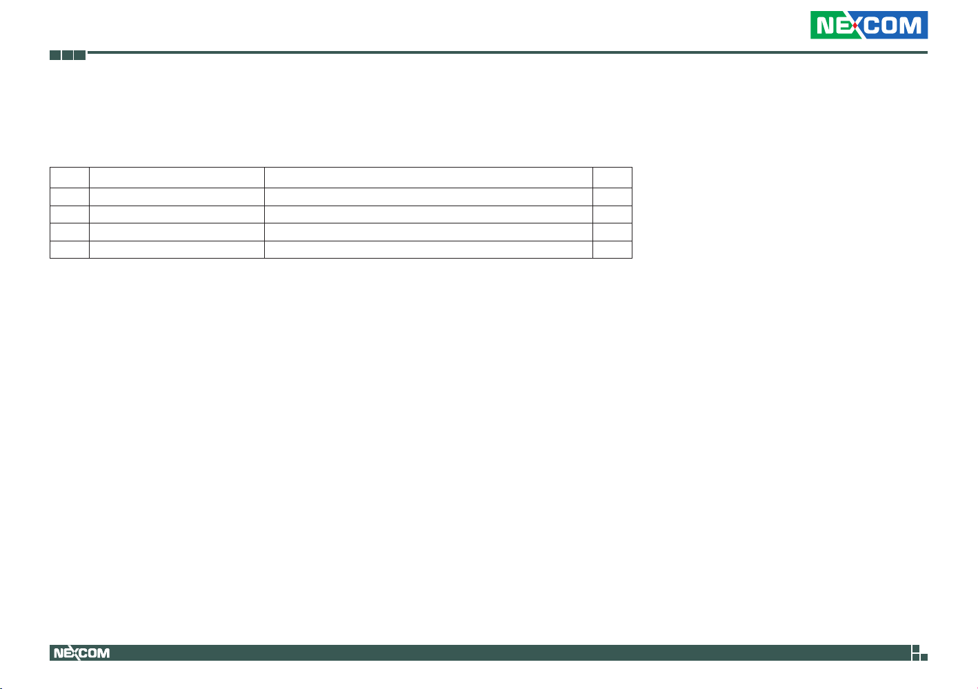
Before continuing, verify that the NISE 90 package that you received is complete. Your package should have all the items listed in the following table.
Item Part Number Name Qty
1 4NCPM00302X00 Terminal Blocks 3P Phoenix Contact:1777992 1
2 50311F0110X00 Flat Head Screw Long FEI:F3x5ISO+NYLOK NIGP 4
3 60177A0238X00 NISB90 Quick Reference Guide 1
4 602DCD0428X00 NISE90 CD Driver 1
Copyright © 2013 NEXCOM International Co., Ltd. All Rights Reserved.
xiii
NISE 90 User Manual
Page 14

Preface
Ordering Information
The following information below provides ordering information for NISE 90.
• Barebone
- NISE 90 (P/N: 10J00009000X0)
Intel Atom E620 0.6GHz DIN Rail Fanless System with 512MB Memory onboard
- NISE 91 (P/N: 10J00009100X0)
Intel Atom E640 1.0GHz DIN Rail Fanless System with 1G Memory onboard
Copyright © 2013 NEXCOM International Co., Ltd. All Rights Reserved.
xiv
NISE 90 User Manual
Page 15
Chapter 1: Product Introduction
Chapter 1: Product Introduction
Overview
Key Features
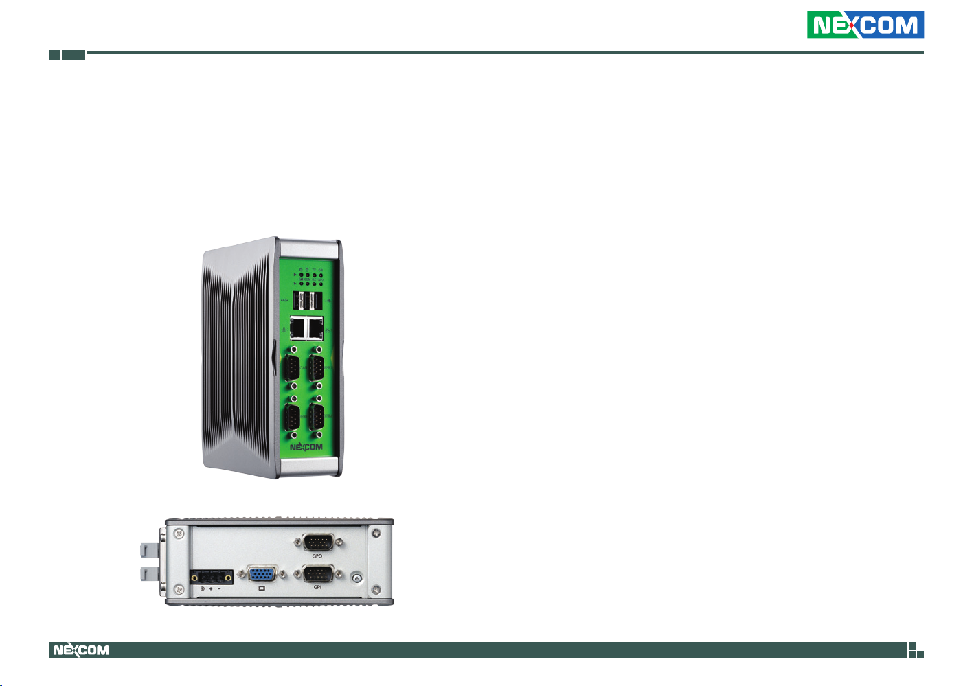
▪ On-board Intel® Atom™ E620 processor, 0.6GHz
▪ On-board DDR2 512MB memory chip
®
▪ 2x Intel
▪ 3x USB2.0 / 1x VGA / 3x Serial Ports / 1x CAN bus
▪ 8CH GPI and 8CH GPO
▪ Support 1x 2.5” HDD drive bay
▪ Support 12V and 24VDC input
GbE LANs
Copyright © 2013 NEXCOM International Co., Ltd. All Rights Reserved.
1
NISE 90 User Manual
Page 16

Chapter 1: Product Introduction
Hardware Specifications
CPU Support
▪ On-board Intel® Atom™ Tunnel Creek E620 processor, 0.6GHz 512K Cache
▪ On-board Chipset: Intel
Main Memory
▪ On-board DDR2 512MB memory chip, unbuffered and non-ECC support
Storage Device
▪ 1x 2.5” SATA HDD drive bay for optional SSD or HDD
▪ Support optional SATA DOM, horizontal type only
I/O Interface-Front
▪ 3x USB ports
▪ 2x RJ45 GbE LAN ports, Intel 82574L controller on-board
Support LAN teaming function
▪ 3x DB9 serial ports
COM1: Support RS232/422/485 (Selected on BIOS menu)
COM2: Support RS232 only
COM3: Support RS232 only
▪ 1x DB9 CAN Bus
- Support CAN 2.0b protocol
- Support both 11-bit and 26-bit identifiers
- Support bit rates up to 1Mbps
- Clock frequency of 40MHz
I/O Interface-Bottom
▪ 1x DB15 VGA port
®
EG20T
▪ 1x DB15 male connector for 8CH General Purpose Input
▪ 1x DB15 male connector for 8CH General Purpose Output
▪ 3-pin DC input, support 12VDC input and 24VDC input
▪ 1x Power on/off switch
Supported OS
▪ Windows XP
▪ Windows Embedded Standard 2009
▪ Fedora 14 (Kernnel 2.6)
System Dimension
▪ 59mm (W) x 140mm (D) x167mm (H)
Construction
▪ Aluminum chassis with fanless design
Environment
▪ Operating temperature:
Ambient with air flow: -5°C to 55°C
(According to IEC60068-2-1, IEC60068-2-2, IEC60068-2-14)
▪ Storage temperature: -20°C to 80°C
▪ Relative humidity: 10% to 93% (non-condensing)
▪ Shock protection: 20G, half sine, 11ms, IEC60068-2-27
▪ Vibration protection
- Random: 0.3Grms @ 5~500 Hz according to IEC60068-2-64
- Sinusoidal: 0.3Grms @ 5~500 Hz according to IEC60068-2-6
Certifications
▪ CE approval
▪ FCC Class A
Copyright © 2013 NEXCOM International Co., Ltd. All Rights Reserved.
2
NISE 90 User Manual
Page 17
Chapter 1: Product Introduction
Knowing Your NISE 90
Front Panel
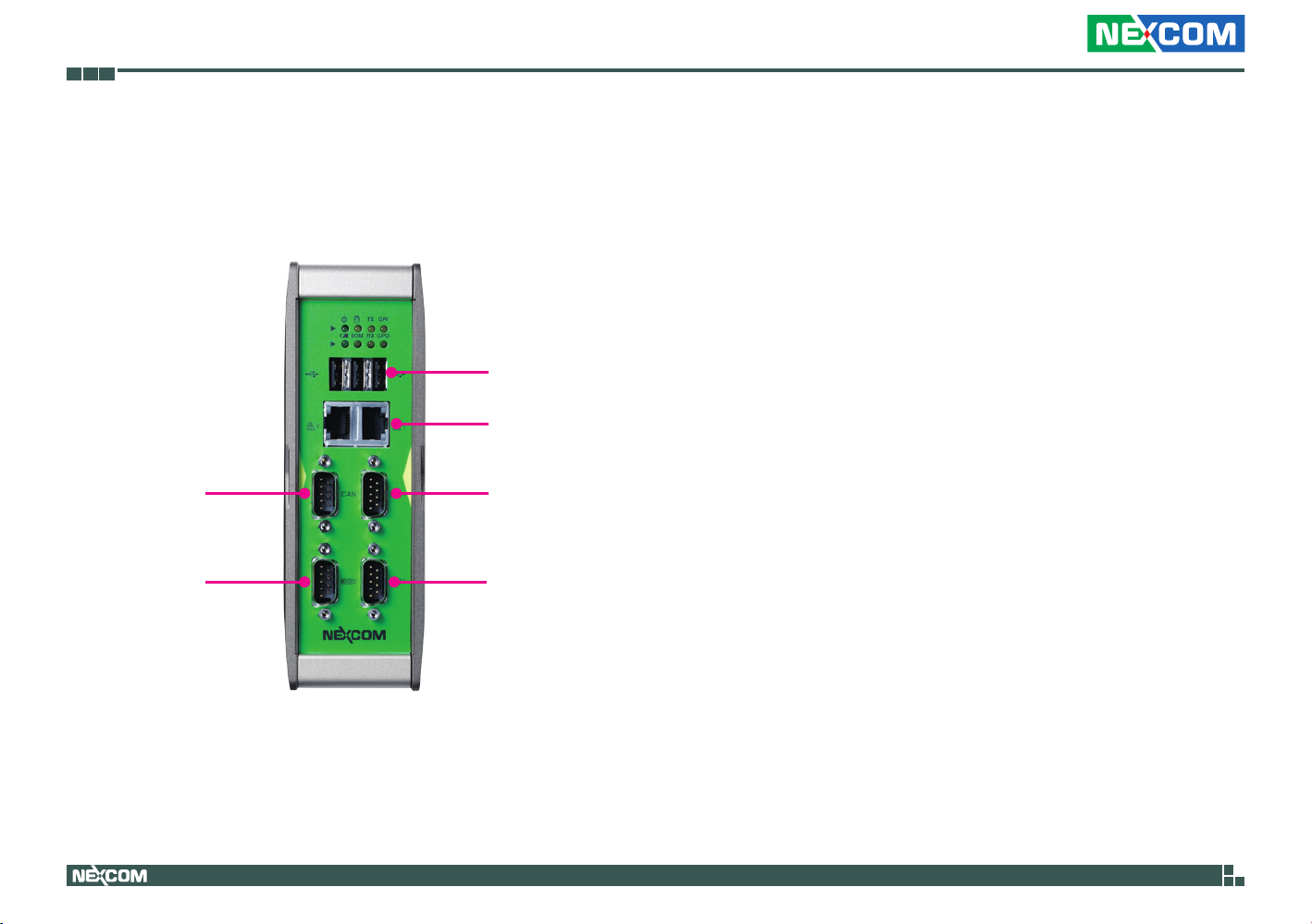
USB 2.0
USB2.0 Ports
Triple USB2.0 ports to connect the system with USB2.0/1.1 devices.
CAN Bus and COM1 RS232/RS422/RS485
DB-9 CAN bus connector and serial port used to connect RS232/422/485
compatible serial devices.
CAN bus
COM 3
Copyright © 2013 NEXCOM International Co., Ltd. All Rights Reserved.
LAN
COM 1
COM 2
COM3 and COM2
Serial ports used to connect RS232 compatible devices.
LED Indicators
Two LEDs for HDD access and power status of the system. Two LEDs
indicators for COM port TX and RX signals, two programmable GPIO LEDs
and a LED for battery power, replace battery when this LED is active.
3
NISE 90 User Manual
Page 18
Chapter 1: Product Introduction
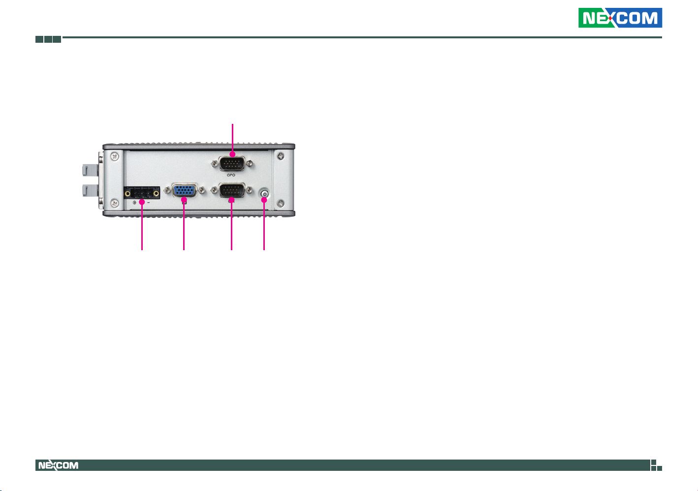
Rear Panel
12C/24V DC Input
GPO
VGA GPI Power Button
12/24V DC Input
3-pin terminal block connector used to plug to a DC power supply.
GPO and GPI
The GPO and GPI connectors support 8-channel GPO and 8-channel GPI.
VGA
Used to connect an analog VGA monitor.
Power Button
Press to power-on or power-off the system.
Copyright © 2013 NEXCOM International Co., Ltd. All Rights Reserved.
4
NISE 90 User Manual
Page 19
Chapter 1: Product Introduction
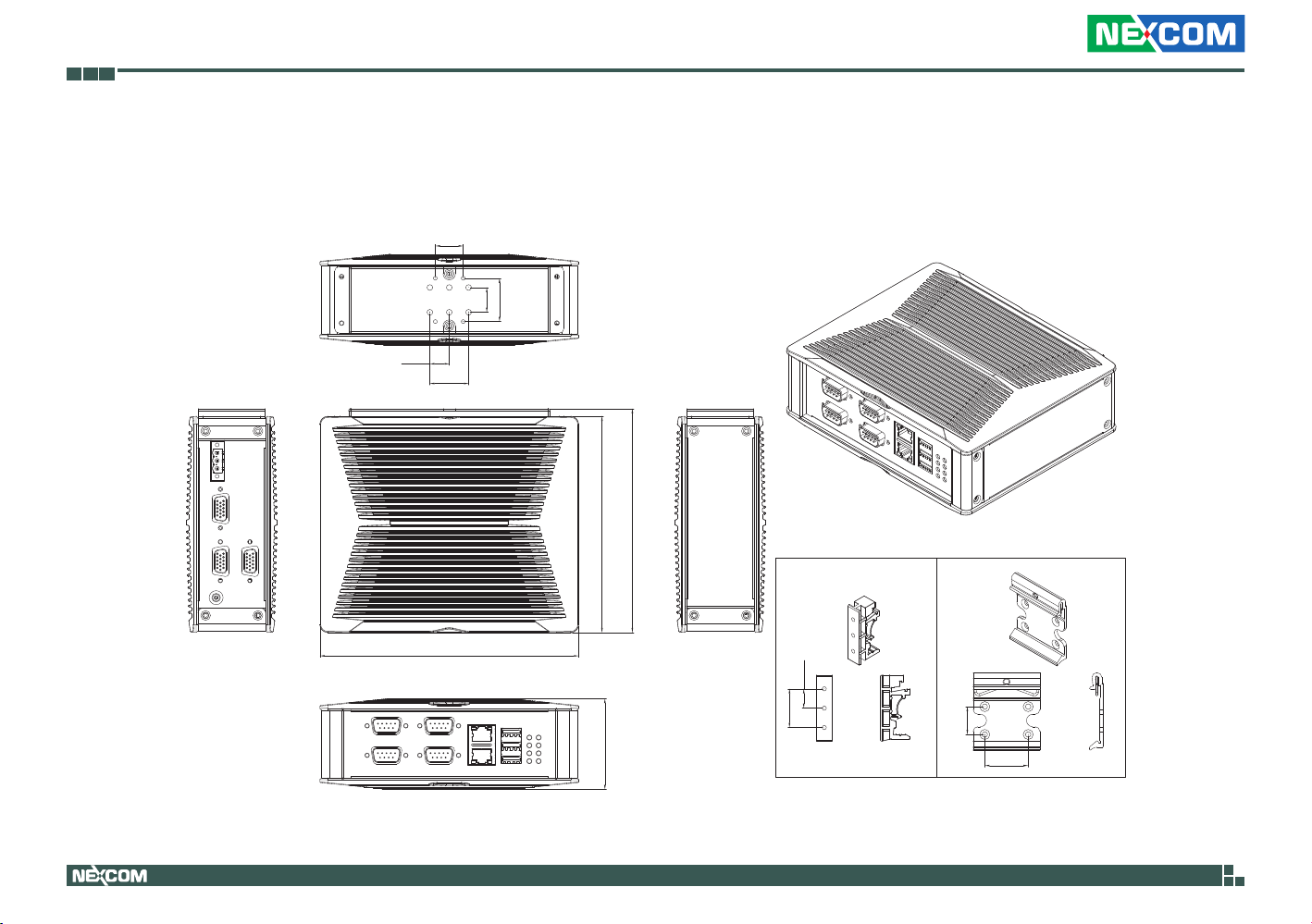
Mechanical Dimensions
NISE 90
12.50
18.00
25.00
16.00
28.00
139.60
144.60
DIN RAIL CLIP
A B
Copyright © 2013 NEXCOM International Co., Ltd. All Rights Reserved.
167.00
58.79
12.50
25.00
5
18.00
28.00
NISE 90 User Manual
Page 20

Chapter 2: Jumpers and Connectors
Chapter 2: Jumpers and Connectors
This chapter describes how to set the jumpers and connectors on the
NISE 90 motherboard.
Before You Begin
▪ Ensure you have a stable, clean working environment. Dust and dirt can
get into components and cause a malfunction. Use containers to keep
small components separated.
▪ Adequate lighting and proper tools can prevent you from accidentally
damaging the internal components. Most of the procedures that follow
require only a few simple tools, including the following:
– A Philips screwdriver
– A flat-tipped screwdriver
– A set of jewelers screwdrivers
– A grounding strap
– An anti-static pad
▪ Using your fingers can disconnect most of the connections. It is
recommended that you do not use needle-nosed pliers to disconnect
connections as these can damage the soft metal or plastic parts of the
connectors.
▪ Before working on internal components, make sure that the power is off.
Ground yourself before touching any internal components, by touching
a metal object. Static electricity can damage many of the electronic
components. Humid environments tend to have less static electricity than
dry environments. A grounding strap is warranted whenever danger of
static electricity exists.
Precautions
Computer components and electronic circuit boards can be damaged by
discharges of static electricity. Working on computers that are still connected
to a power supply can be extremely dangerous.
Follow the guidelines below to avoid damage to your computer or yourself:
▪ Always disconnect the unit from the power outlet whenever you are
working inside the case.
▪ If possible, wear a grounded wrist strap when you are working inside the
computer case. Alternatively, discharge any static electricity by touching
the bare metal chassis of the unit case, or the bare metal body of any
other grounded appliance.
▪ Hold electronic circuit boards by the edges only. Do not touch the
components on the board unless it is necessary to do so. Don’t flex or
stress the circuit board.
▪ Leave all components inside the static-proof packaging that they shipped
with until they are ready for installation.
▪ Use correct screws and do not over tighten screws.
Copyright © 2013 NEXCOM International Co., Ltd. All Rights Reserved.
6
NISE 90 User Manual
Page 21
Chapter 2: Jumpers and Connectors
Jumper Settings
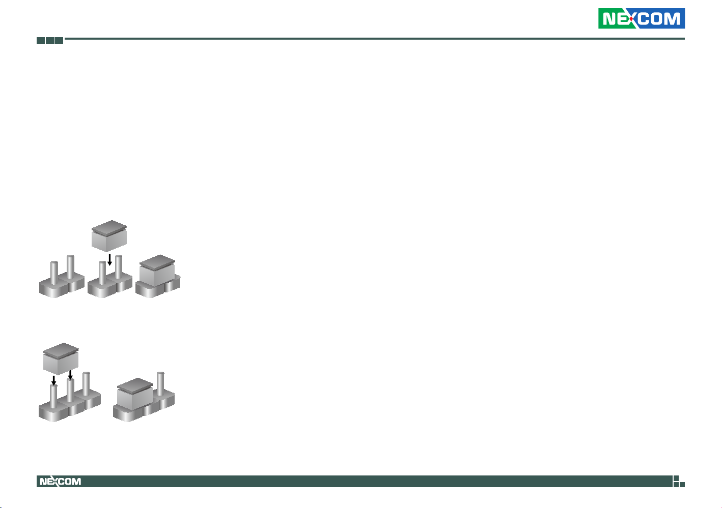
A jumper is the simplest kind of electric switch. It consists of two metal
pins and a cap. When setting the jumpers, ensure that the jumper caps are
placed on the correct pins. When the jumper cap is placed on both pins, the
jumper is short. If you remove the jumper cap, or place the jumper cap on
just one pin, the jumper is open.
Refer to the illustrations below for examples of what the 2-pin and 3-pin
jumpers look like when they are short (on) and open (off).
Two-Pin Jumpers: Open (Left) and Short (Right)
Three-Pin Jumpers: Pins 1 and 2 are Short
3
2
1
Copyright © 2013 NEXCOM International Co., Ltd. All Rights Reserved.
1
3
2
7
NISE 90 User Manual
Page 22
Chapter 2: Jumpers and Connectors
J5
CN5
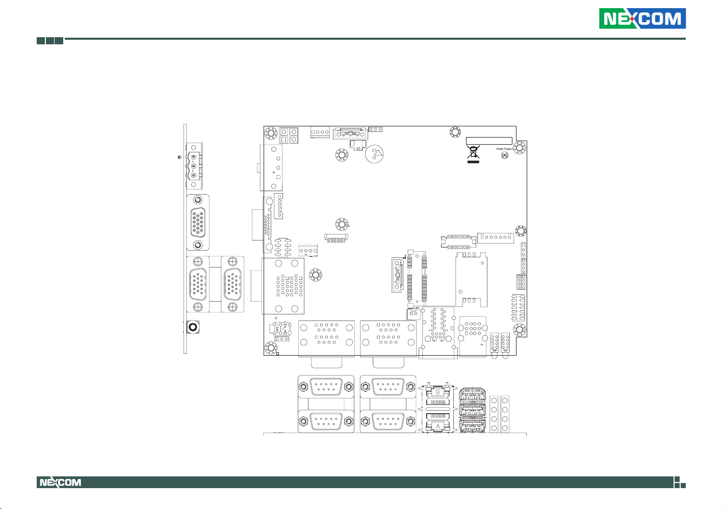
Locations of the Jumpers and Connectors for NISB 90
The figure below shows the location of the jumpers and connectors.
7
1
J5
CN5
4
C223
H5
H2
J16
J16
1
5
1410
18
1
1
2
J17
COM1
JP5
3
BZ1
R58
1
J4
7
15
17
J4
1
51
1
J8
J8
1
5
69
14
10
15
18
CN3
2
16
CN3
18
52
C720
A10 B10
A1
B11
A11
COP1
Y
214
H1
CN1
+
–
VGA
GPO
GPI
3
CN2
J9
1
VGA1
5
15
10
14
3
8
12
1
J2
11
6
1
VGA2
21
26
30
SW1
JP2
H4
13
K
K
CN2
D
1
J9
6
U59
16
20
J2
C9
FB1
87
U1
CN1
2
C10
11
15
G
10625
COM2
1
J1
J1
4
R900
1
H3
5
1
69
15
10
U65
H10
NISB90
REV:C
4BJ00090C1X10
MADE IN TAIWAN
H7
H9
1
19
20
IDE1
CT12
12
9
14
A4
A3
A2
A1
J6
7
J6
JP12
1
JP12
3
1
JP9
JP9
4
1
JP10
JP13
JP13JP10
414
1
2
JP1
JP1
14
13
Q11Q5
C127
H6
C4
R877
A4
C4
C3
A3
C3
C2
A2
C2
C1
A1
C1
LED1
LED2
CN4
CN4
1
2
IDE1
F6
B1
B14
A14
G
USB1
Copyright © 2013 NEXCOM International Co., Ltd. All Rights Reserved.
COM3
COM2
CAN
LAN2
COM1
LAN1
USB0
USB1
USB2
8
NISE 90 User Manual
Page 23
Chapter 2: Jumpers and Connectors
Jumpers
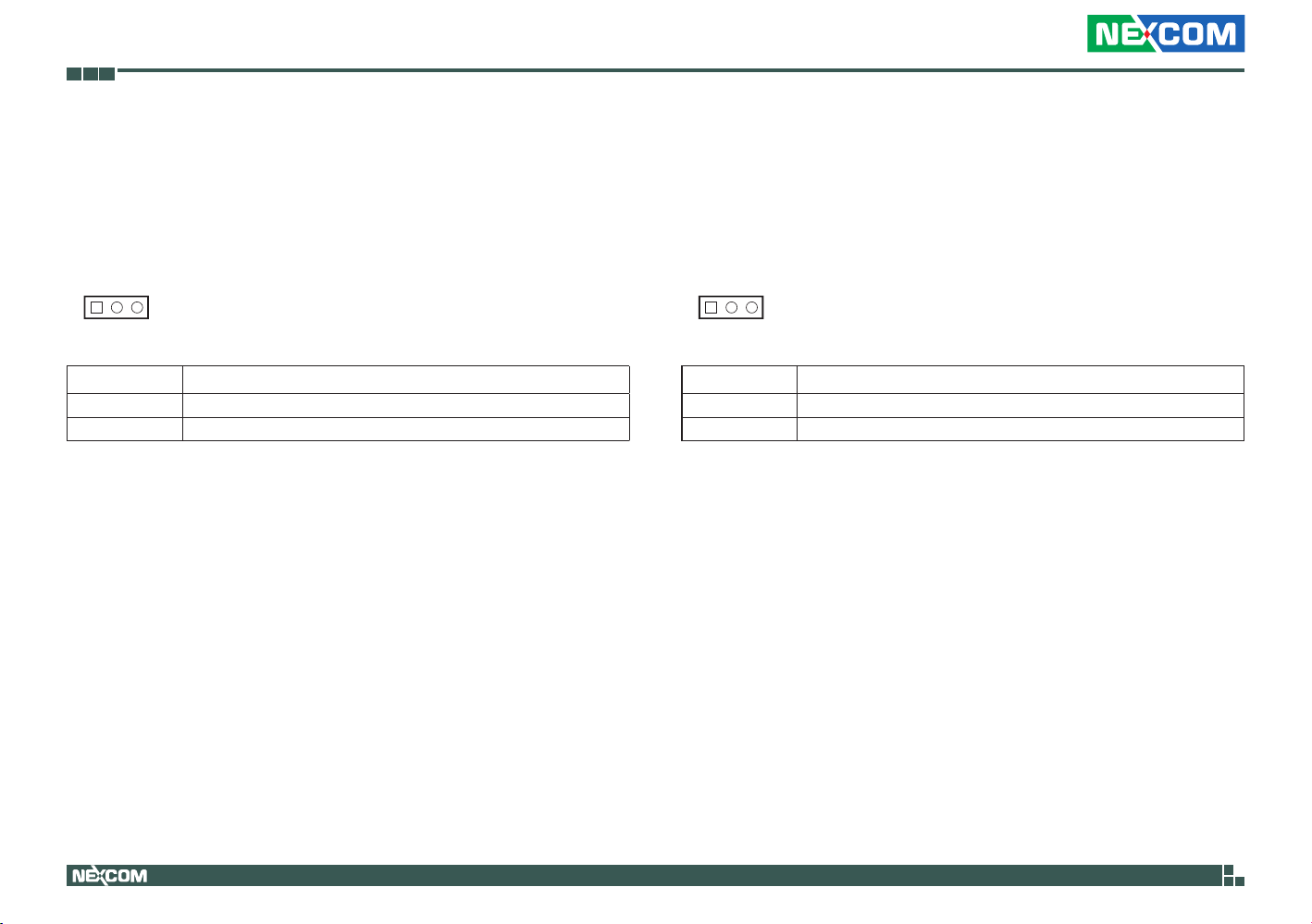
RTC Clear Pin Header
Connector type: 1x3 3-pin header, 2.54mm pitch
Connector location: JP5
1 3 1 3
Pin Settings
1-2 On Normal
2-3 On Clear BIOS
1-2 On: default
LVDS Backlight Power Select Pin Header
Connector type: 1x3 3-pin header, 2.54mm pitch
Connector location: JP12
Pin Settings
1-2 On 3.3V
2-3 On 5V
1-2 On: default
Copyright © 2013 NEXCOM International Co., Ltd. All Rights Reserved.
9
NISE 90 User Manual
Page 24
Chapter 2: Jumpers and Connectors
ACT
LINK
Connector Pin Definitions
External I/O Interfaces – Front Panel
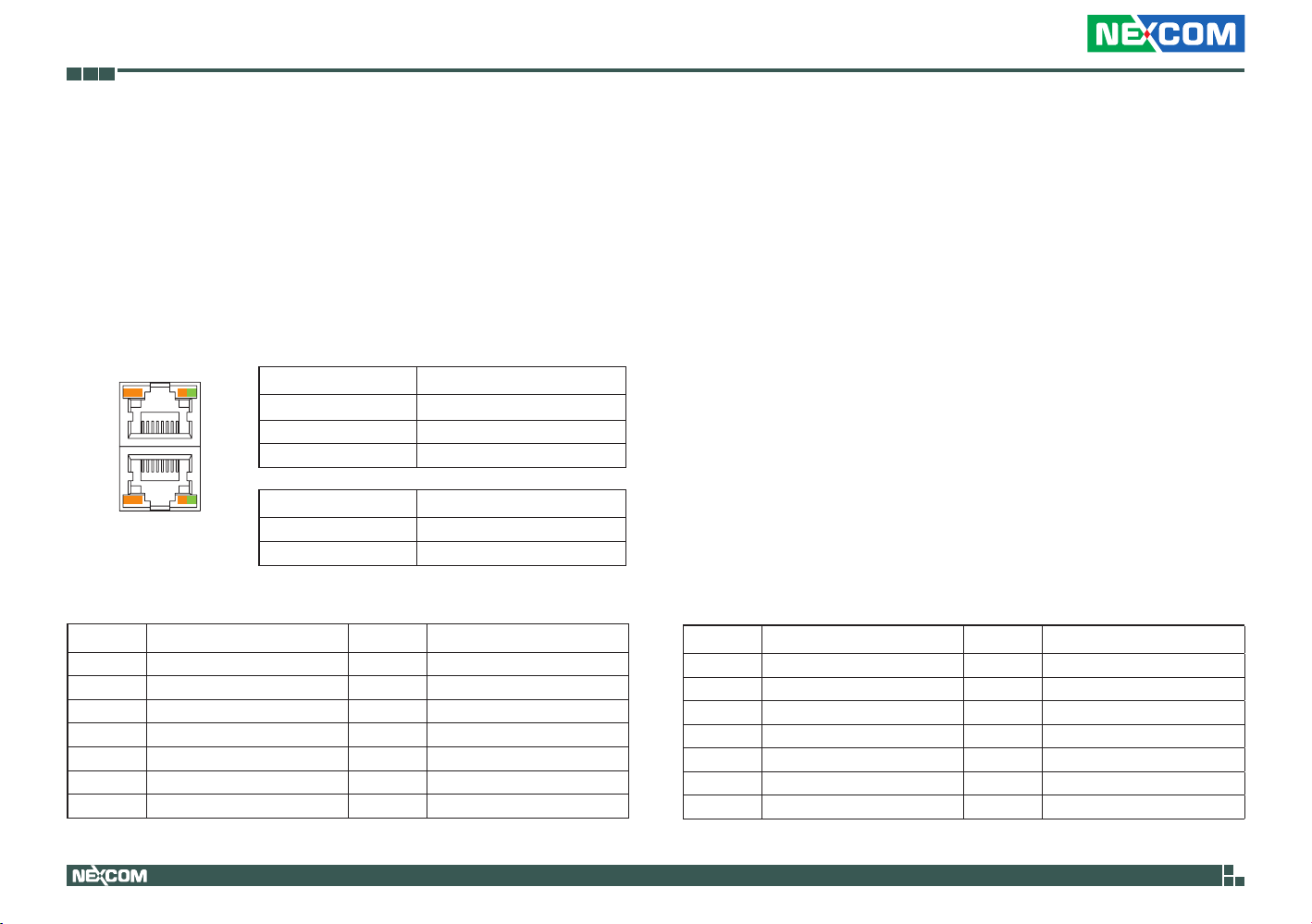
LAN1 and LAN2 Ports
Connector type: RJ45 port with LEDs
Connector location: LAN1A (LAN1) and LAN1B (LAN2)
LAN2
Link Status
B8
A1
B1
A8
Steady Orange 1G network link
Steady Green 100Mbps network link
Off 10Mbps network link
ACT
LINK
LAN1
Act Status
Flashing Orange Data activity
Off No activity
LAN1
Pin Definition Pin Definition
A1 LAN1_M0P A8 LAN1_M3N
A2 LAN1_M0N A9 VCC
A3 LAN1_M1P A10 GND
A4 LAN1_M1N A11 LAN1_ACTP
A5 LAN1_M2P A12 LAN1_LED_ACT#
A6 LAN1_M2N A13 LAN1_LINKP
A7 LAN1_M3P A14 LAN1LINKMIX
Copyright © 2013 NEXCOM International Co., Ltd. All Rights Reserved.
10
LAN2
Pin Definition Pin Definition
B1 LAN2_M0P B8 LAN2_M3N
B2 LAN2_M0N B9 VCC
B3 LAN2_M1P B10 GND
B4 LAN2_M1N B11 LAN2_ACTP
B5 LAN2_M2P B12 LAN2_LED_ACT#
B6 LAN2_M2N B13 LAN2_LINKP
B7 LAN2_M3P B14 LAN2LINKMIX
NISE 90 User Manual
Page 25
Chapter 2: Jumpers and Connectors
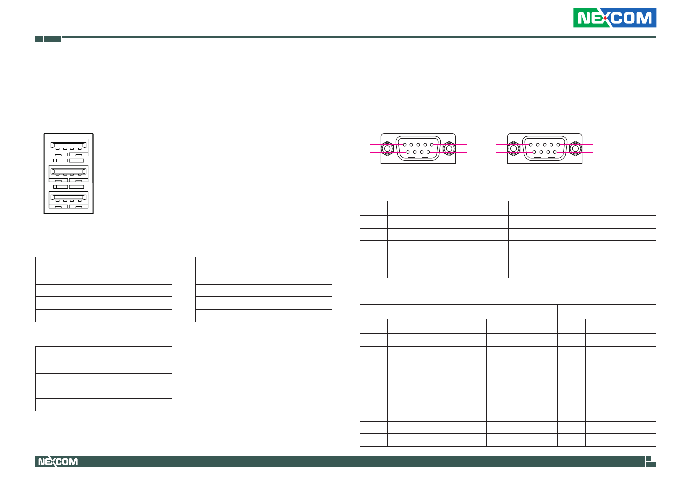
USB0, USB1 and USB2 Ports
Connector type: Triple USB 2.0 ports, Type A
Connector location: USB1
1
5
9
USB0
Pin Definition
1 +5V
2 Data 03 Data 0+
4 GND
USB2
Pin Definition
9 +5V
10 Data 211 Data 2+
12 GND
4 USB0
USB1
8
USB2
12
USB1
Pin Definition
5 +5V
6 Data 17 Data 1+
8 GND
CAN Bus and COM1 Connector
Connector type: DB-9 port
Connector location: COM1A (CAN) and COM1B (COM1)
CAN
1 5
6
10 14
9
15
CAN Bus Connector Pin Definition
Pin Definition Pin Definition
1 ISO_VCC5(OPTION) 6 ISO_GND
2 CANL 7 CANH
3 ISO_GND 8 NA
4 NA 9 ISO_VCC5(OPTION)
5 NA
COM1 Connector Pin Definition
RS232 RS485 RS422
Pin Definition Pin Definition Pin Definition
10 DCD1 10 DATA- 10 TX11 RXD1 11 DATA + 11 TX+
12 TXD1 12 NC 12 RX+
13 DTR1 13 NC 13 RX14 GND 14 GND 14 GND
15 DSR1 15 NC 15 NC
16 RTS1 16 NC 16 NC
17 CTS1 17 NC 17 NC
18 RI1 18 NC 18 NC
COM 1
18
Copyright © 2013 NEXCOM International Co., Ltd. All Rights Reserved.
11
NISE 90 User Manual
Page 26
Chapter 2: Jumpers and Connectors
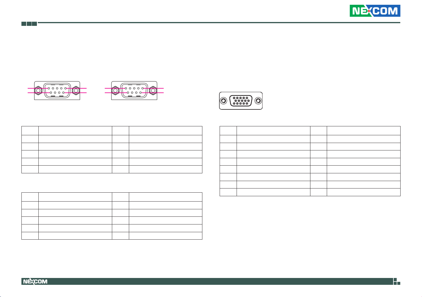
COM3 and COM2 Connector
Connector type: DB-9 port
Connector location: COM2A (COM3) and COM2B (COM2)
COM 3
1 5
6
10 14
9
15
COM 3 Connector Pin Definition
Pin Definition Pin Definition
1 DCD3 6 DSR3
2 RXD3 7 RTS3
3 TXD3 8 CTS3
4 DTR3 9 RI3
5 GND
COM 2 Connector Pin Definition
Pin Definition Pin Definition
10 DCD2 15 DSR2
11 RXD2 16 RTS2
12 TXD2 17 CTS2
13 DTR2 18 RI2
14 GND
COM 2
18
External I/O Interfaces – Rear Panel
VGA Connector
Connector type: DB-15, 15-pin D-Sub (VGA)
Connector location: VGA1
1 5
11 15
Pin Definition Pin Definition
1 Red 9 +5V
2 Green 10 GND
3 Blue 11 N/C
4 GND 12 DDC Data
5 GND 13 HSYNC
6 GND 14 VSYNC
7 GND 15 DDC Clock
8 GND
Copyright © 2013 NEXCOM International Co., Ltd. All Rights Reserved.
12
NISE 90 User Manual
Page 27
Chapter 2: Jumpers and Connectors
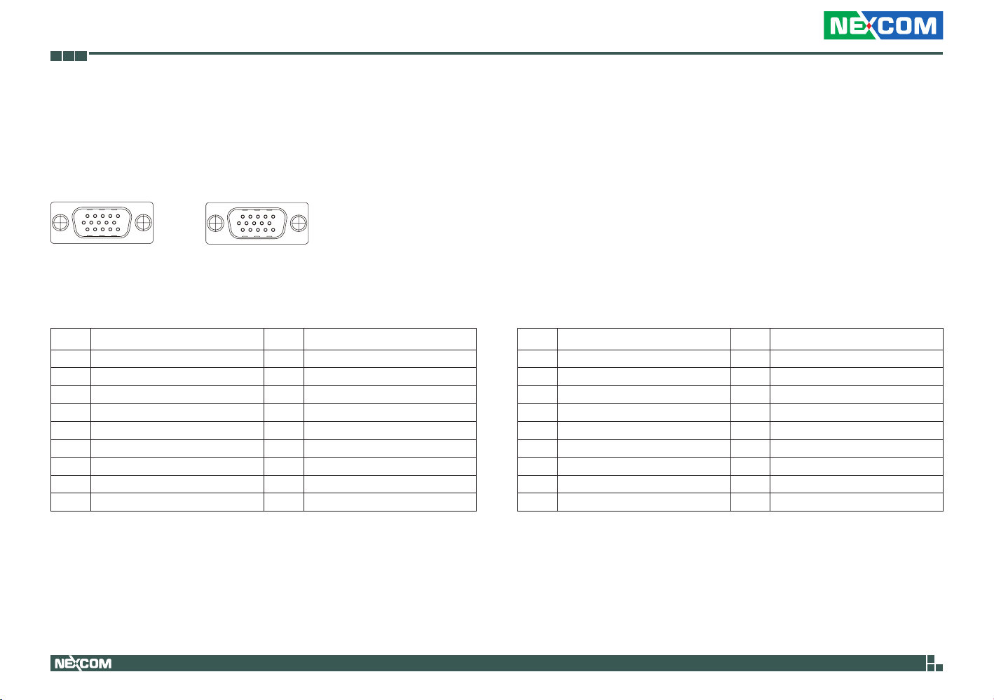
GPI & GPO Connector
Connector type: Female DB-15
Connector location: VGA2A (GPO) / VGA2B (GPI)
16
1 5
20
11
15
GPO
26
30
GPI
GPO Connector Pin Definition
Pin Definition Pin Definition
1 SIO_GPO21 10 GND
2 SIO_GPO24 11 SIO_GPO22
3 SIO_GPO27 12 SIO_GPO25
4 VCC5 13 SIO_GPO28
5 GND 14 SIO_GPO29
6 SIO_GPO20 15 NA
7 SIO_GPO23 MH1 GND
8 SIO_GPO26 MH2 GND
9 VCC5
GPI Connector Pin Definition
Pin Definition Pin Definition
16 SIO_GPI61 25 GND
17 SIO_GPI64 26 SIO_GPI62
18 SIO_GPI67 27 SIO_GPI65
19 VCC5 28 SIO_GPI68
20 GND 29 SIO_GPI69
21 SIO_GPI60 30 NA
22 SIO_GPI63 MH3 GND
23 SIO_GPI66 MH4 GND
24 VCC5
Copyright © 2013 NEXCOM International Co., Ltd. All Rights Reserved.
13
NISE 90 User Manual
Page 28
Chapter 2: Jumpers and Connectors
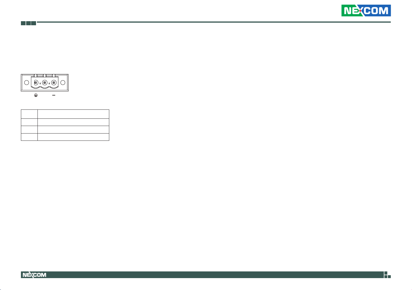
9~36V DC Power Input
Connector type: Phoenix Contact 1x3 3-pin terminal block
Connector location: CN2
+
Pin Definition
1 GND
2 +12VIN OR +24VIN
3 CH_GND
Copyright © 2013 NEXCOM International Co., Ltd. All Rights Reserved.
14
NISE 90 User Manual
Page 29
Chapter 2: Jumpers and Connectors
14
Internal Connectors
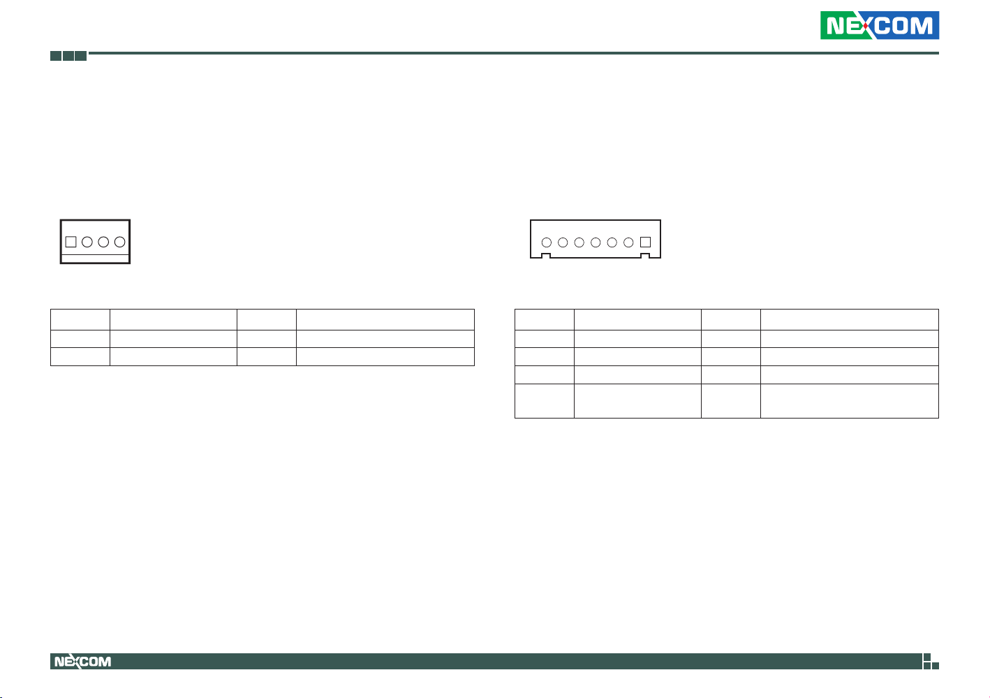
System FAN Connector
Connector type: 1x4 4-pin Wafer, 2.54mm pitch
Connector location: J1
Pin Definition Pin Definition
1 GND 3 Sense
2 +12V 4 Control
LVDS Panel Backlight Connector
Connector type: 1x7 JST, 7-pin header, 2.5mm pitch
Connector location: J6
17
Pin Definition Pin Definition
1 +5V 5 GND
2 +12V 6 GND
3 +12V 7 Panel Backlight Enable
4
Panel Backlight
Brightness Control
Copyright © 2013 NEXCOM International Co., Ltd. All Rights Reserved.
15
NISE 90 User Manual
Page 30
Chapter 2: Jumpers and Connectors
11
22
16
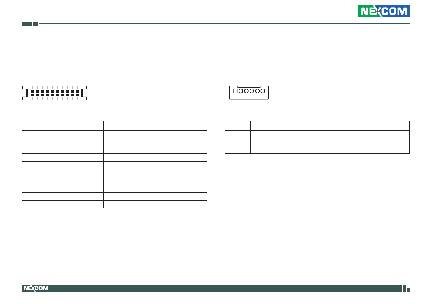
LVDS Connector
Connector type: 2x10 20-pin header, 1.25mm pitch
Connector location: CN4
9
0
Pin Definition Pin Definition
1 DDC_CLK 2 DDC_DATA
3 VCC_LCD 4 LVDS_TXP0
5 LVDS_TXP3 6 LVDS_TXN0
7 LVDS_TXN3 8 VCC_LCD
9 GND 10 LVDS_TXP1
11 LVDS_CLKP 12 LVDS_TXN1
13 LVDS_CLKN 14 GND
15 GND 16 V_INV
17 LVDS_TXP2 18 V_INV
19 LVDS_TXN2 20 GND
USB 3/4 Connector
Connector type: 1x6 JST, 6-pin header, 2.0mm pitch
Connector location: J9
Pin Definition Pin Definition
1 +5V 2 Data 33 Data 3+ 4 Data 45 Data 4+ 6 GND
Copyright © 2013 NEXCOM International Co., Ltd. All Rights Reserved.
16
NISE 90 User Manual
Page 31
Chapter 2: Jumpers and Connectors
1
13
14
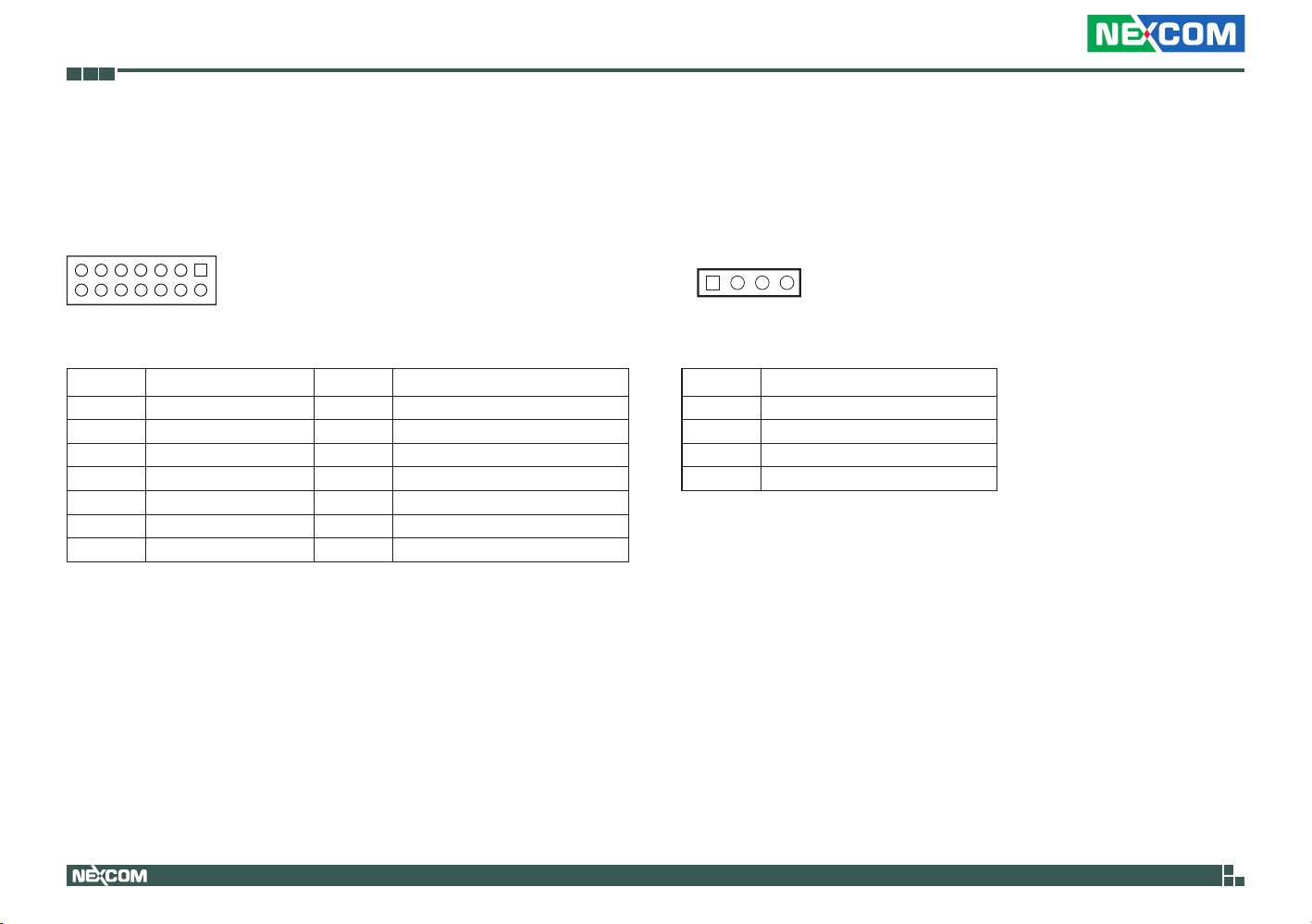
PWR_BT/RET_BT/LED/SMBUS Pin Header
Connector type: 2x7 14-pin header, 2.0mm pitch
Connector location: JP1
14
Pin Definition Pin Definition
1 PWR_LED_N 2 PWR_LED_P
3 SATA_LED# 4 SATA_LED_P
5 SMB_C 6 SMB_D
7 VCC3V3 8 GND
9 VCC3V3 10 GND
11 POWER BOTTOM 12 GND
13 RESET BOTTOM 14 GND
2
Mic-in Pin Header
Connector type: 1x4 4-pin header, 2.0mm pitch
Connector location: JP9
Pin Definition
1 MIC1_L
2 MIC_JD
3 GND
4 MIC1_R
Copyright © 2013 NEXCOM International Co., Ltd. All Rights Reserved.
17
NISE 90 User Manual
Page 32
Chapter 2: Jumpers and Connectors
14
14
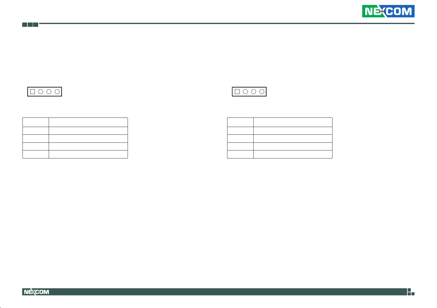
Line-in Pin Header
Connector type: 1x4 4-pin header, 2.0mm pitch
Connector location: JP13
Pin Definition
1 FLIN_L
2 LIN_JD
3 GND
4 FLIN_R
Line-out Pin Header
Connector type: 1x4 4-pin header, 2.0mm pitch
Connector location: JP10
Pin Definition
1 FLOUT_L
2 LOUT_JD
3 GND
4 FLOUT_R
Copyright © 2013 NEXCOM International Co., Ltd. All Rights Reserved.
18
NISE 90 User Manual
Page 33
Chapter 2: Jumpers and Connectors
12
34
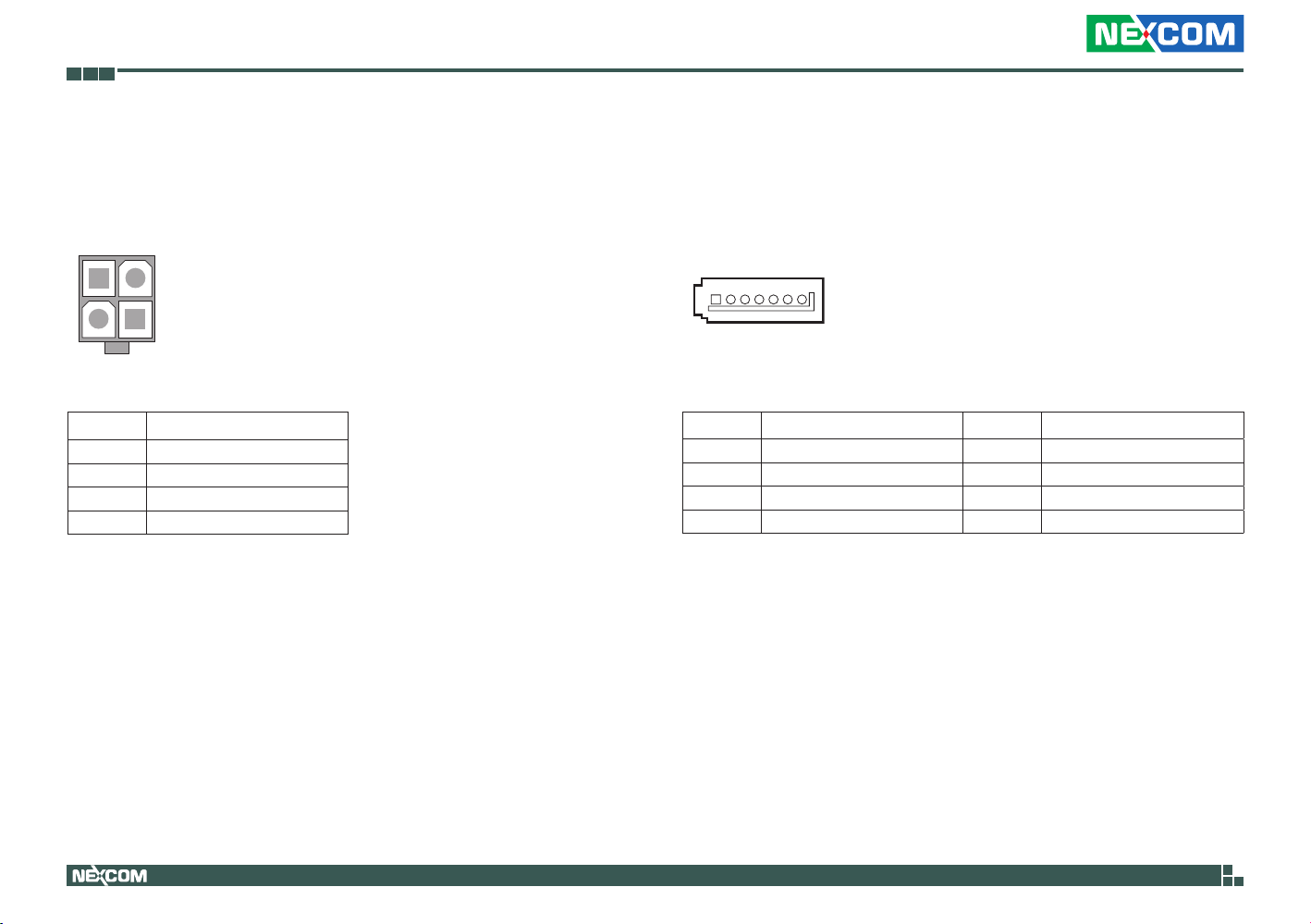
PoE Power Connector
Connector type: 2x2 4-pin header, 3.5mm pitch
Connector location: CN1
Pin Definition
1 GND
2 GND
3 VIN Power
4 VIN Power
SATA0 Connector
Connector type: Standard Serial ATAII 7P (1.27mm, SATA-M-180)
Connector location: J5
1 7
Pin Definition Pin Definition
1 GND 5 SATA_RXN1
2 SATA_TXP1 6 SATA_RXP1
3 SATA_TXN1 7 GND
4 GND
Copyright © 2013 NEXCOM International Co., Ltd. All Rights Reserved.
19
NISE 90 User Manual
Page 34
Chapter 2: Jumpers and Connectors
14
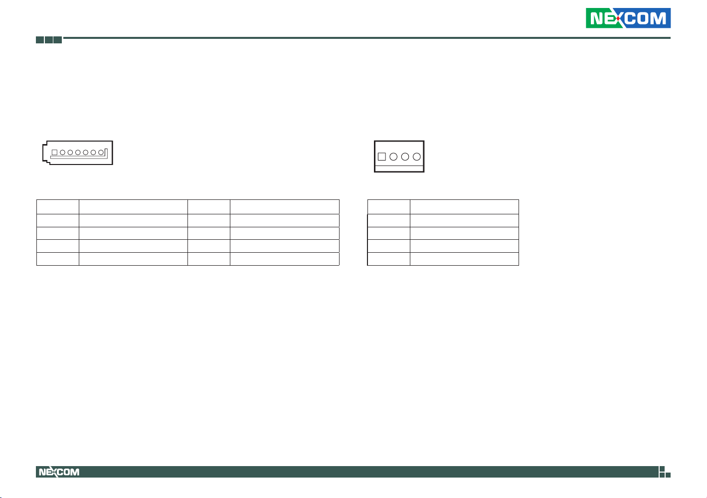
SATA1 Connector
Connector type: Standard Serial ATAII 7P (1.27mm, SATA-M-180)
Connector location: J4
1 7
Pin Definition Pin Definition
1 GND 5 SATA_RXN0
2 SATA_TXP0 6 SATA_RXP0
3 SATA_TXN0 7 GND
4 GND
SATA Power Connector
Connector type: 1x4 4-pin header, 2.54mm pitch
Connector location: CN5
Pin Definition
1 +12V
2 GND
3 GND
4 VCC5
Copyright © 2013 NEXCOM International Co., Ltd. All Rights Reserved.
20
NISE 90 User Manual
Page 35
Chapter 2: Jumpers and Connectors
17
28
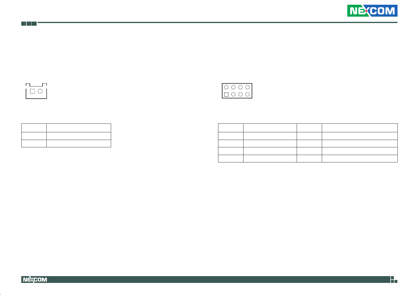
SATA-DOM Power Connector
Connector type: 1x2 2-pin header, 2.5mm pitch
Connector location: J8
1 2
Pin Definition
1 VCC5
2 GND
Keyboard / Mouse Pin Header
Connector type: 2x4 8-pin header, 2.54mm pitch
Connector location: J2
Pin Definition Pin Definition
1 KBMSVCC 5 LKBCLK
2 KBMSVCC 6 LMCLK
3 LKBDAT 7 GND
4 LMDAT 8 GND
Copyright © 2013 NEXCOM International Co., Ltd. All Rights Reserved.
21
NISE 90 User Manual
Page 36
Chapter 2: Jumpers and Connectors
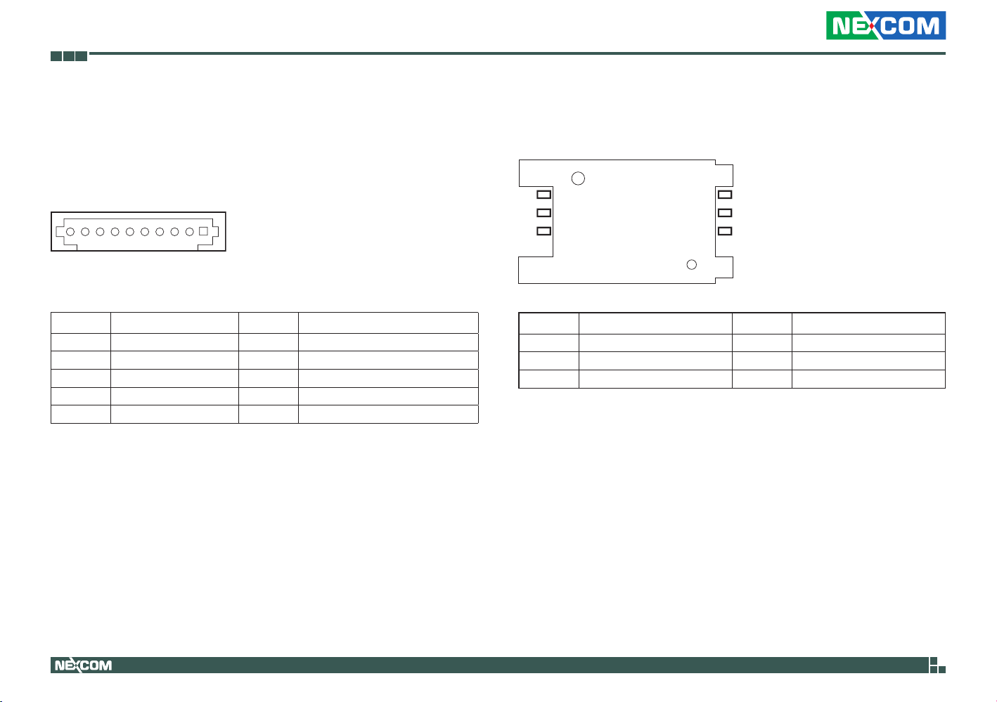
10 1
COM4 Box Pin Header
Connector type: 1x10 10-pin header, 1.0mm pitch
Connector location: J16
Pin Definition Pin Definition
1 SIO_DCD#4 2 SIO_RXD4
3 SIO_TXD4 4 SIO_DTR#4
5 GND 6 SIO_DSR#4
7 SIO_RTS#4 8 SIO_CTS#4
9 SIO_RI#4 10 GND
SIM Card Connector
Connector location: IDE1
C3
C2
C1
Pin Definition Pin Definition
C1 UIM_PWR C2 UIM_RESET
C3 UIM_CLK C5 GND
C6 UIM_VPP C7 UIM_DATA
C7
C6
C5
Copyright © 2013 NEXCOM International Co., Ltd. All Rights Reserved.
22
NISE 90 User Manual
Page 37
Chapter 2: Jumpers and Connectors
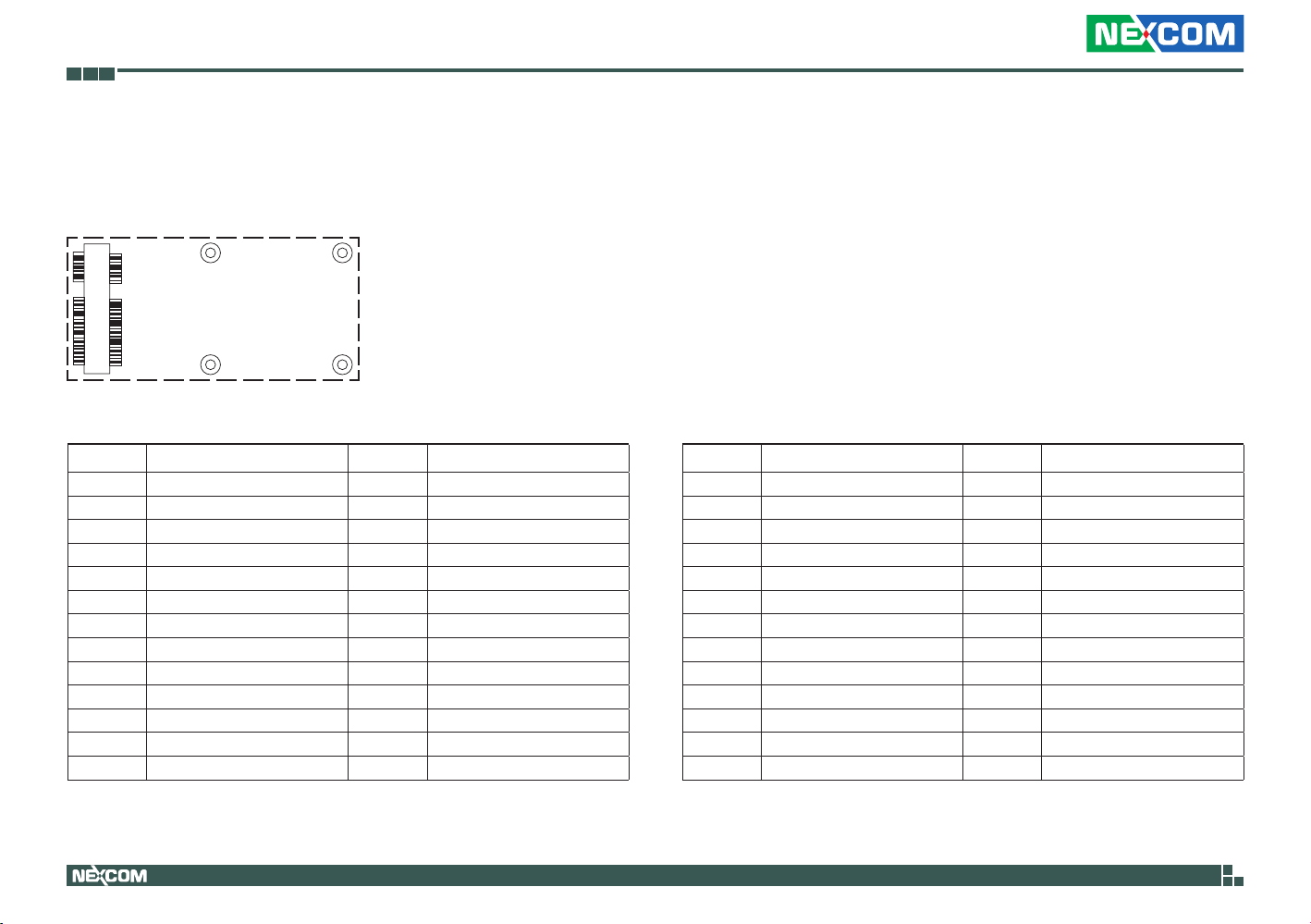
Mini-PCIe Connector
Connector location: CN3
12
51 52
Pin Definition Pin Definition
1 WAKE# 14 UIM_RESET
2 +3VSB 15 GND
3 COEX1 16 UIM_VPP
4 GND 17 N/A
5 COEX2 18 GND
6 +1.5V 19 N/A
7 CLKREQ# 20 Disable#
8 UIM_PWR 21 GND
9 GND 22 PERST#
10 UIM_DATA 23 PCIERX11 REF CLK- 24 +3VSB
12 UIM_CLK 25 PCIERX+
13 REF CLK+ 26 GND
Copyright © 2013 NEXCOM International Co., Ltd. All Rights Reserved.
23
Pin Definition Pin Definition
27 GND 40 GND
28 +1.5V 41 +3VSB
29 GND 42 N/A
30 SMBCLK 43 GND
31 PCIETX- 44 N/A
32 SMBDATA 45 N/A
33 PCIETX+ 46 N/A
34 GND 47 N/A
35 GND 48 +1.5V
36 USB_D- 49 N/A
37 GND 50 GND
38 USB_D+ 51 N/A
39 +3VSB 52 +3VSB
NISE 90 User Manual
Page 38
Chapter 3: System Setup
CAUTION!
Chapter 3: System Setup
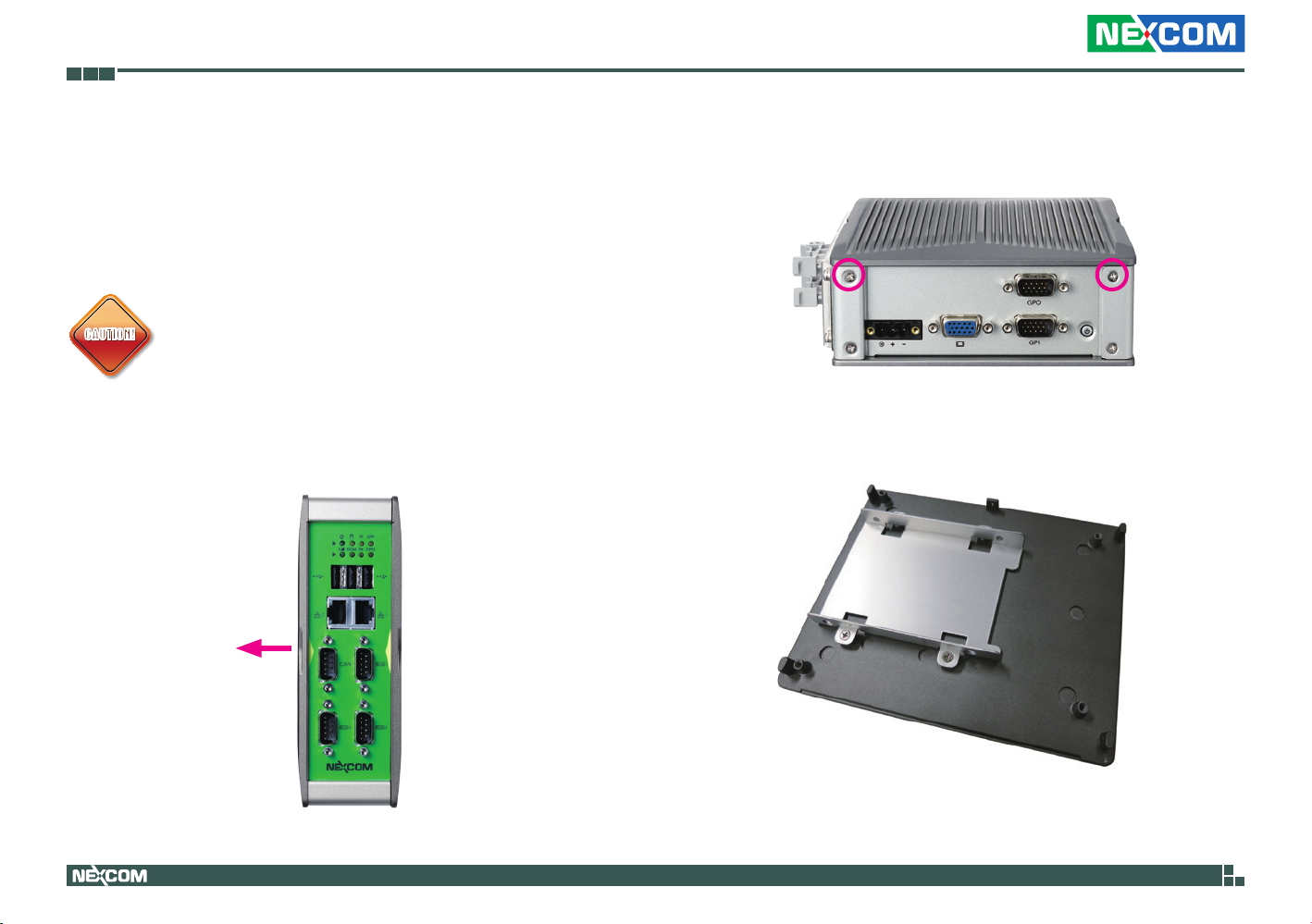
Removing the Chassis Cover
CAUTION!CAUTION!
1. Remove the mounting screw on the left side of the system and put them in
a safe place for later use.
Prior to removing the chassis cover, make sure the unit’s power
is off and disconnected from the power sources to prevent
electric shock or system damage.
Remove screws
around this side
of system
2. Lift up the cover and remove it from the chassis.
Copyright © 2013 NEXCOM International Co., Ltd. All Rights Reserved.
24
NISE 90 User Manual
Page 39
Chapter 3: System Setup
Installing a SATA Hard Drive
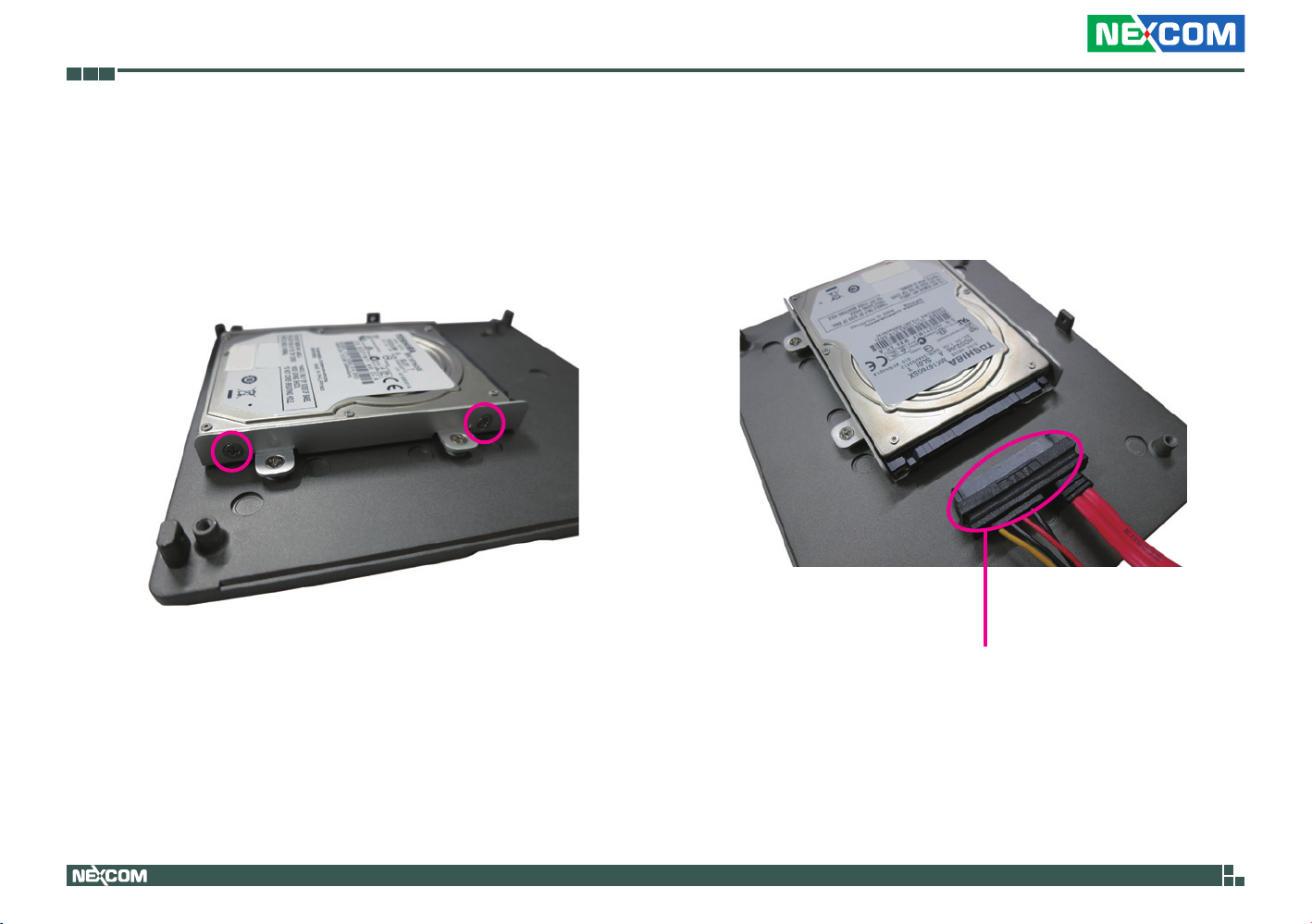
1. With the top cover removed, place the SATA drive in the hard drive
bracket with the mounting holes aligned. Then use the provided screws
to secure the drive in place
2. Connect the SATA data/power cable to the connector on the hard drive.
SATA data/power cable
Copyright © 2013 NEXCOM International Co., Ltd. All Rights Reserved.
25
NISE 90 User Manual
Page 40
Chapter 3: System Setup
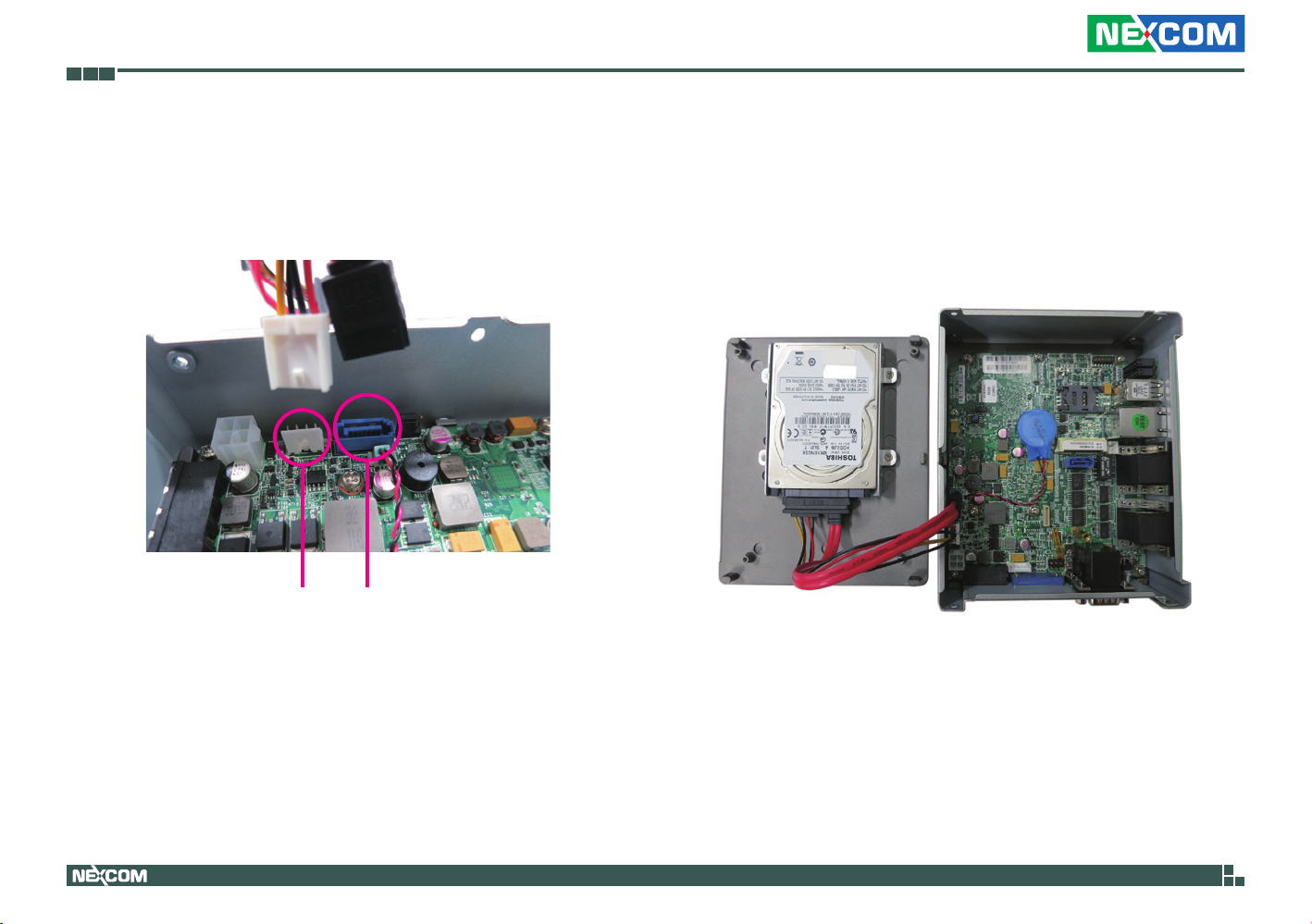
3. Connect the other side of SATA data/power cable to the PCBA.
4. Secure the cover to its original position.
SATA power cable SATA cable
Copyright © 2013 NEXCOM International Co., Ltd. All Rights Reserved.
26
NISE 90 User Manual
Page 41
Chapter 3: System Setup
Installing a Wireless LAN Module
(half-size)
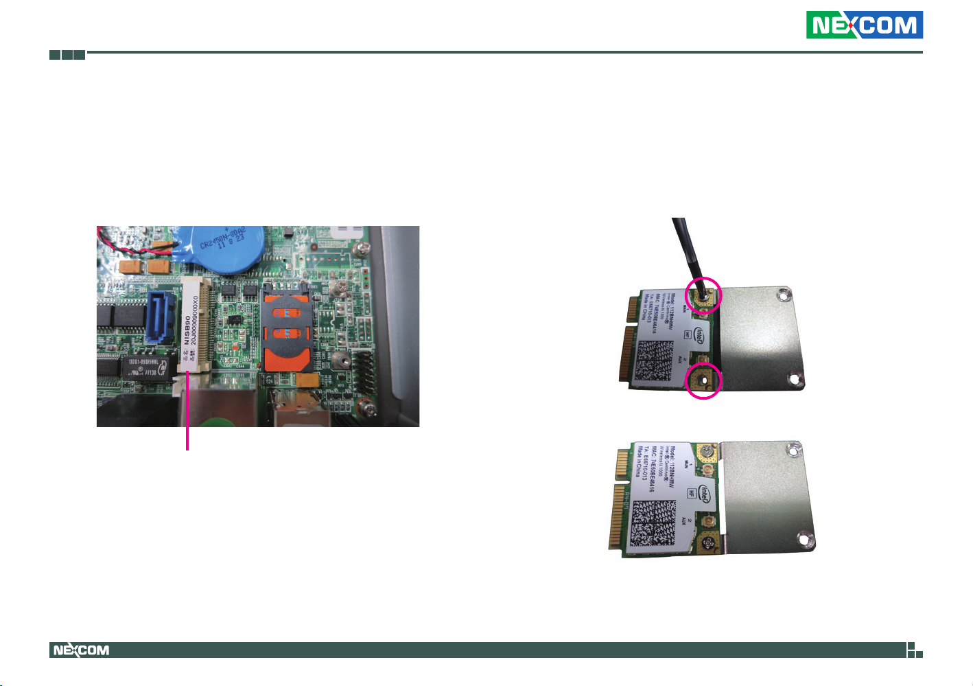
1. Locate the Mini PCI Express slot on the board.
Mini PCI Express Slot
2. Fasten the wireless LAN module to the mini PCI express bracket.
Copyright © 2013 NEXCOM International Co., Ltd. All Rights Reserved.
27
NISE 90 User Manual
Page 42
Chapter 3: System Setup
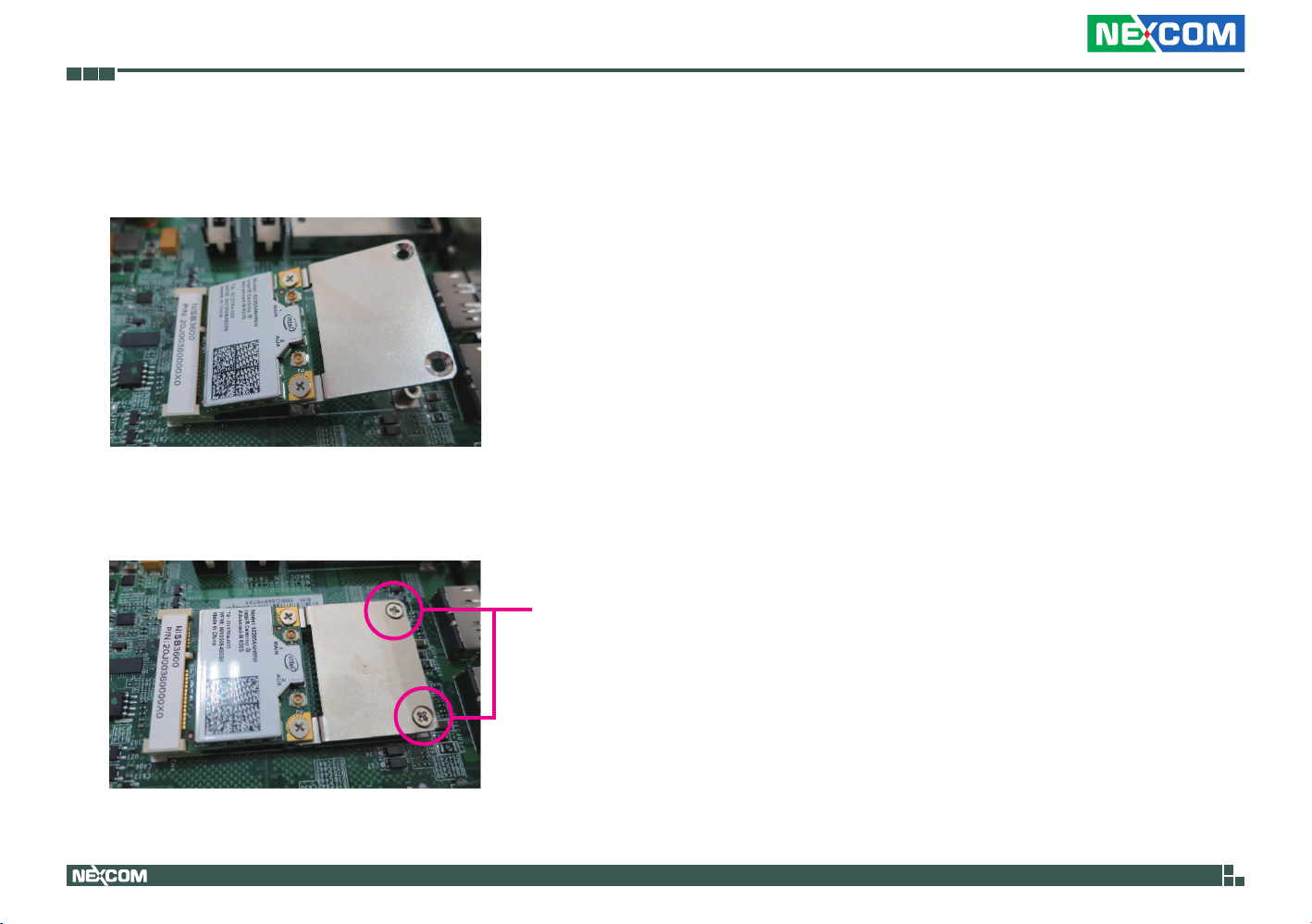
3. Insert the Wi-Fi module into the Mini PCI Express slot at a 45 degree
angle until the gold-plated connector on the edge of the module
completely disappears inside the slot.
4. Push the module down and then secure it with mounting screws.
Copyright © 2013 NEXCOM International Co., Ltd. All Rights Reserved.
Screw
28
NISE 90 User Manual
Page 43
Chapter 3: System Setup
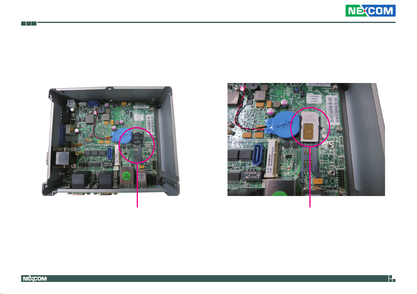
Installing a SIM Card
1. Locate the SIM card socket on the PCBA, then lift up the socket cover.
SIM card bracket
2. Slide the SIM card into the slot with the golden contacts facing inwards.
SIM card
Copyright © 2013 NEXCOM International Co., Ltd. All Rights Reserved.
29
NISE 90 User Manual
Page 44
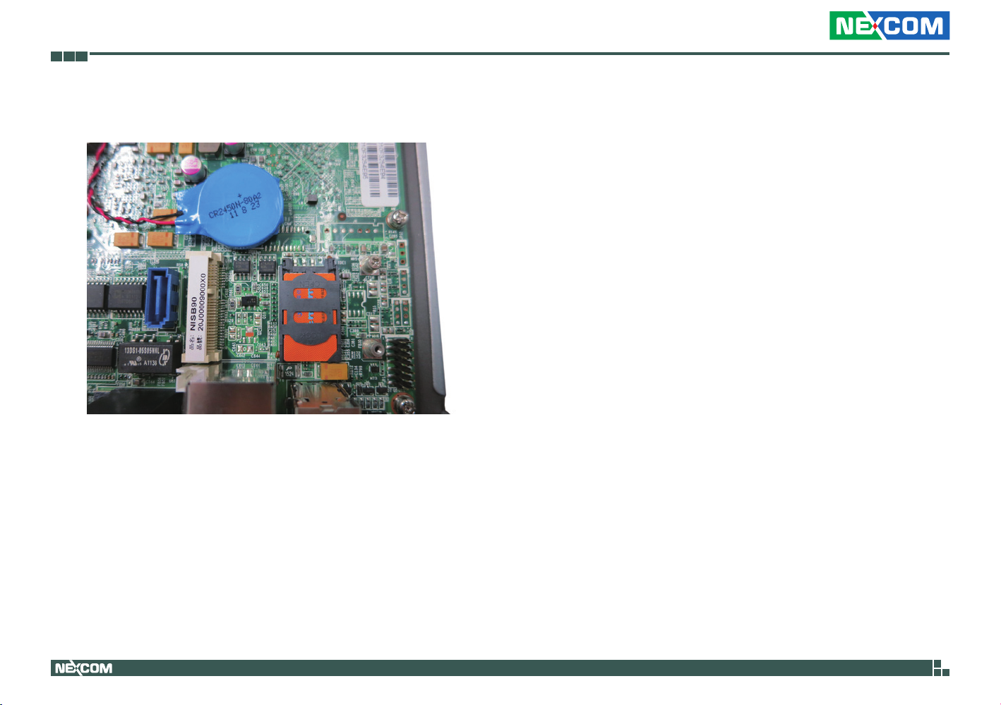
Chapter 3: System Setup
3. Push the socket cover back to its original position.
Copyright © 2013 NEXCOM International Co., Ltd. All Rights Reserved.
30
NISE 90 User Manual
Page 45

Chapter 4: BIOS Setup
Chapter 4: BIOS Setup
This chapter describes how to use the BIOS setup program for the NISE 90. The
BIOS screens provided in this chapter are for reference only and may change if
the BIOS is updated in the future.
To check for the latest updates and revisions, visit the NEXCOM Web site at
www.nexcom.com.tw.
About BIOS Setup
The BIOS (Basic Input and Output System) Setup program is a menu driven
utility that enables you to make changes to the system configuration and
tailor your system to suit your individual work needs. It is a ROM-based
configuration utility that displays the system’s configuration status and
provides you with a tool to set system parameters.
These parameters are stored in non-volatile battery-backed-up CMOS RAM that
saves this information even when the power is turned off. When the system is
turned back on, the system is configured with the values found in CMOS.
With easy-to-use pull down menus, you can configure such items as:
▪ Hard drives, diskette drives, and peripherals
▪ Video display type and display options
▪ Password protection from unauthorized use
▪ Power management features
The settings made in the setup program affect how the computer performs.
It is important, therefore, first to try to understand all the setup options, and
second, to make settings appropriate for the way you use the computer.
When to Configure the BIOS
▪ This program should be executed under the following conditions:
▪ When changing the system configuration
▪ When a configuration error is detected by the system and you are
prompted to make changes to the setup program
▪ When resetting the system clock
▪ When redefining the communication ports to prevent any conflicts
▪ When making changes to the Power Management configuration
▪ When changing the password or making other changes to the security
setup
Normally, CMOS setup is needed when the system hardware is not consistent
with the information contained in the CMOS RAM, whenever the CMOS
RAM has lost power, or the system features need to be changed.
Copyright © 2013 NEXCOM International Co., Ltd. All Rights Reserved.
31
NISE 90 User Manual
Page 46
Chapter 4: BIOS Setup
Default Configuration
Most of the configuration settings are either predefined according to
the Load Optimal Defaults settings which are stored in the BIOS or are
automatically detected and configured without requiring any actions. There
are a few settings that you may need to change depending on your system
configuration.
Entering Setup
When the system is powered on, the BIOS will enter the Power-On Self
Test (POST) routines. These routines perform various diagnostic checks; if an
error is encountered, the error will be reported in one of two different ways:
▪ If the error occurs before the display device is initialized, a series of beeps
will be transmitted.
▪ If the error occurs after the display device is initialized, the screen will
display the error message.
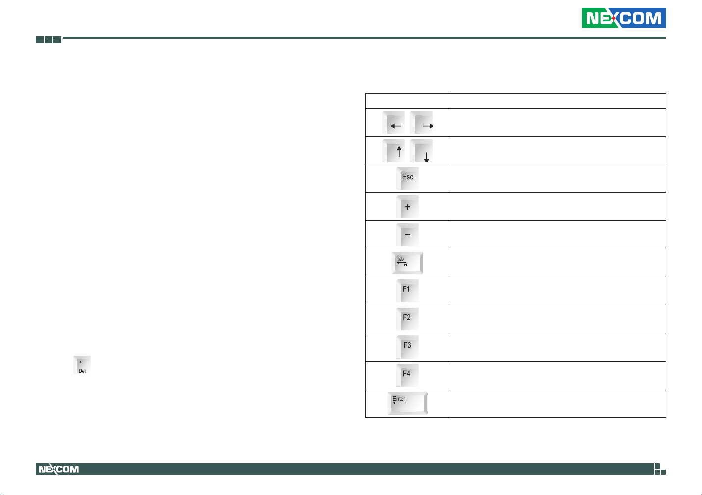
Powering on the computer and immediately pressing <Del> allows you to
enter Setup.
Legends
Key Function
Moves the highlight left or right to select a menu.
Moves the highlight up or down between
sub¬menus or fields.
Exits the BIOS Setup Utility.
Scrolls forward through the values or options of the
highlighted field.
Scrolls backward through the values or options of
the highlighted field.
Selects a field.
Displays General Help.
Load previous values.
Load optimized default values.
Press the
Copyright © 2013 NEXCOM International Co., Ltd. All Rights Reserved.
key to enter Setup:
32
Saves and exits the Setup program.
Press <Enter> to enter the highlighted sub¬menu
NISE 90 User Manual
Page 47
Chapter 4: BIOS Setup
Scroll Bar
When a scroll bar appears to the right of the setup screen, it indicates that
there are more available fields not shown on the screen. Use the up and
down arrow keys to scroll through all the available fields.
Submenu
When “” appears on the left of a particular field, it indicates that a
submenu which contains additional options are available for that field. To
display the submenu, move the highlight to that field and press .
Copyright © 2013 NEXCOM International Co., Ltd. All Rights Reserved.
33
NISE 90 User Manual
Page 48
Chapter 4: BIOS Setup
BIOS Setup Utility
Once you enter the AMI BIOS Setup Utility, the Main Menu will appear on
the screen. The main menu allows you to select from several setup functions
and one exit. Use arrow keys to select among the items and press to
accept or enter the submenu.
Main
The Main menu is the first screen that you will see when you enter the BIOS
Setup Utility.
Aptio Setup Utility - Copyright (C) 2010 American Megatrends, Inc.
BIOS Information
BIOS Vendor
Core Version
Project Version
Build Date and Time
Memory Information
MRC Version
Total Memory
Platform Information
►
System Date
System Time
Access Level
Advanced Chipset Boot SecurityMain
American Megatrends
4.6.3.7
N090-006
12/19/2011 16:46:15
00.90
512 MB (DDR2)
[Thu 07/04/2013]
[07:01:23]
Administrator
Version 2.10.1208. Copyright (C) 2010 American Megatrends, Inc.
Save & Exit
Platform Information
→←: Select Screen
↑↓: Select Item
Enter: Select
+/-: Change Opt.
F1: General Help
F2: Previous Values
F3: Optimized Defaults
F4: Save & Exit
ESC: Exit
Platform Information
Displays the platform information.
Aptio Setup Utility - Copyright (C) 2010 American Megatrends, Inc.
Advanced Chipset Boot SecurityMain
Platform Information
Tunnel Creek Version
IGD VBIOS Version
PUNIT Build Date
PUNIT Build Time
Version 2.10.1208. Copyright (C) 2010 American Megatrends, Inc.
02
2032
May 24 2011
0:38:19
Save & Exit
→←: Select Screen
↑↓: Select Item
Enter: Select
+/-: Change Opt.
F1: General Help
F2: Previous Values
F3: Optimized Defaults
F4: Save & Exit
ESC: Exit
System Date
The date format is <day>, <month>, <date>, <year>. Day displays a day, from
Monday to Sunday. Month displays the month, from January to December.
Date displays the date, from 1 to 31. Year displays the year, from 1999 to 2099.
System Time
The time format is <hour>, <minute>, <second>. The time is based on the
24-hour military-time clock. For example, 1 p.m. is 13:00:00. Hour displays
hours from 00 to 23. Minute displays minutes from 00 to 59. Second displays
seconds from 00 to 59.
Access Level
Displays the access level of the current user in the BIOS.
Copyright © 2013 NEXCOM International Co., Ltd. All Rights Reserved.
34
NISE 90 User Manual
Page 49
Chapter 4: BIOS Setup
Advanced
The Advanced menu allows you to configure your system for basic operation.
Some entries are defaults required by the system board, while others, if
enabled, will improve the performance of your system or let you set some
features according to your preference.
Setting incorrect field values may cause the system to
malfunction.
Aptio Setup Utility - Copyright (C) 2010 American Megatrends, Inc.
Advanced Chipset Boot SecurityMain
Legacy OpROM Support
Launch PXE OpROM
CPU Conguration
Sdio Conguration
USB Conguration
Super IO Conguration
H/W Monitor
[Disabled]
Launch Lan1 PXE OpROM
Disabled
Enabled
Save & Exit
Enable or Disable Boot Option
for Lan1
→←: Select Screen
↑↓: Select Item
Enter: Select
+/-: Change Opt.
F1: General Help
F2: Previous Values
F3: Optimized Defaults
F4: Save & Exit
ESC: Exit
CPU Configuration
This section is used to configure the CPU settings.
Aptio Setup Utility - Copyright (C) 2010 American Megatrends, Inc.
Advanced
CPU Conguration
Processor Type
EMT64
Processor Speed
System Bus Speed
Ratio Status
Actual Ratio
Processor Stepping
Microcode Revision
L1 Cache RAM
L2 Cache RAM
Processor Core
Hyper-Threading
Intel SpeedStep
Hyper-Threading
Execute Disable Bit
Limit CPUID Maximum
Intel Virtualization Technology
C-States
Enhanced C1
Enhanced C2
Enhanced C3
Enhanced C4
Version 2.10.1208. Copyright (C) 2010 American Megatrends, Inc.
Genuine Intel(R) CPU
Supported
600 MHz
400 MHZ
6
6
20661
260
56 k
512 k
Single
Supported
[Enabled]
[Enabled]
[Enabled]
[Disabled]
[Disabled]
[Enabled]
[Disabled]
[Enabled]
[Disabled]
[Enabled]
Enable or Disable Intel(R)
SpeedStep(tm)
→←: Select Screen
↑↓: Select Item
Enter: Select
+/-: Change Opt.
F1: General Help
F2: Previous Values
F3: Optimized Defaults
F4: Save & Exit
ESC: Exit
Version 2.10.1208. Copyright (C) 2010 American Megatrends, Inc.
Launch PXE OpROM
Enables or disables the boot option for legacy network devices connected
to LAN1.
Copyright © 2013 NEXCOM International Co., Ltd. All Rights Reserved.
35
NISE 90 User Manual
Page 50
Chapter 4: BIOS Setup
Intel® SpeedStep
Aptio Setup Utility - Copyright (C) 2010 American Megatrends, Inc.
Advanced
CPU Conguration
Processor Type
EMT64
Processor Speed
System Bus Speed
Ratio Status
Actual Ratio
Processor Stepping
Microcode Revision
L1 Cache RAM
L2 Cache RAM
Processor Core
Hyper-Threading
Intel SpeedStep
Hyper-Threading
Execute Disable Bit
Limit CPUID Maximum
Intel Virtualization Technology
C-States
Enhanced C1
Enhanced C2
Enhanced C3
Enhanced C4
Genuine Intel(R) CPU
Supported
600 MHz
400 MHZ
6
6
20661
260
56 k
Intel SpeedStep
512 k
Disabled
Single
Enabled
Supported
[Enabled]
[Enabled]
[Enabled]
[Disabled]
[Disabled]
[Enabled]
[Disabled]
[Enabled]
[Disabled]
[Enabled]
Enable or Disable Intel(R)
SpeedStep(tm)
→←: Select Screen
↑↓: Select Item
Enter: Select
+/-: Change Opt.
F1: General Help
F2: Previous Values
F3: Optimized Defaults
F4: Save & Exit
ESC: Exit
Version 2.10.1208. Copyright (C) 2010 American Megatrends, Inc.
This field is used to enable or disable Intel® SpeedStep™
Hyper-Threading
Aptio Setup Utility - Copyright (C) 2010 American Megatrends, Inc.
Advanced
CPU Conguration
Processor Type
EMT64
Processor Speed
System Bus Speed
Ratio Status
Actual Ratio
Processor Stepping
Microcode Revision
L1 Cache RAM
L2 Cache RAM
Processor Core
Hyper-Threading
Intel SpeedStep
Hyper-Threading
Execute Disable Bit
Limit CPUID Maximum
Intel Virtualization Technology
C-States
Enhanced C1
Enhanced C2
Enhanced C3
Enhanced C4
Genuine Intel(R) CPU
Supported
600 MHz
400 MHZ
6
6
20661
260
56 k
Hyper-Threading
512 k
Disabled
Single
Enabled
Supported
[Enabled]
[Enabled]
[Enabled]
[Disabled]
[Disabled]
[Enabled]
[Disabled]
[Enabled]
[Disabled]
[Enabled]
Enabled for Windows XP and
Linux (OS optimized for HyperThreading Technology) and
Disabled for other OS (OS not
optimized for Hyper-Threading
Technology).
→←: Select Screen
↑↓: Select Item
Enter: Select
+/-: Change Opt.
F1: General Help
F2: Previous Values
F3: Optimized Defaults
F4: Save & Exit
ESC: Exit
Version 2.10.1208. Copyright (C) 2010 American Megatrends, Inc.
This field is used to enable or disable hyper-threading.
Copyright © 2013 NEXCOM International Co., Ltd. All Rights Reserved.
36
NISE 90 User Manual
Page 51
Chapter 4: BIOS Setup
Execute Disable Bit
When this field is set to Disabled, it will force the XD feature flag to always
return to 0. XD can prevent certain classes of malicious buffer overflow
attacks when combined with a supporting OS (Windows Server 2003 SP1,
Windows XP SP2, SuSE Linux 9.2, RedHat Enterprise 3 Update 3).
Limit CPUID Maximum
The CPUID instruction of some newer CPUs will return a value greater
than 3. The default is Disabled because this problem does not exist in the
Windows series operating systems. If you are using an operating system
other than Windows, this problem may occur. To avoid this problem,
enable this field to limit the return value to 3 or lesser than 3.
Intel® Virtualization Technology
When enabled, a VMM can utilize the additional hardware capabilities
provided by vanderpool technology.
C-States
Aptio Setup Utility - Copyright (C) 2010 American Megatrends, Inc.
Advanced
CPU Conguration
Processor Type
EMT64
Processor Speed
System Bus Speed
Ratio Status
Actual Ratio
Processor Stepping
Microcode Revision
L1 Cache RAM
L2 Cache RAM
Processor Core
Hyper-Threading
Intel SpeedStep
Hyper-Threading
Execute Disable Bit
Limit CPUID Maximum
Intel Virtualization Technology
C-States
Enhanced C1
Enhanced C2
Enhanced C3
Enhanced C4
Version 2.10.1208. Copyright (C) 2010 American Megatrends, Inc.
Genuine Intel(R) CPU
Supported
600 MHz
400 MHZ
6
6
20661
260
56 k
C-States
512 k
Disabled
Single
Enabled
Supported
[Enabled]
[Enabled]
[Enabled]
[Disabled]
[Disabled]
[Enabled]
[Disabled]
[Enabled]
[Disabled]
[Enabled]
C-States
Enables or disables C2 and above.
Enhanced C1
Enables or disables Enhanced C1 state.
Enable or Disable C2 and above
→←: Select Screen
↑↓: Select Item
Enter: Select
+/-: Change Opt.
F1: General Help
F2: Previous Values
F3: Optimized Defaults
F4: Save & Exit
ESC: Exit
Copyright © 2013 NEXCOM International Co., Ltd. All Rights Reserved.
Enhanced C2
Enables or disables Enhanced C2 state.
Enhanced C3
Enables or disables Enhanced C3 state.
Enhanced C4
Enables or disables Enhanced C4 state.
37
NISE 90 User Manual
Page 52
Chapter 4: BIOS Setup
Sdio Configuration
This section is used to configure the SDIO access mode.
Aptio Setup Utility - Copyright (C) 2010 American Megatrends, Inc.
Advanced
▲
Sdio Conguration
SDIO Access Mode
Version 2.10.1208. Copyright (C) 2010 American Megatrends, Inc.
[Auto]
SDIO Access Mode
Auto
DMA
PIO
Auto Option: Access SD device in
DMA mode if controller support
it, otherwise in PIO mode. DAM
Option: Access SD device in DMA
mode. PIO Option: Access SD
device in PIO.
→←: Select Screen
↑↓: Select Item
Enter: Select
+/-: Change Opt.
F1: General Help
F2: Previous Values
F3: Optimized Defaults
F4: Save & Exit
ESC: Exit
▲
Sdio Configuration
Auto Option Access SD device in DMA mode if controller support it,
otherwise in PIO mode.
DAM Option Access SD device in DMA mode.
PIO Option Access SD device in PIO mode.
USB Configuration
This section is used to configure the USB.
Aptio Setup Utility - Copyright (C) 2010 American Megatrends, Inc.
Advanced
USB Conguration
USB Devices:
1 Keyboard
Legacy USB Support
EHCI Hand-off
Device Reset timeout
Version 2.10.1208. Copyright (C) 2010 American Megatrends, Inc.
[Enabled]
[Enabled]
[20 sec]
Enables Legacy USB support.
AUTO option disables legacy
support if no USB devices are
connected. DISABLE option will
keep USB devices available
only for EFI applications.
→←: Select Screen
↑↓: Select Item
Enter: Select
+/-: Change Opt.
F1: General Help
F2: Previous Values
F3: Optimized Defaults
F4: Save & Exit
ESC: Exit
Legacy USB Support
Enable Enables Legacy USB.
Auto Disables support for Legacy when no USB devices are connected.
Disable Keeps USB devices available only for EFI applications.
EHCI Hand-off
This is a workaround for OSes that does not support EHCI hand-off. The
EHCI ownership change should be claimed by the EHCI driver.
Copyright © 2013 NEXCOM International Co., Ltd. All Rights Reserved.
Device Reset Timeout
USB mass storage device start unit command timeout.
38
NISE 90 User Manual
Page 53
Chapter 4: BIOS Setup
Super IO Configuration
This section is used to configure the serial ports.
Aptio Setup Utility - Copyright (C) 2010 American Megatrends, Inc.
Advanced
Super IO Conguration
Super IO Chip
Serial Port 0 Conguration
Serial Port 1 Conguration
Serial Port 2 Conguration
Serial Port 3 Conguration
IT8783F
Version 2.10.1208. Copyright (C) 2010 American Megatrends, Inc.
Super IO Chip
Displays the Super I/O chip used on the board.
Set Parameters of Serial Port
O (COMA)
→←: Select Screen
↑↓: Select Item
Enter: Select
+/-: Change Opt.
F1: General Help
F2: Previous Values
F3: Optimized Defaults
F4: Save & Exit
ESC: Exit
Serial Port 0 Configuration
This section is used to configure serial port 0.
Aptio Setup Utility - Copyright (C) 2010 American Megatrends, Inc.
Advanced
Serial Port 0 Conguration
Serial Port
Device Settings
Change Settings
Onboard Serial Port 0 Mode
Onboard Serial Port Max Baud Rate
[Enabled]
IO=3F8h; IRQ=4;
[IO=3F8h; IRQ=4;]
[RS485 AUTO]
[115200 bps]
Version 2.10.1208. Copyright (C) 2010 American Megatrends, Inc.
Serial Port
This field is used to enable or disable the serial port.
Enable or Disable Serial Port
(COM)
→←: Select Screen
↑↓: Select Item
Enter: Select
+/-: Change Opt.
F1: General Help
F2: Previous Values
F3: Optimized Defaults
F4: Save & Exit
ESC: Exit
Copyright © 2013 NEXCOM International Co., Ltd. All Rights Reserved.
39
NISE 90 User Manual
Page 54
Chapter 4: BIOS Setup
Change Settings
Aptio Setup Utility - Copyright (C) 2010 American Megatrends, Inc.
Advanced
Serial Port 0 Conguration
Serial Port
Device Settings
Change Settings
Onboard Serial Port 0 Mode
Onboard Serial Port Max Baud Rate
IO=3F8h; IRQ=4;
IO=3F8h; IRQ=3, 4, 5, 6, 7, 10, 11, 12;
IO=2F8h; IRQ=3, 4, 5, 6, 7, 10, 11, 12;
IO=3E8h; IRQ=3, 4, 5, 6, 7, 10, 11, 12;
IO=2E8h; IRQ=3, 4, 5, 6, 7, 10, 11, 12;
[Enabled]
IO=3F8h; IRQ=4;
[IO=3F8h; IRQ=4;]
[RS485 AUTO]
[115200 bps]
Change Settings
Version 2.10.1208. Copyright (C) 2010 American Megatrends, Inc.
Selects an optimal setting for the Super IO device.
Select an optimal setting for
Super IO device.
→←: Select Screen
↑↓: Select Item
Enter: Select
+/-: Change Opt.
F1: General Help
F2: Previous Values
F3: Optimized Defaults
F4: Save & Exit
ESC: Exit
Onboard Serial Port 0 Mode
Aptio Setup Utility - Copyright (C) 2010 American Megatrends, Inc.
Advanced
Serial Port 0 Conguration
Serial Port
Device Settings
Change Settings
Onboard Serial Port 0 Mode
Onboard Serial Port Max Baud Rate
Onboard Serial Port 0 Mode
RS232
RS422
RS485
RS485 AUTO
[Enabled]
IO=3F8h; IRQ=4;
[IO=3F8h; IRQ=4;]
[RS485 AUTO]
[115200 bps]
Change the Serial Port 0 mode.
Select <RS232> or <RS422> or
<RS485> mode
→←: Select Screen
↑↓: Select Item
Enter: Select
+/-: Change Opt.
F1: General Help
F2: Previous Values
F3: Optimized Defaults
F4: Save & Exit
ESC: Exit
Version 2.10.1208. Copyright (C) 2010 American Megatrends, Inc.
This field is used to configure the mode of serial port 0 as RS232, RS422,
RS485 or RS485 AUTO.
Copyright © 2013 NEXCOM International Co., Ltd. All Rights Reserved.
40
NISE 90 User Manual
Page 55
Chapter 4: BIOS Setup
Onboard Serial Port Max Baud Rate
Aptio Setup Utility - Copyright (C) 2010 American Megatrends, Inc.
Advanced
Serial Port 0 Conguration
Serial Port
Device Settings
Change Settings
Onboard Serial Port 0 Mode
Onboard Serial Port Max Baud Rate
Onboard Serial Port Max Baud Rate
115200 bps
921600 bps
Version 2.10.1208. Copyright (C) 2010 American Megatrends, Inc.
[Enabled]
IO=3F8h; IRQ=4;
[IO=3F8h; IRQ=4;]
[RS485 AUTO]
[115200 bps]
Change the Serial Port Max Baud
Rate. Select <115200 bps> or
<921600 bps>
→←: Select Screen
↑↓: Select Item
Enter: Select
+/-: Change Opt.
F1: General Help
F2: Previous Values
F3: Optimized Defaults
F4: Save & Exit
ESC: Exit
This field configures the maximum baud rate of serial port 0, the options are
115200 bps and 921600 bps.
Copyright © 2013 NEXCOM International Co., Ltd. All Rights Reserved.
41
NISE 90 User Manual
Page 56
Chapter 4: BIOS Setup
H/W Monitor
This section is used to monitor hardware status such as temperature, fan
speed and voltages.
Aptio Setup Utility - Copyright (C) 2010 American Megatrends, Inc.
Advanced
Pc Health Status
CPU Temperature
System Temperature
CPU FAN Speed
CPU: Vcore
+3.3V
+12V
+5V
Version 2.10.1208. Copyright (C) 2010 American Megatrends, Inc.
: +29 C
: +34 C
: N/A
: +0.816 V
: +3.296 V
: +12.288 V
: +4.972 V
→←: Select Screen
↑↓: Select Item
Enter: Select
+/-: Change Opt.
F1: General Help
F2: Previous Values
F3: Optimized Defaults
F4: Save & Exit
ESC: Exit
CPU Temperature
Detects and displays the current CPU temperature.
CPU: Vcore
Detects and displays the Vcore CPU voltage.
3.3V
Detects and displays 3.3V voltage.
12V
Detects and displays 12V voltage.
5V
Detects and displays 5V voltage.
System Temperature
Detects and displays the current system temperature.
CPU FAN Speed
Detects and displays the CPU fan speed.
Copyright © 2013 NEXCOM International Co., Ltd. All Rights Reserved.
42
NISE 90 User Manual
Page 57
Chapter 4: BIOS Setup
Chipset
This section gives you functions to configure the system based on the
specific features of the chipset. The chipset manages bus speeds and access
to system memory resources.
Aptio Setup Utility - Copyright (C) 2010 American Megatrends, Inc.
Advanced Chipset Boot SecurityMain
► North Bridge Chipset Conguration
► South Bridge Chipset Conguration
Version 2.10.1208. Copyright (C) 2010 American Megatrends, Inc.
Save & Exit
North Bridge Parameters
→←: Select Screen
↑↓: Select Item
Enter: Select
+/-: Change Opt.
F1: General Help
F2: Previous Values
F3: Optimized Defaults
F4: Save & Exit
ESC: Exit
North Bridge Chipset Configuration
This section is used to configure the north bridge features.
IGD Mode Select
Aptio Setup Utility - Copyright (C) 2010 American Megatrends, Inc.
Advanced
North Bridge Chipset Conguration
Memory Information
MRC Version
Total Memory
vBIOS Version
IGD Mode Select
MSAC Mode Select
Version 2.10.1208. Copyright (C) 2010 American Megatrends, Inc.
Chipset Boot SecurityMain
00.90
512 MB (DDR2)
1636
IGD Mode Select
Disabled
Enabled, 1MB
Enabled, 4MB
Enabled, 8MB
Enabled, 16MB
Enabled, 32MB
Enabled, 48MB
Enabled, 64MB
Save & Exit
Select the amount of
system memory used by
the Integrated Graphics
Device.
→←: Select Screen
↑↓: Select Item
Enter: Select
+/-: Change Opt.
F1: General Help
F2: Previous Values
F3: Optimized Defaults
F4: Save & Exit
ESC: Exit
Copyright © 2013 NEXCOM International Co., Ltd. All Rights Reserved.
Select the amount of system memory used by the integrated graphics
device.
43
NISE 90 User Manual
Page 58
Chapter 4: BIOS Setup
NSAC Mode Select
Aptio Setup Utility - Copyright (C) 2010 American Megatrends, Inc.
Advanced
North Bridge Chipset Conguration
Memory Information
MRC Version
Total Memory
vBIOS Version
IGD Mode Select
MSAC Mode Select
Version 2.10.1208. Copyright (C) 2010 American Megatrends, Inc.
Chipset Boot SecurityMain
00.90
512 MB (DDR2)
1636
[Enabled, 8MB]
[Enabled, 256MB]
MSAC Mode Select
Enabled, 512MB
Enabled, 256MB
Enabled, 128MB
Save & Exit
Select the size of the
graphics memory aperture
and untrusted space. Used
by the Integrated Graphics Device.
→←: Select Screen
↑↓: Select Item
Enter: Select
+/-: Change Opt.
F1: General Help
F2: Previous Values
F3: Optimized Defaults
F4: Save & Exit
ESC: Exit
Select the size of the graphics memory aperture and untrusted space used
by the integrated graphics device.
South Bridge Chipset Configuration
This section is used to configure the north bridge features.
Aptio Setup Utility - Copyright (C) 2010 American Megatrends, Inc.
Advanced
South Bridge Chipset Conguration
Audio Controller
SMBUS Controller
LAN1
LAN2
High Precision Event Timer Conguration
High Precision Timer
Version 2.10.1208. Copyright (C) 2010 American Megatrends, Inc.
Chipset Boot SecurityMain
[Enabled]
[Enabled]
[Enabled]
[Enabled]
[Enabled]
Save & Exit
Audio Controller options
→←: Select Screen
↑↓: Select Item
Enter: Select
+/-: Change Opt.
F1: General Help
F2: Previous Values
F3: Optimized Defaults
F4: Save & Exit
ESC: Exit
Audio Controller
Enables or disables the audio controller.
Copyright © 2013 NEXCOM International Co., Ltd. All Rights Reserved.
SMBUS Controller
Enables or disables the SMBus controller.
LAN1 and LAN2
Enables or disables LAN1 or LAN2.
High Precision Timer
Enables or disables the high precision event timer.
44
NISE 90 User Manual
Page 59
Chapter 4: BIOS Setup
Boot
This section is used to configure the boot features.
Aptio Setup Utility - Copyright (C) 2010 American Megatrends, Inc.
Advanced
Boot Conguration
Quiet Boot
Fast Boot
Setup Prompt Timeout
Bootup NumLock State
CSM16 Module Version
GateA20 Active
Option ROM Messages
Interrupt 19 Capture
Boot Option Priorities
Boot Option #1
Boot Option #2
Hard Drive BBS Priorities
Version 2.10.1208. Copyright (C) 2010 American Megatrends, Inc.
Quiet Boot
Enabled Displays OEM logo instead of the POST messages.
Disabled Displays normal POST messages.
Chipset
SecurityMain
Boot
[Disabled]
[Disabled]
1
[On]
07.63
[Upon Request]
[Force BIOS]
[Disabled]
[P1-TOSHIBA MK1676G. . .]
[Built-in EFI Shell]
Save & Exit
Number of seconds to wait
for setup activation key.
65535(0xFFFF) means indenite
waiting.
→←: Select Screen
↑↓: Select Item
Enter: Select
+/-: Change Opt.
F1: General Help
F2: Previous Values
F3: Optimized Defaults
F4: Save & Exit
ESC: Exit
Bootup NumLock State
This allows you to determine the default state of the numeric keypad. By
default, the system boots up with NumLock on wherein the function of the
numeric keypad is the number keys. When set to Off, the function of the
numeric keypad is the arrow keys.
GateA20 Active
Upon Request GA20 can be disabled using BIOS services.
Always Do not allow disabling GA20; this option is useful when
any RT code is executed above 1MB.
Option ROM Messages
This field is used to set display mode for Option ROM. The options are Force
BIOS and Keep Current.
Interrupt 19 Capture
Allows Option ROMs to trap Interrupt 19 when enabled.
Boot Option Priorities
This field is used to adjust the boot sequence of the system. Boot Option #1
is the first boot device that the system will boot from, next will be #2 and
so forth.
Fast Boot
Disabled Displays normal POST messages.
Setup Prompt Timeout
This section configures the number of seconds to wait for the setup
activation key.
Copyright © 2013 NEXCOM International Co., Ltd. All Rights Reserved.
45
NISE 90 User Manual
Page 60
Chapter 4: BIOS Setup
Hard Drive BBS Priorities (Boot Option #1)
Aptio Setup Utility - Copyright (C) 2010 American Megatrends, Inc.
Advanced
Boot Option #1
Chipset
Boot
SecurityMain
[P1-TOSHIBA MK1676G. . .]
Boot Option #1
P1-TOSHIBA MK1676GSX
Disabled
Version 2.10.1208. Copyright (C) 2011 American Megatrends, Inc.
Sets the first legacy device to boot from.
Save & Exit
Sets the system boot order
→←: Select Screen
↑↓: Select Item
Enter: Select
+/-: Change Opt.
F1: General Help
F2: Previous Values
F3: Optimized Defaults
F4: Save & Exit
ESC: Exit
Copyright © 2013 NEXCOM International Co., Ltd. All Rights Reserved.
46
NISE 90 User Manual
Page 61
Chapter 4: BIOS Setup
Security
Aptio Setup Utility - Copyright (C) 2010 American Megatrends, Inc.
Advanced Chipset Boot SecurityMain
Password Description
If ONLY the Administrator’s password is set,
then this only limits access to Setup and is
only asked for when entering Setup.
If ONLY the User’s password is set, then this
is a power on password and must be entered to
boot or enter Setup. In Setup the User Will
have Administrator rights.
Administrator Password
User Password
Version 2.10.1208. Copyright (C) 2010 American Megatrends, Inc.
Administrator Password
Select this to reconfigure the administrator’s password.
User Password
Select this to reconfigure the user’s password.
Save & Exit
Set Administrator Password
→←: Select Screen
↑↓: Select Item
Enter: Select
+/-: Change Opt.
F1: General Help
F2: Previous Values
F3: Optimized Defaults
F4: Save & Exit
ESC: Exit
Save & Exit
Aptio Setup Utility - Copyright (C) 2010 American Megatrends, Inc.
Advanced
Save Changes and Exit
Discard Changes and Exit
Save Changes and Reset
Discard Changes and Reset
Save Options
Save Changes
Discard Changes
Restore Defaults
Save as User Defaults
Restore User Defaults
Boot Override
Built-in EFI Shell
P1-TOSHIBA MK1676GSX
Version 2.10.1208. Copyright (C) 2010 American Megatrends, Inc.
Save Changes and Exit
To save the changes and exit the Setup utility, select this field then press
<Enter>. A dialog box will appear. Confirm by selecting Yes. You can also
press <F4> to save and exit Setup.
Discard Changes and Exit
To exit the Setup utility without saving the changes, select this field then
press <Enter>. You may be prompted to confirm again before exiting. You
can also press <ESC> to exit without saving the changes.
Chipset
Boot SecurityMain
Save & Exit
Exit systm setup after
saving the changes.
→←: Select Screen
↑↓: Select Item
Enter: Select
+/-: Change Opt.
F1: General Help
F2: Previous Values
F3: Optimized Defaults
F4: Save & Exit
ESC: Exit
Copyright © 2013 NEXCOM International Co., Ltd. All Rights Reserved.
47
NISE 90 User Manual
Page 62

Chapter 4: BIOS Setup
Save Changes and Reset
To save the changes and reset, select this field then press <Enter>. A dialog
box will appear. Confirm by selecting Yes.
Discard Changes and Reset
To exit the Setup utility and reboot the system without saving the changes,
select this field then press <Enter>. You may be prompted to confirm again
before exiting.
Save Changes
To save changes and continue configuring the BIOS, select this field then
press <Enter>. A dialog box will appear. Confirm by selecting Yes.
Discard Changes
To discard the changes, select this field then press <Enter>. A dialog box will
appear. Confirm by selecting Yes to discard all changes made and restore
the previously saved settings.
Restore Defaults
To restore the BIOS to default settings, select this field then press <Enter>. A
dialog box will appear. Confirm by selecting Yes.
Save as User Defaults
To use the current configurations as user default settings for the BIOS, select
this field then press <Enter>. A dialog box will appear. Confirm by selecting
Yes.
Boot Override
To bypass the boot sequence from the Boot Option List and boot from a
particular device, select the desired device and press <Enter>.
Built-in EFI Shell
Launches the EFI shell.
Restore User Defaults
To restore the BIOS to user default settings, select this field then press
<Enter>. A dialog box will appear. Confirm by selecting Yes.
Copyright © 2013 NEXCOM International Co., Ltd. All Rights Reserved.
48
NISE 90 User Manual
Page 63
Appendix A: Power Consumption
Appendix A: Power Consumption
Test Configuration
System Configuration Sys#1
Chassis CHASSIS NISE90
CPU Intel
Memory On board memory 1GB DDR2
Mother board NISB90 REV:B (A3)
HDD HITACHI 250GB 7200rpm 8Mb HTS723225L9A360 SATA-II
FDD N/A
CD-ROM N/A
CFast N/A
Power Supply POWER ADAPTER SPI:G.P FSP120-AAB(N091)
Add-on Card N/A
CPU Cooler NISE90 HEATSINK
System FAN N/A
Keyboard LEMEL B-5201-P
Mouse GENIVS EASY MOUSE USB
®
Atom™ Processor E640 512K Cache, 1.00 GHz (ES)
Copyright © 2013 NEXCOM International Co., Ltd. All Rights Reserved.
49
NISE 90 User Manual
Page 64
Appendix A: Power Consumption
Power Consumption Management
Purpose
The purpose of the power consumption test is to verify the power dissipation
of system, and the loading of power supply.
Test Equipment
PROVA CM-07 AC/DC CLAMP METER
Device Under Test
DUT: sys#1/
Test Procedure
1. Power up the DUT, boot into Windows XP
2. Entering standby mode (HDD power down)
3. Measure the power consumption and record it.
4. Run Burn-in test program to apply 100% full loading
5. Measure the power consumption and record it.
Test Data
Sys #1
+24V
Full-Loading Mode 1.42A
Total 17.04W
Standby S1 Mode N/A
Total N/A
Copyright © 2013 NEXCOM International Co., Ltd. All Rights Reserved.
50
NISE 90 User Manual
Page 65
Appendix B: GPI/O Programming Guide
Appendix B: GPI/O Programming Guide
Digital I/O (Digital Input/Output) pins are provided for custom system design.
This appendix provides definitions and its default setting for the Digital I/O
pins in the NISE 90. The pin definition is shown in the following table:
PIN Description PIN Description
1 GPO21 2 GPO24
3 GPO27 4 +5V
5 GND 6 GPO20
7 GPO23 8 GPO26
9 +5V 10 GND
11 GPO22 12 GPO25
13 GPO28 14 GPO29
15 N/A 16 GPI61
17 GPI64 18 GPI67
19 +5V 20 GND
21 GPI60 22 GPI63
23 GPI66 24 +5V
25 GND 26 GPI62
27 GPI65 28 GPI68
29 GPI69 30 N/A
IO base address : A00h
GPO20 Read/Write GPIO data by I/O port A04h(Bit0)
GPO21 Read/Write GPIO data by I/O port A04h(Bit1)
GPO22 Read/Write GPIO data by I/O port A04h(Bit2)
GPO23 Read/Write GPIO data by I/O port A04h(Bit3)
GPO24 Read/Write GPIO data by I/O port A04h(Bit4)
GPO25 Read/Write GPIO data by I/O port A04h(Bit5)
GPO26 Read/Write GPIO data by I/O port A04h(Bit6)
GPO27 Read/Write GPIO data by I/O port A04h(Bit7)
GPO28 Read/Write GPIO data by I/O port A01h(Bit4)
GPO29 Read/Write GPIO data by I/O port A01h(Bit3)
GPI60 Read/Write GPIO data by I/O port A05h(Bit0)
GPI61 Read/Write GPIO data by I/O port A05h(Bit1)
GPI62 Read/Write GPIO data by I/O port A05h(Bit2)
GPI63 Read/Write GPIO data by I/O port A05h(Bit3)
GPI64 Read/Write GPIO data by I/O port A05h(Bit4)
GPI65 Read/Write GPIO data by I/O port A05h(Bit5)
GPI66 Read/Write GPIO data by I/O port A05h(Bit6)
GPI67 Read/Write GPIO data by I/O port A05h(Bit7)
GPI68 Read/Write GPIO data by I/O port A01h(Bit6)
GPI69 Read/Write GPIO data by I/O port A01h(Bit5)
Copyright © 2013 NEXCOM International Co., Ltd. All Rights Reserved.
51
NISE 90 User Manual
Page 66
Appendix C: Watchdog Timer
Appendix C: Watchdog Timer
NISB 90 Watch Dog Function Configuration Sequence Description:
Start
Step1. See “SetupWDT” procedure
#Setup Watchdog Timer Environment
Step2. See “TimeBaseWDT” procedure
#Initial Watchdog Timer.
Users can select second or minute.
Copyright © 2013 NEXCOM International Co., Ltd. All Rights Reserved.
Step3. See “TimeCountWDT” procedure
#Set Watchdog Timer Time-out Value.
Users can set time-out value.
Step4: See ExitSetup procedure
#Exit Setup Environment
End
52
NISE 90 User Manual
Page 67

Appendix C: Watchdog Timer
===============================================
SetupWDT PROC
mov dx, 2eh
mov al, 087h
out dx, al
nop
nop
mov al, 01h
out dx, al
nop
nop
mov al, 55h
out dx, al
nop
nop
out dx, al ;Write operations to special address
port (2E) for entering MB PnP Mode.
mov al, 07h
out 2eh, al
mov al, 07h ;Select logical device for Watch Dog.
out 2fh, al
ret
SetupWDT ENDP
out 2fh, al
ret
TimeBaseWDT ENDP
===============================================
TimeCountWDT PROC
mov al, 73h ;WDT Time-out register.
out 2eh, al
mov al, 03h ;Here!! Set count 3.
out 2fh, al
ret
TimeCountWDT ENDP
===============================================
ExitSetup PROC
mov al, 02h
out 2eh, al
mov al, 02h
out 2fh, al
ret
ExitSetup ENDP
===============================================
===============================================
TimeBaseWDT PROC
mov al, 72h
out 2eh, al
mov al, 10h ;Set WDT reset upon PWROK
or al, 80h ;Here!! set 80h for second, set 00h for minute
Copyright © 2013 NEXCOM International Co., Ltd. All Rights Reserved.
53
NISE 90 User Manual
 Loading...