

Page 1

NEXCOM International Co., Ltd.
Industrial Computing Solutions
Industrial Motherboards
NEX 883
User Manual
NEXCOM International Co., Ltd.
Published December 2012
www.nexcom.com
Page 2

Contents
Contents
Preface
Copyright ............................................................................................. iv
Disclaimer ............................................................................................. iv
Acknowledgements .............................................................................. iv
Regulatory Compliance Statements ....................................................... iv
Declaration of Conformity ...................................................................... iv
RoHS Compliance ................................................................................... v
Warranty and RMA ................................................................................ vi
Safety Information ................................................................................vii
Installation Recommendations ................................................................vii
Safety Precautions .................................................................................viii
Technical Support and Assistance ........................................................... ix
Conventions Used in this Manual ........................................................... ix
Global Service Contact Information ......................................................... x
Package Contents ................................................................................. xiii
Chapter 1: Introduction
1.1 Package Contents ............................................................................. 1
1.2 Specifications .................................................................................... 1
1.3 Motherboard Layout .........................................................................3
1.4 I/O Panel ........................................................................................... 5
Chapter 2: Installation
2.1 Screw Holes ......................................................................................6
2.2 Pre-installation Precautions................................................................6
2.3 Installation of Memory Modules (DIMM) ...........................................7
2.4 Expansion Slot ..................................................................................9
2.5 Jumpers Setup ................................................................................10
2.6 Onboard Headers and Connectors ..................................................12
2.7 Serial ATA2 (SATA2) / Serial ATA3 (SATA3) Hard Disks Installation ....22
2.8 Hot Plug and Hot Swap Functions for SATA2 / SATA3 HDDs ...........23
2.9 Driver Installation Guide .................................................................. 24
Chapter 3: UEFI Setup utility
3.1 Introduction ...................................................................................25
3.1.1UEFI Menu Bar ............................................................................ 25
3.1.2 North Bridge Configuration .......................................................26
3.2 Main Screen ...................................................................................26
3.3 Advanced Screen ...........................................................................27
3.3.1 CPU Configuration ....................................................................28
3.3.2 North Bridge Configuration .......................................................30
3.3.3 South Bridge Configuration ....................................................... 31
3.3.4 Storage Configuration ............................................................... 32
3.3.5 Intel(R) Rapid Start Technology ................................................... 33
3.3.6 Intel(R) Smart Connect Technology.............................................33
3.3.7 AMT Configuration ...................................................................34
3.3.8 Super IO Configuration .............................................................. 35
3.3.9 ACPI Configuration ...................................................................36
Copyright © 2011 NEXCOM International Co., Ltd. All Rights Reserved.
ii
NEX 883 User Manual
Page 3

Contents
3.3.10 USB Configuration ................................................................... 37
3.4 Hardware Health Event Monitoring Screen .....................................38
3.5 Boot Screen ...................................................................................39
3.6 Security Screen ..............................................................................40
3.7 Exit Screen ......................................................................................41
Chapter 4: Software Support
4.1 Install Operating System .................................................................. 42
4.2 Support CD Information ..................................................................42
4.2.1 Running Support CD .................................................................42
4.2.2 Drivers Menu ............................................................................. 42
4.2.3 Utilities Menu ............................................................................ 42
4.2.4 Contact Information .................................................................. 42
Copyright © 2011 NEXCOM International Co., Ltd. All Rights Reserved.
iii
NEX 883 User Manual
Page 4

Preface
PrefaCe
Copyright
This publication, including all photographs, illustrations and software, is
protected under international copyright laws, with all rights reserved. No
part of this manual may be reproduced, copied, translated or transmitted
in any form or by any means without the prior written consent from
NEXCOM International Co., Ltd.
Disclaimer
The information in this document is subject to change without prior notice
and does not represent commitment from NEXCOM International Co., Ltd.
However, users may update their knowledge of any product in use by constantly checking its manual posted on our website: http://www.nexcom.
com. NEXCOM shall not be liable for direct, indirect, special, incidental, or
consequential damages arising out of the use of any product, nor for any
infringements upon the rights of third parties, which may result from such
use. Any implied warranties of merchantability or fitness for any particular
purpose is also disclaimed.
Acknowledgements
NViS 3540/3540H/3540P4/3540P8 is a trademark of NEXCOM International Co., Ltd. All other product names mentioned herein are registered
trademarks of their respective owners.
Regulatory Compliance Statements
This section provides the FCC compliance statement for Class B devices
and describes how to keep the system CE compliant.
Declaration of Conformity
FCC
This equipment has been tested and verified to comply with the limits for
a Class B digital device, pursuant to Part 15 of FCC Rules. These limits are
designed to provide reasonable protection against harmful interference
when the equipment is operated in a commercial environment. This equipment generates, uses, and can radiate radio frequency energy and, if not
installed and used in accordance with the instructions, may cause harmful
interference to radio communications. Operation of this equipment in a
residential area (domestic environment) is likely to cause harmful interference, in which case the user will be required to correct the interference
(take adequate measures) at their own expense.
CE
The product(s) described in this manual complies with all applicable European Union (CE) directives if it has a CE marking. For computer systems to
remain CE compliant, only CE-compliant parts may be used. Maintaining
CE compliance also requires proper cable and cabling techniques.
Copyright © 2011 NEXCOM International Co., Ltd. All Rights Reserved.
iv
NEX 883 User Manual
Page 5

Preface
RoHS Compliance
NEXCOM RoHS Environmental Policy and Status
Update
NEXCOM is a global citizen for building the digital infrastructure. We are committed to providing green products
and services, which are compliant with European Union
RoHS (Restriction on Use of Hazardous Substance in Electronic Equipment)
directive 2002/95/EU, to be your trusted green partner and to protect our
environment.
RoHS restricts the use of Lead (Pb) < 0.1% or 1,000ppm, Mercury (Hg)
< 0.1% or 1,000ppm, Cadmium (Cd) < 0.01% or 100ppm, Hexavalent
Chromium (Cr6+) < 0.1% or 1,000ppm, Polybrominated biphenyls (PBB) <
0.1% or 1,000ppm, and Polybrominated diphenyl Ethers (PBDE) < 0.1% or
1,000ppm.
In order to meet the RoHS compliant directives, NEXCOM has established an
engineering and manufacturing task force in to implement the introduction
of green products. The task force will ensure that we follow the standard
NEXCOM development procedure and that all the new RoHS components
and new manufacturing processes maintain the highest industry quality
levels for which NEXCOM are renowned.
The model selection criteria will be based on market demand. Vendors and
suppliers will ensure that all designed components will be RoHS compliant.
How to recognize NEXCOM RoHS Products?
For existing products where there are non-RoHS and RoHS versions, the suffix “(LF)” will be added to the compliant product name.
All new product models launched after January 2006 will be RoHS compliant. They will use the usual NEXCOM naming convention.
Copyright © 2011 NEXCOM International Co., Ltd. All Rights Reserved.
v
NEX 883 User Manual
Page 6

Preface
Warranty and RMA
NEXCOM Warranty Period
NEXCOM manufactures products that are new or equivalent to new in
accordance with industry standard. NEXCOM warrants that products will
be free from defect in material and workmanship for 2 years, beginning
on the date of invoice by NEXCOM. HCP series products (Blade Server)
which are manufactured by NEXCOM are covered by a three year warranty
period.
NEXCOM Return Merchandise Authorization (RMA)
? Customers shall enclose the “NEXCOM RMA Service Form” with the
returned packages.
? Customers must collect all the information about the problems encoun-
tered and note anything abnormal or, print out any on-screen messages,
and describe the problems on the “NEXCOM RMA Service Form” for
the RMA number apply process.
? Customers can send back the faulty products with or without acces-
sories (manuals, cable, etc.) and any components from the card, such as
CPU and RAM. If the components were suspected as part of the problems, please note clearly which components are included. Otherwise,
NEXCOM is not responsible for the devices/parts.
? Customers are responsible for the safe packaging of defective products,
making sure it is durable enough to be resistant against further damage
and deterioration during transportation. In case of damages occurred
during transportation, the repair is treated as “Out of Warranty.”
? Any products returned by NEXCOM to other locations besides the cus-
tomers’ site will bear an extra charge and will be billed to the customer.
Repair Service Charges for Out-of-Warranty Products
NEXCOM will charge for out-of-warranty products in two categories, one
is basic diagnostic fee and another is component (product) fee.
System Level
? Component fee: NEXCOM will only charge for main components such
as SMD chip, BGA chip, etc. Passive components will be repaired for
free, ex: resistor, capacitor.
? Items will be replaced with NEXCOM products if the original one cannot
be repaired. Ex: motherboard, power supply, etc.
? Replace with 3rd party products if needed.
? If RMA goods can not be repaired, NEXCOM will return it to the cus-
tomer without any charge.
Board Level
? Component fee: NEXCOM will only charge for main components, such
as SMD chip, BGA chip, etc. Passive components will be repaired for
free, ex: resistors, capacitors.
? If RMA goods can not be repaired, NEXCOM will return it to the cus-
tomer without any charge.
Copyright © 2011 NEXCOM International Co., Ltd. All Rights Reserved.
vi
NEX 883 User Manual
Page 7

Preface
Warnings
Read and adhere to all warnings, cautions, and notices in this guide and
the documentation supplied with the chassis, power supply, and accessory
modules. If the instructions for the chassis and power supply are inconsistent with these instructions or the instructions for accessory modules,
contact the supplier to find out how you can ensure that your computer
meets safety and regulatory requirements.
Cautions
Electrostatic discharge (ESD) can damage system components. Do the described procedures only at an ESD workstation. If no such station is available, you can provide some ESD protection by wearing an antistatic wrist
strap and attaching it to a metal part of the computer chassis.
Safety Information
Before installing and using the device, note the following precautions:
▪ Read all instructions carefully.
▪ Do not place the unit on an unstable surface, cart, or stand.
▪ Follow all warnings and cautions in this manual.
▪ When replacing parts, ensure that your service technician uses parts
specified by the manufacturer.
▪ Avoid using the system near water, in direct sunlight, or near a heating
device.
▪ The load of the system unit does not solely rely for support from the
rackmounts located on the sides. Firm support from the bottom is highly
necessary in order to provide balance stability.
▪ The computer is provided with a battery-powered real-time clock circuit.
There is a danger of explosion if battery is incorrectly replaced. Replace
only with the same or equivalent type recommended by the manufactur-
er. Discard used batteries according to the manufacturer’s instructions.
Installation Recommendations
Ensure you have a stable, clean working environment. Dust and dirt can
get into components and cause a malfunction. Use containers to keep
small components separated.
Adequate lighting and proper tools can prevent you from accidentally
damaging the internal components. Most of the procedures that follow
require only a few simple tools, including the following:
• A Philips screwdriver
• A flat-tipped screwdriver
• A grounding strap
• An anti-static pad
Using your fingers can disconnect most of the connections. It is recommended that you do not use needlenose pliers to disconnect connections
as these can damage the soft metal or plastic parts of the connectors.
Copyright © 2011 NEXCOM International Co., Ltd. All Rights Reserved.
vii
NEX 883 User Manual
Page 8

Preface
Safety Precautions
1. Read these safety instructions carefully.
2. Keep this User Manual for later reference.
3. Disconnect this equipment from any AC outlet before cleaning. Use a
damp cloth. Do not use liquid or spray detergents for cleaning.
4. For plug-in equipment, the power outlet socket must be located near
the equipment and must be easily accessible.
5. Keep this equipment away from humidity.
6. Put this equipment on a stable surface during installation. Dropping
it or letting it fall may cause damage.
7. Do not leave this equipment in either an unconditioned environment
or in a above 40oC storage temperature as this may damage the
equipment.
8. The openings on the enclosure are for air convection to protect the
equipment from overheating. DO NOT COVER THE OPENINGS.
9. Make sure the voltage of the power source is correct before connect-
ing the equipment to the power outlet.
10. Place the power cord in a way so that people will not step on it. Do
not place anything on top of the power cord. Use a power cord that
has been approved for use with the product and that it matches the
voltage and current marked on the product’s electrical range label.
The voltage and current rating of the cord must be greater than the
voltage and current rating marked on the product.
11. All cautions and warnings on the equipment should be noted.
12. If the equipment is not used for a long time, disconnect it from the
power source to avoid damage by transient overvoltage.
13. Never pour any liquid into an opening. This may cause fire or electrical shock.
14. Never open the equipment. For safety reasons, the equipment should
be opened only by qualified service personnel.
15. If one of the following situations arises, get the equipment checked
by service personnel:
a. The power cord or plug is damaged.
b. Liquid has penetrated into the equipment.
c. The equipment has been exposed to moisture.
d. The equipment does not work well, or you cannot get it to work
according to the user’s manual.
e. The equipment has been dropped and damaged.
f. The equipment has obvious signs of breakage.
16. Do not place heavy objects on the equipment.
17. The unit uses a three-wire ground cable which is equipped with a
third pin to ground the unit and prevent electric shock. Do not defeat
the purpose of this pin. If your outlet does not support this kind of
plug, contact your electrician to replace your obsolete outlet.
18. CAUTION: DANGER OF EXPLOSION IF BATTERY IS INCORRECTLY
REPLACED. REPLACE ONLY WITH THE SAME OR EQUIVALENT TYPE
RECOMMENDED BY THE MANUFACTURER. DISCARD USED BATTERIES ACCORDING TO THE MANUFACTURER’S INSTRUCTIONS.
19. The computer is provided with CD drives that comply with the appropriate safety standards including IEC 60825.
Copyright © 2011 NEXCOM International Co., Ltd. All Rights Reserved.
viii
NEX 883 User Manual
Page 9

Preface
Technical Support and Assistance
1. For the most updated information of NEXCOM products, visit NEXCOM’s website at www.nexcom.com.
2. For technical issues that require contacting our technical support team
or sales representative, please have the following information ready
before calling:
– Product name and serial number
– Detailed information of the peripheral devices
– Detailed information of the installed software (operating system,
version, application software, etc.)
– A complete description of the problem
– The exact wordings of the error messages
Warning!
1. Handling the unit: carry the unit with both hands and handle it with
care.
2. Maintenance: to keep the unit clean, use only approved cleaning products or clean with a dry cloth.
3. CompactFlash: Turn off the unit’s power before inserting or removing a
CompactFlash storage card.
Conventions Used in this Manual
Warning: Information about certain situations, which if not
observed, can cause personal injury. This will prevent injury to
yourself when performing a task.
Caution: Information to avoid damaging components or losing
data.
Note: Provides additional information to complete a task easily.
Copyright © 2011 NEXCOM International Co., Ltd. All Rights Reserved.
ix
NEX 883 User Manual
Page 10

Preface
Global Service Contact Information
Headquarters
NEXCOM International Co., Ltd.
15F, No. 920, Chung-Cheng Rd., ZhongHe
District, New Taipei City, 23586, Taiwan,
R.O.C.
Tel: +886-2-8226-7786
Fax: +886-2-8226-7782
www.nexcom.com.tw
America
USA
NEXCOM USA
2883 Bayview Drive,
Fremont CA 94538, USA
Tel: +1-510-656-2248
Fax: +1-510-656-2158
Email: [email protected]
www.nexcom.com
Asia
Taiwan
Taichung Office
16F, No.250, Sec. 2,
Chongde Rd., Beitun Dist.,
Taichung City 406, R.O.C.
Tel: +886-4-2249-1179
Fax: +886-4-2249-1172
www.nexcom.com.tw Japan
NEXCOM Japan
9F, Tamachi Hara Bldg.,4-11-5, Shiba
Minato-ku,
Tokyo, 108-0014, Japan
Tel: +81-3-5419-7830
Fax: +81-3-5419-7832
Email: [email protected]
www.nexcom-jp.com
China
NEXCOM China
2F, Block 4, Venus Plaza, Building 21,
ZhongGuanCun Software Park, No.8,
Dongbeiwang West Road, Haidian District,
Beijing, 100193, China
Tel: +86-10-8282-5880
Fax: +86-10-8282-5955
Email: [email protected]
www.nexcom.cn
Shanghai Office
Room 1505, Greenland He Chuang Bldg.,
No. 450 Caoyang Rd.,
Shanghai, 200062, China
Tel: +86-21-6150-8008
Fax: +86-21-3251-6358
Email: [email protected]
www.nexcom.cn
Nanjing Office
Hall C, Block 17, Tian Xing Cui Lang Bldg.,
No. 49 Yunnan North Rd.,
Nanjing, 210018, China
Tel: +86-25-8315-3486
Fax: +86-25-8315-3489
Email: [email protected]
www.nexcom.cn
Shenzhen Office
Western Room 708, Block 210,
Tairan Industry & Trading Place, Futian
Area,
Shenzhen, 518040, China
Tel: +86-755-833 7203
Fax: +86-755-833 7213
Email: [email protected]
www.nexcom.cn
Wuhan Office
1-C1804/1805,Mingze Liwan, No.519
South Luoshi Rd,Hongshan District,
Wuhan,430070,China
Tel: +86-27-8722-7400
Fax: +86-27-8722-7400
Email: [email protected]
www.nexcom.cn
Copyright © 2011 NEXCOM International Co., Ltd. All Rights Reserved.
x
NEX 883 User Manual
Page 11

Preface
Chengdu Office
Chengdu Office 9F,Shuxiangxie,Xuefu
Garden, No.12 Section 1,South Yihuan
Rd,Chengdu, 610061,China
Tel: +86-28-8523-0186
Fax: +86-28-8523-0186
Email: [email protected]
www.nexcom.cn
Europe
France
NEXCOM France
La Grande Arche-Paroi Nord
92044 Paris La Défense
France
Tel: +33 (0) 1 40 90 33 35
Fax: +33 (0) 1 40 90 31 01
Email: [email protected]
www.nexcom.eu
Germany
NEXCOM GmbH
Leopoldstraße Business Centre,
Leopoldstraße 244,
80807 Munich, Germany
Tel: +49-89-208039-278
Fax: +49-89-208039-279
Email: [email protected]
www.nexcom.eu
Italy
NEXCOM ITALIA S.r.l
Via Gaudenzio Ferrari 29,
21047 Saronno (VA), Italia
Tel: +39 02 9628 0333
Fax: +39 02 9286 9215
Email: [email protected]
www.nexcomitalia.it
United Kingdom
NEXCOM EUROPE
10 Vincent Avenue,
Crownhill Business Centre,
Milton Keynes, Buckinghamshire
MK8 0AB, United Kingdom
Tel: +44-1908-267121
Fax: +44-1908-262042
Email: [email protected]
www.nexcom.eu
Copyright © 2011 NEXCOM International Co., Ltd. All Rights Reserved.
xi
NEX 883 User Manual
Page 12

Chapter 1: Introduction
ChaPter 1: IntroduCtIon
Thank you for purchasing NEXCOM NEX 883 motherboard, a reliable
motherboard produced under ASRock’s consistently stringent quality
control. It delivers excellent performance with robust design conforming to
NEXCOM commitment to quality and endurance.
In this manual, chapter 1 and 2 contain introduction of the motherboard
and step-by-step guide to the hardware installation. Chapter 3 and 4 contain the configuration guide to BIOS setup and information of the Support
CD.
Because the motherboard specifications and the BIOS software
might be updated, the content of this manual will be subject to
change without notice. In case any modifications of this manual
occur, the updated version will be available on NEXCOM website
without further notice. You may find the latest VGA cards and
CPU support lists on NEXCOM website as well.
NEXCOM website http://www.nexcom.com/
If you require technical support related to this motherboard,
please visit our website for specific information about the model
you are using.
http://www.nexcom.com/Inquiry/InquiryModel
1.1 Package Contents
NEXCOM NEX 883 Motherboard
(Micr ATX Form Factor: 9.6-in x 9.6-in, 24.4 cm x 24.4 cm)
NEXCOM NEX 883 Driver CD
NEXCOM NEX 883 Jumper setting instruction
2 x Serial ATA (SATA) Data Cables
1 x Serial ATA (SATA) HDD Power Cable
1 x I/O Panel Shield
1.2 Specifications
Form Factor Dimensions Micro ATX (9.6-in x 9.6-in)
Socket LGA1155 for Intel® Core i7/ i5/ i3/
Celeron (Sandy Bridge and Ivy Bridge)
Dual Channel DDR3 1066/ 1333/ 1600
MHz SDRAM
Processor
System
Expansion
Slot
Memory
CPU
Core Number (By CPU, Max 4)
Max Speed (By CPU)
L3 Cache (By CPU)
Chipset Q77
BIOS UEFI
PCI 2
Mini-PCIE 1
PCIE 1 (x16) + 1 (x4)
CF Card Socket 0
Technology
Max. 32GB
Socket Long DIMM x 4
Copyright © 2011 NEXCOM International Co., Ltd. All Rights Reserved.
1
NEX883 User Manual
Page 13

Chapter 1: Introduction
Graphics
Ethernet
SATA
Rear I/O
Controller Intel® HD Graphics (By CPU)
VRAM Shared Memory
DSub
Through DVI-I, Supports max resolution
2048 x 1536
Dual Channel 24bits, Support max
LVDS
resolution 1920 x 1200 (Shared with
DisplayPort)
HDMI
Support HDMI 1.4a, max resolution 1920
x1200
DVI Support max resolution 1920 x1200
Display Port Support max resolution 2560 x1600
Multi Display Yes
Interface 10/100/1000 Mbps
Controller
GbE LAN1:Intel® 82579LM/ V, LAN2:
Intel® 82583V
Controller RJ-45 x 2 w/ LED
Max Data
Transfer Rate
SATA2 X2 (3.0Gb/S), SATA3 X2
(6.0Gb/S), Support RAID0/1/5
VGA 0 (Can transfer from DVI-I)
HDMI 1
DVI 1 (DVI-I)
Display Port 1
Ethernet 2
USB 6 (USB 2.0 x 4, USB 3.0 x 2)
Audio 3 (Mic-In, Line-Out, Line-In)
Serial 2 (RS-232/ 422/ 485)
PS/ 2 1 (Combo)
USB 6 (USB 2.0 x 4, USB 3.0 x 2)
LVDS/ Inverter 1/ 1
VGA 0
Serial 4 (RS-232)
4 (SATA2 x 2 (3.0Gb/ S), SATA3 x 2
(6.0Gb/ S), Support RAID0/ 1/ 5)
Internal Connector
SATA
m-SATA 1
Mini-PCIE 1
Parallel 1
IrDA
0
GPIO 4 x GPI + 4 x GPO
Watchdog
Timer
SATA PWR
Output Con
Speaker Header
Output
Interval 256 Segments, 0,1,2…255 Sec/ Min
2
1
Output from super I/O to drag
RESETCON#
Input PWR ATX PWR
AT/ ATX Supported
Power Requirements
Power On
-AT : Directly PWR on as power input
ready
-ATX : Press button to PWR on after
power input ready
Environment Temperature 0ºC ~ 60ºC
Copyright © 2011 NEXCOM International Co., Ltd. All Rights Reserved.
2
NEX883 User Manual
Page 14

Chapter 1: Introduction
1*
2*
3*
4*
5*
6
7
9
10
11
8
12
13
14
16
15
17
18
19
20
21
22
1.3 Motherboard Layout
24.4cm(9.6in)
AY 1
DISP L
PS2
/Mouse
Keyboard
PNL_PWR1
BLT_PWR2
1
1
1
BKT_PWR 1
BLT_VOL1
1
1
SET_CM2
SET_CM 1
CPU_FAN1
1
CPU_FAN2
1
LVDS 1
COM 1
24. 4c m (9 .6 in)
it , 2 4 0-p in mo dul e )
(6 4 b
DDR 3_A 1
TPM1
26
)
odu le )
mo dul e
m
DDR 3_B 1 ( 6 4 bi t, 2 40 -pi n
DDR 3_A 2 (6 4 bit , 2 40- pin
MINI_PCIE1
1
upe
S
I/O
SATA2_2
25
AT XPWR 1
1
1
COM5
COM6
DDR 3_B 2 ( 6 4 bi t, 2 40 -pi n m od ule )
1
1
COM4
COM3
JGPIO1
1
SET_CM 6
1
SET_CM 5
1
SET_CM 4
1
SET_CM 3
1
r
24
AT A 1
MINI_ S
PLED PWRBTN
1
HDLEDRESET
PANEL1
23
DVI 1
COM 2
44
US B2.0
Top:
T: USB 0
RJ-45
B: USB 1
US B2.0
T: USB2
HDMI
B: USB3
43
US B3.0
Top:
T: USB 4
RJ-45
B: USB 5
42
41
Top:
MicIn
Line In
Bottom:
Center:
Line Out
40
ATX12V 1
JPWR 2
JPWR 1
CHA_F AN1
1
RoHS
PWR_JP 1
PCIE 1
CMOS
Battery
64Mb
B IOS
PCI1
Intel
PCIE 2
USB6_7
33
PCI2
USB12
1
30
USB3_10_1 1
1
USB8_9
3132
Q7 7
LPT1
29
CLRCMOS1
1
28
SATA3_0
SATA3_1SATA2_3
27
39
38
BUZZ1
SPEAKER1
1
d i n T aip e i
Desi gne
HD_AUDIO1
CI11CI2
1
1
37
JGPIO_PWR1
1
1
3536
34
Copyright © 2011 NEXCOM International Co., Ltd. All Rights Reserved.
3
NEX883 User Manual
Page 15

Chapter 1: Introduction
1* LVDS Panel Connector (LVDS1)
2*
Panel Power Selection
3*
Blacklight Power Selection (BKT_PWR1)
4*
Inverter Power Control Wafer (BLT_PWR2)
5*
Backlight & Amp Volume Control (BLT_VOL1)
(PNL_PWR1)
6 COM Port Signal/Power Setting Jumpers, For COM2 (SET_CM2)
7 COM Port Signal/Power Setting Jumpers, For COM1 (SET_CM1)
8 CPU FAN Connector (CPU_FAN2)
9 CPU FAN Connector (CPU_FAN1)
10 ATX Power Input Connector (ATXPWR1)
11 COM Port Header (COM5)
12 COM Port Header (COM6)
13 COM Port Header (COM4)
14 COM Port Header (COM3)
15 mini-PCIE Slot (MINI_PCIE1)
16 Digital Input/Output Pin Header (JGPIO1)
17 COM Port Signal/ Power Setting Jumpers, For COM6 (SET_CM6)
18 COM Port Signal/ Power Setting Jumpers, For COM5 (SET_CM5)
19 COM Port Signal/ Power Setting Jumpers, For COM4 (SET_CM4)
20 COM Port Signal/ Power Setting Jumpers, For COM3 (SET_CM3)
21 mini-PCIE Slot (MINI_SATA1)
22 System Panel Header (PANEL1)
23 TPM Header (TPM1)
24 SATA2 Connector (SATA2_2)
25 SATA2 Connector (SATA2_3)
26 SATA3 Connector (SATA3_1)
27 SATA3 Connector (SATA3_0)
28 Clear CMOS Header (CLRCMOS1)
29 Printer Port Header (LPT1)
30 USB 2.0 Port (USB12)
31 USB 3.0 Header (USB3_10_11)
32 USB 2.0 Header (USB8_9)
33 Digital Input/Output Power Select (JGPIO_PWR1)
34 USB 2.0 Header (USB6_7)
35 Chassis Intrusion Header (CI2)
36 Chassis Intrusion Header (CI1)
37 Front Panel Audio Header (HD_AUDIO1)
38 3W Audio Amp Output Wafer (SPEAKER1)
39 Buzzer (BUZZ1)
40 SATA Power Connector (JPWR1)
41 ATX/AT Mode Selection (PWR_JP1)
42 SATA Power Connector (JPWR2)
43 Chassis FAN Connector (CHA_FAN1)
44 ATX Power Input Connector (ATX12V1)
* For IMB-370L only
Copyright © 2011 NEXCOM International Co., Ltd. All Rights Reserved.
4
NEX883 User Manual
Page 16

Chapter 1: Introduction
1
2
4
3
5
6
7
8
9
10
11
12
13
14
1.4 I/O Panel
• 1 COM Port (COM1)
• 2 COM Port (COM2)
• 3 LAN RJ-45 Port
• 4 USB 2.0 Ports (USB23)
• 5 LAN RJ-45 Port
• 6 Line In (Light Blue)
• 7 Line out (Lime)
• 8 Microphone (Pink)
• 9 USB 3.0 Ports (USB3_45)
• 10 HDMI Port (HDMI1)
• 11 USB 2.0 Ports (USB01)
• 12 DVI Port (DVI1)
• 13 PS/2 Keyboard Port (Purple)
• 14 DisplayPort (DP1)
▪ There are two LED next to the LAN port.
Please refer to the table below for the LAN port LED indications.
LAN Port LED Indications
ACT/ LINK LED
SPEED LED
LAN Port
Activity/ Link LED
Status
Off
Blinking
On
Description
No Link
Data Activity
Link
Activity/ Link LED
Status Description
Off 10Mbps connection
Orange 100Mbps connection
Green 1Gbps connection
* Only NEX 883 has DisplayPort.
Copyright © 2011 NEXCOM International Co., Ltd. All Rights Reserved.
5
NEX883 User Manual
Page 17
Chapter 2: Installation
ChaPter 2: InstallatIon
This is a Micro ATX form factor (9.6” x 9.6”, 24.4 x 24.4 cm) motherboard.
Before you install the motherboard, study the configuration of your chassis
to ensure that the motherboard fits into it.
Make sure to unplug the power cord before installing or removing the motherboard. Failure to do so may cause physical injuries
to you and damages to motherboard components.
2.1 Screw Holes
Place screws into the holes to secure the motherboard to the chassis.
Do not over-tighten the screws! Doing so may damage the
motherboard.
2.2 Pre-installation Precautions
Take note of the following precautions before you install motherboard
components or change any motherboard settings.
1. Unplug the power cord from the wall socket before touching any com-
ponent.
2. To avoid damaging the motherboard components due to static electrici-
ty, NEVER place your motherboard directly on the carpet or the like. Also
remember to use a grounded wrist strap or touch a safety grounded
object before you handle components.
3. Hold components by the edges and do not touch the ICs.
4. Whenever you uninstall any component, place it on a grounded anti-
static pad or in the bag that comes with the component.
Copyright © 2011 NEXCOM International Co., Ltd. All Rights Reserved.
6
NEX 883 User Manual
Page 18
Chapter 2: Installation
2.3 Installation of Memory Modules
(DIMM)
This motherboard provides four 240-pin DDR3 (Double Data Rate 3) DIMM
Before you install or remove any component, ensure that the
power is switched off or the power cord is detached from the
power supply.
Failure to do so may cause severe damage to the motherboard,
peripherals, and/or components.
slots, and supports Dual Channel Memory Technology. For dual channel
configuration, you always need to install identical (the same brand, speed,
size and chip-type) DDR3 DIMM pair in the slots of the same color. In
other words, you have to install identical DDR3 DIMM pair in Dual Channel (DDR3_A1 and DDR3_B1; Blue slots) or identical DDR3 DIMM pair in
Dual Channel (DDR3_A2 and DDR3_B2; White slots), so that Dual Channel
Memory Technology can be activated. This motherboard also allows you to
install four DDR3 DIMMs for dual channel configuration, and please install
identical DDR3 DIMMs in all four slots. You may refer to the Dual Channel
Memory Configuration Table below.
Dual Channel Memory Configurations
(1)
(2)
(3)
DDR3_A1
(Blue Slot)
Populated - Populated -
- Populated - Populated
Populated Populated Populated Populated
DDR3_A2
(White Slot)
DDR3_B1
(Blue Slot)
DDR3_B2
(White Slot)
1. If you want to install two memory modules, for optimal com-
patibility and reliability, it is recommended to install them in
the slots of the same color. In other words, install them either
in the set of blue slots (DDR3_A1 and DDR3_B1), or in the set
of white slots (DDR3_A2 and DDR3_B2).
2. If only one memory module or three memory modules are
installed in the DDR3 DIMM slots on this motherboard, it is
unable to activate the Dual Channel Memory Technology.
3. If a pair of memory modules is NOT installed in the same Dual
Channel, for example, installing a pair of memory modules
in DDR3_A1 and DDR3_A2, it is unable to activate the Dual
Channel Memory Technology.
4. It is not allowed to install a DDR or DDR2 memory module
into DDR3 slot; otherwise, this motherboard and DIMM may
be damaged.
5. Some DDR3 1GB double-sided DIMMs with 16 chips may not
work on this motherboard. It is not recommended to install
them on this motherboard.
* For the configuration (3), please install identical DDR3 DIMMs in all four
slots.
Copyright © 2011 NEXCOM International Co., Ltd. All Rights Reserved.
7
NEX 883 User Manual
Page 19
Chapter 2: Installation
Installing a DIMM
Please make sure to disconnect power supply before adding or
removing DIMMs or the system components.
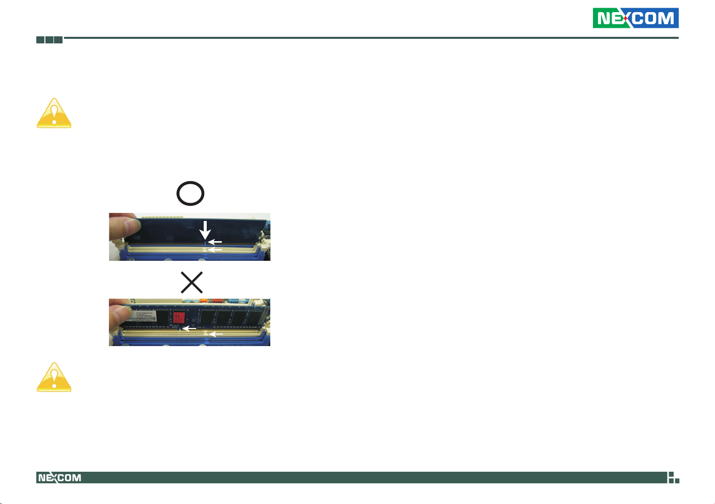
Step 1. Unlock a DIMM slot by pressing the retaining clips outward.
Step 2. Align a DIMM on the slot such that the notch on the DIMM
matches the break on the slot.
notch
break
notch
break
The DIMM only fits in one correct orientation. It will cause permanent damage to the motherboard and the DIMM if you force
the DIMM into the slot at incorrect orientation.
Step 3. Firmly insert the DIMM into the slot until the retaining clips at
both ends fully snap back in place and the DIMM is properly
seated.
Copyright © 2011 NEXCOM International Co., Ltd. All Rights Reserved.
8
NEX 883 User Manual
Page 20

Chapter 2: Installation
2.4 Expansion Slots
(PCI, PCI Express and mini-PCIe Slots)
There are 2 PCI slots, 2 PCI Express slots and 1 mini-PCIe slot on this motherboard.
PCI slots: PCI slots are used to install expansion cards that have the 32-bit
PCI interface.
PCIE slots: PCIE1 (PCIE x 16 slot; Blue) is used for PCI Express x 16 lane
width graphics cards. PCIE2 (PCIE x 4 slot; White) is used for PCI Express
x 4 lane width graphics cards.MINI_PCIE1 (mini-PCIe slot) is used for PCI
Express mini cards.
Installing an expansion card
Step 1. Before installing the expansion card, please make sure that the
power supply is switched off or the power cord is unplugged.
Please read the documentation of the expansion card and make
necessary hardware settings for the card before you start the
installation.
Step 2. Remove the system unit cover
(if your motherboard is already installed in a chassis).
Step 3. Remove the bracket facing the slot that you intend to use.
Keep the screws for later use.
Step 4. Align the card connector with the slot and press firmly until the
card is completely seated on the slot.
Step 5. Fasten the card to the chassis with screws.
Step 6. Replace the system cover.
Copyright © 2011 NEXCOM International Co., Ltd. All Rights Reserved.
9
NEX 883 User Manual
Page 21
Chapter 2: Installation
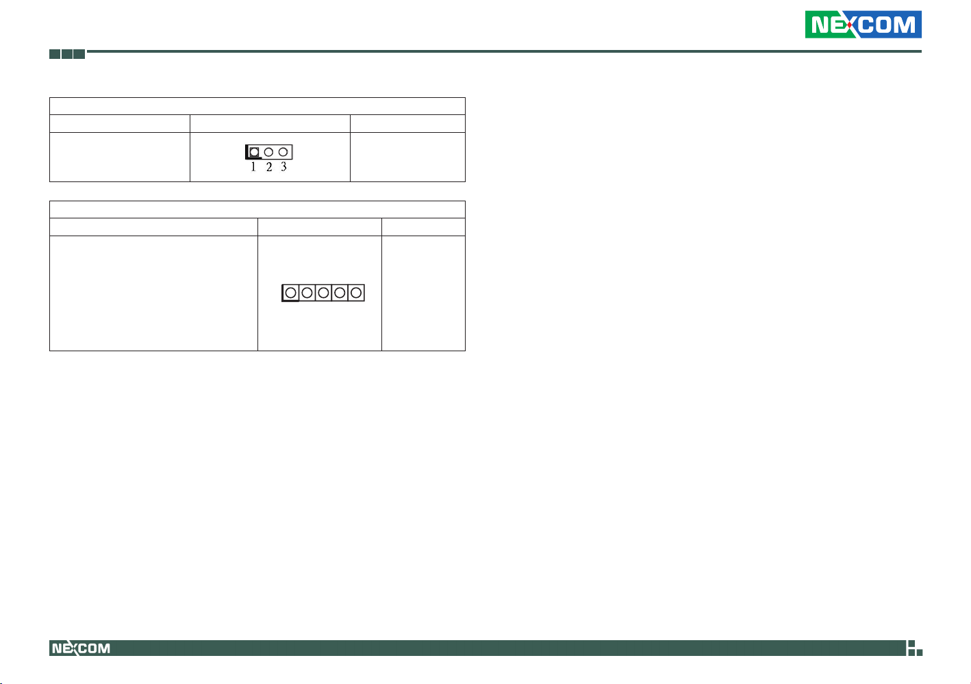
2.5 Jumper Settings
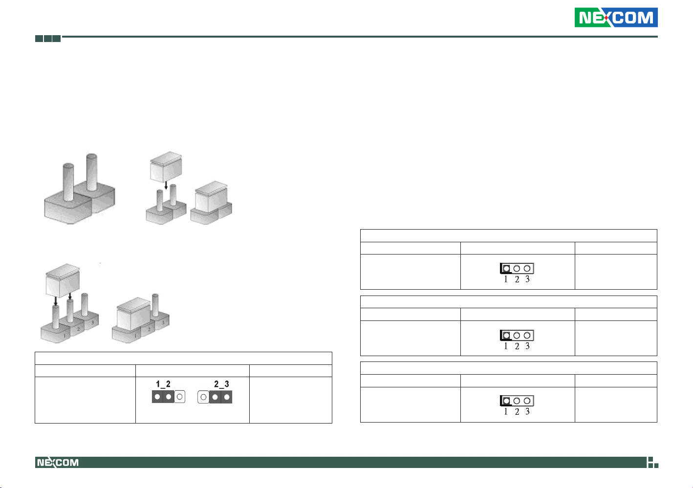
The illustration shows how jumpers are setup. When the jumper cap is
placed on pins, the jumper is “Short”. If no jumper cap is placed on pins,
the jumper is“Open”. The illustration shows a 3-pin jumper whose pin1
and pin2 are“Short”when jumper cap is placed on these 2 pins.
Three-Pin Jumpers: Pins 1 and 2 Are Short
Note: CLRCMOS1 allows you to clear the data in CMOS. To clear and
reset the system parameters to default setup, please turn off
the computer and unplug the power cord from the power supply.
After waiting for 15 seconds, use a jumper cap to short pin2
and pin3 on CLRCMOS1 for 5 seconds. However, please do not
clear the CMOS right after you update the BIOS. If you need to
clear the CMOS when you just finish updating the BIOS, you
must boot up the system first, and then shut it down before you
do the clear-CMOS action. Please be noted that the password,
date, time, user default profile and MAC address will be cleared
only if the CMOS battery is removed.
Panel Power Selection
Jumper Setting Description
(3-pin PNL_PWR1)
(see p.8, No. 2)
1-2 : +3V
2-3 : +5V
Clear CMOS Jumper
Jumper Setting Description
(3-pinCLRCMOS1)
(see p.8, No. 28)
Copyright © 2011 NEXCOM International Co., Ltd. All Rights Reserved.
Default Clear CMOS
Backlight Power Selection
Jumper Setting Description
(3-pin BKT_PWR1)
(see p.8, No. 3)
ATX/ AT Mode Selection
Jumper Setting Description
(3-pin PWR_JP1)
(see p.8, No. 41)
10
1-2 : +5V
2-3 : +12V
1-2 : AT Mode
2-3 : AXT Mode
NEX 883 User Manual
Page 22
Chapter 2: Installation
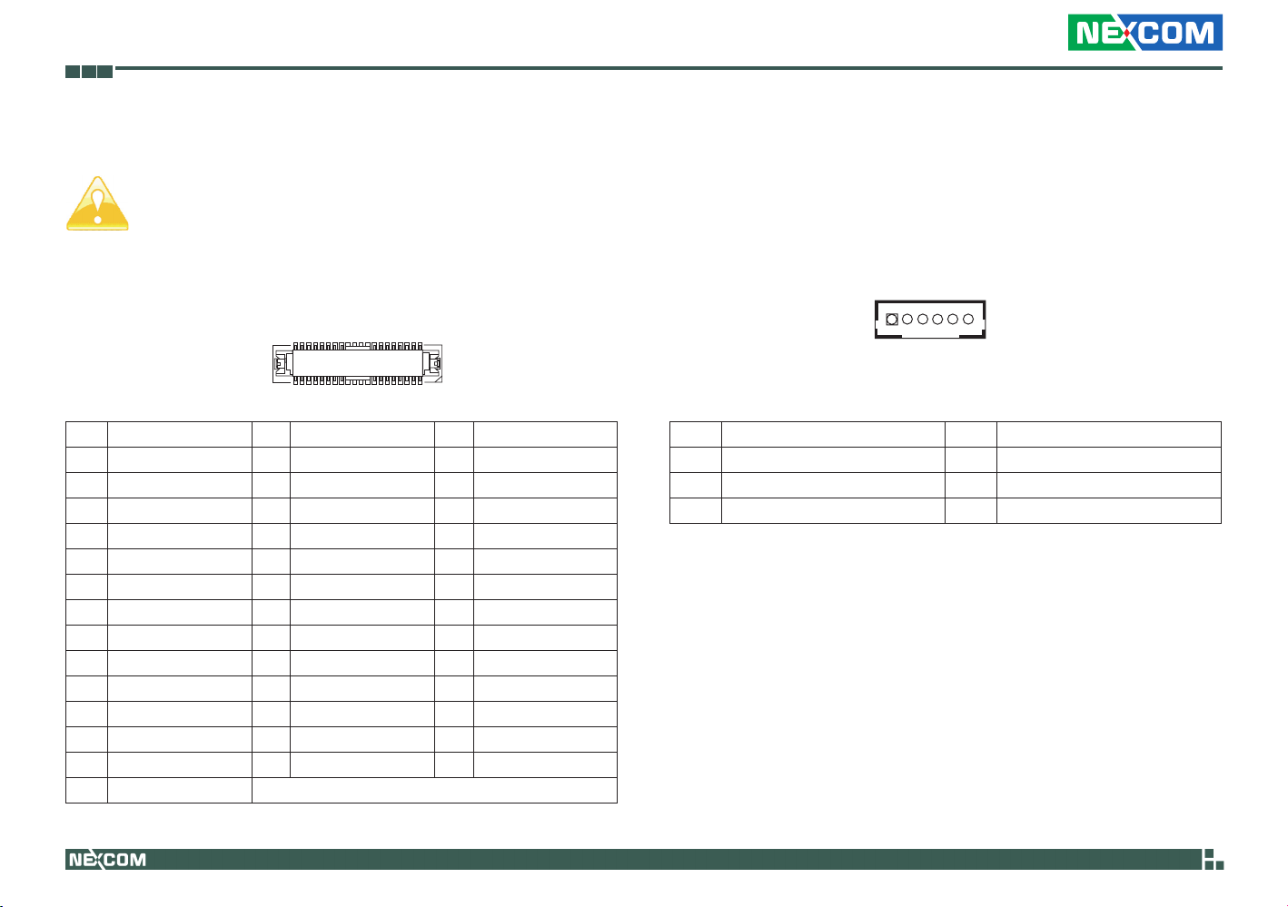
Digital Input/Output Power Selec
Jumper Setting Description
(3-pin JGPIO_PWR1)
(see p.8, No. 41)
COM Port Signal/ Power Setting Jumpers
Jumper Setting Description
(5-pin SET_CM2: see p.8, No. 6)
(5-pin SET_CM1: see p.8, No. 7)
(5-pin SET_CM6: see p.8, No. 17)
(5-pin SET_CM5: see p.8, No. 18)
(5-pin SET_CM4: see p.8, No. 19)
(5-pin SET_CM3: see p.8, No. 20)
1-2 : +12V
2-3 : +5V
1
1-2 : +12V
2-3 : +5V
Copyright © 2011 NEXCOM International Co., Ltd. All Rights Reserved.
11
NEX 883 User Manual
Page 23
Chapter 2: Installation
2.6 Onboard Headers and Connectors
Onboard headers and connectors are NOT jumpers. Do NOT
place jumper caps over these headers and connectors. Placing
jumper caps over the headers and connectors will cause permanent damage of the motherboard!
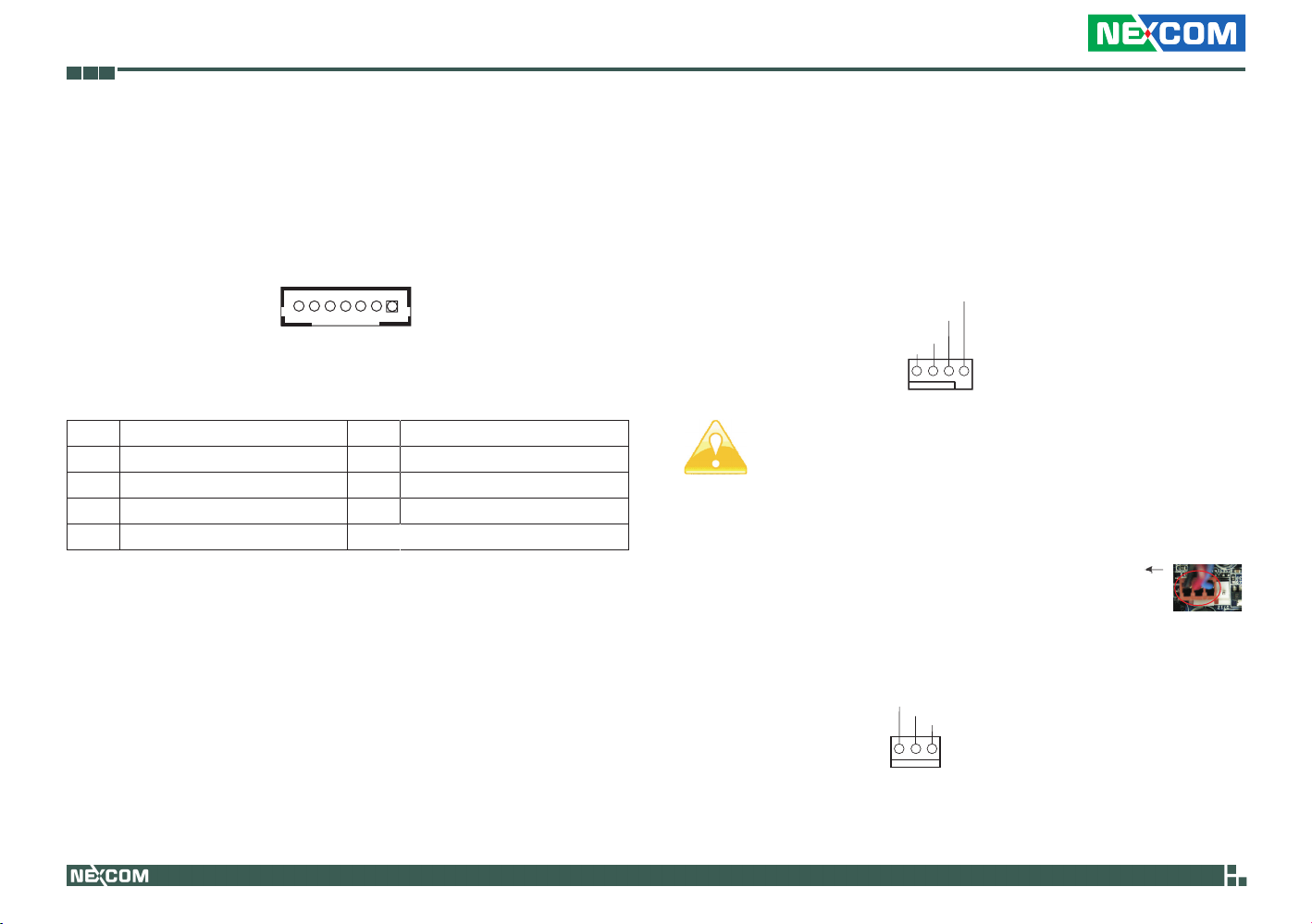
LVDS Panel Connector
(40-pin LVDS1)
(see p.8, No.1)
Pin Definition Pin Definition Pin Definition
1 R_LVDD 2 R_LVDD 3 +3V
4 LDDC_CLK 5 LDDC_DATA 6 LVDS_A_DATA0#
7 LVDS_A_DATA0 8 GND 9 LVDS_A_DATA1#
10 LVDS_A_DATA1 11 GND 12 LVDS_A_DATA2#
13 LVDS_A_DATA2 14 GND 15 LVDS_A_DATA3#
16 LVDS_A_DATA3 17 GND 18 LVDS_A_CLK#
19 LVDS_A_CLK 20 GND 21 LVDS_B_DATA0#
22 LVDS_B_DATA0 23 GND 24 LVDS_B_DATA1#
25 LVDS_B_DATA1 26 GND 27 LVDS_B_DATA2#
28 LVDS_B_DATA2 29 DPLVDD_EN 30 LVDS_B_DATA3#
31 LVDS_B_DATA3 32 GND 33 LVDS_B_CLK#
34 LVDS_B_CLK 35 GND 36 CON_LBKLT_EN_R
37 CON_LBKLT_CTL_R 38 LCD_BLT_VCC 39 LCD_BLT_VCC
40 LCD_BLT_VCC
1
2
39
40
Inverter Power Control Wafer
(6-pin BLT_PWR2)
(see p.8, No.4)
1
Pin Signal Name Pin Signal Name
1 GND 2 GND
3 CON_LBKLT_CTL 4 CON_LBKLT_EN
5 LCD_BLT_VCC 6 LCD_BLT_VCC
Copyright © 2011 NEXCOM International Co., Ltd. All Rights Reserved.
12
NEX 883 User Manual
Page 24
Chapter 2: Installation
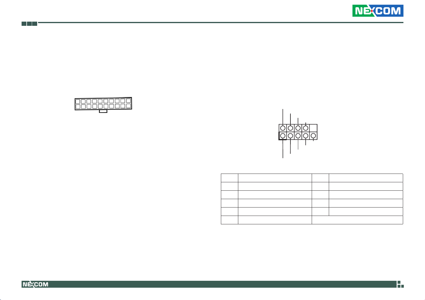
Backlight & Amp Volume Control
(7-pin BLT_VOL1)
(see p.8, No.4)
1
Pin Signal Name Pin Signal Name
1 GPIO_VOL_UP 2 GPIO_VOL_DW
3 PWRDN 4 GPIO_BLT_UP
5 GPIO_BLT_DW 6 GND
7 GND
CPU Fan Connectors
(4-pin CPU_FAN1)
(see p.8 No.9)
Please connect the CPU fan cable to the connector and match the
black wire to the ground pin.
FAN_SPEED_CONTROL
CPU_FAN_SPEED
+12V
GND
1 2 3 4
Though this motherboard provides 4-Pin CPU fan (Quiet Fan)
support, the 3-Pin CPU fan still can work successfully even without the fan speed control function. If you plan to connect the
3-Pin CPU fan to the CPU fan connector on this motherboard,
please connect it to Pin 1-3.
Pin 1-3 Connected
3-Pin Fan Installation
(3-pin CPU_FAN2)
(see p.8 No. 8)
Copyright © 2011 NEXCOM International Co., Ltd. All Rights Reserved.
13
GND
+12V
CPU_FAN_SPEED
NEX 883 User Manual
Page 25
Chapter 2: Installation
ATX Power Input Connector
(20-pin ATXPWR1)
(see p.8 No.10)
Please connect an ATX power supply to this connector.
COM Port Headers
(9-pin COM5: see p.8 No.11)
(9-pin COM6: see p.8 No. 12)
(9-pin COM4: see p.8 No. 13)
(9-pin COM3: see p.8 No. 14)
COM port headers support serial port modules.
RRXD1
DDTR#1
DDSR#1
CCTS#1
1
TTXD1
DDCD#1
Pin Signal Name Pin Signal Name
1 DDCD#1 2 TTXD1
3 GND 4 RRTS#1
5 RRI#1 6 RRXD1
7 DDTR#1 8 DDSR#1
9 CCIS#1
GND
RRI#1
RRTS#1
Copyright © 2011 NEXCOM International Co., Ltd. All Rights Reserved.
14
NEX 883 User Manual
Page 26
Chapter 2: Installation
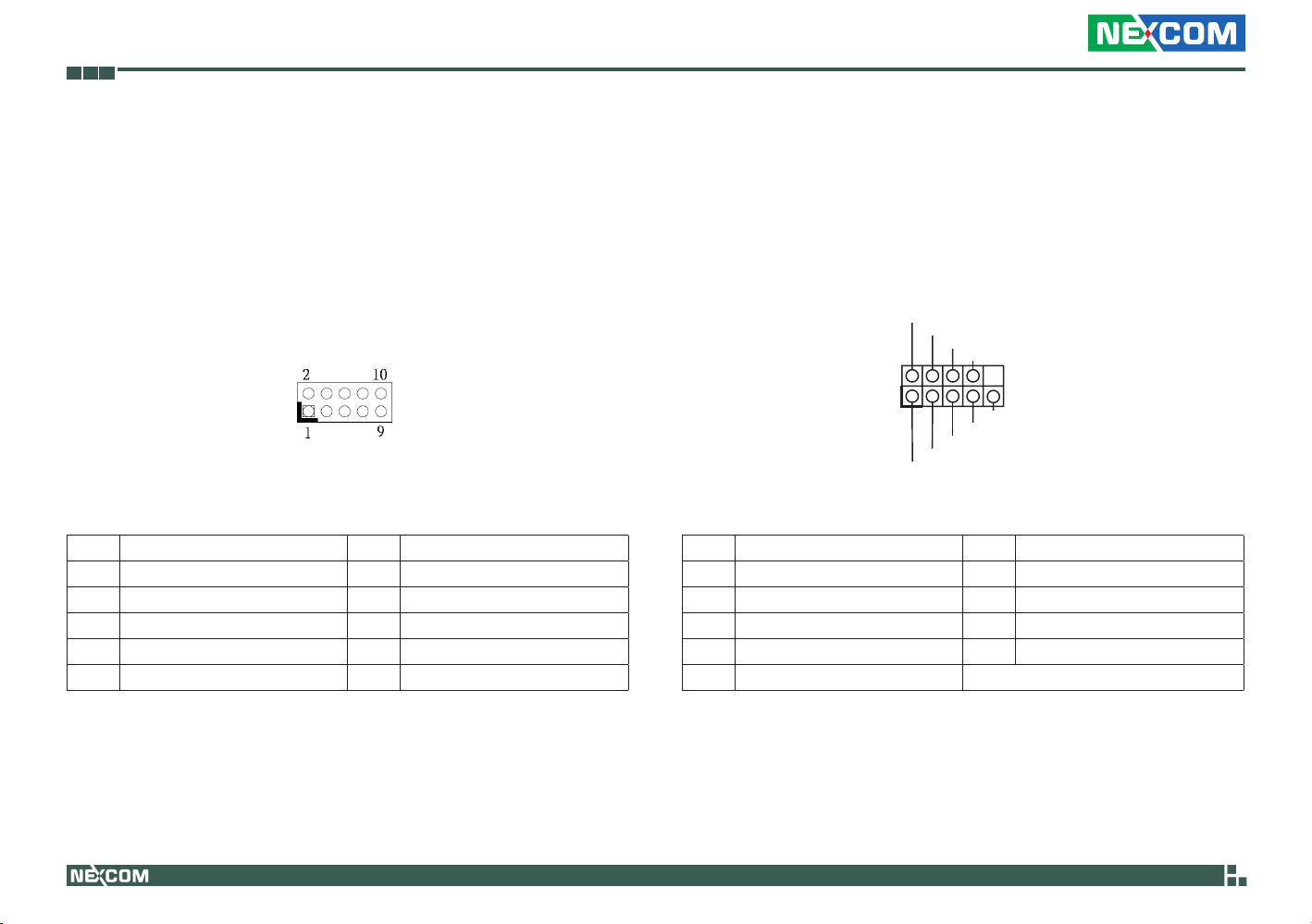
Digital Input/ Output Pin Header
(9-pin JGPIO1)
(see p.8, No.16)
Please connect the CPU fan cable to the connector and match the
black wire to the ground pin.
Pin Signal Name Pin Signal Name
1 Digital Output 0 2 Digital Input 0
3 Digital Output 1 4 Digital Input 1
5 Digital Output 2 6 Digital Input 2
7 Digital Output 3 8 Digital Input 3
9 JGPIO_PWR1 10 GND
System Panel Header
(9-pin PANEL1)
(see p.8, No.22)
This header accommodates system front panel functions.
PLED+
PLED-
PWRBTN#
GND
1
HDLED-
HDLED+
Pin Signal Name Pin Signal Name
1 HDLED+ 2 HDLED-
3 GND 4 RESET#1
5 DUMMY 6 PLED+
7 PLED- 8 PWRBTN#
9 GND
GND
DUMMY
RESET#
Copyright © 2011 NEXCOM International Co., Ltd. All Rights Reserved.
15
NEX 883 User Manual
Page 27
Chapter 2: Installation
Connect the power switch, reset switch and system status
indicator on the chassis to this header according to the pin assignments below. Note the positive and negative pins before
connecting the cables.
PWRBTN (Power Switch):
Connect to the power switch on the chassis front panel. You
may configure the way to turn off your system using the power
switch.
RESET (Reset Switch):
Connect to the reset switch on the chassis front panel. Press the
reset switch to restart the computer if the computer freezes and
fails to perform a normal restart.
PLED (System Power LED):
Connect to the power status indicator on the chassis front panel.
The LED is on when the system is operating. The LED keeps
blinking when the sys-tem is in S1/S3 sleep state. The LED is off
when the system is in S4 sleep state or powered off (S5).
HDLED (Hard Drive Activity LED):
Connect to the hard drive activity LED on the chassis front panel.
The LED is on when the hard drive is reading or writing data.
The front panel design may differ by chassis. A front panel mod-
ule mainly consists of power switch, reset switch, power LED,
hard drive activity LED, speaker and etc. When connecting your
chassis front panel module to this header, make sure the wire
assignments and the pin assign-ments are matched correctly.
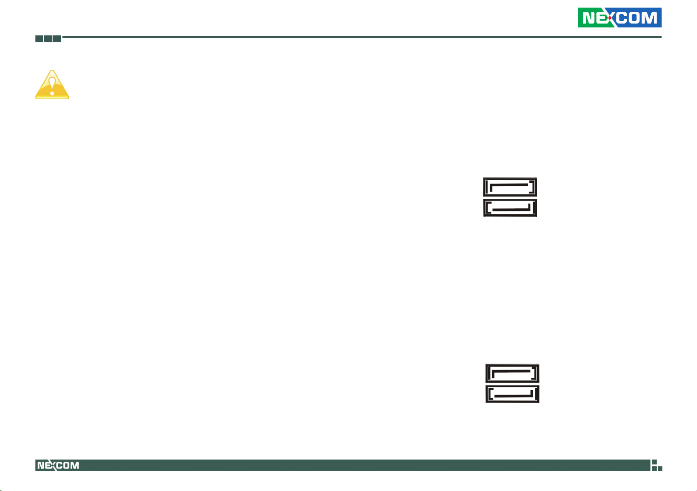
SATA2 Connectors
(SATA2_2: see p.8, No. 24)
(SATA2_3: see p.8, No. 25)
These two Serial ATA2 (SATA2) connectors support SATA data cables for
internal storage devices. The current SATA2 interface allows up to 3.0 Gb/s
data transfer rate.
SATA2_2
SATA2_3
SATA3 Connectors
(SATA3_1: see p.8, No. 26)
(SATA3_0: see p.8, No. 27)
These two Serial ATA3 (SATA3) connectors support SATA data cables for
internal storage devices. The current SATA3 interface allows up to 6.0 Gb/s
data transfer rate.
SATA3_0
SATA3_1
Copyright © 2011 NEXCOM International Co., Ltd. All Rights Reserved.
16
NEX 883 User Manual
Page 28
Chapter 2: Installation
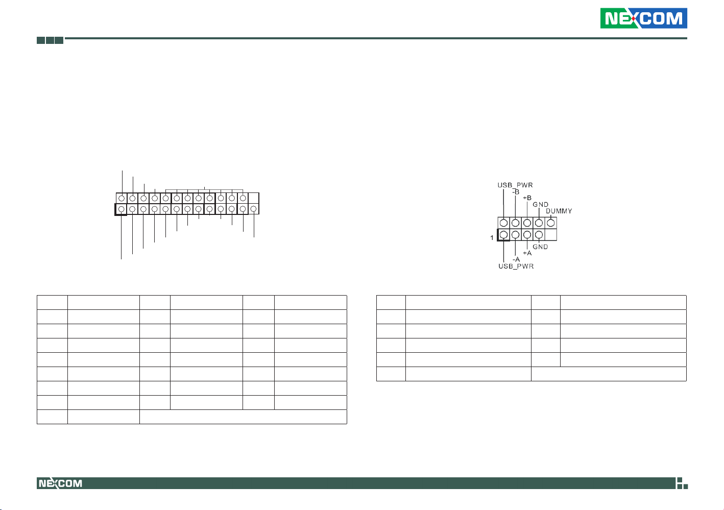
Print Port Header
(25-pin LPT1)
(see p.8, No. 29)
This is an interface for print port cable that allows convenient connection
of printer devices.
AFD#
ERROR#
PINIT#
SLIN#
1
SPD3
SPD2
SPD1
SPD0
STB#
Pin Signal Name Pin Signal Name Pin Signal Name
1 STB# 2 SPD0 3 SPD1
4 SPD2 5 SPD3 6 SPD4
7 SPD5 8 SPD6 9 SPD7
10 ACK# 11 BUSY 12 PE
13 SLCT 14 AFD# 15 ERROR#
16 PINIT# 17 SLIN# 18 GND
21 GND 22 GND 24 GND
25 GND
SPD4
SPD5
GND
SPD6
SPD7
ACK#
BUSY
PE
SLCT
USB 2.0 Headers
(USB12: see p.8, No. 30)
(9-pin USB6_7: see p.8, No. 34)
(9-pin USB8_9: see p.8, No. 32)
Besides four default USB 2.0 ports on the I/O panel, there are two USB 2.0 headers
and one USB 2.0 port on this motherboard. Each USB 2.0 header can support two
USB 2.0 ports.
Pin Signal Name Pin Signal Name
1 USB_PWR 2 -A
3 +A 4 GND
6 USB_PWR 7 -B
8 +B 9 GND
10 DUMMY
Copyright © 2011 NEXCOM International Co., Ltd. All Rights Reserved.
17
NEX 883 User Manual
Page 29
Chapter 2: Installation
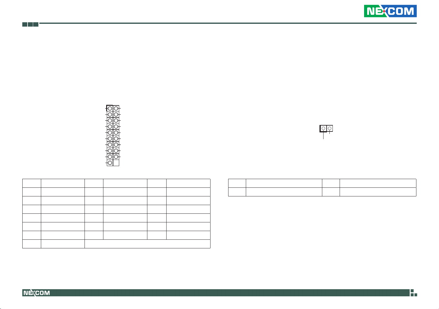
USB 3.0 Header
(19-pin USB3_10_11)
(see p.8 No. 31)
Besides two default USB 3.0 ports on the I/O panel, there is motherboard.
This USB 3.0 header can support two USB 3.0 ports.
1
Dum my
Int A_ PB _D+
Int A_ PB _D-
GND
Int A_ PB _SS TX +
Int A_ PB _SS TX -
GND
Int A_ PB _SS RX +
Int A_ PB _SS RX -
Vbu s
Pin Signal Name Pin Signal Name Pin Signal Name
1 Dummy 2 IntA_PB_D+ 3 IntA_PB_D-
4 GND 5 IntA_PB_SSTX+ 6 IntA_PB_SSTX-
7 GND 8 IntA_PB_SSRX+ 9 IntA_PB_SSRX+
10 Vbus 11 IntA_PA_D+ 12 IntA_PA_D-
13 GND 14 IntA_PA_SSTX+ 15 IntA_PA_SSTX-
16 GND 17 IntA_PA_SSRX+ 18 IntA_PA_SSRX-
19 Vbus
Int A_ PA_D +
Int A_ PA_D -
GND
Int A_ PA_S ST X+
Int A_ PA_S ST X-
GND
Int A_ PA_S SR X+
Int A_ PA_S SR X-
Vbu s
Chassis Intrusion Header
(2-pin CI2: see p.8, No. 35)
(2-pin CI1: see p.8, No. 36)
This motherboard supports CASE OPEN detection feature that detects if
the chassis cover has been removed. This feature requires a chassis with
chassis intrusion detection design.
1
GND
Signal
Pin Signal Name Pin Signal Name
1 Signal 2 GND
Copyright © 2011 NEXCOM International Co., Ltd. All Rights Reserved.
18
NEX 883 User Manual
Page 30
Chapter 2: Installation
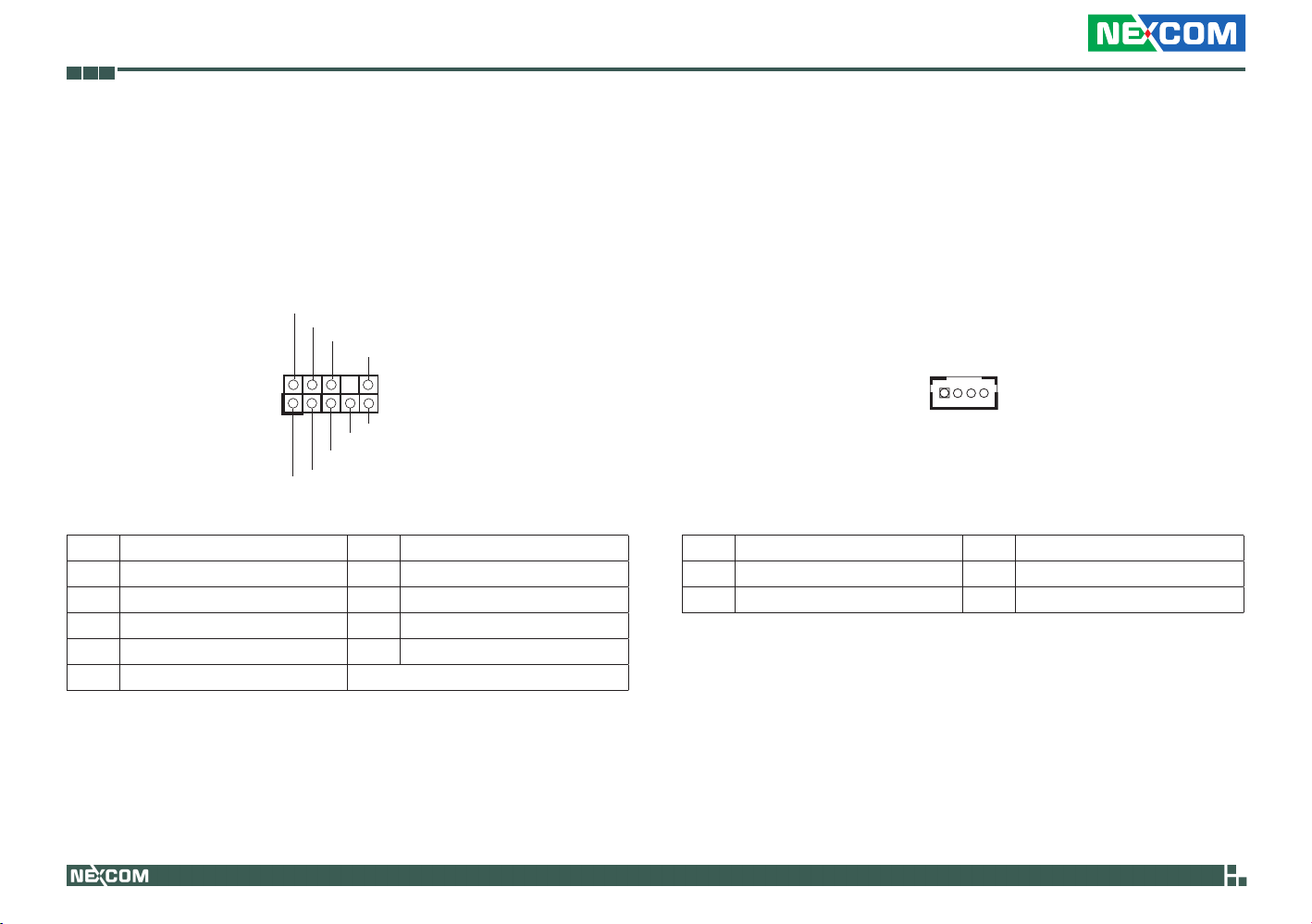
Front Panel Audio Header
(9-pin HD_AUDIO1)
(see p.8 No. 37)
This is an interface for front panel audio cable that allows convenient
connection and control of audio devices.
GND
PRESENCE#
MIC_RET
OUT_RET
1
OUT2_L
J_SENSE
OUT2_R
MIC2_R
MIC2_L
Pin Signal Name Pin Signal Name
1 MIC2_L 2 MIC2_R
3 OUT2_R 4 J_SENSE
5 OUT2_L 6 GND
7 PRESENCE# 8 MIC_RET
10 OUT_RET
3W Audio Amp Output Wafer
(4-pin SPEAKER1)
(see p.8, No. 38)
This motherboard supports CASE OPEN detection feature that detects if
the chassis cover has been removed. This feature requires a chassis with
chassis intrusion detection design.
1
Pin Signal Name Pin Signal Name
1 SPK L- 2 SPK L+
3 SPK R+ 4 SPK R-
Copyright © 2011 NEXCOM International Co., Ltd. All Rights Reserved.
19
NEX 883 User Manual
Page 31
Chapter 2: Installation
GND
+5V
GND
+12V
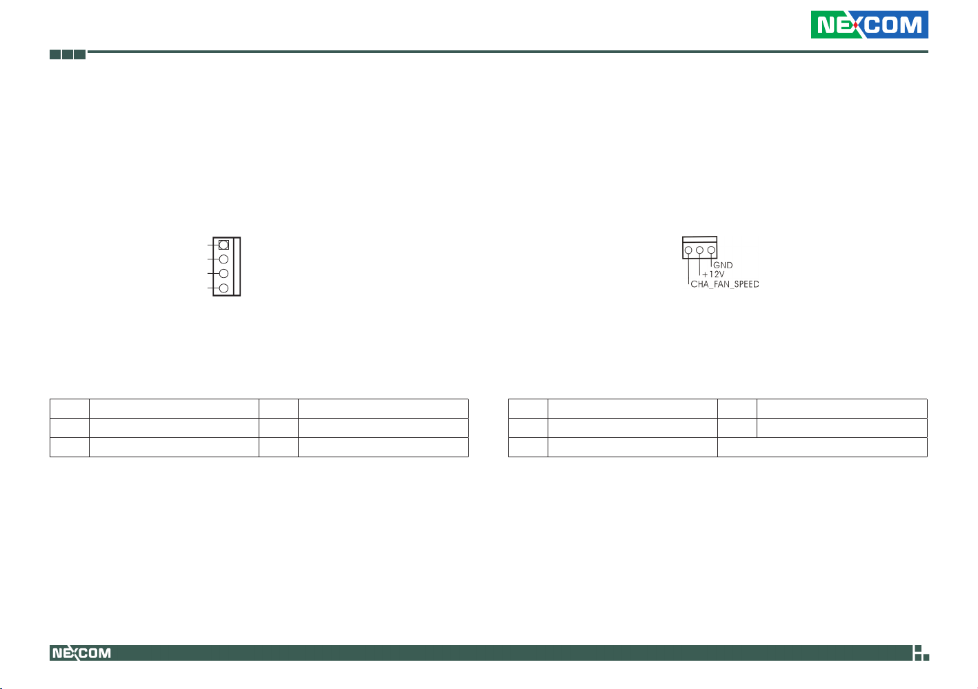
SATA Power Connectors
(4-pin JPWR1: see p.8, No. 40)
(4-pin JPWR2: see p.8, No. 42)
1
Pin Signal Name Pin Signal Name
1 +5V 2 GND
3 GND 4 +12V
Chassis Fan Connector
(3-pin CHA_FAN1)
(see p.8, No. 43)
Please connect the fan cable to the fan connector and match the black
wire to the ground pin.
Pin Signal Name Pin Signal Name
1 CHA FAN SPEED 2 +12V
3 GND
Copyright © 2011 NEXCOM International Co., Ltd. All Rights Reserved.
20
NEX 883 User Manual
Page 32
Chapter 2: Installation
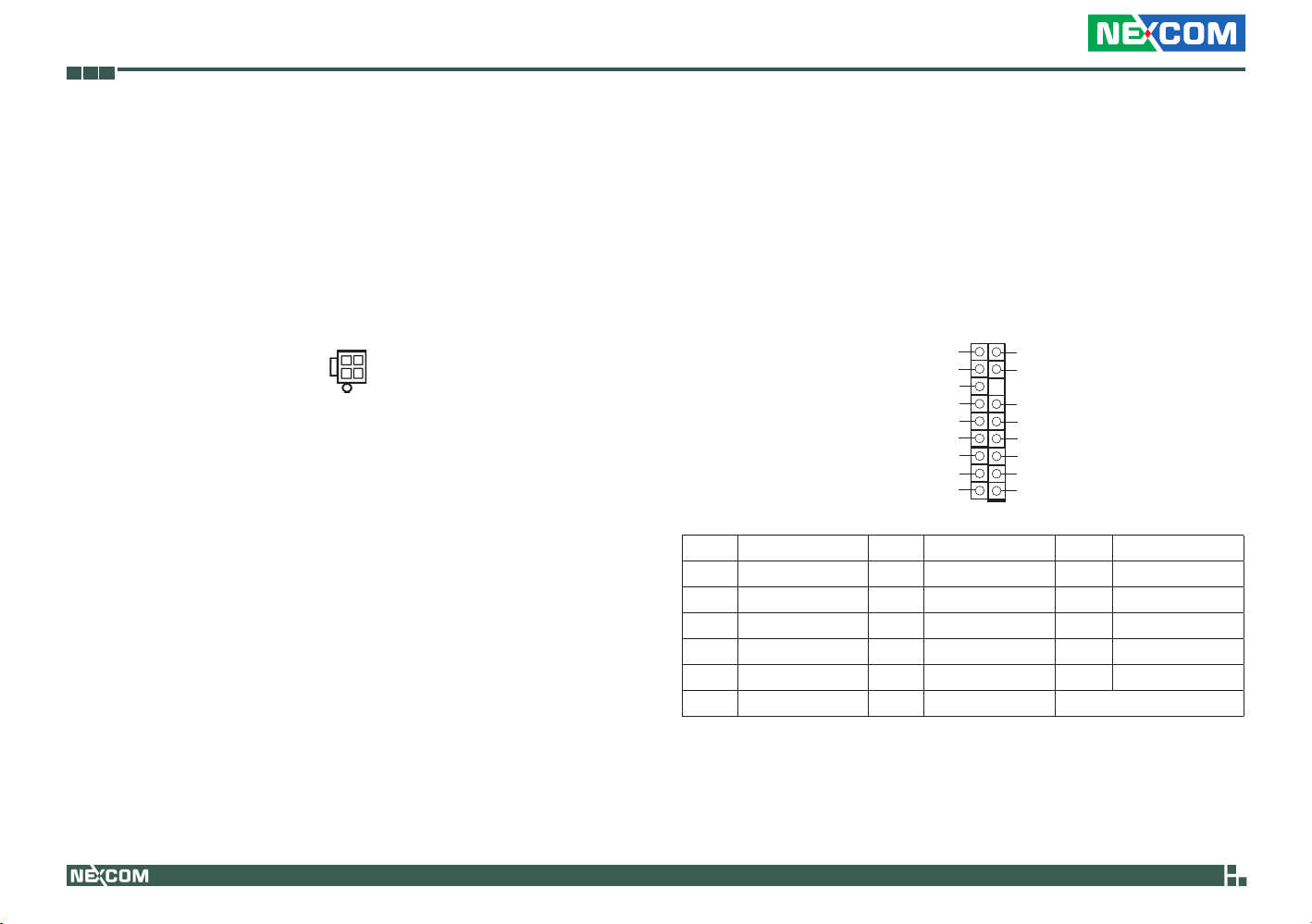
ATX 12V Power Input Connector
(4-pin ATX12V1)
(see p.8, No. 44)
Please connect an ATX 12V power supply to this connector.
(see p.8, No. 44)
TPM Header
(17-pin TPM1)
(see p.8, No. 23)
This connector supports a Trusted Platform Module (TPM) system, which
can securely store keys, digital certificates, passwords, and data. A TPM
system also helps enhance network security, protects digital identities, and
ensures platform integrity.
GND
SERIRQ#
S_PWRDWN#
GND
LAD1
LAD2
SMB_DATA_MAIN
SMB_CLK_MAIN
GND
Pin Signal Name Pin Signal Name Pin Signal Name
1 PCICLK 2 FRAME 3 PCIRST#
4 LAD3 5 +3V 6 LAD0
7 +3VSB 8 GND 9 GND
10 SMB_CLK_MAIN 11 SMB_DATA_MAIN 12 LAD2
13 LAD1 14 GND 15 S_PWRDWN#
16 SERIRQ# 17 GND
GND
+3VSB
LAD0
+3V
LAD3
PCIRST#
FRAME
PCICLK
1
Copyright © 2011 NEXCOM International Co., Ltd. All Rights Reserved.
21
NEX 883 User Manual
Page 33

Chapter 2: Installation
2.7 Serial ATA2 (SATA2)/ Serial ATA3
(SATA3) Hard Disks Installation
This motherboard adopts Intel® Q77 chipset that supports Serial ATA2
(SATA2) / Serial ATA3 (SATA3) hard disks and RAID (RAID 0, RAID 1 and
RAID 5) functions. You may install SATA2 / SATA3 hard disks on this motherboard for internal storage devices. This section will guide you to install
the SATA2 / SATA3 hard disks.
Step 1. Install the SATA2 / SATA3 hard disks into the drive bays of your
chassis.
Step 2. Connect the SATA power cable to the SATA2 / SATA3 hard disk.
Step 3. Connect one end of the SATA data cable to the motherboard’s
SATA2 / SATA3 connector.
Step 4. Connect the other end of the SATA data cable to the SATA2 /
SATA3 hard disk.
Copyright © 2011 NEXCOM International Co., Ltd. All Rights Reserved.
22
NEX 883 User Manual
Page 34
Chapter 2: Installation
2.8 Hot Plug and Hot Swap Functions
for SATA2/ SATA3 HDDs
This motherboard supports Hot Plug for SATA2/ SATA3 in RAID/ AHCI
mode. Intel® Q77 chipset provides hardware support for Advanced Host
controller Interface (AHCI), a new programming interface for SATA host
controllers developed through a joint industry effort.
NOTE:
What is Hot Plug Function?
If the SATA2/ SATA3 HDDs are NOT set for RAID configuration,
it is called “Hot Plug” for the action to insert and remove the
SATA2 / SATA3 HDDs while the system is still power-on and in
working condition.
However, please note that it cannot perform Hot Plug if the OS
has been installed into the SATA2/ SATA3 HDD.
What is Hot Swap Function?
If SATA2/ SATA3 HDDs are built as RAID 1 or RAID 5 then it
is called “Hot Swap” for the action to insert and remove the
SATA2/ SATA3 HDDs while the system is still power-on and in
working condition.
Copyright © 2011 NEXCOM International Co., Ltd. All Rights Reserved.
23
NEX 883 User Manual
Page 35

Chapter 2: Installation
2.9 Driver Installation Guide
To install the drivers to your system, please insert the support CD to your
optical drive first. Then, the drivers compatible to your system can be autodetected and listed on the support CD driver page. Please follow the order
from top to bottom to install those required drivers. Therefore, the drivers
you install can work properly.
Copyright © 2011 NEXCOM International Co., Ltd. All Rights Reserved.
24
NEX 883 User Manual
Page 36
Chapter 3: Uefi Setup Utility
ChaPter 3: uefI setuP utIlIty
3.1 Introduction
This section explains how to use the UEFI Setup Utility to configure your
system. The UEFI chip on the motherboard stores the UEFI Setup Utility.
You may run the UEFI Setup Utility when you start up the computer. Please
press <F2> or <Del> during the Power-On-Self-Test (POST) to enter the
UEFI Setup Utility, otherwise, POST will continue with its test routines.
If you wish to enter the UEFI Setup Utility after POST, restart the system by
pressing <Ctl> + <Alt> + <Delete>, or by pressing the reset button on the
system chassis. You may also restart by turning the system off and then
back on.
Because the UEFI software is constantly being updated, the
following UEFI setup screens and descriptions are for reference
purpose only, and they may not exactly match what you see on
your screen.
3.1.1 UEFI Menu Bar
The top of the screen has a menu bar with the following selections:
Main To set up the system time/date information
Advanced To set up the advanced UEFI features
H/W Monitor To display current hardware status
Boot To set up the default system device to locate and load
the Operating System
Security To set up the security features
Exit To exit the current screen or the UEFI SETUP UTILITY
Use < > key or < > key to choose among the selections on the menu
bar, and then press <Enter> to get into the sub screen. You can also use
the mouse to click your required item.
Copyright © 2011 NEXCOM International Co., Ltd. All Rights Reserved.
25
NEX 883 User Manual
Page 37
Chapter 3: Uefi Setup Utility
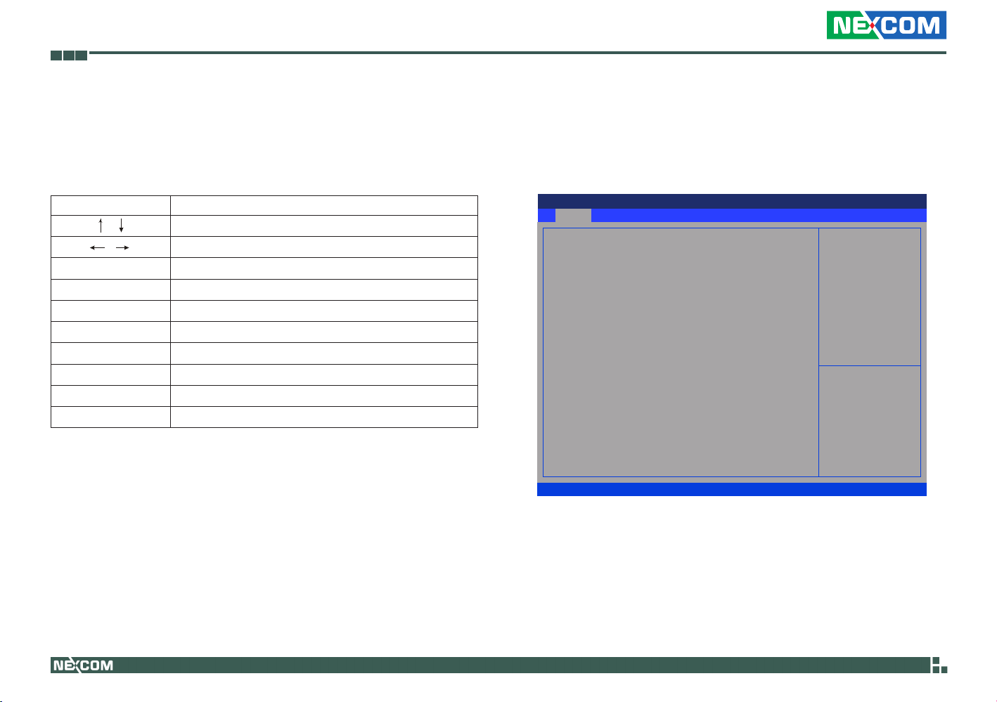
3.1.2 Navigation Keys
Please check the following table for the function description of each
navigation key.
Navigation Key(s) Function Description
/ Moves cursor left or right to select Screens
/ Moves cursor up or down to select items
+ / - To change option for the selected items
<Enter> To bring up the selected screen
<F1> To display the General Help Screen
<F7> Discard changes
<F9> To load optimal default values for all the settings
<F10> To save changes and exit the UEFI SETUP UTILITY
<F12> Print screen
<ESC> To jump to the Exit Screen or exit the current screen
3.2 Main Screen
When you enter the UEFI Setup Utility, the Main screen will appear and
display the system overview.
Aptio Setup Utility - Copyright (C) 2011 American Megatrends, Inc.
Advanced
UEFI Version
Processor Type
Processor Speed
Microcode Update
Cache Size
Total Memory
DDR3_A1
DDR3_A2
DDR3_B1
DDR3_B2
System Date
System Time
Version 2.14.1219. Copyright (C) 2011 American Megatrends, Inc.
H/W Monitor
: IMB-370-L L0.03
: Intel(R) Core(TM) i7-3770 CPU @ 3.40GHz
: 3400MHZ
: 306A8/10
: 8192KB
: 1024 MB with 64MB Shared Memory and
2MB Single-Channel Memory Mode
: None
: None
: None
: 1024 MB (DDR3-1333)
[Tue 10/30/2012]
[17:24:08]
Boot SecurityMain
Exit
Set the Date. Use Tab to switch
between Data elements.
→←: Select Screen
↑↓: Select Item
Enter: Select
+/-: Change Opt.
F1: General Help
F7: Discard Changes
F9: Load UEFI Defaults
F10: Save & Exit
F12: Print Screen
ESC: Exit
Copyright © 2011 NEXCOM International Co., Ltd. All Rights Reserved.
26
NEX 883 User Manual
Page 38

Chapter 3: Uefi Setup Utility
3.3 Advanced Screen
In this section, you may set the configurations for the following items:
CPU Configuration, Northbridge Configuration, Southbridge
Configuration, Storage Configuration, Intel® Rapid Start Technology,
Intel(R) Smart Connect Technology, AMT Configuration, Super IO Configuration, ACPI Configuration and USB Configuration.
Aptio Setup Utility - Copyright (C) 2011 American Megatrends, Inc.
Advanced
CPU conguration
North Bridge Conguraton
South Bridge Conguration
Storage Conguration
Intel(R) Rapid Start Technology
Intel(R) Smart Connect Technology
AMT Conguration
Super IO Conguration
ACPI Conguration
USB Conguration
UEFI Update Utility
Instant Flash
H/W Monitor
Boot SecurityMain
Exit
Congure North Bridge Settings.
→←: Select Screen
↑↓: Select Item
Enter: Select
+/-: Change Opt.
F1: General Help
F7: Discard Changes
F9: Load UEFI Defaults
F10: Save & Exit
F12: Print Screen
ESC: Exit
Instant Flash
Instant Flash is a UEFI flash utility embedded in Flash ROM. This convenient UEFI update tool allows you to update system UEFI without entering
operating systems first like MS-DOS or Windows®. Just launch this tool
and save the new UEFI file to your USB flash drive, floppy disk or hard
drive, then you can update your UEFI only in a few clicks without preparing
an additional floppy diskette or other complicated flash utility. Please be
noted that the USB flash drive or hard drive must use FAT32/16/12 file system. If you execute Instant Flash utility, the utility will show the UEFI files
and their respective information. Select the proper UEFI file to update your
UEFI, and reboot your system after UEFI update process completes.
Version 2.14.1219. Copyright (C) 2011 American Megatrends, Inc.
Setting wrong values in this section may cause the system to
malfunction.
Copyright © 2011 NEXCOM International Co., Ltd. All Rights Reserved.
27
NEX 883 User Manual
Page 39
Chapter 3: Uefi Setup Utility
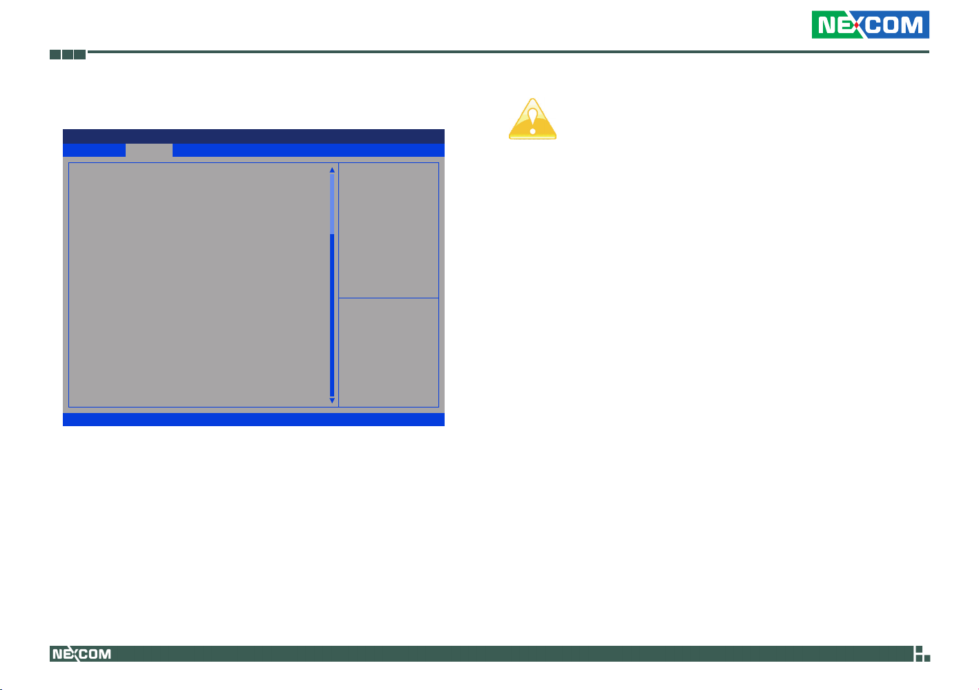
3.3.1 CPU Configuration
Aptio Setup Utility - Copyright (C) 2011 American Megatrends, Inc.
Advanced
Intel VT-x Technology
Intel SMX Technology
64-bit
CPU Ratio
Intel SpeedStep Technology
Intel Turbo Boost Technology
Long Duration Power Limit
Long Duration Maintained
Short Duration Power Limit
Primary plane Current Limit
Secondary Plane Current Limit
Intel Hyper Threading Technology
Active Processor Cores
Enhanced Halt State(C1E)
CPU C3 State Support
CPU C6 State Support
Package C State Support
Cpu Thermal Throtting
NO-Execute Memory Protection
Intel Virtualization Technology
Hardware Prefetcher
Adjacent Cache Line Prefetch
Version 2.14.1219. Copyright (C) 2011 American Megatrends, Inc.
CPU Ratio
Use this item to change the ratio value of this motherboard.
ntel SpeedStep Technology
Intel SpeedStep technology is Intel’s new power saving technology.
Processors can switch between multiple frequencies and voltage points to
enable power saving. The default value is [Enabled]. Configuration options:
[Enabled] and [Disabled]. If you install Windows® VistaTM/ 7 and want to
enable this function, please set this item to [Enabled]. This item will be
hidden if the current CPU does not support Intel SpeedStep technology.
Supported
Supported
Supported
[Auto]
[Enabled]
[Enabled]
Auto
[Auto]
Auto
Auto
Auto
[Enabled]
[All]
[Enabled]
[Enabled]
[Enabled]
[Auto]
[Enabled]
[Enabled]
[Enabled]
[Enabled]
[Enabled]
To turn on/off prefetching of
adjacent cache lines.
→←: Select Screen
↑↓: Select Item
Enter: Select
+/-: Change Opt.
F1: General Help
F7: Discard Changes
F9: Load UEFI Defaults
F10: Save & Exit
F12: Print Screen
ESC: Exit
Please note that enabling this function may reduce CPU voltage
and lead to system stability or compatibility issues with some
power supplies. Please set this item to [Disabled] if above issues
occur.
Intel Turbo Boost Technology
Use this item to enable or disable Intel Turbo Boost Mode Technology.
Turbo Boost Mode allows processor cores to run faster than marked
frequency in specific conditions. The default value is [Enabled].
Long Duration Power Limit
Use this item to configure long duration power limit in watts. The default
value is [Auto].
Long Duration Maintained
Use this item to configure time window which the long duration power is
maintained. The default value is [Auto].
Short Duration Power Limit
Use this item to configure short duration power limit in watts.
The default value is [Auto].
Primary Plane Current Limit
Use this item to configure the maximum instantaneous current allowed
for the primary plane. The default value is [Auto].
Secondary Plane Current Limit
Use this item to configure the maximum instantaneous current allowed
for the secondary plane. The default value is [Auto].
Copyright © 2011 NEXCOM International Co., Ltd. All Rights Reserved.
28
NEX 883 User Manual
Page 40

Chapter 3: Uefi Setup Utility
Intel Hyper Threading Technology
To enable this feature, a computer system with an Intel processor that supports Hyper-Threading technology and an operating system that includes
optimization for this technology, such as Microsoft® Windows® XP/ VistaTM/
7 is required. Set to [Enabled] if using Microsoft® Windows® XP, VistaTM, 7,
or Linux kernel version 2.4.18 or higher. This option will be hidden if the
installed CPU does not support Hyper-Threading technology.
Active Processor Cores
Use this item to select the number of cores to enable in each processor
package. The default value is [All].
Enhance Halt State (C1E)
All processors support the Halt State (C1). The C1 state is supported
through the native processor instructions HLT and MWAIT and requires no
hardware support from the chipset. In the C1 power state, the processor
maintains the context of the system caches.
CPU C3 State Support
Use this to enable or disable CPU C3 (ACPI C2) report to OS.
CPU C6 State Support
Use this to enable or disable CPU C6 (ACPI C3) report to OS.
Package C State Support
Selected option will program into C State package limit register. The default value is [Auto].
CPU Thermal Throttling
You may select [Enabled] to enable CPU internal thermal control mechanism to keep the CPU from overheating.
No-Execute Memory Protection
No-Execution (NX) Memory Protection Technology is an enhancement
to the IA-32 Intel Architecture. An IA-32 processor with “No Execute (NX)
Memory Protection” can prevent data pages from being used by malicious
software to execute codes. This option will be hidden if the current CPU
does not support No-Excute Memory Protection.
Intel Virtualization Technology
When this option is set to [Enabled], a VMM (Virtual Machine Architecture)
can utilize the additional hardware capabilities provided by Vanderpool
Technology. This option will be hidden if the installed CPU does not
support Intel Virtualization Technology.
Hardware Prefetcher
Use this item to turn on/off the MLC streamer prefetcher.
Adjacent Cache Line Prefetch
Use this item to turn on/off prefetching of adjacent cache lines.
Copyright © 2011 NEXCOM International Co., Ltd. All Rights Reserved.
29
NEX 883 User Manual
Page 41
Chapter 3: Uefi Setup Utility
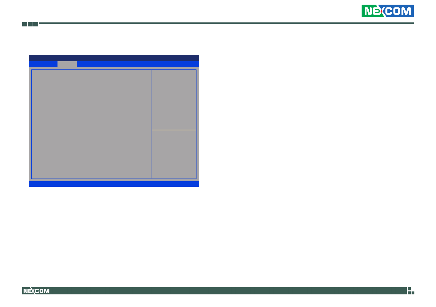
3.3.2 North Bridge Configuration
Aptio Setup Utility - Copyright (C) 2011 American Megatrends, Inc.
Main
VT-d Capability
DRAM Frequency
Primary Graphics Adaper
VT-d
PCIE1 Link Speed
Share Memory
IGPU Multi-Monitor
RenderStandby
Deep Render Standby
Actlve LVDS
Panel Type Selection
Primary IGFX Boot Display
Advanced Chipset PCIPnP Security
Supported
[Auto]
[PCI Express]
[Disabled]
[Atuo]
[Atuo]
[Disabled]
[Enabled]
[Enabled]
[Enabled]
[1600x900/18-bit/2-...]
[VBIOS Default]
Version 2.14.1219. Copyright (C) 2011 American Megatrends, Inc.
DRAM Frequency
If [Auto] is selected, the motherboard will detect the memory module(s)
inserted and assign the appropriate frequency automatically.
Primary Graphics Adapter
This allows you to select [Onboard], [PCI] or [PCI Express] as the boot
graphic adapter priority. The default value is [PCI Express].
VT-d
Use this item to enable/ disable Intel® Virtualization Technology for
Directed I/O.
Exit
Select DRAM Frecuency.
→←: Select Screen
↑↓: Select Item
Enter: Select
+/-: Change Opt.
F1: General Help
F7: Discard Changes
F9: Load UEFI Defaults
F10: Save & Exit
F12: Print Screen
ESC: Exit
PCIE1 Link Speed
This allows you to select PCIE 1 Link Speed. The default value is [Auto].
Share Memory
This allows you to set onboard VGA share memory feature. The default
value is [Auto].
IGPU Multi-Monitor
This allows you to enable or disable IGPU Multi-Monitor. The default value
is [Disabled]. If you wish to install a PCI Express card under Windows® XP
/ VistaTM OS, please disable this option.
Render Standby
Use this to enable or disable Render Standby by Internal Graphics Device.
The default value is [Enabled].
Deep Render Standby
This allows you to enable or disable Deep Render Standby. The default
value is [Enabled].
Active LVDS
Use this to enable or disable the LVDS. The default value is [Enabled].
Panel Type Selection
Use this to select panel type.
Primary IGFX Boot Display
Select the Video Device which will be activated during POST. This has no
effect if external graphics present. Secondary boot display selection will
appear based on your selection. VGA modes will be supported only on
primary display. Configuration options: [VBIOS Default], [CRT], [DVI],
[HDMI] and [LVDS]. The default value is [VBIOS Default].
Copyright © 2011 NEXCOM International Co., Ltd. All Rights Reserved.
30
NEX 883 User Manual
Page 42
Chapter 3: Uefi Setup Utility
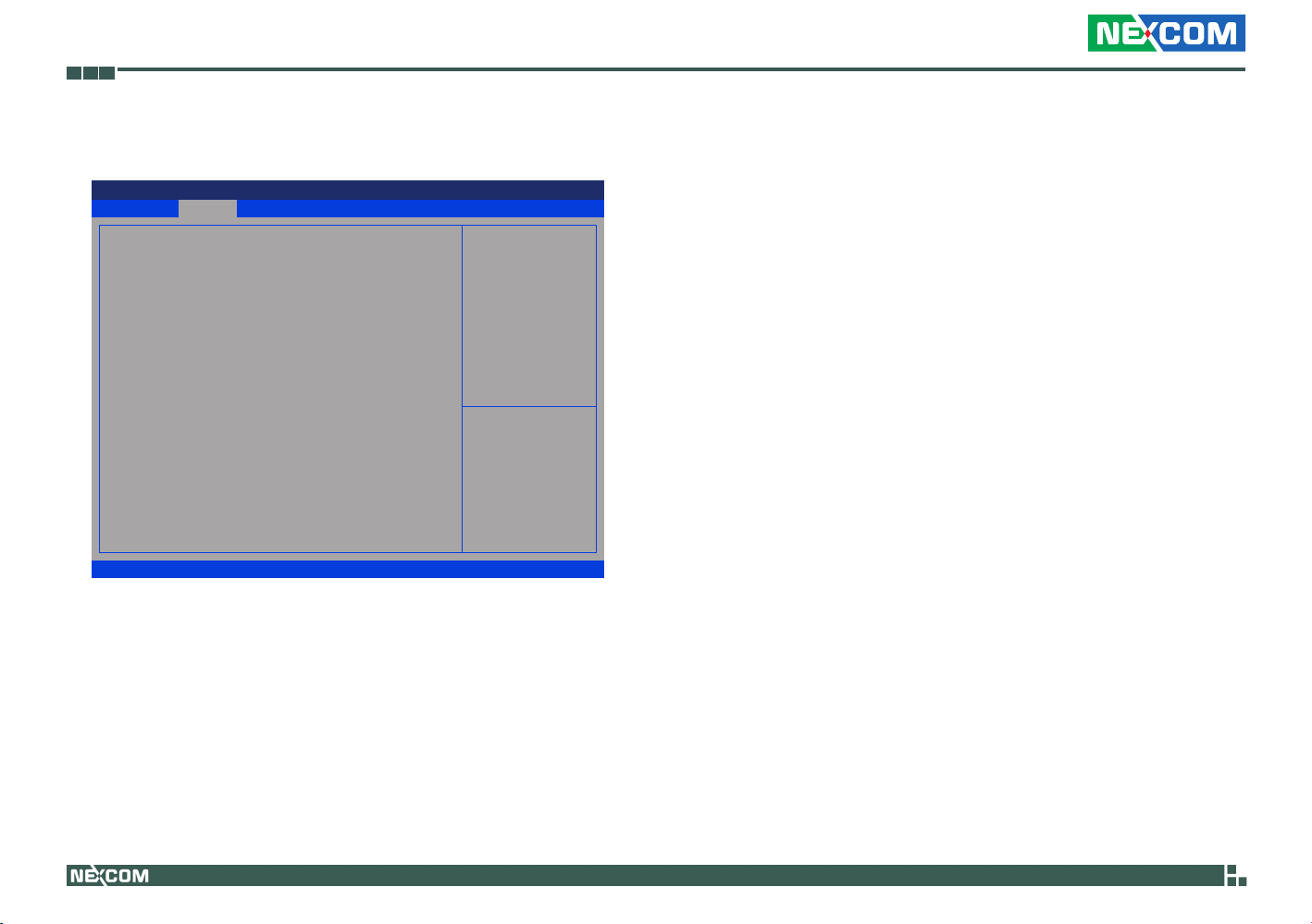
3.3.3 South Bridge Configuration
Aptio Setup Utility - Copyright (C) 2011 American Megatrends, Inc.
Main
Onboard HD Audio
Front Pane1
Onboard HDMI HD Audio
Onboard LAN 1
Onboard LAN 2
Deep Sleep
Restore on AC/Power Loss
Advanced Chipset PCIPnP Security
[Auto]
[Atuo]
[Enabled]
[Enabled]
[Enabled]
[Disabled]
[Power Off]
Version 2.14.1219. Copyright (C) 2011 American Megatrends, Inc.
Onboard HD Audio
Select [Auto], [Enabled] or [Disabled] for the onboard HD Audio feature. If
you select [Auto], the onboard HD Audio will be disabled when PCI Sound
Card is plugged.
Front Panel
Select [Auto] or [Disabled] for the onboard HD Audio Front Panel.
Onboard HDMI HD Audio
This allows you to enable or disable the Onboard HDMI HD Audio feature.
Exit
Atuo/Enabled/Disabled
Onboard HD Audio.
→←: Select Screen
↑↓: Select Item
Enter: Select
+/-: Change Opt.
F1: General Help
F7: Discard Changes
F9: Load UEFI Defaults
F10: Save & Exit
F12: Print Screen
ESC: Exit
Onboard LAN 1
This allows you to enable or disable the Onboard LAN 1 feature.
Onboard LAN 2
This allows you to enable or disable the Onboard LAN 2 feature.
Deep Sleep
Mobile platforms support Deep S4/S5 in DC only and desktop platforms
support Deep S4/S5 in AC only. The default value is [Disabled].
Restore on AC/Power Loss
This allows you to set the power state after an unexpected AC/power loss.
If [Power Off] is selected, the AC/power remains off when the power
recovers. If [Power On] is selected, the AC/power resumes and the
system starts to boot up when the power recovers.
Copyright © 2011 NEXCOM International Co., Ltd. All Rights Reserved.
31
NEX 883 User Manual
Page 43
Chapter 3: Uefi Setup Utility
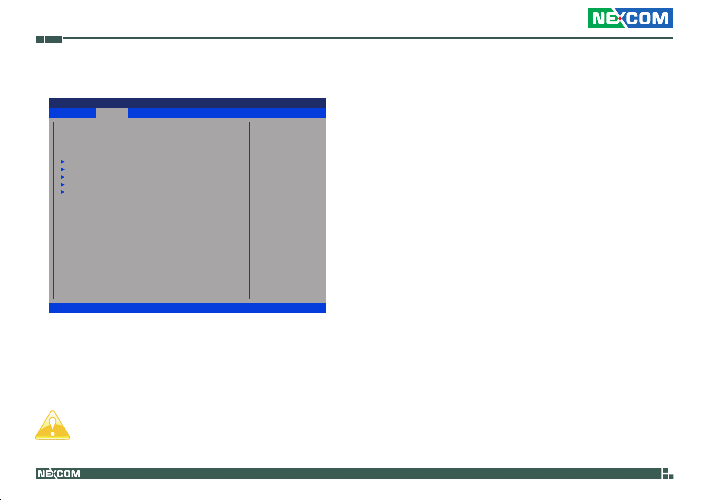
3.3.4 Storage Configuration
Aptio Setup Utility - Copyright (C) 2011 American Megatrends, Inc.
Main
SATA Controller(s)
SATA Mode Selection
Hard Disk S.M.A.R.T
SATA3_0 :Not Detected
SATA3_1 :Not Detected
SATA3_2 :Not Detected
SATA3_3 :Not Detected
MINI_SATA1 :Not Detected
Advanced Chipset PCIPnP Security
[Enabled]
[IDE]
[Disabled]
Version 2.14.1219. Copyright (C) 2011 American Megatrends, Inc.
SATA Controller(s)
Use this item to enable or disable the SATA Controller feature.
SATA Mode Selection
Use this to select SATA mode. Configuration options: [IDE Mode], [AHCI
Mode]and [RAID Mode]. The default value is [IDE Mode].
Exit
Enable or disable SATA
Device.
→←: Select Screen
↑↓: Select Item
Enter: Select
+/-: Change Opt.
F1: General Help
F7: Discard Changes
F9: Load UEFI Defaults
F10: Save & Exit
F12: Print Screen
ESC: Exit
Hard Disk S.M.A.R.T.
Use this item to enable or disable the S.M.A.R.T. (Self-Monitoring, Analysis, and Reporting Technology) feature. Configuration options: [Disabled]
and [Enabled].
AHCI (Advanced Host Controller Interface) supports NCQ and
other new features that will improve SATA disk performance but
IDE mode does not have these advantages.
Copyright © 2011 NEXCOM International Co., Ltd. All Rights Reserved.
32
NEX 883 User Manual
Page 44
Chapter 3: Uefi Setup Utility
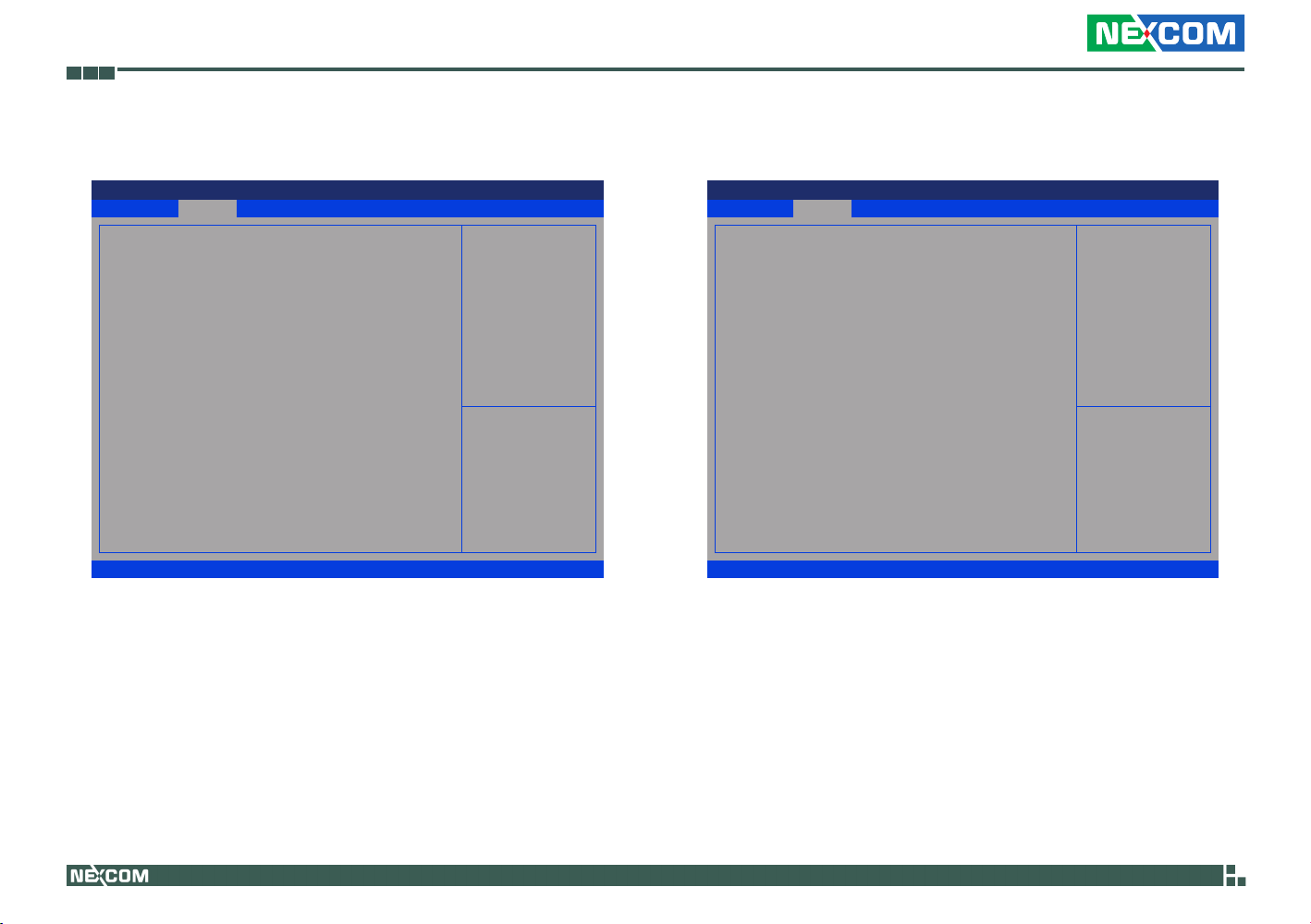
3.3.5 Intel® Rapid Start Technology 3.3.6 Intel® Smart Connect Technology
Aptio Setup Utility - Copyright (C) 2011 American Megatrends, Inc.
Main
Intel(R) Rapid Start Technology [Disabled]
Advanced Chipset PCIPnP Security
Version 2.14.1219. Copyright (C) 2011 American Megatrends, Inc.
Exit
→←: Select Screen
↑↓: Select Item
Enter: Select
+/-: Change Opt.
F1: General Help
F7: Discard Changes
F9: Load UEFI Defaults
F10: Save & Exit
F12: Print Screen
ESC: Exit
Intel® Rapid Start Technology
Use this item to enable or disable Intel® Rapid Start Technology. Intel®
Rapid Start Technology is a new zero power hibernation mode which
allows users to resume in just 5-6 seconds. The default is [Disabled].
Aptio Setup Utility - Copyright (C) 2011 American Megatrends, Inc.
Main
Intel(R) Smart Connect Technology [Disabled]
Advanced Chipset PCIPnP Security
Version 2.14.1219. Copyright (C) 2011 American Megatrends, Inc.
Exit
Enable/Disable Intel(R)
Smart Connect
Technology.
→←: Select Screen
↑↓: Select Item
Enter: Select
+/-: Change Opt.
F1: General Help
F7: Discard Changes
F9: Load UEFI Defaults
F10: Save & Exit
F12: Print Screen
ESC: Exit
Intel® Smart Connect Technology
Use this item to enable or disable Intel® Smart Connect Technology. Intel®
Smart Connect Technology keeps your e-mail and social networks, such
as Twitter, Facebook, etc. updated automatically while the computer is in
sleep mode. The default is [Enabled].
Copyright © 2011 NEXCOM International Co., Ltd. All Rights Reserved.
33
NEX 883 User Manual
Page 45
Chapter 3: Uefi Setup Utility
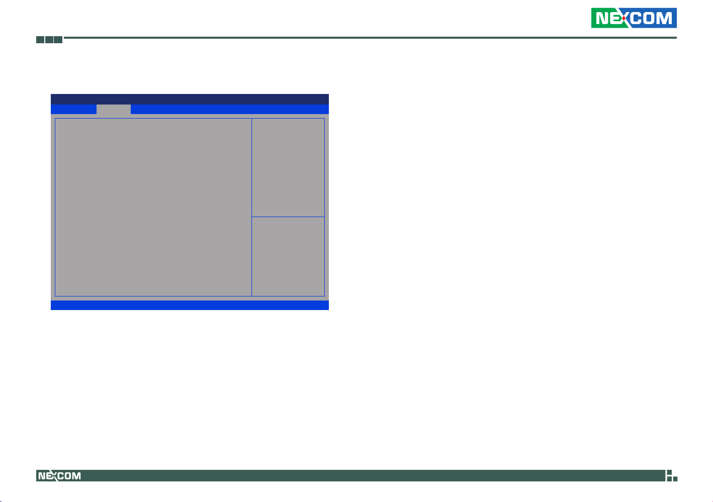
3.3.7 AMT Technology
Aptio Setup Utility - Copyright (C) 2011 American Megatrends, Inc.
Advanced
Intel AMT
BIOS Hotkey Pressed
MEBx Selection Screen
Hide Un-Congure ME Conrmation
MEBx Debug Message Output
Un-Congure ME
Amt Wait Timer
Disable ME
ASF
Activate Remote Assistance Process
USB Congure
PET Progress
AMT CIRA Timeout
WatchDog
OS Timer
BIOS Timer
Version 2.14.1219. Copyright (C) 2011 American Megatrends, Inc.
Intel AMT
Use this to enable or disable Intel(R) Active Management Technology BIOS
Extension. The default is [Enabled].
BIOS Hotkey Pressed
Use this to enable or disable BIOS hotkey press. The default is [Disabled].
MEBx Selection Screen
Use this to enable or disable MEBx Selection Screen. The default is
[Disabled].
[Enabled]
[Disabled]
[Disabled]
[Disabled]
[Disabled]
[Disabled]
0
[Disabled]
[Enabled]
[Disabled]
[Enabled]
[Enabled]
0
[Disabled]
0
0
Enable/Disable Intel (R)
Active Management Technology
BIOS Extension.
Note : iAMT H/W is always
enabled.
This option just controls the
BIOS extension execution.
If enabled, this requires
additional rmware in the
SPI devic.
→←: Select Screen
↑↓: Select Item
Enter: Select
+/-: Change Opt.
F1: General Help
F7: Discard Changes
F9: Load UEFI Defaults
F10: Save & Exit
F12: Print Screen
ESC: Exit
Hide Un-Congure ME Conrmation
Hide Un-Configure ME without password confirmation prompt. The
default is [Disabled].
MEBx Debug Message Output
Use this to enable or disable MEBx Debug Message Output. The default is
[Disabled].
Un-Congure ME
Un-Configure ME without password. The default is [Disabled].
Amt Wait Timer
Set timer to wait before sending ASF_GET_BOOT_OPTIONS.
Disable ME
Set ME to Soft Temporary Disabled. The default is [Disabled].
ASF
Use this to enable or disable Alert Specification Format. The default is
[Enabled].
Activate Remote Assistance Process
Trigger CIRA boot. The default is [Disabled].
USB Congure
Use this to enable or disable USB Configure function. The default is
[Enabled].
PET Progress
User can enable or disable PET Events progress to receive PET events or
not. The default is [Enabled].
WatchDog
Use this to enable or disable WatchDog Timer. The default is [Disabled].
Copyright © 2011 NEXCOM International Co., Ltd. All Rights Reserved.
34
NEX 883 User Manual
Page 46
Chapter 3: Uefi Setup Utility
3.3.8 Super IO Configuration
Aptio Setup Utility - Copyright (C) 2011 American Megatrends, Inc.
Advanced
Super IO Conguration
COM1 Conguration
COM2 Conguration
COM3 Conguration
COM4 Conguration
COM5 Conguration
COM6 Conguration
LPT1 Port Conguration
WDT Timeout Reset [Disabled]
Version 2.14.1219. Copyright (C) 2011 American Megatrends, Inc.
COM1 Conguration
Use this to set parameters of COM1.
COM2 Conguration
Use this to set parameters of COM2.
COM3 Conguration
Use this to set parameters of COM3.
COM4 Conguration
Use this to set parameters of COM4.
Set Parameters of COM1
→←: Select Screen
↑↓: Select Item
Enter: Select
+/-: Change Opt.
F1: General Help
F7: Discard Changes
F9: Load UEFI Defaults
F10: Save & Exit
F12: Print Screen
ESC: Exit
COM5 Conguration
Use this to set parameters of COM5.
COM6 Conguration
Use this to set parameters of COM6.
LPT1 Port Conguration
Use this set parameters of the onboard parallel port.
WDT Timeout Reset
This allows users to enable/disable the Watch Dog Timer timeout to reset system.
The default value is [Disabled].
Copyright © 2011 NEXCOM International Co., Ltd. All Rights Reserved.
35
NEX 883 User Manual
Page 47
Chapter 3: Uefi Setup Utility
3.3.9 ACPI Configuration
Aptio Setup Utility - Copyright (C) 2011 American Megatrends, Inc.
Advanced
Suspend to RAM
Check Ready Bit
ACPI HPET Table
PS/2 Keyboard Power on
PCI Devices Power on
Ring-In Power on
RTC Alarm Power on
USB Keyboard/Remote Power on
USB Mouse Power on
Version 2.14.1219. Copyright (C) 2011 American Megatrends, Inc.
Suspend to RAM
Use this item to select whether to auto-detect or disable the Suspend-toRAM feature. Select [Auto] will enable this feature if the OS supports it.
Check Ready Bit
Use this item to enable or disable the feature Check Ready Bit.
ACPI HPET Table
Use this item to enable or disable ACPI HPET Table. The default value is
[Enabled]. Please set this option to [Enabled] if you plan to use this
motherboard to submit Windows® VistaTM certification.
[Auto]
[Enabled]
[Enabled]
[Disabled]
[Disabled]
[Disabled]
[By OS]
[Disabled]
[Disabled]
Select the highest ACPI sleep
state the system will enter when
the suspend button is pressed.
→←: Select Screen
↑↓: Select Item
Enter: Select
+/-: Change Opt.
F1: General Help
F7: Discard Changes
F9: Load UEFI Defaults
F10: Save & Exit
F12: Print Screen
ESC: Exit
PS/2 Keyboard Power On
Use this item to enable or disable PS/2 keyboard to turn on the system
from the power-soft-off mode.
PCI Devices Power On
Use this item to enable or disable PCI devices to turn on the system from
the power-soft-off mode.
Ring-In Power On
Use this item to enable or disable Ring-In signals to turn on the system
from the power-soft-off mode.
RTC Alarm Power On
Use this item to enable or disable RTC (Real Time Clock) to power on the
system.
USB Keyboard/Remote Power On
Use this item to enable or disable USB Keyboard/Remote to power on the
system.
USB Mouse Power On
Use this item to enable or disable USB Mouse to power on the system.
Copyright © 2011 NEXCOM International Co., Ltd. All Rights Reserved.
36
NEX 883 User Manual
Page 48
Chapter 3: Uefi Setup Utility
3.3.10 USB Configuration
Aptio Setup Utility - Copyright (C) 2011 American Megatrends, Inc.
Advanced
USB 2.0 Controller
USB 2.0 Controller
Legacy USB Support
Legacy USB 3.0 Support
Version 2.14.1219. Copyright (C) 2011 American Megatrends, Inc.
USB 2.0 Controller
Use this item to enable or disable the use of USB 2.0 controller.
USB 3.0 Controller
Use this item to enable or disable the use of USB 3.0 controller.
[Enabled]
[Enabled]
[Enabled]
[Enabled]
To enable or disable USB 2.0
Controller.
→←: Select Screen
↑↓: Select Item
Enter: Select
+/-: Change Opt.
F1: General Help
F7: Discard Changes
F9: Load UEFI Defaults
F10: Save & Exit
F12: Print Screen
ESC: Exit
Legacy USB Support
Use this option to select legacy support for USB devices. There are four
configuration options: [Enabled], [Auto], [Disabled] and [UEFI Setup Only].
The default value is [Enabled]. Please refer to below descriptions for the
details of these four options:
[Enabled] - Enables support for legacy USB.
[Auto] - Enables legacy support if USB devices are connected.
[Disabled] - USB devices are not allowed to use under legacy OS and UEFI
setup when [Disabled] is selected. If you have USB compatibility issues, it is
recommended to select [Disabled] to enter OS.
[UEFI Setup Only] - USB devices are allowed to use only under UEFI setup
and Windows / Linux OS.
Legacy USB 3.0 Support
Use this option to enable or disable legacy support for USB 3.0 devices.
The default value is [Enabled].
Copyright © 2011 NEXCOM International Co., Ltd. All Rights Reserved.
37
NEX 883 User Manual
Page 49
Chapter 3: Uefi Setup Utility
3.4 Hardware Health Event Monitoring
Screen
In this section, it allows you to monitor the status of the hardware on your
system, including the parameters of the CPU temperature, motherboard
temperature, CPU fan speed, chassis fan speed, and the critical voltage.
Aptio Setup Utility - Copyright (C) 2011 American Megatrends, Inc.
Advanced
Hardware Health Event Monitoring
CPU Temperature
M/B Temperature
CPU_FAN1 Speed
CPU_FAN2 Speed
CHA_FAN1 Speed
Vcore
+3.30V
+5.00V
+12.00V
CPU_FAN1 & Setting
CHA_FAN1 Setting
Over Temperature Protection
Case Open Feature
H/W Monitor
Boot SecurityMain
: 42 OC
: 36 OC
: 4440 RPM
: N/A
: N/A
: +1.128V
: +3.360V
: +5.064V
: +12.249V
[Full on]
[Full on]
[Enabled]
[Disabled]
Exit
Quiet Fan Function Control
→←: Select Screen
↑↓: Select Item
Enter: Select
+/-: Change Opt.
F1: General Help
F7: Discard Changes
F9: Load UEFI Defaults
F10: Save & Exit
F12: Print Screen
ESC: Exit
CPU_FAN1 & 2 Setting
This allows you to set CPU fan 1 & 2’s speed. Configuration options:
[Full On] and [Automatic Mode]. The default value is [Full On].
CHA_FAN1 Setting
This allows you to set chassis fan 1’s speed. Configuration options:
[Full On] and [Automatic Mode]. The default value is [Full On].
Over Temperature Protection
Use this to enable or disable Over Temperature Protection. The default
value is [Enabled].
Case Open Feature
This allows you to enable or disable case open detection feature.
The default is value [Disabled].
Clear Status
This option appears only when the case open has been detected. Use this
option to keep or clear the record of previous chassis intrusion status.
Version 2.14.1219. Copyright (C) 2011 American Megatrends, Inc.
Copyright © 2011 NEXCOM International Co., Ltd. All Rights Reserved.
38
NEX 883 User Manual
Page 50
Chapter 3: Uefi Setup Utility
3.5 Boot Screen
In this section, it will display the available devices on your system for you to
configure the boot settings and the boot priority.
Aptio Setup Utility - Copyright (C) 2011 American Megatrends, Inc.
Advanced
Boot Option Priorities
Setup Prompt Timeout
Bootup Num-Lock
PCI ROM Priority
Boot From Onboard LAN
Boot Failure Guard
Boot Failure Guard Count
Version 2.14.1219. Copyright (C) 2011 American Megatrends, Inc.
H/W Monitor
Boot SecurityMain
1
[On]
[Legacy ROM]
[Disabled]
[Enabled]
[3]
Exit
Number of seconds to wait for
setup activation key.
65535 (0xFFF) means indenite
waiting.
→←: Select Screen
↑↓: Select Item
Enter: Select
+/-: Change Opt.
F1: General Help
F7: Discard Changes
F9: Load UEFI Defaults
F10: Save & Exit
F12: Print Screen
ESC: Exit
Setup Prompt Timeout
This shows the number of seconds to wait for setup activation key.
65535(0XFFFF) means indefinite waiting.
Bootup Num-Lock
If this item is set to [On], it will automatically activate the Numeric Lock
function after boot-up.
PCI ROM Priority
Use this item to adjust PCI ROM Priority. The default value is
[Legacy ROM].
Boot From Onboard LAN
Use this item to enable or disable the Boot From Onboard LAN feature.
Boot Failure Guard
Enable or disable the feature of Boot Failure Guard.
Boot Failure Guard Count
Use this item to configure Boot Failure Guard Count.
Copyright © 2011 NEXCOM International Co., Ltd. All Rights Reserved.
39
NEX 883 User Manual
Page 51
Chapter 3: Uefi Setup Utility
3.6 Security Screen
In this section, you may set, change or clear the supervisor/ user password
for the system.
Aptio Setup Utility - Copyright (C) 2011 American Megatrends, Inc.
Advanced
Supervisor Password
User Password
Supervisor Password
User Password
Version 2.14.1219. Copyright (C) 2011 American Megatrends, Inc.
H/W Monitor
Boot SecurityMain
Not Installed
Not Installed
Exit
Install or Change the Password.
→←: Select Screen
↑↓: Select Item
Enter: Select
+/-: Change Opt.
F1: General Help
F7: Discard Changes
F9: Load UEFI Defaults
F10: Save & Exit
F12: Print Screen
ESC: Exit
Copyright © 2011 NEXCOM International Co., Ltd. All Rights Reserved.
40
NEX 883 User Manual
Page 52
Chapter 3: Uefi Setup Utility
3.7 Exit Screen
In this section, you may set, change or clear the supervisor/ user password
for the system.
Aptio Setup Utility - Copyright (C) 2011 American Megatrends, Inc.
Advanced
Save Changes and Exit
Discard Changes and Exit
Discard Changes
Load UEFI Defaults
Launch EFI Shell from lesystem device
Version 2.14.1219. Copyright (C) 2011 American Megatrends, Inc.
H/W Monitor
Boot SecurityMain
Exit
Exit system setup after saving
the changes.
F10 key can be used for this
operation.
→←: Select Screen
↑↓: Select Item
Enter: Select
+/-: Change Opt.
F1: General Help
F7: Discard Changes
F9: Load UEFI Defaults
F10: Save & Exit
F12: Print Screen
ESC: Exit
Save Changes and Exit
When you select this option, it will pop-out the following message,
“Save configuration changes and exit setup?” Select [OK] to save the
changes and exit the UEFI SETUP UTILITY.
Discard Changes and Exit
When you select this option, it will pop-out the following message,
“Discard changes and exit setup?” Select [OK] to exit the UEFI SETUP
UTILITY without saving any changes.
Discard Changes
When you select this option, it will pop-out the following message,
“Discard changes?” Select [OK] to discard all changes.
Load UEFI Defaults
Load UEFI default values for all the setup questions. F9 key can be used for
this operation.
Launch EFI Shell from lesystem device
Attempts to Launch EFI Shell application (Shell64.efi) from one of the available filesystem
devices.
Copyright © 2011 NEXCOM International Co., Ltd. All Rights Reserved.
41
NEX 883 User Manual
Page 53

Chapter 4: Software Support
ChaPter 4: software suPPort
4.1 Install Operating System
This motherboard supports various Microsoft® Windows® operating systems: 7/ 7 64-bit/ VistaTM/ VistaTM 64-bit/ XP/ XP 64-bit. Because motherboard settings and hardware options vary, use the setup procedures in this
chapter for general reference only. Refer your OS documentation for more
information.
4.2 Support CD Information
The Support CD that came with the motherboard contains necessary drivers and useful utilities that enhance the motherboard’s features.
4.2.1 Running The Support CD
To begin using the support CD, insert the CD into your CD-ROM drive.
The CD automatically displays the Main Menu if“AUTORUN”is enabled in
your computer. If the Main Menu did not appear automatically, locate and
double click on the file“ASSETUP.EXE”from the BIN folder in the Support
CD to display the menus.
4.2.2 Drivers Menu
The Drivers Menu shows the available device’s drivers if the system detects
installed devices. Please install the necessary drivers to activate the devices.
4.2.3 Utilities Menu
The Utilities Menu shows the application software that the motherboard
supports. Click on a specific item then follow the installation wizard to
install it.
4.2.4 Contact Information
If you need to contact NEXCOM or want to know more about NEXCOM,
you’re welcome to visit NEXCOM website at http://www.NEXCOM.com; or
you may contact your dealer for further information.
Copyright © 2011 NEXCOM International Co., Ltd. All Rights Reserved.
42
NEX 883 User Manual
 Loading...