


NEXCOM International Co., Ltd.
Industrial Computing Solutions
Embedded Computing (Industrial Motherboard)
NEX 880/890
User Manual
NEXCOM International Co., Ltd.
Published June 2011
www.nexcom.com

Contents
Contents
Preface
Copyright ............................................................................................. iv
Disclaimer
Acknowledgements
Regulatory Compliance Statements
Declaration of Conformity
RoHS Compliance
Warranty and RMA
Safety Information
Installation Recommendations
Safety Precautions
Technical Support and Assistance
Conventions Used in this Manual
Global Service Contact Information
Package Contents
Ordering Information
............................................................................................. iv
.............................................................................. iv
....................................................... iv
...................................................................... iv
................................................................................... v
................................................................................ vi
................................................................................vii
................................................................vii
.................................................................................viii
........................................................... ix
........................................................... ix
......................................................... x
..................................................................................xii
............................................................................xiii
Chapter 1: Product Introduction
Overview ................................................................................................1
Key Features
Hardware Specifications
Getting to Know NEX 880/890
.......................................................................................1
..........................................................................2
...............................................................4
Chapter 2: Jumpers and Connectors
Before You Begin ....................................................................................5
Precautions
Jumper Settings
Locations of the Jumpers and Connectors
Jumpers
CMOS Clear Select
ME Clear Select
BIOS CS# SEL Select
Connectors Pin Definitions
External I/O Interface
Internal Connectors
.............................................................................................5
...................................................................................... 6
...............................................7
..................................................................................................8
.............................................................................8
..................................................................................8
...........................................................................9
....................................................................10
........................................................................10
PS/2 Keyboard and PS/2 Mouse Ports
COM1 and COM2 Ports (RS232)
VGA and DVI-D Ports
LAN1 and USB0/1 Ports
LAN2 and USB2/3 Ports
Audio Jacks
SATA 3.0 Ports
SATA 2.0 Ports
USB Connectors
FP Audio Connector
FP Control Connector
ATX Power Connector
ATX Power Connector
.................................................................................13
...................................................................11
...............................................................12
...............................................................12
.......................................................................... 14
.............................................................................14
.............................................................................14
...........................................................................15
.....................................................................15
..................................................................16
..................................................................16
..................................................................17
...........................................10
..................................................10
Copyright © 2011 NEXCOM International Co., Ltd. All Rights Reserved.
ii
NEX 880/890 User Manual

Contents
SMBus Connector ........................................................................17
GPIO Connector
Port 80 Debug Connector
CPU Fan Connector
System Fan Connectors
PCIe x16 Slot
PCIe x8 Slot
PCIe x4 Slot
..........................................................................18
............................................................18
.....................................................................19
................................................................19
...............................................................................20
.................................................................................21
.................................................................................22
Chapter 3: BIOS Setup
About BIOS Setup .................................................................................23
When to Configure the BIOS
Entering Setup
Legends
BIOS Setup Utility
Main
Advanced
Chipset
Boot
Security
Save & Exit
......................................................................................24
................................................................................................24
.................................................................................. 25
................................................................................................ 25
......................................................................................... 26
............................................................................................37
................................................................................................. 41
............................................................................................42
....................................................................................... 43
.................................................................23
Appendix A: Watchdog Timer
WDT Programming Guide .....................................................................44
Appendix B: GPI/O Programming Guide
GPIO Programming Sample Code ..........................................................45
Copyright © 2011 NEXCOM International Co., Ltd. All Rights Reserved.
iii
NEX 880/890 User Manual

Preface
Preface
Copyright
This publication, including all photographs, illustrations and software, is
protected under international copyright laws, with all rights reserved. No
part of this manual may be reproduced, copied, translated or transmitted
in any form or by any means without the prior written consent from
NEXCOM International Co., Ltd.
Disclaimer
The information in this document is subject to change without prior notice
and does not represent commitment from NEXCOM International Co., Ltd.
However, users may update their knowledge of any product in use by constantly checking its manual posted on our website: http://www.nexcom.
com. NEXCOM shall not be liable for direct, indirect, special, incidental, or
consequential damages arising out of the use of any product, nor for any
infringements upon the rights of third parties, which may result from such
use. Any implied warranties of merchantability or fitness for any particular
purpose is also disclaimed.
Acknowledgements
NEX 880/890 is a trademark of NEXCOM International Co., Ltd. All other
product names mentioned herein are registered trademarks of their respective owners.
Regulatory Compliance Statements
This section provides the FCC compliance statement for Class A devices
and describes how to keep the system CE compliant.
Declaration of Conformity
FCC
This equipment has been tested and verified to comply with the limits for
a Class A digital device, pursuant to Part 15 of FCC Rules. These limits are
designed to provide reasonable protection against harmful interference
when the equipment is operated in a commercial environment. This equipment generates, uses, and can radiate radio frequency energy and, if not
installed and used in accordance with the instructions, may cause harmful
interference to radio communications. Operation of this equipment in a
residential area (domestic environment) is likely to cause harmful interference, in which case the user will be required to correct the interference
(take adequate measures) at their own expense.
CE
The product(s) described in this manual complies with all applicable European Union (CE) directives if it has a CE marking. For computer systems to
remain CE compliant, only CE-compliant parts may be used. Maintaining
CE compliance also requires proper cable and cabling techniques.
Copyright © 2011 NEXCOM International Co., Ltd. All Rights Reserved.
iv
NEX 880/890 User Manual

Preface
RoHS Compliance
NEXCOM RoHS Environmental Policy and Status
Update
NEXCOM is a global citizen for building the digital infrastructure. We are committed to providing green products
and services, which are compliant with European Union
RoHS (Restriction on Use of Hazardous Substance in Electronic Equipment)
directive 2002/95/EU, to be your trusted green partner and to protect our
environment.
RoHS restricts the use of Lead (Pb) < 0.1% or 1,000ppm, Mercury (Hg)
< 0.1% or 1,000ppm, Cadmium (Cd) < 0.01% or 100ppm, Hexavalent
Chromium (Cr6+) < 0.1% or 1,000ppm, Polybrominated biphenyls (PBB) <
0.1% or 1,000ppm, and Polybrominated diphenyl Ethers (PBDE) < 0.1% or
1,000ppm.
In order to meet the RoHS compliant directives, NEXCOM has established an
engineering and manufacturing task force in to implement the introduction
of green products. The task force will ensure that we follow the standard
NEXCOM development procedure and that all the new RoHS components
and new manufacturing processes maintain the highest industry quality
levels for which NEXCOM are renowned.
The model selection criteria will be based on market demand. Vendors and
suppliers will ensure that all designed components will be RoHS compliant.
How to recognize NEXCOM RoHS Products?
For existing products where there are non-RoHS and RoHS versions, the suffix “(LF)” will be added to the compliant product name.
All new product models launched after January 2006 will be RoHS compliant. They will use the usual NEXCOM naming convention.
Copyright © 2011 NEXCOM International Co., Ltd. All Rights Reserved.
v
NEX 880/890 User Manual

Preface
Warranty and RMA
NEXCOM Warranty Period
NEXCOM manufactures products that are new or equivalent to new in
accordance with industry standard. NEXCOM warrants that products will
be free from defect in material and workmanship for 2 years, beginning
on the date of invoice by NEXCOM. HCP series products (Blade Server)
which are manufactured by NEXCOM are covered by a three year warranty
period.
NEXCOM Return Merchandise Authorization (RMA)
? Customers shall enclose the “NEXCOM RMA Service Form” with the
returned packages.
? Customers must collect all the information about the problems encoun-
tered and note anything abnormal or, print out any on-screen messages,
and describe the problems on the “NEXCOM RMA Service Form” for
the RMA number apply process.
? Customers can send back the faulty products with or without acces-
sories (manuals, cable, etc.) and any components from the card, such as
CPU and RAM. If the components were suspected as part of the problems, please note clearly which components are included. Otherwise,
NEXCOM is not responsible for the devices/parts.
? Customers are responsible for the safe packaging of defective products,
making sure it is durable enough to be resistant against further damage
and deterioration during transportation. In case of damages occurred
during transportation, the repair is treated as “Out of Warranty.”
? Any products returned by NEXCOM to other locations besides the cus-
tomers’ site will bear an extra charge and will be billed to the customer.
Repair Service Charges for Out-of-Warranty Products
NEXCOM will charge for out-of-warranty products in two categories, one
is basic diagnostic fee and another is component (product) fee.
System Level
? Component fee: NEXCOM will only charge for main components such
as SMD chip, BGA chip, etc. Passive components will be repaired for
free, ex: resistor, capacitor.
? Items will be replaced with NEXCOM products if the original one cannot
be repaired. Ex: motherboard, power supply, etc.
? Replace with 3rd party products if needed.
? If RMA goods can not be repaired, NEXCOM will return it to the cus-
tomer without any charge.
Board Level
? Component fee: NEXCOM will only charge for main components, such
as SMD chip, BGA chip, etc. Passive components will be repaired for
free, ex: resistors, capacitors.
? If RMA goods can not be repaired, NEXCOM will return it to the cus-
tomer without any charge.
Copyright © 2011 NEXCOM International Co., Ltd. All Rights Reserved.
vi
NEX 880/890 User Manual

Preface
Warnings
Read and adhere to all warnings, cautions, and notices in this guide and
the documentation supplied with the chassis, power supply, and accessory
modules. If the instructions for the chassis and power supply are inconsistent with these instructions or the instructions for accessory modules,
contact the supplier to find out how you can ensure that your computer
meets safety and regulatory requirements.
Cautions
Electrostatic discharge (ESD) can damage system components. Do the described procedures only at an ESD workstation. If no such station is available, you can provide some ESD protection by wearing an antistatic wrist
strap and attaching it to a metal part of the computer chassis.
Safety Information
Before installing and using the device, note the following precautions:
▪ Read all instructions carefully.
▪ Do not place the unit on an unstable surface, cart, or stand.
▪ Follow all warnings and cautions in this manual.
▪ When replacing parts, ensure that your service technician uses parts
specified by the manufacturer.
▪ Avoid using the system near water, in direct sunlight, or near a heating
device.
▪ The load of the system unit does not solely rely for support from the
rackmounts located on the sides. Firm support from the bottom is highly
necessary in order to provide balance stability.
▪ The computer is provided with a battery-powered real-time clock circuit.
There is a danger of explosion if battery is incorrectly replaced. Replace
only with the same or equivalent type recommended by the manufactur-
er. Discard used batteries according to the manufacturer’s instructions.
Installation Recommendations
Ensure you have a stable, clean working environment. Dust and dirt can
get into components and cause a malfunction. Use containers to keep
small components separated.
Adequate lighting and proper tools can prevent you from accidentally
damaging the internal components. Most of the procedures that follow
require only a few simple tools, including the following:
• A Philips screwdriver
• A flat-tipped screwdriver
• A grounding strap
• An anti-static pad
Using your fingers can disconnect most of the connections. It is recommended that you do not use needlenose pliers to disconnect connections
as these can damage the soft metal or plastic parts of the connectors.
Copyright © 2011 NEXCOM International Co., Ltd. All Rights Reserved.
vii
NEX 880/890 User Manual

Preface
Safety Precautions
1. Read these safety instructions carefully.
2. Keep this User Manual for later reference.
3. Disconnect the equipment from an AC power outlet prior to install-
ing a component inside the chassis.
4. To prevent electrostatic build-up, leave the board in its anti-static bag
until you are ready to install it.
5. Keep the board away from humidity.
6. Put the board on a stable surface. Dropping it or letting it fall may
cause damage.
7. Do not leave the board in either an unconditioned environment or in
a above 60oC storage temperature as this may damage the board.
8. Wear an antistatic wrist strap.
9. Do all preparation work on a static-free surface.
10. Hold the board only by its edges. Be careful not to touch any of the
components, contacts or connections.
11. All cautions and warnings on the board should be noted.
12. Use the correct mounting screws and do not over tighten the screws.
13. Keep the original packaging and the anti-static bag; in case the
board has to be returned for repair or replacement.
Copyright © 2011 NEXCOM International Co., Ltd. All Rights Reserved.
viii
NEX 880/890 User Manual

Preface
Technical Support and Assistance
1. For the most updated information of NEXCOM products, visit NEXCOM’s website at www.nexcom.com.
2. For technical issues that require contacting our technical support team
or sales representative, please have the following information ready
before calling:
– Product name and serial number
– Detailed information of the peripheral devices
– Detailed information of the installed software (operating system,
version, application software, etc.)
– A complete description of the problem
– The exact wordings of the error messages
Conventions Used in this Manual
Warning: Information about certain situations, which if not
observed, can cause personal injury. This will prevent injury to
yourself when performing a task.
Caution: Information to avoid damaging components or losing
data.
Note: Provides additional information to complete a task easily.
Copyright © 2011 NEXCOM International Co., Ltd. All Rights Reserved.
ix
NEX 880/890 User Manual

Preface
Global Service Contact Information
Headquarters
Taiwan
18F, No. 716, Chung-Cheng Rd. Chung-Ho City,
Taipei County 235, Taiwan, R.O.C.
Tel: +886-2-8228-0606
Fax: +886-2-8228-0501
http://www.nexcom.com.tw
USA
3758 Spinnaker Court,
Fremont, CA 94538, USA
Tel: +1-510-656-2248
Fax: +1-510-656-2158
http://www.nexcom.com
France
Z.I. des Amandiers, 17, Rue des entrepreneurs
78420 Carrières sur Seine, France
Tel: +33 (0)1 71 51 10 20
Fax: +33 (0)1 71 51 10 21
http://www.nexcom.eu
Germany
Leopoldstrase Business Centre, Leopoldstrase 244 80807
Munich, Germany
Tel: +49-89-208039-278
Fax: +49-89-208039-279
http://www.nexcom.eu
Italy
Via Gaudenzio Ferrari 29, 21047 Saronno (VA) Italia
Tel: +39 02 9628 0333
Fax: +39 02 9619 8846
http://www.nexcom.eu
United Kingdom
10 Vincent Avenue, Crownhill Business Centre
Milton Keynes, Buckinghamshire, MK8 0AB
United Kingdom
Tel: +44-1908-267121
Fax: +44-1908-262042
http://www.nexcom.eu
Copyright © 2011 NEXCOM International Co., Ltd. All Rights Reserved.
x
NEX 880/890 User Manual

Preface
China-Beijing
Room 301, Block E, Power Creative Building, No. 1
Shangdi East Rd. Haidian Dist., Beijing, 100085, China
Tel: +86-10-5885-6655
Fax: +86-10-5885-1066
http://www.nexcom.cn
China-Shanghai Office
Room 1505, Greenland He Chuang Building, No. 450
Caoyang Rd. Shanghai, 200063, China
Tel: +86-21-6150-8008
Fax: +86-21-3251-6358
http://www.nexcom.cn
China-Nanjing Office
Room 1206, Hongde Building, No. 20 Yunnan Rd.
Nanjing, 210018, China
Tel: +86-25-8324-9606
Fax: +86-25-8324-9685
http://www.nexcom.cn
China-Shenzhen Office
Western Room 708, Block 210, Tairan Industry & Trading Place,
Futian Area, Shenzhen, China 518040
TEL: +86-755-833 27203
FAX: +86-755-833 27213
http://www.nexcom.cn
Japan
9F, Tamachi Hara Bldg.,
4-11-5, Shiba Minato-ku Tokyo,
Japan 108-0014
Tel: +81-3-5419-7830
Fax: +81-3-5419-7832
http://www.nexcom-jp.com
Copyright © 2011 NEXCOM International Co., Ltd. All Rights Reserved.
xi
NEX 880/890 User Manual
Preface
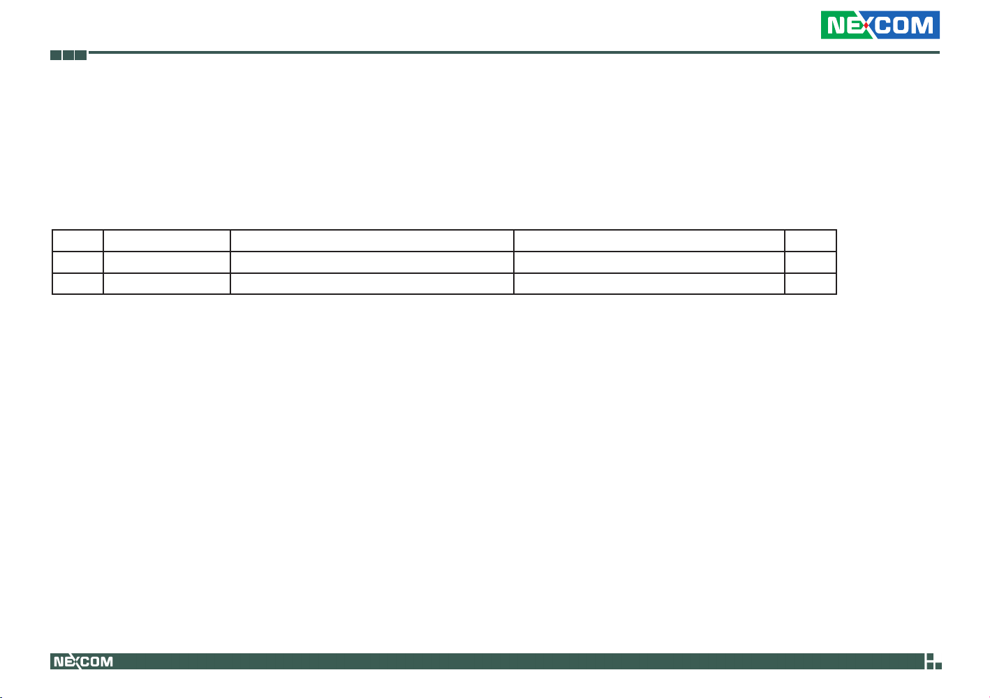
Package contents
Before continuing, verify that the NEX 880/890 package that you received is complete. Your package should have all the items listed in the following table.
Item Part Number Name Description Qty
1 50222A0468X00 NEX880 I/O PANEL VER:A NORTHERN QUEEN 158.75x44.45x4.40mm SUS t=0.2mm 1
2 60233ATA17X00 SATA CABLE BEST:148-0707-300R Standard L:300mm 1
Copyright © 2011 NEXCOM International Co., Ltd. All Rights Reserved.
xii
NEX 880/890 User Manual

Preface
ordering information
The following provides ordering information for NEX 880 and NEX 890.
• NEX880(P/N:10G00088000X0)RoHSCompliant
microATX, LGA1155, 2nd generation Intel® Core™ Desktop processors, Q67, DDR3 DIMM x4, VGA, DVI-D, 2x GbE, PCIe x8, PCIe x4, 2x PCIe x1,
2x RS232
• NEX890(P/N:10G00089000X0)RoHSCompliant
microATX, LGA1155, 2nd generation Intel® Core™ Workstation processors, C206, DDR3 DIMM x4, VGA, DVI-D, 2x GbE, PCIe x8, PCIe x4, 2x PCIe x1,
2x RS232
Copyright © 2011 NEXCOM International Co., Ltd. All Rights Reserved.
xiii
NEX 880/890 User Manual

Chapter 1: Product Introduction
Chapter 1: produCt IntroduCtIon
Overview
Key Features
®
• 2nd generation Intel
2nd generation Intel
Core™ Desktop processors (NEX 880)
®
Core™ Workstation processors (NEX 890)
• 4x DDR3 DIMM up to 32GB (NEX 890 supports ECC)
• Dual display: VGA and DVI
• 2x Intel
• Supports Intel
®
Gigabit Ethernet LAN
®
AMT 7.0
• SATA 3.0
• 2x RS232
Copyright © 2011 NEXCOM International Co., Ltd. All Rights Reserved.
• NEX 880
1x PCIe x16 (with PCIe x8 signals), 1x PCIe x8 (with PCIe x1
signals), 1x PCIe x4, 1x PCIe x4 (with PCIe x1 signals)
• NEX 890
1x PCIe x16 (with PCIe x8 signals), 1x PCIe x8, 2x PCIe x4
1
NEX 880/890 User Manual

Chapter 1: Product Introduction
Hardware Specifications
CPU
• LGA 1155, 2nd generation Intel® Core™ Desktop processors (NEX 880)
LGA 1155, 2nd generation Intel® Core™ Workstation processors (NEX 890)
Chipset
• Intel® Q67 Platform Controller Hub (NEX 880)
Intel® C206 Platform Controller Hub (NEX 890)
Main Memory
• 4x 240-pin DDR3 DIMM sockets
• Supports up to 32GB 1066/1333 dual channel DIMM
• Supports non-ECC unbuffered DIMM (NEX 880)
Supports ECC DIMM (NEX 890)
Onboard LAN
• 1x Intel® 82579LM PHY for AMT 7.0
• 1x Intel® 82583 PCI Express Gigabit Ethernet
• Supports boot from LAN (PXE)
• 2x RJ45 with LED
Display
• 2nd generation Intel® Core™ Desktop processors
• Integrated HD graphics
• 1x VGA
• 1x DVI-D
Expansion
• NEX 880
1x PCIe x16 (with PCIe x8 signals) slot
1x PCIe x8 (with PCIe x1 signals) slot
1x PCIe x4 (with PCIe x1 signals) slot
1x PCIe x4 with PCIe x4 signals) slot
• NEX 890
1x PCIe x16 (with PCIe x8 signals) slot
1x PCIe x8 slot
2x PCIe x4 slots
Edge I/O Interfaces
• 1x dual stack mini DIN 6-pin connector for PS2 KB/MS
• 1x dual stack DB9 male connector for COM1 & COM2
• 1x DVI + DB15 female connector for VGA
• 2x RJ45 with dual stack USB connectors
• Line-In/Line-Out/Mic phone jack
Copyright © 2011 NEXCOM International Co., Ltd. All Rights Reserved.
2
NEX 880/890 User Manual

Chapter 1: Product Introduction
I/O Interfaces
• USB 2.0: 10 ports (6 onboard pin headers, 4 with type A connector for
external)
• Serial port: 2 ports, with 2x5 pin headers (COM 1 and COM 2)
• SATA HDD: 6 ports, port 1, 2 support SATA 3.0, port 3, 4, 5, 6 support
SATA 2.0
• Supports RAID 0/1/5/10 and Intel® Matrix Storage
• IrDA: onboard pin header
• GPIO: Supports 4 sets general purpose I/O each with TTL level (5 V)
interface
• 1x onboard buzzer
• Power LED/Power On/Reset/HDD LED pin header
• 1x 4-pin fan connector (for CPU); 2x 3-pin fan connectors (for System)
• On-chip RTC with battery backup
• 1x External Li-lon battery
BIOS
• AMI BIOS
• Plug and play support
System Monitor
• 4 Voltages (+3.3V, +5V, +12V, Vcore)
• 2 Temperatures (For CPU and System)
• 3 FAN speed monitors (1 for CPU and 2 for System FAN)
Power Input
• Supports ATX power supply
• Standard ATX 24-pin connector for +12V/ +5V/ +3.3V/ +5Vsb/ -12V
• ATX 8-pin connector for +12V
Dimensions
• microATX
• 244mm (L) x 244mm (W)
Environment
• Board level operating temperatures: 0°C to 60°C
• Storage temperature: -20°C to 85°C
• Relative humidity: 10% to 90%, (Non-condensing)
Certifications
• CE approval
• FCC Class A
Copyright © 2011 NEXCOM International Co., Ltd. All Rights Reserved.
3
NEX 880/890 User Manual
Chapter 1: Product Introduction
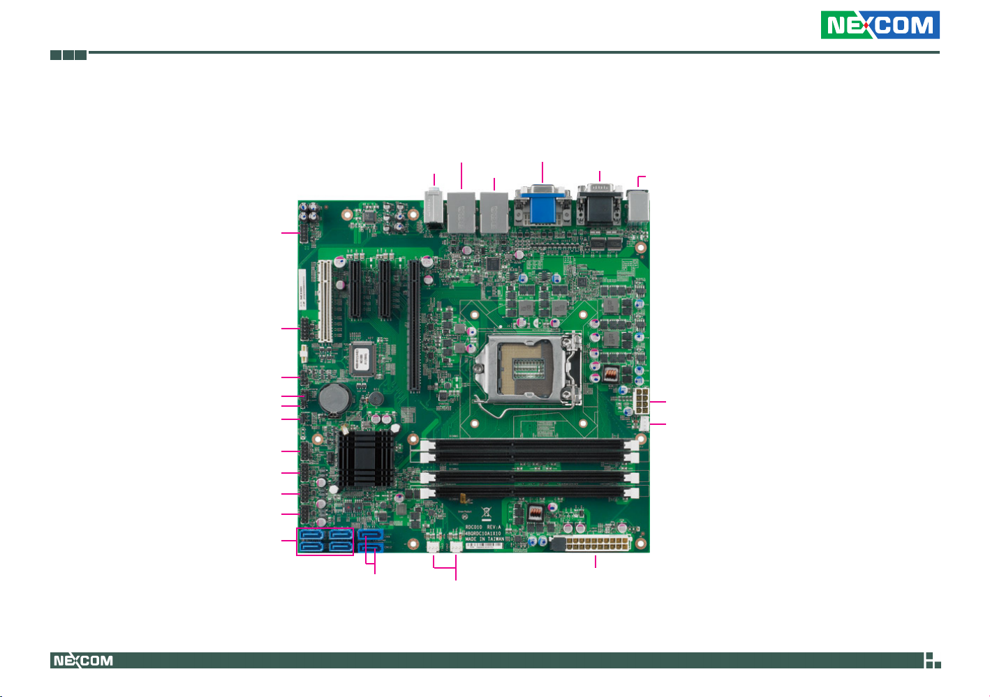
Getting to Know NEX 880/890
FP Audio
GPIO
SMBus
ME Clear
CMOS Clear
FP Control
USB1
USB2
USB3
SATA 2.0
USB/LAN
Line-in/Line-out/Mic-in
IR
USB/LAN
DVI/VGA
COM1/COM2
PS/2 KB/MS
ATX Power
CPU Fan
Copyright © 2011 NEXCOM International Co., Ltd. All Rights Reserved.
SATA 3.0
System Fan
ATX Power
4
NEX 880/890 User Manual

Chapter 2: Jumpers and Connectors
Chapter 2: Jumpers and ConneCtors
This chapter describes how to set the jumpers and connectors on the NEX
880/890 motherboard.
Before You Begin
• Ensure you have a stable, clean working environment. Dust and dirt can
get into components and cause a malfunction. Use containers to keep
small components separated.
• Adequate lighting and proper tools can prevent you from accidentally
damaging the internal components. Most of the procedures that follow
require only a few simple tools, including the following:
• A Philips screwdriver
• A flat-tipped screwdriver
• A set of jewelers Screwdrivers
• A grounding strap
• An anti-static pad
• Using your fingers can disconnect most of the connections. It is recom-
mended that you do not use needle-nosed pliers to disconnect connections as these can damage the soft metal or plastic parts of the connectors.
• Before working on internal components, make sure that the power
is off. Ground yourself before touching any internal components, by
touching a metal object. Static electricity can damage many of the elec-
tronic components. Humid environment tend to have less static electricity than dry environments. A grounding strap is warranted whenever
danger of static electricity exists.
Precautions
Computer components and electronic circuit boards can be damaged by
discharges of static electricity. Working on the computers that are still connected to a power supply can be extremely dangerous.
Follow the guidelines below to avoid damage to your computer or yourself:
• Always disconnect the unit from the power outlet whenever you are
working inside the case.
• If possible, wear a grounded wrist strap when you are working inside
the computer case. Alternatively, discharge any static electricity by
touching the bare metal chassis of the unit case, or the bare metal body
of any other grounded appliance.
• Hold electronic circuit boards by the edges only. Do not touch the com-com-
ponents on the board unless it is necessary to do so. Don’t flex or stress
the circuit board.
• Leave all components inside the static-proof packaging that they
shipped with until they are ready for installation.
• Use correct screws and do not over tighten screws.
Copyright © 2011 NEXCOM International Co., Ltd. All Rights Reserved.
5
NEX 880/890 User Manual
 Loading...