


NEXCOM International Co., Ltd.
Multi-Media Solutions
Digital Signage Platform
NDiS 126
User Manual
NEXCOM International Co., Ltd. |
www.nexcom.com |
|
Published March 2014 |
||
|
||
|
|

Contents
Contents
Preface |
|
Copyright .............................................................................................. |
iv |
Disclaimer .............................................................................................. |
iv |
Acknowledgements ............................................................................... |
iv |
Regulatory Compliance Statements ....................................................... |
iv |
Safety Information ................................................................................. |
vii |
Package Contents |
|
Ordering Information |
|
Chapter 1: Product Introduction |
|
Overview................................................................................................. |
1 |
Key Features............................................................................................ |
1 |
Physical Features...................................................................................... |
2 |
Hardware Specifications........................................................................... |
3 |
System.................................................................................................... |
3 |
Main Board............................................................................................. |
5 |
Mechanical Dimensions (NDiS126)........................................................... |
7 |
Mechanical Dimensions (NDiS126-V)....................................................... |
8 |
Mechanical Dimensions (NDiS126-H)....................................................... |
9 |
Chapter 2: Jumpers and Connectors |
|
Before You Begin .................................................................................. |
10 |
Precautions ........................................................................................... |
11 |
Jumper Settings..................................................................................... |
12 |
Locations of the Jumpers and Connectors.............................................. |
13 |
External Connectors Pin Definitions....................................................... |
14 |
Power Input Connector..................................................................... |
14 |
ATX Power Switch............................................................................. |
14 |
LAN Connector................................................................................. |
15 |
USB Port........................................................................................... |
15 |
HDMI Connector............................................................................... |
16 |
SIM Card Slot.................................................................................... |
16 |
LED HDD/PWR ................................................................................. |
17 |
RS232 Port........................................................................................ |
17 |
Internal Connectors Pin Definitions........................................................ |
18 |
Serial-ATA Connector........................................................................ |
18 |
Serial-ATA Power Connector............................................................. |
18 |
USB Connector................................................................................. |
19 |
Serial-ATA DOM Power..................................................................... |
19 |
Mini-PCIe.......................................................................................... |
20 |
RTC Battery Connector..................................................................... |
21 |
RTC Clear Jump................................................................................ |
21 |
IR Connector..................................................................................... |
21 |
System Reset..................................................................................... |
21 |
System Temp Sensor......................................................................... |
22 |
Copyright © 2011 NEXCOM International Co., Ltd. All Rights Reserved. |
ii |
NDiS 126 User Manual

Contents
|
|
|
|
|
|
|
|
Intel IGD Configuration |
52 |
|
|
|
|
|
.................................................................................................GPIO |
22 |
|
|
|
||||||
|
|
NTK-AV Board Connector................................................................. |
23 |
IDE Configuration.................................................................................. |
53 |
|
|
|
||||
NTK-AV01 / NTK-AV02 Connectors Pin Definitions................................. |
24 |
Intel Fast Flash Standby.......................................................................... |
54 |
|
|
|
||||||
|
|
PCIE 4x 64pin Connector.................................................................. |
24 |
USB Configuration................................................................................. |
55 |
|
|
|
||||
|
|
VGA Connector (NTK-AV01)............................................................. |
25 |
Super IO Configuration ......................................................................... |
56 |
|
|
|
||||
|
|
HDMI Connector (NTK-AV02)............................................................ |
25 |
H/W Monitor......................................................................................... |
57 |
|
|
|
||||
|
|
Audio Line Out Connector (NTK-AV01 / NTK-AV02).......................... |
26 |
PPM Configuration................................................................................ |
58 |
|
|
|
||||
|
|
Audio Line In Connector (NTK-AV01)................................................ |
26 |
Boot ..................................................................................................... |
59 |
|
|
|
||||
|
|
Mic-in Pin Header (NTK-AV02).......................................................... |
26 |
Security................................................................................................. |
60 |
|
|
|
||||
Chapter 3: System Setup |
|
Save & Exit............................................................................................ |
61 |
|
|
|
||||||
|
Appendix A: Watchdog Timer |
|
|
|
|
|||||||
Removing the Chassis Cover.................................................................. |
27 |
|
|
|
|
|||||||
Installing a DIMM.................................................................................. |
28 |
Appendix B: GPI/O Programming Guide |
|
|
|
|
||||||
Installing a SATA Hard Drive................................................................... |
30 |
|
|
|
|
|||||||
Installing a Wireless LAN Module........................................................... |
34 |
|
|
|
|
|
||||||
Installing a TV Tuner Module.................................................................. |
38 |
|
|
|
|
|
||||||
Installing Wallmount Brackets................................................................ |
42 |
|
|
|
|
|
||||||
Chapter 4: BIOS Setup |
|
|
|
|
|
|
||||||
About BIOS Setup.................................................................................. |
43 |
|
|
|
|
|
||||||
When to Configure the BIOS................................................................. |
43 |
|
|
|
|
|
||||||
Default Configuration ........................................................................... |
44 |
|
|
|
|
|
||||||
Entering Setup....................................................................................... |
44 |
|
|
|
|
|
||||||
Legends................................................................................................. |
44 |
|
|
|
|
|
||||||
Scroll Bar .............................................................................................. |
45 |
|
|
|
|
|
||||||
BIOS Setup Utility.................................................................................. |
45 |
|
|
|
|
|
||||||
Main .................................................................................................... |
46 |
|
|
|
|
|
||||||
Advanced.............................................................................................. |
47 |
|
|
|
|
|
||||||
ACPI Settings......................................................................................... |
49 |
|
|
|
|
|
||||||
RTC Wake Settings................................................................................ |
50 |
|
|
|
|
|
||||||
CPU Configuration................................................................................ |
51 |
|
|
|
|
|
||||||
|
|
|
|
|
|
|
|
|
|
|
|
|
|
|
|
|
|
|
|
|
|
|
|
|
|
|
|
|
|
|
|
|
|
|
|
|
|
|
|
|
|
|
|
|
|
|
|
|
|
|
|
Copyright © 2011 NEXCOM International Co., Ltd. All Rights Reserved. |
iii |
NDiS 126 User Manual

Preface
Preface
Copyright
This publication, including all photographs, illustrations and software, is protected under international copyright laws, with all rights reserved. No part of this manual may be reproduced, copied, translated or transmitted in any form or by any means without the prior written consent from NEXCOM International Co., Ltd.
Disclaimer
The information in this document is subject to change without prior notice and does not represent commitment from NEXCOM International Co., Ltd. However, users may update their knowledge of any product in use by constantly checking its manual posted on our website: http://www.nexcom. com. NEXCOM shall not be liable for direct, indirect, special, incidental, or consequential damages arising out of the use of any product, nor for any infringements upon the rights of third parties, which may result from such use. Any implied warranties of merchantability or fitness for any particular purpose is also disclaimed.
Acknowledgements
NDiS 126 is a trademark of NEXCOM International Co., Ltd. All other product names mentioned herein are registered trademarks of their respective owners.
Regulatory Compliance Statements
This section provides the FCC compliance statement for Class A devices and describes how to keep the system CE compliant.
Declaration of Conformity
FCC
This equipment has been tested and verified to comply with the limits for a Class A digital device, pursuant to Part 15 of FCC Rules. These limits are designed to provide reasonable protection against harmful interference when the equipment is operated in a commercial environment. This equipment generates, uses, and can radiate radio frequency energy and, if not installed and used in accordance with the instructions, may cause harmful interference to radio communications. Operation of this equipment in a residential area (domestic environment) is likely to cause harmful interference, in which case the user will be required to correct the interference (take adequate measures) at their own expense.
CE
The product(s) described in this manual complies with all applicable European Union (CE) directives if it has a CE marking. For computer systems to remain CE compliant, only CE-compliant parts may be used. Maintaining CE compliance also requires proper cable and cabling techniques.
Copyright © 2011 NEXCOM International Co., Ltd. All Rights Reserved. |
iv |
NDiS 126 User Manual

Preface
RoHS Compliance
NEXCOM RoHS Environmental Policy and Status Update
NEXCOM is a global citizen for building the digital infrastructure. We are committed to providing green products and services, which are compliant with Euro-
pean Union RoHS (Restriction on Use of Hazardous Substance in Electronic Equipment) directive 2002/95/EU, to be your trusted green partner and to protect our environment.
RoHS restricts the use of Lead (Pb) < 0.1% or 1,000ppm, Mercury (Hg)
<0.1% or 1,000ppm, Cadmium (Cd) < 0.01% or 100ppm, Hexavalent Chromium (Cr6+) < 0.1% or 1,000ppm, Polybrominated biphenyls (PBB)
<0.1% or 1,000ppm, and Polybrominated diphenyl Ethers (PBDE) < 0.1% or 1,000ppm.
In order to meet the RoHS compliant directives, NEXCOM has established an engineering and manufacturing task force in to implement the introduction of green products. The task force will ensure that we follow the standard NEXCOM development procedure and that all the new RoHS components and new manufacturing processes maintain the highest industry quality levels for which NEXCOM are renowned.
The model selection criteria will be based on market demand. Vendors and suppliers will ensure that all designed components will be RoHS compliant.
How to recognize NEXCOM RoHS Products?
For existing products where there are non-RoHS and RoHS versions, the suffix “(LF)” will be added to the compliant product name.
All new product models launched after January 2006 will be RoHS compliant. They will use the usual NEXCOM naming convention.
Copyright © 2011 NEXCOM International Co., Ltd. All Rights Reserved. |
v |
NDiS 126 User Manual

Preface
Warranty and RMA
NEXCOM Warranty Period
NEXCOM manufactures products that are new or equivalent to new in accordance with industry standard. NEXCOM warrants that products will be free from defect in material and workmanship for 2 years, beginning on the date of invoice by NEXCOM. HCP series products (Blade Server) which are manufactured by NEXCOM are covered by a three year warranty period.
NEXCOM Return Merchandise Authorization (RMA)
?? Customers shall enclose the “NEXCOM RMA Service Form” with the returned packages.
?? Customers must collect all the information about the problems encountered and note anything abnormal or, print out any on-screen messages, and describe the problems on the “NEXCOM RMA Service Form” for the RMA number apply process.
?? Customers can send back the faulty products with or without accessories (manuals, cable, etc.) and any components from the card, such as CPU and RAM. If the components were suspected as part of the problems, please note clearly which components are included. Otherwise, NEXCOM is not responsible for the devices/parts.
?? Customers are responsible for the safe packaging of defective products, making sure it is durable enough to be resistant against further damage and deterioration during transportation. In case of damages occurred during transportation, the repair is treated as “Out of Warranty.”
?? Any products returned by NEXCOM to other locations besides the customers’ site will bear an extra charge and will be billed to the customer.
Repair Service Charges for Out-of-Warranty Products
NEXCOM will charge for out-of-warranty products in two categories, one is basic diagnostic fee and another is component (product) fee.
System Level
?? Component fee: NEXCOM will only charge for main components such as SMD chip, BGA chip, etc. Passive components will be repaired for free, ex: resistor, capacitor.
?? Items will be replaced with NEXCOM products if the original one cannot be repaired. Ex: motherboard, power supply, etc.
?? Replace with 3rd party products if needed.
?? If RMA goods can not be repaired, NEXCOM will return it to the customer without any charge.
Board Level
?? Component fee: NEXCOM will only charge for main components, such as SMD chip, BGA chip, etc. Passive components will be repaired for free, ex: resistors, capacitors.
?? If RMA goods can not be repaired, NEXCOM will return it to the customer without any charge.
Copyright © 2011 NEXCOM International Co., Ltd. All Rights Reserved. |
vi |
NDiS 126 User Manual

Preface
Warnings
Read and adhere to all warnings, cautions, and notices in this guide and the documentation supplied with the chassis, power supply, and accessory modules. If the instructions for the chassis and power supply are inconsistent with these instructions or the instructions for accessory modules, contact the supplier to find out how you can ensure that your computer meets safety and regulatory requirements.
Cautions
Electrostatic discharge (ESD) can damage system components. Do the described procedures only at an ESD workstation. If no such station is available, you can provide some ESD protection by wearing an antistatic wrist strap and attaching it to a metal part of the computer chassis.
Safety Information
Before installing and using the device, note the following precautions: ▪▪ Read all instructions carefully.
▪▪ Do not place the unit on an unstable surface, cart, or stand. ▪▪ Follow all warnings and cautions in this manual.
▪▪ When replacing parts, ensure that your service technician uses parts specified by the manufacturer.
▪▪ Avoid using the system near water, in direct sunlight, or near a heating device.
▪▪ The load of the system unit does not solely rely for support from the rackmounts located on the sides. Firm support from the bottom is highly necessary in order to provide balance stability.
▪▪ The computer is provided with a battery-powered real-time clock circuit. There is a danger of explosion if battery is incorrectly replaced. Replace only with the same or equivalent type recommended by the manufacturer. Discard used batteries according to the manufacturer’s instructions.
Installation Recommendations
Ensure you have a stable, clean working environment. Dust and dirt can get into components and cause a malfunction. Use containers to keep small components separated.
Adequate lighting and proper tools can prevent you from accidentally damaging the internal components. Most of the procedures that follow require only a few simple tools, including the following:
•A Philips screwdriver
•A flat-tipped screwdriver
•A grounding strap
•An anti-static pad
Using your fingers can disconnect most of the connections. It is recommended that you do not use needlenose pliers to disconnect connections as these can damage the soft metal or plastic parts of the connectors.
Copyright © 2011 NEXCOM International Co., Ltd. All Rights Reserved. |
vii |
NDiS 126 User Manual

Preface
Safety Precautions
1.Read these safety instructions carefully.
2.Keep this User Manual for later reference.
3.Disconnect this equipment from any AC outlet before cleaning. Use a damp cloth. Do not use liquid or spray detergents for cleaning.
4.For plug-in equipment, the power outlet socket must be located near the equipment and must be easily accessible.
5.Keep this equipment away from humidity.
6.Put this equipment on a stable surface during installation. Dropping it or letting it fall may cause damage.
7.Do not leave this equipment in either an unconditioned environment or in a above 40oC storage temperature as this may damage the equipment.
8.The openings on the enclosure are for air convection to protect the equipment from overheating. DO NOT COVER THE OPENINGS.
9.Make sure the voltage of the power source is correct before connecting the equipment to the power outlet.
10.Place the power cord in a way so that people will not step on it. Do not place anything on top of the power cord. Use a power cord that has been approved for use with the product and that it matches the voltage and current marked on the product’s electrical range label.
The voltage and current rating of the cord must be greater than the voltage and current rating marked on the product.
11.All cautions and warnings on the equipment should be noted.
12.If the equipment is not used for a long time, disconnect it from the power source to avoid damage by transient overvoltage.
13.Never pour any liquid into an opening. This may cause fire or electrical shock.
14.Never open the equipment. For safety reasons, the equipment should be opened only by qualified service personnel.
15.If one of the following situations arises, get the equipment checked by service personnel:
a.The power cord or plug is damaged.
b.Liquid has penetrated into the equipment.
c.The equipment has been exposed to moisture.
d.The equipment does not work well, or you cannot get it to work according to the user’s manual.
e.The equipment has been dropped and damaged.
f.The equipment has obvious signs of breakage.
16.Do not place heavy objects on the equipment.
17.The unit uses a three-wire ground cable which is equipped with a third pin to ground the unit and prevent electric shock. Do not defeat the purpose of this pin. If your outlet does not support this kind of plug, contact your electrician to replace your obsolete outlet.
18.CAUTION: DANGER OF EXPLOSION IF BATTERY IS INCORRECTLY REPLACED. REPLACE ONLY WITH THE SAME OR EQUIVALENT TYPE RECOMMENDED BY THE MANUFACTURER. DISCARD USED BATTERIES ACCORDING TO THE MANUFACTURER’S INSTRUCTIONS.
19.The computer is provided with CD drives that comply with the appropriate safety standards including IEC 60825.
Copyright © 2011 NEXCOM International Co., Ltd. All Rights Reserved. |
viii |
NDiS 126 User Manual
Preface
Technical Support and Assistance
1.For the most updated information of NEXCOM products, visit NEXCOM’s website at www.nexcom.com.
2.For technical issues that require contacting our technical support team or sales representative, please have the following information ready before calling:
–Product name and serial number
–Detailed information of the peripheral devices
–Detailed information of the installed software (operating system, version, application software, etc.)
–A complete description of the problem
–The exact wordings of the error messages
Warning!
1.Handling the unit: carry the unit with both hands and handle it with care.
2.Maintenance: to keep the unit clean, use only approved cleaning products or clean with a dry cloth.
3.CompactFlash: Turn off the unit’s power before inserting or removing a CompactFlash storage card.
Conventions Used in this Manual
Warning: Information about certain situations, which if not observed, can cause personal injury. This will prevent injury to yourself when performing a task.
Caution: Information to avoid damaging components or losing data.
Note: Provides additional information to complete a task easily.
Copyright © 2011 NEXCOM International Co., Ltd. All Rights Reserved. |
ix |
NDiS 126 User Manual

Preface
Global Service Contact Information
Headquarters
NEXCOM International Co., Ltd.
15F, No. 920, Chung-Cheng Rd., Zhonghe District, New Taipei City, 23586, Taiwan, R.O.C.
Tel: +886-2-8226-7786
Fax: +886-2-8226-7782 www.nexcom.com
America
USA NEXCOM USA
2883 Bayview Drive, Fremont CA 94538, USA Tel: +1-510-656-2248 Fax: +1-510-656-2158 Email: sales@nexcom.com www.nexcom.com
Asia
Taiwan
Central Taiwan Office
16F, No.250, Sec. 2, Chongde Rd., Beitun Dist., Taichung City 406, R.O.C. Tel: +886-4-2249-1179
Fax: +886-4-2249-1172 Email: sales@nexcom.com.tw www.nexcom.com.tw
Japan NEXCOM Japan
9F, Tamachi Hara Bldg., 4-11-5, Shiba Minato-ku, Tokyo, 108-0014, Japan Tel: +81-3-5419-7830 Fax: +81-3-5419-7832
Email: sales@nexcom-jp.com www.nexcom-jp.com
China NEXCOM China
2F, Block 4, Venus Plaza, Bldg. 21, ZhongGuanCun Software Park, No. 8, Dongbeiwang West Rd., Haidian District, Beijing, 100193, China
Tel: +86-10-8282-6599
Fax: +86-10-8282-5955 Email: sales@nexcom.cn www.nexcom.cn
Shanghai Office
Room 603/604, Huiyinmingzun Plaza Bldg., 1, No.609, Yunlin East Rd.,
Shanghai, 200062, China
Tel: +86-21-5278-5868
Fax: +86-21-3251-6358 Email: sales@nexcom.cn www.nexcom.cn
Copyright © 2011 NEXCOM International Co., Ltd. All Rights Reserved. |
x |
NDiS 126 User Manual
Preface
Shenzhen Office
Room1707, North Block, Pines Bldg., No.7 Tairan Rd., Futian Area, Shenzhen, 518040, China
Tel: +86-755-8332-7203
Fax: +86-755-8332-7213 Email: sales@nexcom.cn www.nexcom.cn
Wuhan Office
1-C1804/1805, Mingze Liwan, No. 519 South Luoshi Rd., Hongshan District,
Wuhan, 430070, China Tel: +86-27-8722-7400 Fax: +86-27-8722-7400 Email: sales@nexcom.cn www.nexcom.cn
Chengdu Office
9F, Shuxiangxie, Xuefu Garden, No.12 Section 1, South Yihuan Rd., Chengdu, 610061, China
Tel: +86-28-8523-0186
Fax: +86-28-8523-0186 Email: sales@nexcom.cn www.nexcom.cn
Copyright © 2011 NEXCOM International Co., Ltd. All Rights Reserved.
Europe
Italy
NEXCOM ITALIA S.r.l
Via Gaudenzio Ferrari 29, 21047 Saronno (VA), Italia Tel: +39 02 9628 0333 Fax: +39 02 9286 9215
Email: nexcomitalia@nexcom.eu www.nexcomitalia.it
United Kingdom
NEXCOM EUROPE
10 Vincent Avenue, Crownhill Business Centre,
Milton Keynes, Buckinghamshire, MK8 0AB, United Kingdom
Tel: +44-1908-267121
Fax: +44-1908-262042 Email: sales.uk@nexcom.eu www.nexcom.eu
xi
NDiS 126 User Manual

Preface
Package Contents
Before continuing, verify that the NDiS 126 package that you received is complete. Your NDiS 126 package should have all the items listed in the following table.
Item |
P/N |
Name |
Specification |
Qty |
|
|
|
|
1 |
50311F0119X00 |
I HEAD BOLTS SCREW LONG FEI:I3*12.5ISO NIGP |
I3x12.5 AXISx8.5mm SCREWx4mm |
4 |
|
|
|
|
|
|
|
|
|
|
|
|
|
2 |
5044440031X00 |
RUBBER FOOT KANG YANG:RF20-5-4P |
19.8x18x5.0mm |
4 |
|
|
|
|
|
|
|
|
|
|
|
|
|
3 |
601111A156X00 |
CARTON FOR NDiS126 YI GIA |
316x212x120mm(INSIDE) B FLUTE |
1 |
|
|
|
|
4 |
6012200049X00 |
ASG110 PE BAG 24x38cm |
240x380x0.08mm |
1 |
|
|
|
|
|
|
|
|
|
|
|
|
|
5 |
6012200052X00 |
PE ZIPPER BAG #8 |
170x240mm,W/China RoHS SYMBOL |
1 |
|
|
|
|
|
|
|
|
|
|
|
|
|
6 |
6012200053X00 |
PE ZIPPER BAG #3 |
100x70mm,W/China RoHS SYMBOL |
1 |
|
|
|
|
|
|
|
|
|
|
|
|
|
7 |
6013300311X00 |
EPE FOR NDiS126 SENTENEL |
316x212x74mm |
2 |
|
|
|
|
|
|
|
|
|
|
|
|
|
8 |
60233ATA13X00 |
SATA CABLE 90° TO 180° BEST:109-0707-070R |
L:70mm 90° TO 180° CONNECTOR |
1 |
|
|
|
|
9 |
60233PW197X00 |
SATA POWER CABLE BEST:900-0415-070R |
FEMALE CONNCTOR 15P TO HOUSING 4P |
1 |
|
|
|
|
|
|
|
PIT:2.54mm L:70mm |
|
|
|
|
|
10 |
602DCD0430X00 |
NDiS126 CD DRIVER MANUAL VER:1.0 |
JCL |
1 |
|
|
|
|
|
|
|
|
|
|
|
|
|
11 |
7400050001X00 |
POWER ADAPTER L.T.E.:LTE50E-S2-208 |
50W 12V/4.17A |
1 |
|
|
|
|
|
|
|
|
|
|
|
|
|
|
|
|
|
|
|
|
|
|
|
|
|
|
|
|
|
|
|
|
|
|
|
|
|
|
|
|
|
|
|
|
|
|
|
|
|
Copyright © 2011 NEXCOM International Co., Ltd. All Rights Reserved. |
xii |
NDiS 126 User Manual

Preface
Ordering Information
The following provides ordering information for NDiS 126.
•NDiS 126 (P/N: 10W00012600X0)
-Intel® Atom™ processor D2700
-Intel® NM10 Express chipset
•NDiS 126V (P/N: 10W00126V00X0)
-Intel® Atom™ processor D2700
-Intel® NM10 Express chipset
-Additional VGA output
•NDiS 126H (P/N: 10W00126H00X0)
-Intel® Atom™ processor D2700
-Intel® NM10 Express chipset
-Additional HDMI output
Copyright © 2011 NEXCOM International Co., Ltd. All Rights Reserved. |
xiii |
NDiS 126 User Manual

Chapter 1: Product Introduction
Chapter 1: Product Introduction
Overview |
Key Features |
|
|
|
|
▪▪ Intel® Atom™ processor D2700 |
|
|
|
|
▪▪ Low power consumption |
|
|
|
|
▪▪ Compact and fanless |
|
|
|
|
▪▪ Dual GbE LAN |
|
|
|
|
▪▪ Hyper-threading support |
|
|
|
|
▪▪ IntelR GMA 3650 integrated graphic engine |
|
|
|
|
▪▪ Compact and Fan-Less Design |
|
|
|
Powered by Intel® Atom™ processor D2700, NDiS 126 has enhanced |
|
|
|
|
graphics capabilities to playback HD video with low power consumption. |
|
|
|
|
NDiS 126provides various options of video and audio outputs, dual GbE |
|
|
|
|
Ethernet with optional wireless connectivity, SIM Card slot for 3.5G radio |
|
|
|
|
connectivity. |
|
|
|
|
Compact and fanless design makes the NDiS 126 an ideal choice for digital |
|
|
|
|
signage platforms adapted to almost any environment. NDiS 126 works |
|
|
|
|
perfectly for advertising, brand promotion and digital menu board |
|
|
|
|
application. |
|
|
|
|
|
|
|
|
|
|
|
|
|
|
|
|
|
|
|
|
|
|
|
|
Copyright © 2011 NEXCOM International Co., Ltd. All Rights Reserved. |
1 |
NDiS 126 User Manual |
Chapter 1: Product Introduction
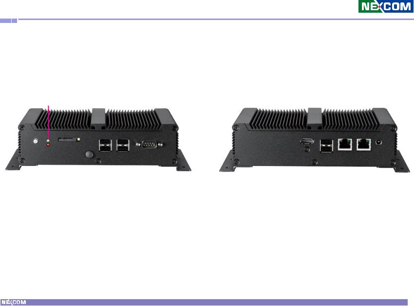
Physical Features
Front panel |
Rear panel |
Power
LED
|
|
|
|
|
|
|
|
|
|
|
|
|
|
|
|
|
|
|
|
|
|
|
|
|
|
|
|
|
|
|
|
|
|
|
|
|
|
|
|
|
|
|
|
|
|
|
|
|
|
|
|
|
|
|
|
|
|
|
|
|
|
|
|
|
|
|
|
|
|
|
|
|
|
|
|
|
|
|
|
|
|
|
|
|
|
|
|
|
|
|
|
|
|
|
|
|
|
|
|
|
|
|
|
|
|
|
|
|
|
|
|
|
|
Power |
HDD SIM Card |
USB |
COM |
HDMI USB |
LAN 12V DC-in |
|
|
|
||||||||||
|
|
|
|
|
|
|
||||||||||||
Button |
LED Slot |
|
|
|
|
|
|
|
||||||||||
|
|
|
|
|
|
|
|
|
|
|
|
|
|
|||||
|
|
|
|
|
|
|
|
|
|
|
|
|
|
|
|
|
|
|
|
|
|
|
|
|
|
|
|
|
|
|
|
|
|
|
|
|
|
|
|
|
|
|
|
|
|
|
|
|
|
|
|
|
|
|
|
|
|
|
|
|
|
|
|
|
|
|
|
|
|
|
|
|
|
|
|
Copyright © 2011 NEXCOM International Co., Ltd. All Rights Reserved. |
2 |
NDiS 126 User Manual |

Chapter 1: Product Introduction
Hardware Specifications
System
Processor
▪▪ Intel® Atom™ processor D2700 2.16GHz onboard
Chipset
▪▪ Intel® NM10 Express chipset
Main Memory
▪▪ One 200pin SO-DIMM socket, support
▪▪ DDR3 800/1067MHz SO-DIMM SDRAM with un-buffered and Non-ECC memory module
▪▪ Support up to 4GB memory
Graphics
▪▪ Graphics chip
-Intel® GMA 3650 integrated graphic engine
-Intel® Dynamic Video Memory Technology
-Image Rotate by driver support
▪▪ HDMI
Integrated HDMI (iHDMI)
-Video support for CEA modes 480i/p, 576i/p, 720p, 1080i/p and PC modes though dot clock
-Intel® HD Audio support
-Integrated Intel® HD Audio codec
-Dolby* AC3 compress, Dolby* Digital, Dolby* DTS (full support)
-PCM audio support
▪▪ Dual Display (Additional)
-Dual independent display: HDMI+VGA
-Dual independent display: HDMI+HDMI
|
3 |
|
|
|
|
|
|
|
|
|
|
|
|
|
|
|
|
Copyright © 2011 NEXCOM International Co., Ltd. All Rights Reserved. |
NDiS 126 User Manual |
||||

Chapter 1: Product Introduction
Network
▪▪ 2 x Intel® WG82583V GbE controller
▪▪ PXE LAN boot ROM for Ethernet Boot up. ▪▪ Support WOL
▪▪ 2 x RJ45 connector with LAN speed and Link/active LEDs
Storage
▪▪ One 2.5” HDD Bracket
▪▪ One 7-pin SATA connector
▪▪ One 2-pin power connector for SATA DOM ▪▪ One 4-Pin power connector for SATA HDD
Audio
▪▪ ALC 886-GR HD codec
▪▪ HDMI for PCM audio output
I/O Interfaces
▪▪ Serial
-DB9 COM 1 (RS232) connector at the front panel ▪▪ USB
-USB 2.0 ports 1~2 at the rear panel
-USB 2.0 ports 3~6 at the front panel
-USB 2.0 Port 7 reserved, JST
-USB 2.0 Port 8 to mini-PCIe
▪▪ GPIO
-8 GPIO lines (GPI 0~3 and GPO 0~3); TTL Level (0/5V)
-2x5 pin header, 2.54mm
▪▪ SIM Slot
-1 x External accessible SIM card slot for WWAN ▪▪ Others
-OnBoard buzzer
-RTC reset: 1x3 pin header, 2.54mm
-IR interface: 1x5 pin header, 2.54mm
-Reset: 1x2 pin header, 2.54mm
|
4 |
|
|
|
|
|
|
|
|
|
|
|
|
|
|
|
|
Copyright © 2011 NEXCOM International Co., Ltd. All Rights Reserved. |
NDiS 126 User Manual |
||||

Chapter 1: Product Introduction
Power Supply
▪▪ Onboard DC to DC
-Power range design: +12V +/-10% DC input
-2.5mm DC-In power jack
-ATX power mode
-Supports wake up alarm
-Supports WOL
-Support power on after failure
-Support soft off
▪▪ External adapter
- +12V DC output 50W
RTC Battery
▪▪ On chip RTC with battery back up / One External Li-ion Battery ▪▪ RTC tolerance less than 2sec (24 hours) under 25°C environment
BIOS
▪▪ AMI system BIOS
▪▪ 16Mbits SPI flash ROM
System Management
▪▪ Monitoring
-Super IO built-in function (IT8783)
-Monitoring of 4 voltages, 3 temperature 4 voltage (For +3.3V, +5V, +12V, Vcore)
3 Temperatures (CPU, RAM, external Temperature Sensor)
▪▪ Watchdog
-Watchdog timeout is programmable by software from 1 second to 255 seconds and from 1 minute to 255 minutes
-Tolerance: 15% under room temperature 25°C
Operating System Support
▪▪ Microsoft Windows 7 / WES7
Main Board
External I/O
▪▪ Front I/O
-Power Button
-Power LED (Green)
-HDD LED (Red)
-1 x External accessible SIM card slot
-1 x SMA type antenna hole
-1 x RS232 COM port
-4 x USB 2.0 ports
|
5 |
|
|
|
|
|
|
|
|
|
|
|
|
|
|
|
|
Copyright © 2011 NEXCOM International Co., Ltd. All Rights Reserved. |
NDiS 126 User Manual |
||||

Chapter 1: Product Introduction
▪▪ Rear I/O
-1 x HDMI port
-2 x USB 2.0 ports
-2 x RJ45 Gigabit LAN ports
-+12V DC-in jack
Physical Characteristics
▪▪ Dimensions (W x D x H)
-185mm (W) x 147mm (D) x 48.4mm (H)
-(7.3”x 5.8”x 1.9”) w/o wall mount bracket
▪▪ Color
- Black
▪▪ Mounting
-Wall mount bracket
-VESA 75x75 / 100x100 mounting bracket
▪▪ Cooling system - Fanless
Expansion
▪▪ One Mini-PCIe slots
▪▪ Supports Wireless LAN module & DVB-T TV-tuner module ▪▪ Support wake on WLAN feature
▪▪ Additional at AV I/O expansion
-NTK-AV01: 1 x VGA port + 1 x Line out port + 1 x Line in port
-NTK-AV02: 1 x HDMI port + 1x Line out port
Environment
▪▪ Operating temperature: 100% CPU loading and component thermal profile: 0 ~ 40 °C
▪▪ Storage temperature: -40°C ~ 80°C
▪▪ Relative humidity (non-condensing): 95%
Certificate
▪▪ CE
▪▪ FCC Class A
|
6 |
|
|
|
|
|
|
|
|
|
|
|
|
|
|
|
|
Copyright © 2011 NEXCOM International Co., Ltd. All Rights Reserved. |
NDiS 126 User Manual |
||||

Chapter 1: Product Introduction
Mechanical Dimensions (NDiS126)
147
185
215.4
48.4 55
|
7 |
|
|
|
|
|
|
|
|
|
|
|
|
|
|
|
|
Copyright © 2011 NEXCOM International Co., Ltd. All Rights Reserved. |
NDiS 126 User Manual |
||||

Chapter 1: Product Introduction
Mechanical Dimensions (NDiS126-V)
147
185
215.4
48.4 55
|
8 |
|
|
|
|
|
|
|
|
|
|
|
|
|
|
|
|
Copyright © 2011 NEXCOM International Co., Ltd. All Rights Reserved. |
NDiS 126 User Manual |
||||

Chapter 1: Product Introduction
Mechanical Dimensions (NDiS126-H)
147
185
215.4
48.4 55
|
9 |
|
|
|
|
|
|
|
|
|
|
|
|
|
|
|
|
Copyright © 2011 NEXCOM International Co., Ltd. All Rights Reserved. |
NDiS 126 User Manual |
||||

Chapter 2: Jumpers and Connectors
Chapter 2: Jumpers and Connectors
This chapter describes how to set the jumpers on the motherboard. Note that the following procedures are generic for all NDiS 126 series.
Before You Begin
▪▪ Ensure you have a stable, clean working environment. Dust and dirt can get into components and cause a malfunction. Use containers to keep small components separated.
▪▪ Adequate lighting and proper tools can prevent you from accidentally damaging the internal components. Most of the procedures that follow require only a few simple tools, including the following:
-- A Philips screwdriver
-- A flat-tipped screwdriver
-- A set of jewelers Screwdrivers -- A grounding strap
-- An anti-static pad
▪▪ Using your fingers can disconnect most of the connections. It is recommended that you do not use needle-nosed pliers to disconnect connections as these can damage the soft metal or plastic parts of the connectors.
▪▪ Before working on internal components, make sure that the poweris off. Ground yourself before touching any internal components, by touching a metal object. Static electricity can damage many of the electronic components. Humid environment tend to have less static electricity
▪▪ than dry environments. A grounding strap is warranted whenever danger of static electricity exists.
|
10 |
|
|
|
|
|
|
|
|
|
|
|
|
|
|
|
|
Copyright © 2011 NEXCOM International Co., Ltd. All Rights Reserved. |
NDiS 126 User Manual |
||||

Chapter 2: Jumpers and Connectors
Precautions
Computer components and electronic circuit boards can be damaged by discharges of static electricity. Working on the computers that are still connected to a power supply can be extremely dangerous.
Follow the guidelines below to avoid damage to your computer or yourself:
▪▪ Always disconnect the unit from the power outlet whenever you are working inside the case.
▪▪ If possible, wear a grounded wrist strap when you are working inside the computer case. Alternatively, discharge any static electricity by touching the bare metal chassis of the unit case, or the bare metal body of any other grounded appliance.
▪▪ Hold electronic circuit boards by the edges only. Do not touch the components on the board unless it is necessary to do so. Don’t flex or stress the circuit board.
▪▪ Leave all components inside the static-proof packaging that they shipped with until they are ready for installation.
▪▪ Use correct screws and do not over tighten screws.
|
11 |
|
|
|
|
|
|
|
|
|
|
|
|
|
|
|
|
Copyright © 2011 NEXCOM International Co., Ltd. All Rights Reserved. |
NDiS 126 User Manual |
||||
 Loading...