

Page 1
Reference Manual for the Double 108 Mbps Wireless Firewall Router WGU624
NETGEAR, Inc.
4500 Great America Parkway
Santa Clara, CA 95054 USA
M-10153-01
Version 1.1
September 2004
M-10153-01
Page 2

© 2004 by NETGEAR, Inc. All rights reserved.
Trademarks
NETGEAR is a trademark of Netgear, Inc.
Microsoft, Windows, and Wi ndow s NT are registered trademar ks of Microsoft Corporation.
Other brand and product names are registered trademarks or trademarks of their respective holders.
Statement of Conditions
In the interest of improving internal design, operational function, and/or reliability, NETGEAR reserves the right to
make changes to the products described in this document without notice.
NETGEAR does not assume any liability that may occur due to the use or application of the product(s) or circuit
layout(s) described herein.
Federal Communications Commission (FCC) Compliance Notice: Radio Frequency Notice
This equipment has been tested and found to comply with the limits for a Class B digital device, pursuant to
part 15 of the FCC Rules. These limits are designed to provide reasonable protection against harmful interference in a
residential installation. This equipment generates, uses, and can radiate radio frequency energy and, if not installed and
used in accordance with the instruct ions, may cause harmf ul interference to radio communications. However, there is no
guarantee that interference will not occur in a particular installation. If this equipment does cause harmful interference to
radio or television reception, which can be determined by turning the equipment off and on, the user is encouraged to try
to correct the interference by one or more of the following measures:
• Reorient or relocate the receiving antenna.
• Increase the separation between the equipment and receiver.
• Connect the equipment into an outlet on a circuit different from that to which the receiver is connected.
• Consult the dealer or an experienced radio/TV technician for help.
FCC Caution
1. FCC RF Radiation Exposure Statement: The equipment complies with FCC RF radiation exposure limits set forth
for an uncontrolled environment. This equipment should be installed and operated with a minimum distance of 20
centimeters between the radiator and your body .
2. This Transmitter must not be co-located or operating in conjunction with any other antenna or transmitter.
3. Changes or modifications to this unit not expressly approved by the party responsible for compliance could void the
user authority to operate the equipment.
2
M-10153-01
Page 3
Europe - EU Declaration of Conformity
This device is a 2.4/5.0 GHz dual band low power RF
device intended for home and office use in EU and
EFTA member states. In some EU / EFTA member
states some restrictions may apply. Please contact
local spectrum management authorities for further
details before putting this device into operation.
Marking by the above symbol indicates compliance with the Essential Requirements of the R&TTE Directive of the
European Union (1999/5/EC). This equipment meets the following conformance standards:
EN 300 328, EN 301 489-17, EN 60950-1 Safety of Information Technology Eq uipment, In cluding Electrical Business
Equipment EN 300 328 V1.4.1 (2003-04) Electromagnetic compatibility and Radio spectrum Matters (ERM); Wi deband
Transmission system; data transmission equipment operating in the 2.4 Ghz ISM band and using spread spectrum
modulation techniques; Part 1: T echnical characteristics and test conditions; Part 2; Harmonized EN covering essential
requirements under article 3.2 of the R&TTE Directive.
EN 301 489-1, Aug. 2002; EN 301 489-17, Aug. 2002 - Electromagnetic compatibility and radio spectrum matters
(ERM); electromagnetic compatibility (EMC); standard for radio equipment and services: Part 1: Common technical
requirements; Part 17: Specific conditions for Wideband Data and Hiperlan equipment.
EN 55 022 Declaration of Conformance
This is to certify that the Double 108 Mbps Wireless Firewall Router WGU624 is shielded against the generation of
radio interference in accordance with the application of Council Directive 89/336/EEC, Article 4a. Conformity is
declared by the application of EN 55 022 Class B (CISPR 22).
Compliance with the applicable regulations is dependent upon the use of shielded cables. It is the responsibility of the
user to procure the appropriate cables.
Requirements For Operation in the European Community
Countries of Operation and Conditions of Use in the European Community
The user should run the configuration utility program provided with this product to check the current channel of
operation and confirm that the device is operating in conformance with the spectrum usage rules for European
Community countries as described in this section. European standards dictate a maximum radiated transmit power of
100mW EIRP and a frequency range of 2.400 - 2.4835 Ghz.
Operation Using 2.4 GHz Channels in France
The following radio channel usage limitations apply in France.
The radio spectrum regulator in France, Autorité de regulation des telecommunications (ART), enforces the following
rules with respect to use of 2.4GHz spectrum in various locations in France. Please check ART's Web site for latest
M-10153-01
3
Page 4

requirements for use of the 2.4GHz band in France: http://www. art-telecom.fr/eng/ind ex.htm. When operating in France,
this device may be operated under the following conditions:
Indoors only, using any channel in the 2.4465-2.4835 GHz band.
Bestätigung des Herstellers/Importeurs
Es wird hiermit bestätigt, daß das Double 108 Mbps Wireless Firewall Router WGU624 gemäß der im
BMPT-AmtsblVfg 243/1991 und Vfg 46/1992 aufgeführten Bestimmungen entstört ist. Das vorschriftsmäßige
Betreiben einiger Geräte (z.B. Testsender) kann jedoch gewissen Beschränkungen unterliegen. Lesen Sie dazu bitte die
Anmerkungen in der Betriebsanleitung.
Das Bundesamt für Zulassungen in der Telekommunikation wurde davon unterrichtet, daß dieses Gerät auf den Markt
gebracht wurde und es ist berechtigt, die Serie auf die Erfüllung der Vorschriften hin zu überprüfen.
Certificate of the Manufacturer/Importer
It is hereby certified that the Double 108 Mbps Wireless Firewall Router WGU624 has been suppressed in accordance
with the conditions set out in the BMPT-AmtsblVfg 243/1991 and Vfg 46/1992. The operation of some equipment (for
example, test transmitters) in accordance with the regulations may, however, be subject to certain restrictions. Please
refer to the notes in the operating instructions.
Federal Office for Telecommunications Approvals has been notified of the placing of this equipment on the market
and has been granted the right to test the series for compliance with the regulations.
Voluntary Control Council for Interference (VCCI) Statement
This equipment is in the second category (information equipment to be used in a residential area or an adjacent area
thereto) and conforms to the standards set by the Voluntary Control Council for Interference by Data Processing
Equipment and Electronic Office Machines aimed at preventing radio interference in such residential areas.
When used near a radio or TV receiver , it may become the cause of radio interference.
Read instructions for correct handling.
Customer Support
Refer to the Support Information Card that shipped with your Double 108 Mbps Wireless Firewall Router WGU624.
World Wide Web
NETGEAR maintains a World Wide Web home page that you can access at the universal resource locator (URL)
http://www.netgear.com. A direct connection to the Internet and a Web browser such as Internet Explorer
or Netscape are required.
4
M-10153-01
Page 5

Contents
Chapter 1
About This Manual
Audience, Scope, Conventions, and Formats ................................................................1-1
How to Use This Manual ................................................................................................1-2
How to Print this Manual .................................................................................................1-3
Chapter 2
Introduction
Key Features of the Router ............................................................................................2-1
802.11 a/g Wireless Networking ...............................................................................2-2
Comparing the 802.11a, 802.11b, and 802.11g Modes ..................................................2-2
A Powerful, True Firewall with Content Filtering ......................................................2-3
Security ....................................................................................................................2-4
Autosensing Ethernet Connections with Auto Uplink ...............................................2-4
Extensive Protocol Support ......................................................................................2-5
Easy Installation and Management ..........................................................................2-5
Maintenance and Support .................. .... ... ... ... .......................................... ... .... ... ... ..2-6
Package Contents ..........................................................................................................2-6
The Router’s Front Panel .........................................................................................2-7
The Router’s Rear Panel .........................................................................................2-8
Chapter 3
Connecting the Router to the Internet
What You Will Need Before You Begin .................................. .... ... ..................................3-1
Cabling and Computer Hardware Requirements .....................................................3-1
Computer Network Configuration Requirements ............................. ... ... ... ... .... ... .....3-1
Internet Configuration Requirements ....................................................................... 3-2
Where Do I Get the Internet Configuration Parameters? ............................. ............3-2
Record Your Internet Connection Information ..........................................................3-3
Connecting the WGU624 ....................... ... .... ... ... ... ... .... ... ... ... .... .....................................3-4
Connecting the Wireless Router ............................ ... ... ... .... ... ... ... .... ........................3-4
Contents 1
M-10153-01
Page 6

How to Manually Configure Your Internet Connection ........ .......................................... ..3-9
Manual PPPoE Configuration ................................................................................3-11
Manual PPTP Configuration ...................................................................................3-13
Manual Telstra Bigpond Configuration ...................................................................3-15
Chapter 4
Wireless Configuration
Observing Performance, Placement, and Range Guidelines .........................................4-1
Implementing Appropriate Wireless Security ..................................................................4-2
Wireless Mode Options ................... .......................................... ... ... ... ............................4-3
Default Basic Wireless Settings ...............................................................................4-4
Basic 802.11a Wireless Settings ..............................................................................4-4
Basic 802.11g Wireless Settings ..............................................................................4-6
Wireless Security Settings ........................ .... ... ... ... ... .... ... .......................................... ... ..4-9
WEP Authentication and Encryption ......................................................... ... .... ... ... ..4-9
Security Mode Selection ..................................................................................4-10
Cipher Type Choices .......................................................................................4-10
WPA Encryption .....................................................................................................4-11
Recording Your SSID and Security Settings .................................................................4-13
Setting Up and Testing Basic Wireless Connectivity ....................................................4-14
Restricting Wireless Access by MAC Address ....................... ................................ 4-15
Configuring WEP ....................................................................................................4-17
Configuring WPA-PSK Encryption Security ...........................................................4-18
Configuring Advanced Wireless Settings .....................................................................4-19
Default Advanced Wireless Settings ......................................................................4-19
Configuring Advanced 802.11a Wireless Settings .................................................4-20
Configuring Advanced 802.11b/g Wireless Settings ..............................................4-21
Chapter 5
Content Filtering
Blocking Access to Internet Sites ...................................................................................5-1
Blocking Access to Internet Services .............................................................................5-3
Scheduling When Blocking Will Be Enforced .................................................................5-5
Viewing Logs of Web Access or Attempted Web Access ...............................................5-6
Configuring E-Mail Alert and Web Access Log Notifications ..........................................5-8
2 Contents
M-10153-01
Page 7

Chapter 6
Maintenance
Viewing Wireless Router Status Information ...................................................................6-1
Viewing a List of Attached Devices .................................................................................6-5
Upgrading the Router Software ......................................................................................6-5
Configuration File Management .....................................................................................6-7
Restoring and Backing Up the Configuration ...........................................................6-7
Erasing the Configuration .........................................................................................6-8
Changing the Administrator Password ...........................................................................6-8
Chapter 7
Advanced Configuration
Comparison of Port Triggering and Port Forwarding ...................................................... 7-1
Configuring Port Forwarding ...........................................................................................7-2
Adding a Port Forwarding Custom Service ..............................................................7-3
Local Web and FTP Server Example .......................................................................7-4
Configuring Port Triggering .............................................................................................7-5
Configuring WAN Setup Options ....................................................................................7-6
Configuring LAN IP Setup Options .................................................................................7-8
Using the Router as a DHCP Server ......................................................................7-10
Using Address Reservation ....................................................................................7-11
Using a Dynamic DNS Service .....................................................................................7-12
Configuring Static Routes .............................................................................................7-13
Enabling Remote Management Access .......................................................................7-16
Using Universal Plug and Play (UPnP) ........................................................................7-17
Chapter 8
Troubleshooting
Basic Functioning ...........................................................................................................8-1
Power LED Not On ...................................................................................................8-2
LEDs Never Turn Off ................................................................................................8-2
Local or Internet Port LEDs Not On ................ ... .... ... ... ... .... ... ... ...............................8-2
Troubleshooting the Web Configuration Interface ..........................................................8-3
Troubleshooting the ISP Connection ..............................................................................8-4
Troubleshooting a TCP/IP Network Using a Ping Utility .................................................8-5
Testing the LAN Path to the WGU624 ......................................................................8-5
Testing the Path from Your PC to a Remote Device ................................................8-6
Contents 3
M-10153-01
Page 8

Restoring the Default Configuration and Password ............... .........................................8-7
Problems with Date and Time .........................................................................................8-7
Why Does the WGU624 Not Reach Full 108 Mbps Speeds? .........................................8-8
Appendix A
Technical Specifications
Appendix B
Network, Routing, Firewall, and Basics
Related Publications ...................................................................................................... B-1
Basic Router Concepts .................................................................................................. B-1
What is a Router? ................................................................................................... B-1
Routing Information Protocol ................................................................................... B-2
IP Addresses and the Internet .. ... .... ... ... ... .... ................................................................. B-2
Netmask .................................... ................................................................ ..............B-4
Subnet Addressing .................................................................................................. B-5
Private IP Addresses ................................. ... ... ... .......................................... ........... B-7
Single IP Address Operation Using NAT ....................................................................... B-8
MAC Addresses and Address Resolution Protocol ................................................. B-9
Related Documents ................................................................................................. B-9
Domain Name Server ............................................................................................ B-10
IP Configuration by DHCP ...................................................................... ... ... ... ... ......... B-10
Internet Security and Firewalls .................................................................................... B-10
What is a Firewall? .................................................................................................B-11
Stateful Packet Inspection .................................. ... ... .... ... ... ... .... ... ... ................B-11
Denial of Service Attack ..................................................................................B-11
Ethernet Cabling ................................. ... ... .... ... .......................................... ... ... ... .... ... ...B-11
Category 5 Cable Quality ...................................................................................... B-12
Inside Twisted Pair Cables .................................................................................... B-13
Uplink Switches, Crossover Cables, and MDI/MDIX Switching ............................ B-14
Appendix C
Preparing Your Network
Preparing Your Computers for TCP/IP Networking ................................................... ... . C-1
Configuring Windows 95, 98, and Me for TCP/IP Networking ....................................... C-2
Install or V erify Windows Networking Components ................................................. C-2
Enabling DHCP to Automatically Configure TCP/IP Settings .................................C-4
Selecting Windows’ Internet Access Method .......................................................... C-6
4 Contents
M-10153-01
Page 9

Verifying TCP/IP Properties .................................................................................... C-6
Configuring Windows NT4, 2000 or XP for IP Networking ............................................C-7
Install or V erify Windows Networking Components ................................................. C-7
DHCP Configuration of TCP/IP in Windows XP, 2000, or NT4 ...............................C-8
DHCP Configuration of TCP/IP in Windows XP ..................................................... C-8
DHCP Configuration of TCP/IP in Windows 2000 ................................................ C-10
DHCP Configuration of TCP/IP in Windows NT4 .................................................. C-13
Verifying TCP/IP Properties for Windows XP, 2000, and NT4 .............................. C-15
Configuring the Macintosh for TCP/IP Networking ...................................................... C-16
MacOS 8.6 or 9.x ................................................................ .................................. C-16
MacOS X ...... ... .......................................... .......................................... ..................C-17
Verifying TCP/IP Properties for Macintosh Computers ... .... ... ... ... .... ... ... ... ... .... .....C-17
Verifying the Readiness of Your Internet Account ....................................................... C-18
Are Login Protocols Used? ................................................................................... C-18
What Is Your Configuration Information? .............................................................. C-18
Obtaining ISP Configuration Information for Windows Computers .......................C-19
Obtaining ISP Configuration Information for Macintosh Computers .....................C-20
Restarting the Network ................................................................................................C-21
Appendix D
Wireless Networking Basics
Wireless Networking Overview .............................. ... .... ... ... ... .... ... ... ... .... ... ... ... ... .... ... ....D-1
Infrastructure Mode .................................................................................................D-1
Ad Hoc Mode (Peer-to-Peer Workgroup) ................................................................ D-2
Network Name: Extended Service Set Identification (ESSID) ................................D-2
Authentication and WEP ........................... .... ... ... ... ... .... ... ... ... .... ... ... .............................. D-3
802.11 Authentication ..............................................................................................D-3
Open System Authentication .............................. .... ... ... ... .... ... ... ... .... ....................... D-4
Shared Key Authentication ......................................................................................D-4
Overview of WEP Parameters ................................................................................ D-5
Key Size .................................................................................................................. D-6
WEP Configuration Options ......................... ... ... .......................................... .... ... ... . D-7
Wireless Channels ....................... .... ... ... ... ..................................................................... D-7
WPA Wireless Security ..................................................................................................D-8
How Does WPA Compare to WEP? ........................................................................ D-9
How Does WPA Compare to IEEE 802.11i? ........................................................ D-10
Contents 5
M-10153-01
Page 10

What are the Key Features of WPA Security? ...................................................... D-10
WPA Authentication: Enterprise-level User
Authentication via 802.1x/EAP and RADIUS ..................................................D-12
WPA Data Encryption Key Management ........................................................D-14
Is WPA Perfect? ........................................... ... .......................................... ............D-16
Product Support for WPA ......................................................................................D-16
Supporting a Mixture of WPA and WEP Wireless Clients is Discouraged ......D-16
Changes to Wireless Access Points ............................................................... D-17
Changes to Wireless Network Adapters .........................................................D-17
Changes to Wireless Client Programs .......................... ......................... ......... D-18
Glossary
List of Glossary Terms ...................................................................................................G-1
Index
6 Contents
M-10153-01
Page 11
Chapter 1
About This Manual
This chapter describes the intended audience, scope, conventions, and formats of this manual.
Audience, Scope, Conventions, and Formats
This reference manual assumes that the reader has basic to intermediate computer and Internet
skills. However, basic computer network, Internet, firewall, and VPN technologies tutorial
information is provided in the Appendices and on the Netgear website.
This guide uses the following typographical conventions:
Table 1-1. Typographical Conventions
italics Emphasis, books, CDs, URL names
bold User input
courier font Screen text, file and server names, extensions, commands, IP addresses
This guide uses the following formats to highlight special messages:
Note: This format is used to highlight information of importance or special interest.
This manual is written for the WGU624 wireless router according to these specifications.:
Table 1-2. Manual Scope
Product Version Double 108 Mbps Wireless Firewall Router WGU624
Manual Publication Date September 2004
Note: Product updates are available on the NETGEAR, Inc. Web site at
http://kbserver.netgear.com/products/WGU624.asp.
About This Manual 1
M-10153-01
Page 12
Reference Manual for the Double 108 Mbps Wireless Firewall Router WGU624
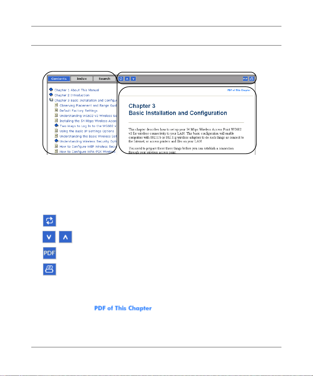
How to Use This Manual
The HTML version of this manual includes a variety of navigation features as well as links to PDF
versions of the full manual and individual chapters.
1
2
3
Figure 1 -1: HTML version of this manual
1. Left pane. Use the left pane to view the Contents, Index, Search, and Favorites tabs.
To view the HTML version of the manual, you must have a version 4 or later browser with
JavaScript enabled.
2. Toolbar buttons . Use the toolbar buttons across the top to navigate, print pages, an d more.
The Show in Contents button locates the current topic in the Contents tab.
Previous/Next buttons display the previous or next topic.
The PDF button links to a PDF version of the full manual.
The Print button prints the current topic. Using this button when a
step-by-step procedure is displayed will send the entire procedure to your
printer--you do not have to worry about specifying the correct range of pages.
3. Right pane. Use the right pane to view the contents of the manual. Also, each page of the
manual includes a link at the top right which links to a PDF file
containing just the currently selected chapter of the manual.
2 About This Manual
M-10153-01
Page 13
Reference Manual for the Double 108 Mbps Wireless Firewall Router WGU624
How to Print this Manual
To print this manual you man choose one of the following several options, according to your
needs.
• Printing a “How To” Sequence of Steps in the HTML View. Use the Print button on
the upper right of the toolbar to print the currently displayed topic. Using this button when a
step-by-step procedure is displayed will send the entire procedure to your printer--you do not
have to worry about specifying the correct range of pages.
• Printing a Chapter. Use the link at the top right of any page.
– Click “PDF of This Chapter” link at the top right of any page in the chapter you want to
print. The PDF version of the chapter you were viewing opens in a browser window.
Note: Your computer must have the free Adobe Acrobat reader installed in order to view
and print PDF files. The Acrobat reader is available on the Adobe Web site at
http://www.adobe.com.
– Click the print icon in the upper left of the window.
Tip: If your printer supports printing two pages on a single sheet of paper, you can save
paper an printer ink by selecting this feature.
• Printing the Full Manual. Use the PDF button in the toolbar at the top right of the browser
window.
– Click the PDF button on the upper right of the toolbar. The PDF version of the
chapter you were viewing opens in a browser window.
– Click the print icon in the upper left of the window.
Tip: If your printer supports printing two pages on a single sheet of paper, you can save
paper an printer ink by selecting this feature.
About This Manual 3
M-10153-01
Page 14

Reference Manual for the Double 108 Mbps Wireless Firewall Router WGU624
4 About This Manual
M-10153-01
Page 15

Chapter 2
Introduction
Congratulations on your purchase of the NETGEAR® Double 108 Mbps Wireless Firewall Router
WGU624. The WGU624 wireless router provides connection for multiple personal computers
(PCs) to the Internet through an external broadband access device (such as a cable modem or DSL
modem) that is normally intended for use by a single PC. This chapter describes the features of the
NETGEAR Double 108 Mbps Wireless Firewall Router WGU624.
Key Features of the Router
The Double 108 Mbps Wireless Firewall Router WGU624 with 4-port switch conne cts your local
area network (LAN) to the Internet through an external access device such as a cable modem or
DSL modem.
The WGU624 wireless router provides you with multiple Web content filtering options, plus
browsing activity reporting and instant alerts — both via e-mail. Parents and network
administrators can establish restricted access policies based on time of day, Web site addresses and
address keywords, and share high-speed cable/DSL Internet access for up to 253 personal
computers. In addition to the Network Address Translation (NAT) feature, the built-in firewall
protects you from hackers.
With minimum setup, you can install and use the router within minutes.
The WGU624 wireless router provides the following features:
• 802.11g wireless networking, with the ability to operate in 802.11g-only, 802.11-turbo-g-only,
or 802.11b+g modes.
• 802.11a wireless networking
• Channel bonding combines the bandwidth of two radio channels into one commun ications link
(54 Mbps +54 Mbps =108 Mbps) between the router and wireless stations
• Super A and Super G modes
• Easy, Web-based setup for installation and management.
• Content Filtering and Site Blocking Security.
Introduction 2-1
M-10153-01
Page 16

Reference Manual for the Double 108 Mbps Wireless Firewall Router WGU624
• Built-in 4-port 10/100 Mbps Switch.
• LAN port 4 is a built-in hardware DMZ port
• Ethernet connection to a wide area network (WAN) device, such as a cable modem or DSL
modem.
• Extensive protocol support.
• Login capability
• Front panel LEDs for easy monitoring of status and activity.
• Flash memory for firmware upgrades.
802.11 a/g Wireless Networking
The WGU624 wireless router includes 802.11 a and 802.11g wireless access points, providing
continuous, high-speed access between your wireless and Ethernet devices. The router provides:
• 802.11g and 802.11a wireless networking at up to 108 Mbps.
• 802.11g wireless networking, with the ability to operate in 802.11g-only, 802.11-turbo-g-only,
or 802.11b+g modes, providing backwards compatibility with 802.11b devices or dedicating
the wireless network to the higher bandwidth 802.11g devices.
• 802.11a wireless networking, with the ability to operate in 802.11a-only, 108 Mbps only, or
Auto 108 Mbps modes.
• When Super G Modes is enabled, the wireless router will enable channel bonding, data
compression, packet bursting and large frame support. Channel bonding takes two of the three
usable channels in 2.4GHz 802.11b/g and uses them to double the speed.
• 64-, 128-, and 152-bit WEP encryption security.
• WEP keys can be generated manually or by passphrase.
• WPA and WPA-PSK wireless security.
• Wireless access can be restricted by MAC address.
• Wireless network name broadcast can be turned off so that only devices that have the network
name (SSID) can connect.
Comparing the 802.11a, 802.11b, and 802.11g Modes
The Double 108 Mbps Wireless Firewall Router WGU624 offers a variety of wireless modes. The
table below compares some of the features of each mode.
2-2 Introduction
M-10153-01
Page 17

Reference Manual for the Double 108 Mbps Wireless Firewall Router WGU624
Table 2-1. Comparison of Wireless Modes
Features 802.11b 802.11a Super A 802.11g Super G
Performance 11 Mbps 54 Mbps 108 Mbps 54 Mbps 108 Mbps
Range In practice,
about 100 feet
indoors. Up to
1500 feet in the
open.
Compatibility 802.11b only Only with
Channel Any Any Any Any 6
Frequency 2.4 GHz 5 GHz 5 GHz 2.4 GHz 2.4 GHz
Less than “b” More than “a” Two times “b” Four times “b”
normal 802.11a
802.11a 802.11g and
802.11b
(Can use a “g”
router with a “b”
adapter.)
802.11g and
802.11b
A Powerful, True Firewall with Content Filtering
Unlike simple Internet sharing NAT routers, the WGU624 is a true firewall, using stateful packet
inspection to defend against hacker attacks. Its firewall features include:
• Denial of Service (DoS) protection.
Automatically detects and thwarts DoS attacks such as Ping of Death, SYN Flood, LAND
Attack, and IP Spoofing.
• Blocks unwanted traffic from the Internet to your LAN.
• Blocks access from your LAN to Internet locations or services that you specify as off-limits.
• Logs security incidents.
The WGU624 will log security events such as blocked incoming traffic, port scans, attacks,
and administrator logins. You can configure the router to e-mail the log to you at specified
intervals. You can also configure the router to send immediate alert messages to your e-mail
address or e-mail pager whenever a significant event occurs.
• The WGU624 prevents objectionable content from reaching your PCs. The router allows you
to control access to Internet content by screening for keywords within W eb addresses. You can
configure the router to log and report attempts to access objectionable Internet sites.
Introduction 2-3
M-10153-01
Page 18

Reference Manual for the Double 108 Mbps Wireless Firewall Router WGU624
Security
The WGU624 wireless router is equipped with several features designed to maintain security, as
described in this section.
• PCs Hidden by NAT
NAT opens a temporary path to the Internet for requests originating from the local network.
Requests originating from outside the LAN are discarded, preventing users outside the LAN
from finding and directly accessing the PCs on the LAN.
• DMZ Hardware Port
A Demilitarized Zone (DMZ) is used by a company that wants to host its own Internet services
without sacrificing unauthorized access to its private network.
The DMZ sits between the Internet and an internal network's line of defense, usually some
combination of firewalls and bastion hosts. Typically, the DMZ contains devices accessible to
Internet traffic, such as Web (HTTP) servers, FTP servers, SMTP (e-mail) servers and DNS
servers.
• Port Forwarding with NAT
Although NAT prevents Internet locations from directly accessing the PCs on the LAN, the
router allows you to direct incoming traffic to specific PCs based on the service port number
of the incoming request, or to one designated “DMZ” host computer. You can specify
forwarding of single ports or ranges of ports.
Autosensing Ethernet Connections with Auto Uplink
With its internal 8-port 10/100 switch, the WGU624 can connect to either a 10 Mbps standard
Ethernet network or a 100 Mbps Fast Ethernet network. Both the LAN and WAN interfaces are
autosensing and capable of full-duplex or half-duplex operation.
TM
The router incorporates Auto Uplink
whether the Ethernet cable plugged into the port should have a ‘normal’ connection such as to a
PC or an ‘uplink’ connection such as to a switch or hub. That port then configures itself to the
correct configuration. This feature also eliminates the need to worry about crossover cables, as
Auto Uplink accommodates either type of cable to make the right connection.
2-4 Introduction
technology. Each Ethernet port automatically senses
M-10153-01
Page 19

Reference Manual for the Double 108 Mbps Wireless Firewall Router WGU624
Extensive Protocol Support
The WGU624 wireless router supports the Transmission Control Protocol/Internet Protocol
(TCP/IP) and Routing Information Protocol (RIP). For further information about TCP/IP, refer to
Appendix B, “Network, Routing, Firewall, and Basics”.
• IP Address Sharing by NAT
The WGU624 wireless router allows several networked PCs to share an Internet account using
only a single IP address, which may be statically or dynamically assigned by your Internet
service provider (ISP). This technique, known as NAT, allows the use of an inexpensive
single-user ISP account.
• Automatic Configuration of Attached PCs by DHCP
The WGU624 wireless router dynamically assigns network configuration information,
including IP, gateway, and domain name server (DNS) addresses, to attached PCs on the LAN
using the Dynamic Host Configuration Protocol (DHCP). This feature greatly simplifies
configuration of PCs on your local network.
• DNS Proxy
When DHCP is enabled and no DNS addresses are specified, the router provides its own
address as a DNS server to the attached PCs. The router obtains actual DNS addresses from
the ISP during connection setup and forwards DNS requests from the LAN.
• PPP over Ethernet (PPPoE)
PPPoE is a protocol for connecting remote hosts to the Internet over a DSL connection by
simulating a dial-up connection. This feature eliminates the need to run a login program such
as Entersys or WinPOET on your PC.
Easy Installation and Management
You can install, configure, and operate the Double 108 Mbps Wireless Firewall Router WGU624
within minutes after connecting it to the network. The following features simplify installation and
management tasks:
• Browser-based management
Browser-based configuration allows you to easily configure your router from almost any type
of personal computer, such as Windows, Macintosh, or Linux. A user-friendly Setup Wizard is
provided and online help documentation is built into the browser-based Web Management
Interface.
• Smart Wizard
The WGU624 wireless router Smart Wizard automatically senses the type of Internet
connection, asking you only for the information required for your type of ISP account.
Introduction 2-5
M-10153-01
Page 20

Reference Manual for the Double 108 Mbps Wireless Firewall Router WGU624
• Firmware Auto-Update
The WGU624 wireless router automatically checks the Internet to see if a newer version of
firmware is available. If so, it asks if you want to install the upgrade. This lets you take
advantage of product enhancements for your WGU624 as soon as they become available.
• Visual monitoring
The WGU624 wireless router’s front panel LEDs provide an easy way to monitor its status
and activity.
Maintenance and Support
NETGEAR offers the following features to help you maximize your use of the WGU624 wireless
router:
• Flash memory for firmware upgrades
• Free technical support seven days a week, twenty-four hours a day
Package Contents
The product package should contain the following items:
• Double 108 Mbps Wireless Firewall Router WGU624.
•AC power adapter.
• Vertical stand.
• Category 5 (CAT5) Ethernet cable.
• Double 108 Mbps Wireless Router WGU624 Resource CD , including:
—The Setup Manual for the WGU624.
— Application Notes and other helpful information.
• Installation Guide for the WGU624.
• Registration and Warranty Card.
• Support Information Card.
If any of the parts are incorrect, missing, or damaged, contact your NETGEAR dealer. Keep the
carton, including the original packing materials, in case you need to return the router for repair.
2-6 Introduction
M-10153-01
Page 21
Reference Manual for the Double 108 Mbps Wireless Firewall Router WGU624
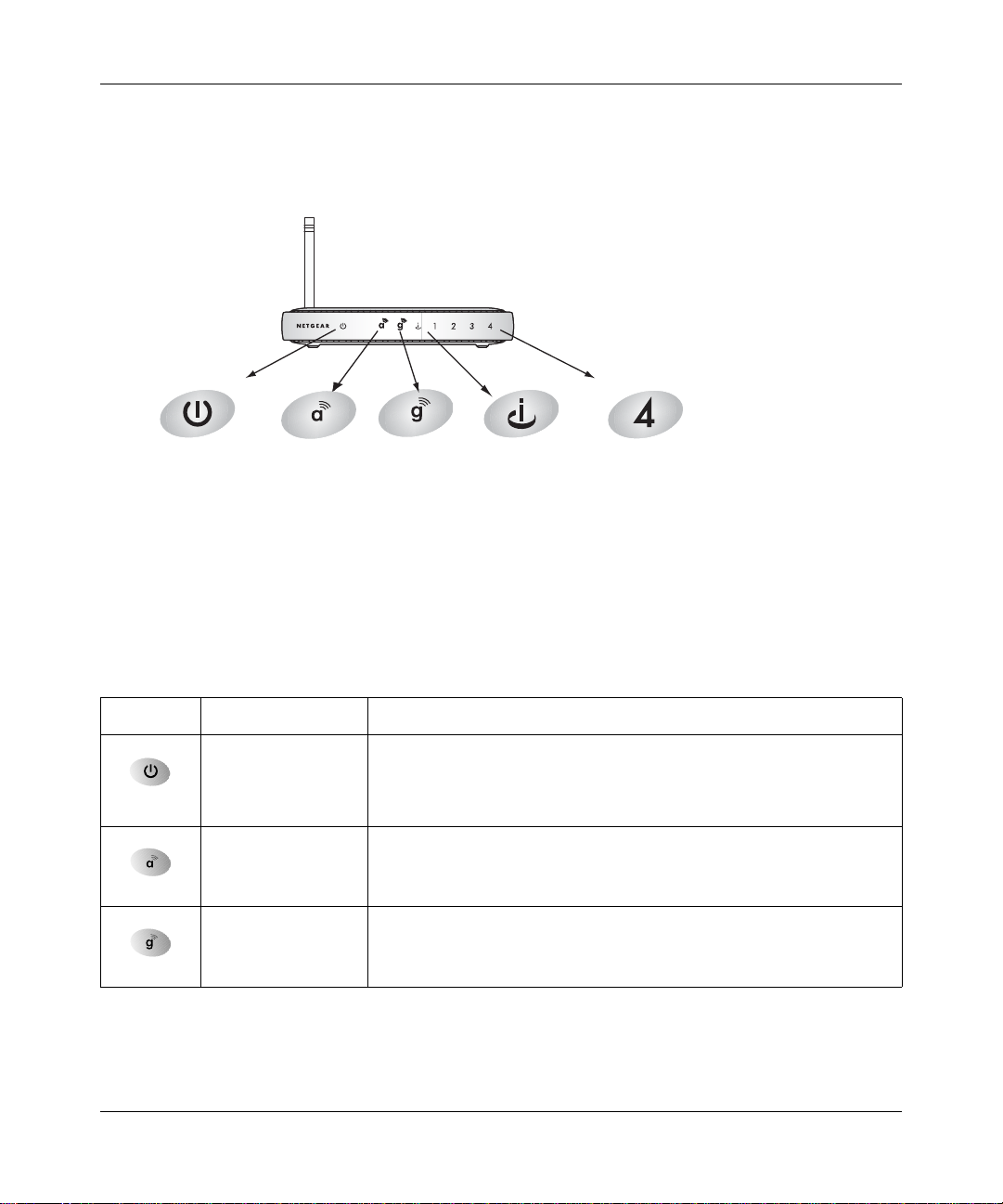
The Router’s Front Panel
The front panel of the WGU624 wireless router contains the status LEDs described below.
0OWER )NTERNET
7IRELESS
A
Figure 2-1: WGU624 Front Panel
7IRELESS
G
0ORT
,!.
0ORT
You can use some of the LEDs to verify connections. Viewed from left to right, the table below
describes the LEDs on the front panel of the router.
Table 2-1. LED Descriptions
Label Activity Description
On
Amber Blink
Off
Power
On The 802.11a wireless interface is enabled.
802.11a
On The 802.11g wireless interface is enabled.
802.11g
Power is supplied to the router.
Power is supplied to the router and it is performing its diagnostic test.
Power is not supplied to the router.
Introduction 2-7
M-10153-01
Page 22
Reference Manual for the Double 108 Mbps Wireless Firewall Router WGU624
Table 2-1. LED Descriptions
Internet
Local
On
Blink
On (Green)
Blink (Green)
On (Amber)
Blink (Amber)
Off
The Internet (WAN) port has detected a link with an attached device.
Data is being transmitted or received by the Internet port.
The Local (LAN) port has detected link with a 100 Mbps device.
Data is being transmitted or received at 100 Mbps.
The Local port has detected link with a 10 Mbps device.
Data is being transmitted or received at 10 Mbps.
No link is detected on this port.
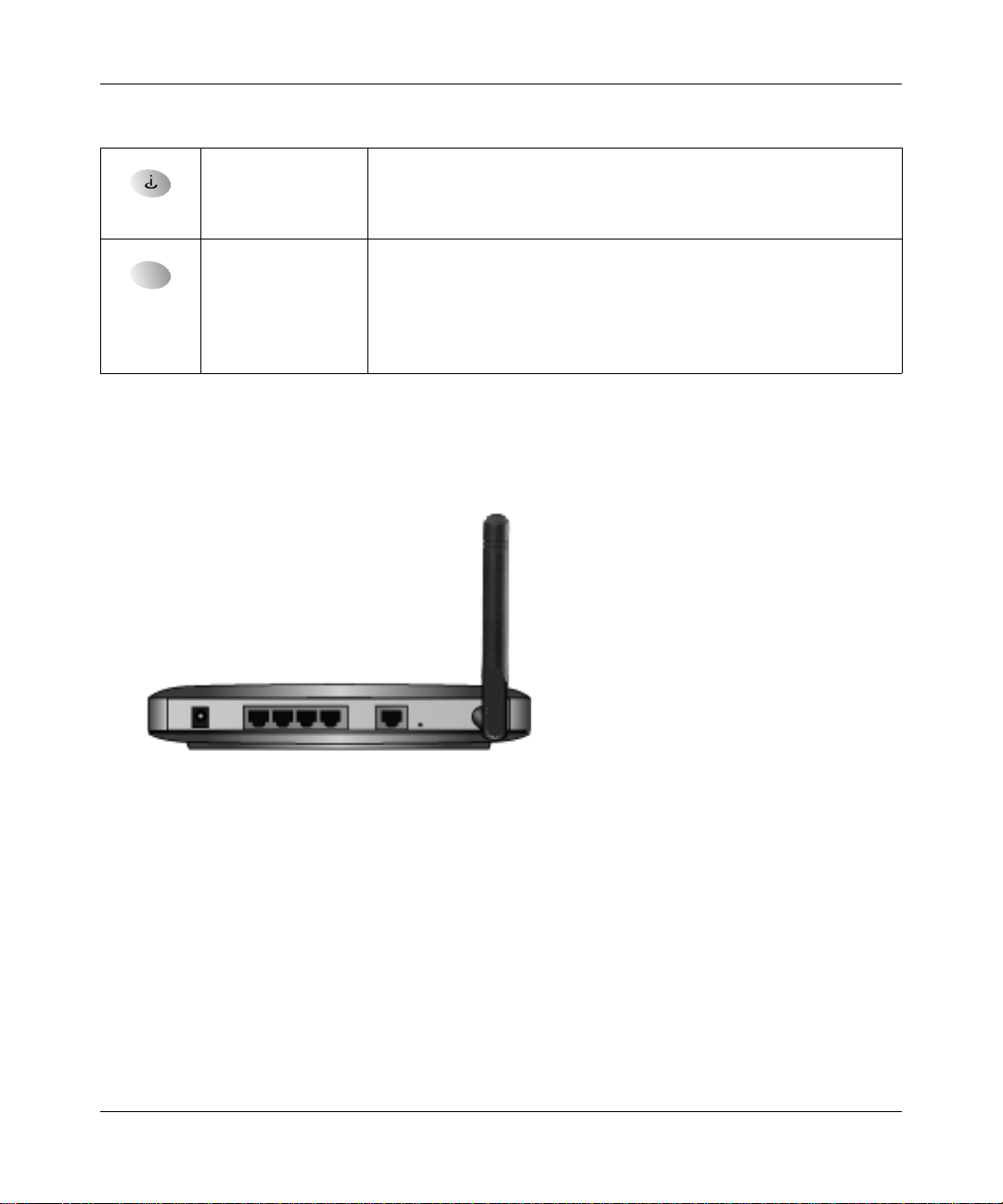
The Router’s Rear Panel
The rear panel of the WGU624 wireless router contains the port connections listed below.
Figure 1-2: WGU624 Rear Panel
Viewed from left to right, the rear panel contains the following features:
• AC power adapter outlet
• Four Local (LAN) 10/100 Mbps Ethernet ports, the fourth can be used with a DMZ server
• Internet (WAN) Ethernet port for connecting the router to a cable or DSL modem
• Factory Default Reset push button
• Wireless antenna
2-8 Introduction
M-10153-01
Page 23

Chapter 3
Connecting the Router to the Internet
This chapter describes how to set up the router on your local area network (LAN) and connect to
the Internet. You will find out how to configure your Double 108 Mbps Wireless Firewall Router
WGU624 for Internet access using the Setup Wizard, or how to manually configure your Internet
connection.
What You Will Need Before You Begin
You need to prepare these three things before you begin:
1. Have active Internet service such as that provided by an cable or DSL broadband account.
2. Locate the Internet Service Provider (ISP) configuration information for your DSL account.
3. Network capability to connect the router to a cable or DSL modem and a computer as
explained below.
Cabling and Computer Hardware Requirements
To use the WGU624 wireless router on your network, each computer must have an installed
Ethernet Network Interface Card (NIC) and an Ethernet cable. If the computer will connect to your
network at 100 Mbps, you must use a Category 5 (Cat 5) cable such as the one provided with your
router. The cab le or DSL broadband modem must provide a standard 10 Mbps (10BASE-T) or 100
Mbps (10BASE-Tx) Ethernet interface.
Computer Network Configuration Requirements
The WGU624 includes a built-in Web Configuration Manager. To access the configuration menus
on the WGU624, your must use a Java-enabled W e b browser program that supports HTTP uploads
such as Microsoft Internet Explorer or Netscape Navigator. Use Internet Explorer or Netscape
Navigator 4.0 or above.
For the initial setup of your router, you need to connect a computer to the router. This computer
has to be set to automatically get its TCP/IP configuration from the router via DHCP.
Connecting the Router to the Internet 3-1
M-10153-01
Page 24

Reference Manual for the Double 108 Mbps Wireless Firewall Router WGU624
Note: For help with DHCP configuration, please use the Windows TCP/IP Configuration
Tutorials on the Double 108 Mbps Wireless Router WGU624 Resource CD , or refer to
Appendix C, “Preparing Y our Network”.
Internet Configuration Requirements
Depending on how your ISP set up your Internet account, you will need one or more of these
configuration parameters to connect your router to the Internet:
• Host and Domain Names
• ISP Login Name and Password
• ISP Domain Name Server (DNS) Addresses
• Fixed IP Address which is also known as Static IP Address
Where Do I Get the Internet Configuration Parameters?
There are several ways you can gather the required Internet connection information.
• Your ISP provides all the information needed to connect to the Internet. If you cannot locate
this information, you can ask your ISP to provide it or you can try one of the options below.
• If you have a computer already connected using the active Internet access account, you can
gather the configuration information from that computer.
— For Windows 95/98/ME, open the Network control panel, select the TCP/IP entry for the
Ethernet adapter, and click Properties. Record all the settings for each tab page.
— For Windows 2000/XP, open the Local Area Network Connection, select the TCP/IP entry
for the Ethernet adapter, and click Properties. Record all the settings for each tab page.
— For Macintosh computers, open the TCP/IP or Network control panel. Record all the
settings for each section.
• You may also refer to the Double 108 Mbps Wireless Router WGU624 Resource CD for the
NETGEAR Router ISP Guide, which provides Internet connection information for many ISPs.
Once you locate your Internet configuration parameters, you may want to record them on the page
below.
3-2 Connecting the Router to the Internet
M-10153-01
Page 25

Reference Manual for the Double 108 Mbps Wireless Firewall Router WGU624
Record Your Internet Connection Information
Print this page. Fill in the configuration parameters from your Internet Service Provider (ISP).
ISP Login Name: The login name and password are case sensitive and must be entered exactly as
given by your ISP. Some ISPs use your full e-mail address as the login name. The Service Name is
not required by all ISPs. If you connect using a login name and password, then fill in the
following:
Login Name: ______________________________
Password: ____________________________
Service Name: _____________________________
Fixed or Static IP Address: If you have a static IP address, record the following information. For
example, 169.254.141.148 could be a valid IP address.
Fixed or Static Internet IP Address: ______
______ ______ ______
Gateway IP Address: ______ ______ ______ ______
Subnet Mask: ______ ______ ______ ______
ISP DNS Server Addresses: If you were given DNS server addresses, fill in the following:
Primary DNS Server IP Address: ______
______ ______ ______
Secondary DNS Server IP Address: ______ ______ ______ ______
Host and Domain Names: Some ISPs use a specific host or domain name like CCA7324-A or
home. If you haven’t been given host or domain names, you can use the following examples as a
guide:
• If your main e-mail account with your ISP is
Your ISP might call this your account, user, host, computer, or system name.
• If your ISP’s mail server is
mail.xxx.yyy.com, then use xxx.yyy.com as the domain name.
ISP Host Name: _________________________
For Wireless Access: For configuration of the wireless network, record the following:
Wireless Network Name (SSID): ___________ __ __ __ _
Encryption (circle one): WEP 64, or WEP 128
WEP passphrase or key: ____________________
aaa@yyy.com, then use aaa as your host name.
ISP Domain Name: _______________________
Connecting the Router to the Internet 3-3
M-10153-01
Page 26
Reference Manual for the Double 108 Mbps Wireless Firewall Router WGU624
Connecting the WGU624
This section provides instructions for connecting the Double 108 Mbps Wireless Firewall Router
WGU624. Also, the Double 108 Mbps Wireless Router WGU624 Resource CD included with
your router contains an animated Installation Assistant to help you through this procedure.
Connecting the Wireless Router
Follow the steps below to connect your router to your network. You can also refer to the Double
108 Mbps Wireless Router WGU624 Resource CD included with your router which contains an
animated Installation Assistant to help you through this procedure.
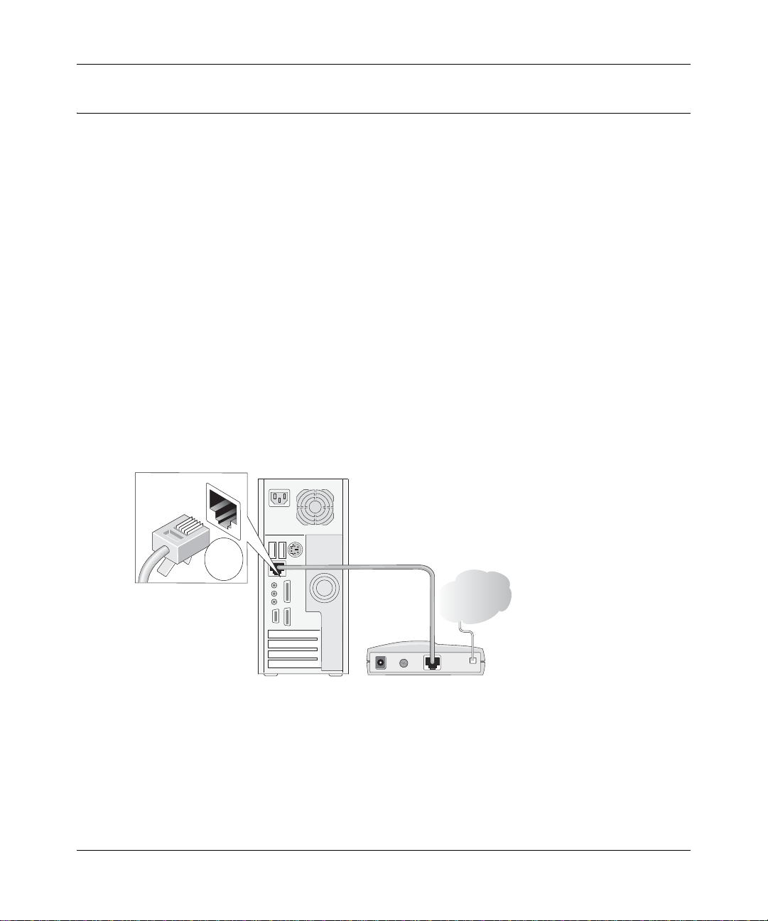
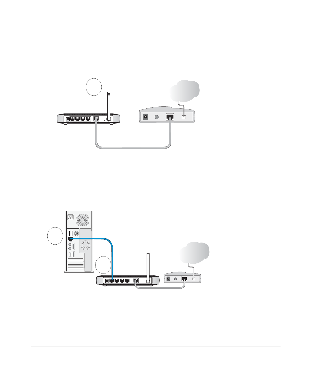
1. CONNECT THE WIRELESS ROUTER, THE COMPUTER, AND THE MODEM.
a. Turn off your computer and your cable or DSL modem.
b. Locate the Ethernet cable (Cable 1 in the diagram below) that connects your PC to the
modem.
c. Disconnect the cable at the computer end only, point A in the diagram.
A
&DEOH
,QWHUQHW
FRPSXWHU
Figure 3-1: Disconnect the Ethernet cable from the computer
d.
Look at the label on the bottom of the wireless router. Locate the Internet port. Securely
insert the Ethernet cable from your modem (Cable 1 in the diagram below) into the
Internet port of the wireless router as shown in point B in the diagram below.
3-4 Connecting the Router to the Internet
M-10153-01
PRGHP
Page 27
Reference Manual for the Double 108 Mbps Wireless Firewall Router WGU624
Note: Place the WGU624 wireless router in a location which conforms to the “Observing
Performance, Placement, and Range Guidelines” on page 4-1. The stand provided with the
WGU624 provides a convenient, space-saving way of installing the wireless router. Avoid
stacking it on other electronic equipment.
B
,QWHUQHW
SRUW
URXWHU
&DEOH
Figure 3-2: Connect the wireless router to the modem
e.
Securely insert the blue cable that came with your wireless router into a LAN port on the
router such as LAN port 4 (point C in the diagram), and the other end into the Ethernet
port of your computer (point D in the diagram).
D
%OXH1(7*($5
&DEOH
PRGHP
,QWHUQHW
,QWHUQHW
C
FRPSXWHU
Figure 3-3: Connect the computers on your network to the router
Your network cables are connected and you are ready to restart your network.
Connecting the Router to the Internet 3-5
URXWHU
/$13RUWV
PRGHP
M-10153-01
Page 28

Reference Manual for the Double 108 Mbps Wireless Firewall Router WGU624
RESTART YOUR NETWORK IN THE CORRECT SEQUENCE
2.
Warning: Failure to restart your network in the correct sequence could prevent you from
connecting to the Internet.
a. First, turn on the broadband modem and wait 2 minutes.
b. Now, plug in the power cord to the WGU624 and wait one minute.
c. Last, turn on your computer.
Note: For DSL customers, if software logs you in to the Internet do not run that software. You
may need to go to the Internet Explorer Tools Menu, Internet Options, Connections tab page where
you can select “Never dial a connection”.
d. Check the wireless router status lights to verify the following:
When you turn the router on, the power light goes on.
The Wireless a and g lights should be lit.
The router’s local LAN lights are lit for any computers that are connected to it.
The router’s Internet light is lit, indicating a link has been established to the cable
or DSL modem.
Note: For wireless placement and range guidelines, and wireless configuration
instructions, please see Chapter 4, “Wireless Configuration”.
3. O
PEN A BROWSER AND LOG IN TO THE WIRELESS ROUTER.
Note: To connect to the router, your computer needs to be configured to obtain an IP address
automatically via DHCP. If you need instructions on how to do this, please refer to
Appendix C, “Preparing Y our Network”.
a. Connect to the router by typing http://192.168.1.1 in the address field of Internet Explorer
or Netscape® Navigator.
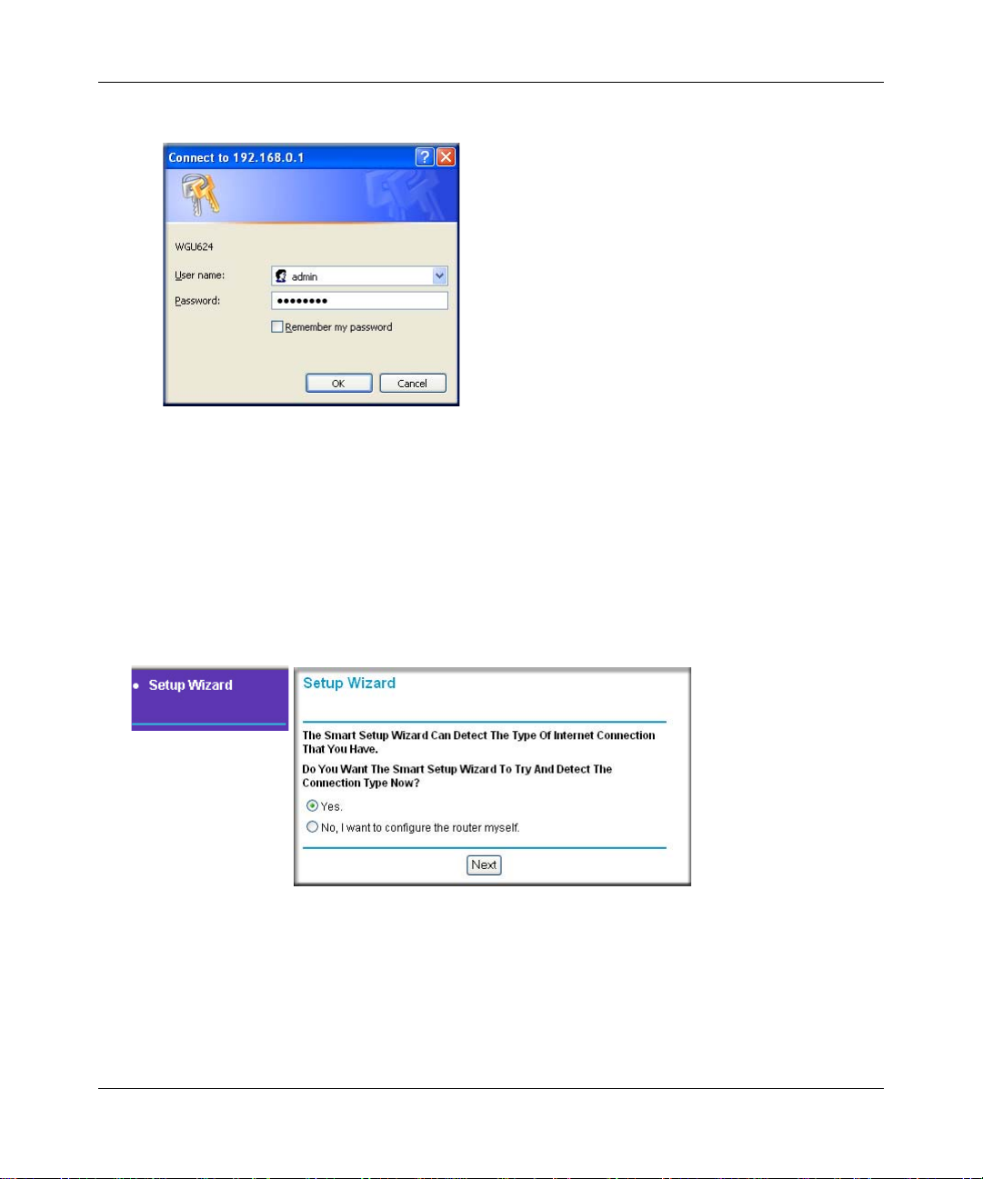
b. For security reasons, the router has its own user name and password. When prompted,
enter admin for the router user name and password for the router password, both in lower
case letters.
Note: The router user name and password are not the same as any user name or password
you may use to log in to your Internet connection.
3-6 Connecting the Router to the Internet
M-10153-01
Page 29
Reference Manual for the Double 108 Mbps Wireless Firewall Router WGU624
The login window is displayed below:
Figure 3-4: Login window
c.
Click OK.
Note: If you cannot connect to the wireless router, verify that your cables are connected
correctly, that the router is powered on. Verify that your computer is set to obtain the both IP
and DSN server addresses automatically, which is usually so. For help with this, see the
tutorials on the Resource CD.
4. C
ONNECT TO THE INTERNET
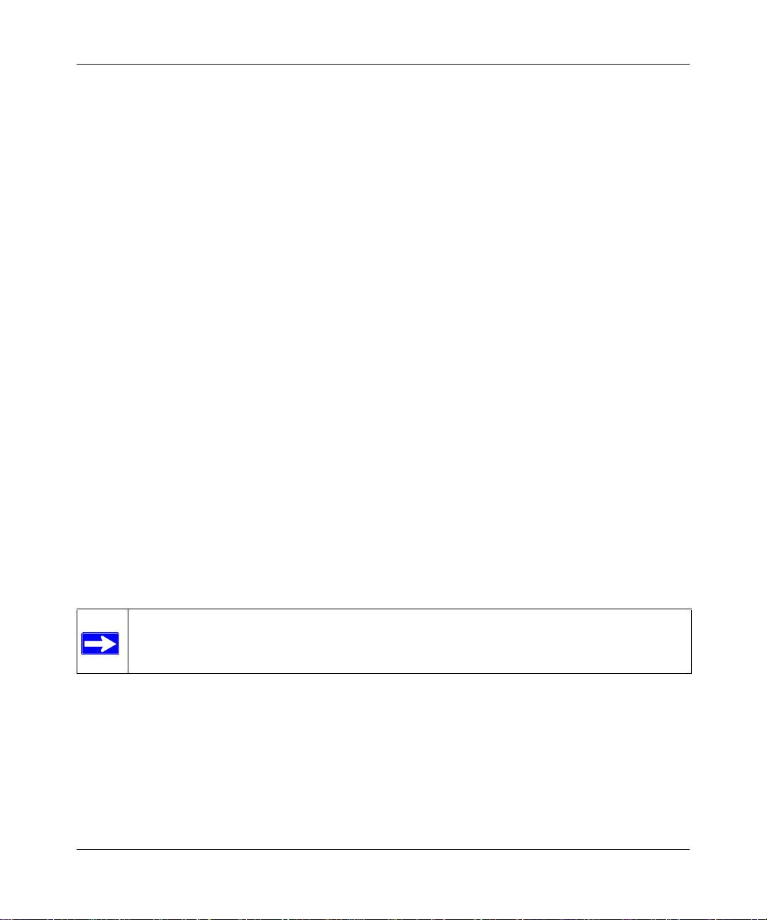
Figure 3-5: Setup Smart Wizard
a.
You are now connected to the router. If you do not see the menu above, click the Setup
Smart Wizard link on the upper left of the main menu.
Connecting the Router to the Internet 3-7
M-10153-01
Page 30
Reference Manual for the Double 108 Mbps Wireless Firewall Router WGU624
Click Next and follow the steps in the Setup Smart Wizard for inputting the configuration
b.
parameters from your ISP to connect to the Internet.
Note: If you choose not to use the Setup Smart Wizard, you can manually configure your
Internet connection settings by following the procedure “How to Manually Configure
Your Internet Connection” on page 3-9.
Unless your ISP automatically assigns your configuration automatically via DHCP, you
will need the configuration parameters from your ISP that you recorded in the form,
“Record Your Internet Connection Information” on page 3-3.
c. When the router successfully detects an active Internet service, the router’s Internet LED
goes on. The Setup Smart Wizard reports which connection type it discovered, and
displays the appropriate configuration menu. If the Setup Smart Wizard finds no
connection, you will be prompted to check the physical connection between your router
and the cable or DSL line.
d. The Setup Smart Wizard will report the type of connection it finds and prompts you for the
settings. The options are:
• Connections that require a login using protocols such as PPTP, Telstra Bigpond, or
PPPoE or Other broadband connections.
• Connections that use dynamic IP address assignment.
• Connections that use fixed IP address assignment.
e. When the router successfully detects an active Internet service, the router checks to see of
there is a new version of firmware available. If so, you will be prompted to upgrade your
firmware. Take advantage of this opportunity to assure that your wireless router is up to
date with the latest enhancements and features.
If you choose not to use the auto-update feature, you can check for new firmware by
following the procedure in “Upgrading the Router Software” on page 6-5.
Note: Be sure to check the NETGEAR Web site for documentation updates, which are
available at http://kbserver.netgear.com/products/WGU624.asp.
3-8 Connecting the Router to the Internet
M-10153-01
Page 31

Reference Manual for the Double 108 Mbps Wireless Firewall Router WGU624
How to Manually Configure Your Internet Connection
You can manually configure your router using the menu below, or you can allow the Setup W izard
to determine your configuration as described in the previous section.
ISP Does Not Require Login
ISP Does Require Login
Figure 3-6: Browser-based configuration Basic Settings menus
You can manually configure the router using the Basic Settings menu shown in Figure 3-6 using
these steps:
1. Click the Basic Settings link on the Setup menu.
Connecting the Router to the Internet 3-9
M-10153-01
Page 32

Reference Manual for the Double 108 Mbps Wireless Firewall Router WGU624
If your Internet connection does not require a login, click No at the top of the Basic Settings
2.
menu and fill in the settings according to the instructions below. If your Internet connection
does require a login, click Yes, and skip to step 3.
a. Enter your Account Name (may also be called Host Name) and Domain Name.
These parameters may be necessary to access your ISP’s services such as mail or news
servers.
b. Internet IP Address:
If your ISP has assigned you a permanent, fixed (static) IP address for your PC, select
“Use static IP address”. Enter the IP address that your ISP assigned. Also enter the IP
Subnet Mask and the Gateway IP address. The Gateway is the ISP’s router to which your
router will connect.
c. Domain Name Server (DNS) Address:
If you know that your ISP does not automatically transmit DNS addresses to the router
during login, select “Use these DNS servers” and enter the IP address of your ISP’s
Primary DNS Server. If a Secondary DNS Server address is available, enter it also.
Note: If you enter an address here, restart the computers on your network so that these
settings take effect.
d. Gateway’s MAC address:
This section determines the Ethernet MAC address that will be used by the router on the
Internet port. Some ISPs register the Ethernet MAC address of the network interface card
in your PC when your account is first opened. Then they only accept traffic from the MAC
address of that PC. This feature allows your router to masquerade as that PC by “cloning”
its MAC address.
To change the MAC address, select “Use this Computer’s MAC address.” The router will
capture and use the MAC address of the PC that you are now using. Y ou mu st be using the
one PC that is allowed by the ISP. Or, select “Use this MAC address” and enter it.
e. Click Apply to save your settings.
3. If your Internet connection does require a login, fill in the settings according to the instructions
below . Sel ect Yes if you normally must launch a login program such as Enternet or WinPOET
in order to access the Internet.
Note: After you finish setting up your router, you will no longer need to launch the ISP’s login
program on your PC in order to access the Internet. When you start an Internet application,
your router will automatically log you in.
3-10 Connecting the Router to the Internet
M-10153-01
Page 33

Reference Manual for the Double 108 Mbps Wireless Firewall Router WGU624
Select you Internet service provider from the drop-down list.
a.
Figure 3-7: Basic Settings ISP list
b.
The screen changes according to the ISP settings requirements of the ISP you select.
4. If your Internet connection does require a login, fill in the settings according to the instructions
below.
Note: After you finish setting up your router, you will no longer need to launch the ISP’s login
program on your computer in order to access the Internet. When you start an Internet
application, your router will automatically log you in.
a. Select your Internet service provider from the drop-dow n list. Your choices are:
• Other — if you have installed PPP software such as WinPoET (from Earthlink) or
Enternet (from Pacbell), then select Other. For more information, see “Manual PPPoE
Configuration” on page 3-11.
• PPTP — this protocol is used in Austria and other European countries. For more
information, see “Manual PPTP Configuration” on page 3-13.
• Telstra Bigpond — this protocol is used mainly in Australia. For more information,
see “Manual Telstra Bigpond Configuration” on page 3-15.
b. The screen changes according to the ISP settings requirements of the ISP you select.
c. Fill in the parameters for your Internet service provider.
d. Click Apply to save your settings. Click the Test button to verify you have Internet access.
Manual PPPoE Configuration
If your ISP uses PPPoE, select Other for the Internet Service Provider in the Basic Settings menu
to display the following menu:
Connecting the Router to the Internet 3-11
M-10153-01
Page 34

Reference Manual for the Double 108 Mbps Wireless Firewall Router WGU624
Figure 3-8: Other (PPPoE) menu
To configure your Internet service connection for Other (PPPoE), fill in the following fields:
• Enter the Login and Password as provided by your ISP. These fields are case sensitive.
• To change the login timeout, enter a new value in minutes. This determines how long the
router keeps the Internet connection active after there is no Internet activity from the LAN.
Entering a timeout value of zero means never log out.
• If you know that your ISP does not automatically transmit DNS addresses to the router during
login, select “Use these DNS servers” and enter the IP address of your ISP’s Primary DNS
Server. If a Secondary DNS Server address is available, enter it also.
Note: If you enter DNS addresses, restart your computers so that these settings take effect.
• Click Apply to save your settings.
• Click Test to verify that your Internet connection works. If the NETGEAR Web site does not
appear within one minute, refer to Chapter 8, “Troubleshooting”.
3-12 Connecting the Router to the Internet
M-10153-01
Page 35

Reference Manual for the Double 108 Mbps Wireless Firewall Router WGU624
Manual PPTP Configuration
If your ISP uses PPTP, select PPTP for the Internet Service Provider in the Basic Settings menu
and you will see the following menu:
Figure 3-9: PPTP menu
Connecting the Router to the Internet 3-13
M-10153-01
Page 36

Reference Manual for the Double 108 Mbps Wireless Firewall Router WGU624
To configure your Internet service connection for PPTP, fill in the following fields:
• Enter your Login and Password. These fields are case sensitive.
• To change the login timeout, enter a new value in minutes. This determines how long the
router keeps the Internet connection active after there is no Internet activity from the LAN.
Entering a timeout value of zero means never log out.
• Enter your IP address if your ISP provided a fixed IP address, such as 10.0.1.20. Otherwise,
leave the IP address set to 0.0.0.0 and you will be automatically assigned an IP address when
you connect.
• Enter a Server IP Address if your ISP provided one, such as 10.0.0.138. Otherwise, leave the
IP address set to 0.0.0.0 and the Server IP Address will be automatically supplied when you
connect.
• Normally the Connection ID/Name should be left blank. If your ISP provided one, then enter it
here.
• If you know that your ISP does not automatically transmit DNS addresses to the router during
login, select “Use these DNS servers” and enter the IP address of your ISP’s Primary DNS
Server. If a Secondary DNS Server address is available, enter it also.
Note: If you enter DNS addresses, restart your computers so that these settings take effect.
• The Router MAC Address section determines the Ethernet Mac address that will be used by
the router on the Internet port. Some ISPs will register the Ethernet MAC address of the
network interface card in your PC when your account is first opened. They will then only
accept traffic from the MAC address of that PC. This feature allows your router to masquerade
as that PC.
T o change the MAC address, select “Use this Computer’ s MAC address.” The router will then
capture and use the MAC address of the PC that you are now using. Y ou must be using the one
PC that is allowed by the ISP. Or, select “Use this MAC address” and enter it.
• Click Apply to save your settings.
• Click Test to test your Internet connection. If the NETGEAR Web site does not appear within
one minute, refer to Chapter 8, “Troubleshooting”.
3-14 Connecting the Router to the Internet
M-10153-01
Page 37

Reference Manual for the Double 108 Mbps Wireless Firewall Router WGU624
Manual Telstra Bigpond Configuration
If your ISP uses Telstra Bigpond, select Telstra Bigpond for the Internet Service Provider in the
Basic Settings menu and you will see the following menu:
Figure 3-10: Telstra Bigpond Cable menu
To configure your Internet service connection for Telstra Bigpond, fill in the following fields:
• Enter your Login, Password and Authentication Server. These fields are case sensitive.
• If you know that your ISP does not automatically transmit DNS addresses to the router during
login, select “Use these DNS servers” and enter the IP address of your ISP’s Primary DNS
Server. If a Secondary DNS Server address is available, enter it also.
Note: If you enter DNS addresses, restart your computers so that these settings take effect.
Connecting the Router to the Internet 3-15
M-10153-01
Page 38

Reference Manual for the Double 108 Mbps Wireless Firewall Router WGU624
• The Router Mac Address section determines the Ethernet MAC address that will be used by
the router on the Internet port. Some ISPs register the Ethernet MAC address of the network
interface card in your PC when your account is first opened. They will then only accept traffic
from the MAC address of that PC. This feature allows your router to masquerade as that PC.
T o change the MAC address, select “Use this Computer’ s MAC address.” The router will then
capture and use the MAC address of the PC that you are now using. Y ou must be using the one
PC that is allowed by the ISP. Or, select “Use this MAC address” and enter it.
• Click Apply to save your settings.
• Click Test to test your Internet connection. If the NETGEAR Web site does not appear within
one minute, refer to Chapter 8, “Troubleshooting”.
3-16 Connecting the Router to the Internet
M-10153-01
Page 39

Chapter 4
Wireless Configuration
This chapter describes how to configure the wireless features of your WGU624 wireless router. In
planning your wireless network, you should consider the level of security required. You should
also select the physical placement of your router in order to maximize the network speed. For
further information on wireless networking, refer to in Appendix D, “Wireless Networking
Basics”.
Observing Performance, Placement, and Range Guidelines
The operating distance or range of your wireless connection can vary significantly bas ed on the
physical placement of the wireless router. The latency, data throughput performance, and
notebook power consumption of wireless adapters also vary depending on your configuration
choices.
Note: Failure to follow these guidelines can result in significant performance
degradation or inability to wirelessly connect to the router. For complete range/
performance specifications, please see Appendix A, “Technical Specifications”.
For best results, place your router:
• Near the center of the area in which your PCs will operate.
• In an elevated location such as a high shelf where the wirelessly connected PCs have
line-of-sight access (even if through walls).
• Away from sources of interference, such as PCs, microwaves, and 2.4 GHz cordless phones.
• Away from large metal surfaces.
The time it takes to establish a wireless connection can vary depending on both your security
settings and placement. WEP connections can take slightly longer to establish. Also, WEP
encryption can consume more battery power on a notebook PC.
Wireless Configuration 4-1
M-10153-01
Page 40

Reference Manual for the Double 108 Mbps Wireless Firewall Router WGU624
Implementing Appropriate Wireless Security
Note: Indoors, computers can connect over 802.11b/g wireless networks at
ranges of up to 300 feet. Such distances can allow for others outside of your
immediate area to access your network.
Unlike wired network data, your wireless data transmissions can be received well beyond your
walls by anyone with a compatible adapter. For this reason, use the security features of your
wireless equipment. The WGU624 wireless router provides highly effective security features
which are covered in detail in this chapter. Deploy the security features appropriate to your needs.
:LUHOHVV'DWD
WGU624
5DQJHXSWRIRRWUDGLXV
2SHQV\VWHPHDV\EXWQRVHFXULW\
6HFXULW\2SWLRQV
0$&DFFHVVOLVWQRGDWDVHFXULW\
:(3VHFXULW\EXWVRPHSHUIRUPDQFHLPSDFW
:3$36.YHU\VWURQJVHFXULW\
Figure 4-1: WGU624 wireless data security options
There are several ways you can enhance the security of you wireless network.
• Restrict Access Based on MAC Address. You can restrict access to only trusted PCs so that
unknown PCs cannot wirelessly connect to the WGU624. MAC address filtering adds an
obstacle against unwanted access to your network, but the data broadcast over the wireless link
is fully exposed.
• Turn Off the Broadcast of the Wireless Network Name SSID. If you disable broadcast of
the SSID, only devices that have the correct SSID can connect. This nullifies the wireless
network “discovery” feature of some products such as Windows XP, but the data is still fully
exposed to a determined snoop using specialized test equipment like wireless sniffers.
4-2 Wireless Configuration
M-10153-01
Page 41

Reference Manual for the Double 108 Mbps Wireless Firewall Router WGU624
• WEP. Wired Equivalent Privacy (WEP) data encryption provides data security. WEP Shared
Key authentication and WEP data encryption will block all but the most determined
eavesdropper.
• WPA-PSK. Wi-Fi Protected Access (WPA) data encryption provides strong data security.
WPA-PSK will block eavesdropping. Because this is a new standard, wireless device driver
and software availability may be limited.
• Turn Off the Wireless LAN. If you disable the wireless LAN, wireless devices cannot
communicate with the router at all. You might choose to turn off the wireless the LAN when
you are away and the others in the household all use wired connections.
Wireless Mode Options
The following table shows the 802.11a and 802.11b/g settings for each Wireless Mode:
Table 4-1. Wireless Mode Options
Wireless Mode 11a Setting 11g Setting
802.11b/g modes:
b only
g+b
g only
Auto Super G 108 Mbps
Super G 108 Mbps only
802.11 a modes:
a only
Auto Super A 108 Mbps
Super A 108 Mbps only
any
run in 802.11b mode only
run in normal g+b mode
run in 802.11g mode only
run in Auto 108 Mbps
run in 108 Mbps only
any
run in normal a mode only
run in Auto 108 Mbps
run in 108 Mbps only
Wireless Configuration 4-3
M-10153-01
Page 42

Reference Manual for the Double 108 Mbps Wireless Firewall Router WGU624
Default Basic Wireless Settings
When you first receive your WGU624, the default factory settings in effect are shown in the table
below. You can restore these defaults with the factory default reset button on the rear panel.
Table 4-2. Default Wireless Settings
FEATURE DEFAULT SETTINGS
Wireless Access Point Enabled
Wireless Access List (MAC Filtering) All wireless stations allowed
SSID broadcast Enabled
SSID NETGEAR_11g for 802.11g
NETGEAR_11a for 802.11a
11b/g RF Channel 11
11 a RF Channel 36
Mode g and b for 802.11g
a only for 802.11a
Authentication Type WPA-PSK
WPA-PSK passphrase NETGEAR-ULTRA-G
After you install the WGU624 wireless router, use the procedures below to customize any of the
settings to better meet your networking needs.
Basic 802.11a Wireless Settings
To configure the 802.11a wireless settings of your router, click the Wireless a link in the main
menu of the browser interface. The Wireless 802.11a Settings menu appears, as shown in
“Wireless 802.11a Settings menu” on page 4-5.
4-4 Wireless Configuration
M-10153-01
Page 43

Reference Manual for the Double 108 Mbps Wireless Firewall Router WGU624
Figure 4-2: Wireless 802.11a Settings menu
The following options are available for the 802.11a configuration:
Name (SSID). The SSID is also known as the wireless network name. Enter a value of up to 32
alphanumeric characters. In a setting where there is more than one wireless network, different
wireless network names provide a means for separating the traffic. Any device you want to
participate in a particular wireless network must use this SSID for that network. The WGU624
default SSID is: NETGEAR_11a.
Region. This field identifies the region where the WGU624 can be used. It may not be legal to
operate the wireless features of the wireless router in a region other than one of those identified in
this field.
Channel. This field determines which operating frequency will be used. It should not be necessary
to change the wireless channel unless you notice interference problems with another nearby access
point. For more information on the wireless channel frequencies please refer to “Wireless
Channels” on page D-7.
Wireless Configuration 4-5
M-10153-01
Page 44

Reference Manual for the Double 108 Mbps Wireless Firewall Router WGU624
Wireless Mode. This field determines which data communications protocols will be used:
• a only — dedicates the WGU624 to communicating with 802.11a wireless devices
exclusively.
• 108 Mbps only — only compatible 802.11a wireless stations that support 108 Mbps can
connect.
• Auto 108 Mbps — all 802.11a and NETGEAR 108 Mbps wireless stations can be used.
Security Mode:
• Open System — allows any device to join the network, assuming that the device SSID
matches the router SSID. Alternatively, the device can use the “ANY” SSID option to
associate with any available router within range, regardless of its SSID.
• Shared Key — only those computers that possess the correct authentication key can join
the network.
• 802.1x — defines port-based, network access control used to provide authenticated
network access and automated data encryption key management. 802.1x uses a protocol
called EAP (Extensible Authentication Protocol).
• WPA-PSK — (Wi-Fi Protected Access Pre-Shared Key) — use WPA standard encryption
• WPA — (Wi-Fi Protected Access) — use WPA standard encryption
Cipher Type:
• Disable
• WEP (Wired Equivalent Privacy) — use WEP 64, 128 or 152 bit data encryption.
• AES — Advanced Encryption Standard, a symmetric 128-bit block data encryption
technique. It is an iterated block cipher with a variable block length and a variable key
length.
• TKIP — the Temporal Key Integrity Protocol mechanism shares a starting key between
devices. Each device then changes its encryption key for every packet.
Basic 802.11g Wireless Settings
To configure the 802.11 g wireless settings of your router, click the Wireless g link in the main
menu of the browser interface. The Wireless 802.11g Settings menu appears, as shown below.
4-6 Wireless Configuration
M-10153-01
Page 45

Reference Manual for the Double 108 Mbps Wireless Firewall Router WGU624
Figure 4-3: Wireless 802.11g Settings menu
The following options are available for the 802.11g configuration:
Name (SSID). The SSID is also known as the wireless network name. Enter a value of up to 32
alphanumeric characters. In a setting where there is more than one wireless network, different
wireless network names provide a means for separating the traffic. Any device you want to
participate in a particular wireless network must use this SSID for that network. The WGU624
default SSID is: NETGEAR_11g.
Region. This field identifies the region where the WGU624 can be used. It may not be legal to
operate the wireless features of the wireless router in a region other than one of those identified in
this field.
Channel. This field determines which operating frequency will be used. It should not be necessary
to change the wireless channel unless you notice interference problems with another nearby access
point. For more information on the wireless channel frequencies please refer to “Wireless
Channels” on page D-7.
Wireless Configuration 4-7
M-10153-01
Page 46

Reference Manual for the Double 108 Mbps Wireless Firewall Router WGU624
Wireless Mode. This field determines which data communications protocols will be used:
• g & b — both 802.11g and 802.11b wireless stations can be used.
• g only — only 802.11g wireless stations can be used.
• b only — all 802.11b wireless stations can be used. 802.11g wireless stations can still be
used if they can operate in 802.11b mode.
• 108 Mbps only — only compatible 802.11g wireless stations that support 108 Mbps can
connect.
• Auto 108 Mbps — all 802.11g, 802.11b and NETGEAR 108 Mbps wireless stations can
be used.
Note: If you select 108 Mbps mode, the router will only use channel 6.
The default is “g and b”, which allows both “g” and “b” wireless stations to access this device.
Security Mode:
• Open System — allows any device to join the network, assuming that the device SSID
matches the router SSID. Alternatively, the device can use the “ANY” SSID option to
associate with any available router within range, regardless of its SSID.
• Shared Key — only those computers that possess the correct authentication key can join
the network.
• 802.1x — defines port-based, network access control used to provide authenticated
network access and automated data encryption key management. 802.1x uses a protocol
called EAP (Extensible Authentication Protocol).
• WPA-PSK — (Wi-Fi Protected Access Pre-Shared Key) — use WPA standard encryption.
• WPA — (Wi-Fi Protected Access) — use WPA-PSK standard encryption.
Cipher Type:
• Disable — no data encryption
• WEP (Wired Equivalent Privacy) — use WEP 64, 128 or 152 bit data encryption.
• AES — Advanced Encryption Standard, a symmetric 128-bit block data encryption
technique. It is an iterated block cipher with a variable block length and a variable key
length.
• TKIP — the Temporal Key Integrity Protocol mechanism shares a starting key between
devices. Each device then changes its encryption key for every packet.
4-8 Wireless Configuration
M-10153-01
Page 47

Reference Manual for the Double 108 Mbps Wireless Firewall Router WGU624
Wireless Security Settings
The following table shows the 11a and 11g security mode and cipher type options:
Table 4-3. Wireless Security Settings
Security Mode Cipher Type
Open System WEP — 64, 128, or 152 bit encryption
Shared Key WEP — 64, 128, or 152 bit encryption
802.1x none
WPA-PSK AES or TKIP
WPA AES or TKIP
Instructions on how to configure the security settings are provided in the following sections.
WEP Authentication and Encryption
Restricting wireless access to your network prevents intruders from connecting to your network.
However, the wireless data transmissions are still vulnerable to snooping. Using the WEP data
encryption settings described below will prevent a determined intruder from eavesdropping on
your wireless data communications. Also, if you are using the Internet for such activities as
purchases or banking, those Internet sites use another level of highly secure encryption called SSL.
You can tell if a Web site is using SSL because the Web address begins with HTTPS rather than
HTTP.
Wireless Configuration 4-9
M-10153-01
Page 48

Reference Manual for the Double 108 Mbps Wireless Firewall Router WGU624
Security Mode Selection
Figure 4-4: Encryption Strength
The WGU624 lets you select the following wireless security modes with the WEP Cypher Type :
• Open System. With Open Network Authentication and 64-, 128-, or 152- bit WEP data
encryption, the WGU624 performs data encryption, but does not perform any authentication.
• Shared Key. Encrypts the SSID and data. Choose the Encryption Strength (64-, 128-, or
152-bit data encryption). Manually enter the key values or enter a word or group of printable
characters in the Passphrase box. Manually entered keys are case sensitive but Passphrase
characters are not case sensitive.
Note: Not all wireless adapter configuration utilities support Passphrase key generation.
Note: The security mode is separate from the data encryption cipher type. You
can choose the Shared Key security mode, but still leave the data transmissions
unencrypted. If you require strong security, use both the Shared Key and WEP
encryption settings.
Be sure to set your wireless adapter according to the authentication scheme you choose for the
WGU624 wireless router. Please refer to “Authentication and WEP” on page D-3 for a full
explanation of each of these options, as defined by the IEEE 802.11 wireless communication
standard.
Cipher Type Choices
Choose the encryption strength from the drop-down list. Please refer to “Overview of WEP
Parameters” on page D-5 for a full explanation of each of these options, as defined by the IEEE
802.11 wireless communication standard.
4-10 Wireless Configuration
M-10153-01
Page 49

Reference Manual for the Double 108 Mbps Wireless Firewall Router WGU624
• Disable. No encryption will be applied. This setting is useful for troubleshooting your wireless
connection, but leaves your wireless data fully exposed.
• 64-bit, 128-bit, or 152-bit WEP. When selected, WEP encryption will be applied. If
encryption strength is set to 128 bit or 152 bit, then only the selected WEP key box will
automatically be populated with key values.
If WEP is enabled, you can manually or automatically program the four data encryption keys.
These values must be identical on all PCs and access points in your network.
There are two methods for creating WEP encryption keys:
• Passphrase. Enter a word or group of printable characters in the Passphrase box and click the
Generate button. These characters are case sensitive.
• Manual. For 64-bit WEP, enter 10 hexadecimal digits (any combination of 0-9, a-f, or A-F).
For 128-bit WEP, enter 26 hexadecimal digits (any combination of 0-9, a-f, or A-F). For
152-bit WEP, enter 32 hexadecimal digits (any combination of 0-9, a-f, or A-F). These values
are not case sensitive.
WPA Encryption
You can select WPA-PSK or WPA for the Security Mode. The default is WPA-PSK.
WPA-Pre-shared Key performs authentication, uses 128-bit data encryption and dynamically
changes the encryption keys, making it nearly impossible to circumvent.
You must use the same wireless security settings on the client adapters to properly implement
WPA security.
Figure 4-5: Security Modes
Wireless Configuration 4-11
M-10153-01
Page 50

Reference Manual for the Double 108 Mbps Wireless Firewall Router WGU624
Cipher Type Choices
• AES. Advanced Encryption Stan dard, a symmetric 128-bit block data encryption technique. It
is an iterated block cipher with a variable block length and a variable key length. The block
length and the key length can be independently specified to 128, 192 or 256 bits.The U.S
government adopted the algorithm as its encryption technique in October 2000, replacing the
DES encryption it used. AES works at multiple network layers simultaneously.
• TKIP. The Temporal Key Integrity Protocol mechanism shares a starting key between devices.
Each device then changes their encryption key for every packet. It is extremely difficult for
hackers to read messages — even if they have intercepted the data.
Passphrase
The Passphrase must be identical on all PCs and access points in your network. Enter a word or
group of printable characters in the Passphrase box. These characters are case sensitive.
Key Update
The default Key Update is 0 for unlimited updates. You can change this to a value between 15 and
1800.
Radius Server Settings
• Enter the Radius Server IP address.
• The Radius Port number is 1812 by default.
• Enter a Radius Secret, which can be up to 32 alphanumeric characters
Note: Not all wireless adapter configuration utilities support WPA. Furthermore, client software is
required on the client. Windows XP and Windows 2000 with Service Pack 3 do include the client
software that supports WPA. Neverthele ss, the wireless adapter hardware and driver must also
support WPA.
4-12 Wireless Configuration
M-10153-01
Page 51

Reference Manual for the Double 108 Mbps Wireless Firewall Router WGU624
Recording Your SSID and Security Settings
Before customizing your wireless settings, print this form and record the following information.
802.11a Wireless Network Name (SSID): ______________________________
802.11g Wireless Network Name (SSID): ______________________________
The Service Set Identification (SSID), called the wireless network name in Windows XP,
identifies the wireless network. You may use up to 32 alphanumeric characters. The SSID in the
wireless router is the SSID you configure in the wireless adapter card. For the access point and
wireless nodes to communicate with each other, all must be configured with the same SSID.
If WEP Authentication is Used. Circle one: Open System, Shared Key, or Auto.
Note: If you select Shared Key, the other devices in the network will not connect unless they are
set to Shared Key as well.
— WEP Encryption Strength. Choose the key size. Circle one: 64, 128, or 152 bit.
— Data Encryption (WEP) Keys. The WGU624 provides two methods for creating WEP
encryption keys:
• Passphrase. ___________________________ ___
characters. These characters are case sensitive. When you enter the Passphrase and
click the Generate button on the WGU624, the keys will be gene rated.
• Manual. For 64-bit WEP, enter 10 hexadecimal digits (any combination of 0-9 or a-f).
These values are not case sensitive. For 128-bit WEP, enter 26 hex digits. For 152-bit
WEP, enter 32 hex digits. Record the key values in the spaces below.
Key 1: ________________________________
Key 2: ________________________________ Key 4:_________________________________
If WPA-PSK Authentication is Used. Enter a word or group of printable characters. These
characters are case sensitive. When you use WPA-PSK, the other devices in the network will not
connect unless they are set to WPA-PSK and are configured with the correct Passphrase.
— Passphrase. ___________________________ __ _
Store this information in a safe place. Use the procedures described in the following sections to
configure the WGU624.
Wireless Configuration 4-13
Key 3:_________________________________
M-10153-01
Enter a word or group of printable
Page 52

Reference Manual for the Double 108 Mbps Wireless Firewall Router WGU624
Setting Up and Testing Basic Wireless Connectivity
Follow the instructions below to set up and test basic wireless connectivity. Once you have
established basic wireless connectivity , you can enable security settings appropriate to your needs.
1. Log in to the WGU624 wireless router at its default LAN address of http://192.168.1.1 with its
default user name of admin and default password of password, or using whatever LAN
address and password you have set up.
2. Click the Wireless a or g Settings link in the main menu of the WGU624.
Figure 4-6: Wireless Settings menu
3.
Choose a suitable descriptive name for the wireless network name (SSID). In the SSID box,
enter a value of up to 32 alphanumeric characters. The default SSID is NETGEAR_11a for
802.11a and NETGEAR_11g for 802.11g.
Note: The SSID of any wireless access adapters must match the SSID you configure in the
Double 108 Mbps Wireless Firewall Router WGU624. If they do not match, you will not get a
wireless connection to the WGU624.
4. Set the Region. Select the region in which the wireless interface will operate.
5. Set the Channel.
This field determines which operating frequency will be used. It should not be necessary to
change the wireless channel unless you notice interference problems with another nearby
wireless router or access point. Select a channel that is not being used by any other wireless
networks within several hundred feet of your router. For more information on the wireless
channel frequencies please refer to “Wireless Channels” on page D-7.
6. For initial configuration and test, leave the Cipher Type set to “Disabled”.
7. Click Apply to save your changes.
4-14 Wireless Configuration
M-10153-01
Page 53

Reference Manual for the Double 108 Mbps Wireless Firewall Router WGU624
Note: If you are configuring the router from a wireless PC and you change the router’s
SSID, channel, or security settings, you will lose your wireless connection when you
click Apply. You must then change the wireless settings of your PC to match the
router’s new settings.
8.
Configure and test your PCs for wireless connectivity.
Program the wireless adapter of your PCs to have the same SSID and channel that you
configured in the router. Check that they have a wireless link and are able to obtain an IP
address by DHCP from the router.
Once your PCs have basic wireless connectivity to the router, then you can configure the advanced
wireless security functions of the router.
Restricting Wireless Access by MAC Address
To restrict access based on MAC addresses, follow these steps:
1. Log in to the WGU624 wireless router at its default LAN address of http://192.168.1.1 with its
default user name of admin and default password of password, or using whatever LAN
address and password you have set up.
A
Note: When configuring the router from a wireless PC whose MAC address is not in the
Trusted PC list, if you select Turn Ac cess Control On, you will lose your wireless
connection when you click on Apply. You must then access the wireless router from a
wired PC or from a wireless PC which is on the access control list to make any further
changes.
2. Click the Advanced Wireless a or Advanced Wireless g Settings link in the main menu of the
WGU624 wireless router.
Wireless Configuration 4-15
M-10153-01
Page 54

Reference Manual for the Double 108 Mbps Wireless Firewall Router WGU624
Click the Setup Access List button to display the Wireless Card Access menu shown below.
3.
Figure 4-7: Wireless Card Access List Setup
4.
Click Add to add a wireless device to the wireless access control list. The Available Wireless
Cards list displays.
5. Click the Turn Access Control On check box.
6. Then, either select from the list of available wireless cards the WGU624 has found in your
area, or enter the MAC address and device name for a device you plan to use. You can usually
find the MAC address printed on the wireless adapter.
Note: You can copy and paste the MAC addresses from the router’s Attached Devices menu
into the MAC Address box of this menu. To do this, configure each wireless PC to obtain a
wireless link to the router. The PC should then appear in the Attached Devices menu.
7. Click Add to add this wireless device to the Wireless Card Access List. The screen changes
back to the list screen. Repeat these steps for each additional device you wish to add to the list.
8. Be sure to click Apply to save your wireless access control list settings.
Now, only devices on this list will be allowed to wirelessly connect to the WGU624.
4-16 Wireless Configuration
M-10153-01
Page 55

Reference Manual for the Double 108 Mbps Wireless Firewall Router WGU624
Configuring WEP
To configure WEP data encryption, follow these steps:
Note: If you use a wireless PC to configure the WEP settings, you will be disconnected
when you click Apply. You must then either configure your wireless adapter to match
the wireless router WEP settings or access the wireless router from a wired PC to make
any further changes.
1. Log in to the WGU624 at its default LAN address of http://192.168.1.1 with its default user
name of admin and default password of password, or using whatever LAN address and
password you have set up.
2. Click the Wireless Settings a or g link in the main menu of the WGU624.
3. From the Security Encryption menu drop-down list, select the WEP encryption strength you
will use.
Figure 4-8. Wireless Security Encryption menu
You can manually or automatically program the four data encryption keys. These values must
4.
be identical on all PCs and Access Points in your network.
• Automatic — enter a word or group of printable characters in the Passphrase box and click
the Generate button. The four key boxes will be automatically populated with key values.
• Manual — enter 10 hexadecimal digits (any combination of 0-9, a-f, or A-F)
Select which of the four keys will be active.
Please refer to “Overview of WEP Parameters” on page D-5 for a full explanation of each of
these options, as defined by the IEEE 802.11 wireless communication standard.
5. Click Apply to save your settings.
Wireless Configuration 4-17
M-10153-01
Page 56

Reference Manual for the Double 108 Mbps Wireless Firewall Router WGU624
Configuring WPA-PSK Encryption Security
Wi-Fi Protected Access (WPA) is wireless security with far greater protection than WEP.
WPS-PSK (pre-shared key) uses encryption of a shared key as the starting point. WPA has a
significant advantages over WEP — an encryption key differing in every packet. It is extremely
difficult for hackers to read messages even if they have intercepted the data.
To enable WPA-PSK Encryption Security:
1. Click the Wireless Settings a or g link in the main menu of the WGU624 wireless router.
2. Select WPA-PSK.
Figure 4-9: WPA-PSK Security Configuration
3.
For the Cipher Type, select AES or TKIP.
4. Enter a Passphrase. The Passphrase can be between 8 and 63 characters. The default
Passphrase is NETGEAR-ULTRA-G.
5. The default for the Key Update time is 0, which is unlimited. If you want to limit the key
Update period, select a value between 15 and 1800 seconds.
6. Click Apply.
For more information on WPA security, see “WPA Wireless Security” on page D-8.
4-18 Wireless Configuration
M-10153-01
Page 57

Reference Manual for the Double 108 Mbps Wireless Firewall Router WGU624
Configuring Advanced Wireless Settings
The advanced wireless settings are configured separately for the 802.11a and 802.11g protocols.
Default Advanced Wireless Settings
The default advanced wireless settings are shown in the table below.
Note: These settings should work for most networks and should not be changed unless you have a
specific reason to do so.
Table 4-4. Default Advanced Wireless Settings
FEATURE 802.11a 802.11g
SSID Broadcast Enabled Enabled
Super A / Super G mode Enabled Enabled
eXtended Range Enabled Enabled
Adaptive Radio not applicab le Disabled
Transmit Power Max Max
Fragmentation Threshold 2346 2346
CRS/RTS Threshold 2346 2346
Preamble Mode Automatic Automatic
DTIM 1 1
Wireless Configuration 4-19
M-10153-01
Page 58
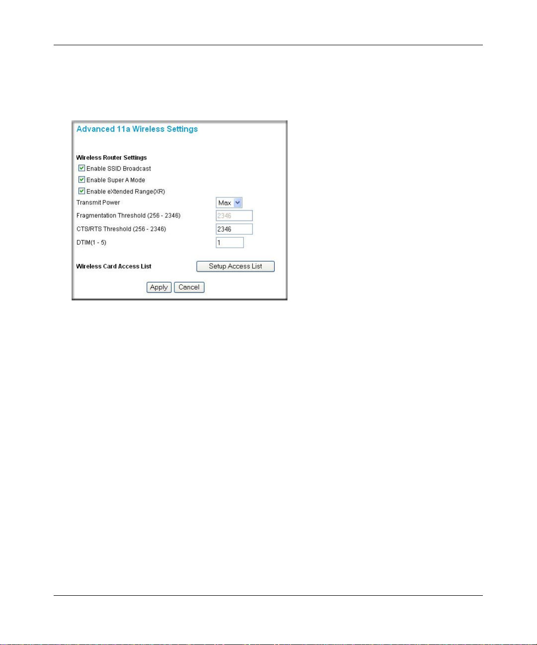
Reference Manual for the Double 108 Mbps Wireless Firewall Router WGU624
Configuring Advanced 802.11a Wireless Settings
From the main menu, click Advanced a Wireless Settings to view the configuration menu shown
below.
Figure 4-10: Advanced 802.11a Wireless Settings
• Enable SSID Broadcast — allow Broadcast of Network Name (SSID). If you disable
broadcast of the SSID, only devices that have the correct SSID can connect. Disabling SSID
broadcast nullifies the wireless network ‘discovery’ feature of some products such as
Windows XP.
• Enable Super A Mode — if enabled, the Wireless Router will enable data compression, packet
bursting and large frame support.
• Enable eXtended Range — eXtended Range (XR) technology provides significantly longer
range than basic 802.11 by maintaining connectivity when signals are made fainter when
passing through dense walls, floors, or other barriers. XR products require no additional
configuration and are fully interoperable with standard 802.11 technologies.
Note: The XR feature is NOT available when the wireless mode is “108Mbps only”.
• Transmit Power — Max, 75%, 50%, 25%, or Min. The default is Max.
• Fragmentation Threshold — value can be from 256 to 2346. The default is 2346.
• CRS/RTS Threshold — value can be from 256 to 2346. The default is 2346.
4-20 Wireless Configuration
M-10153-01
Page 59
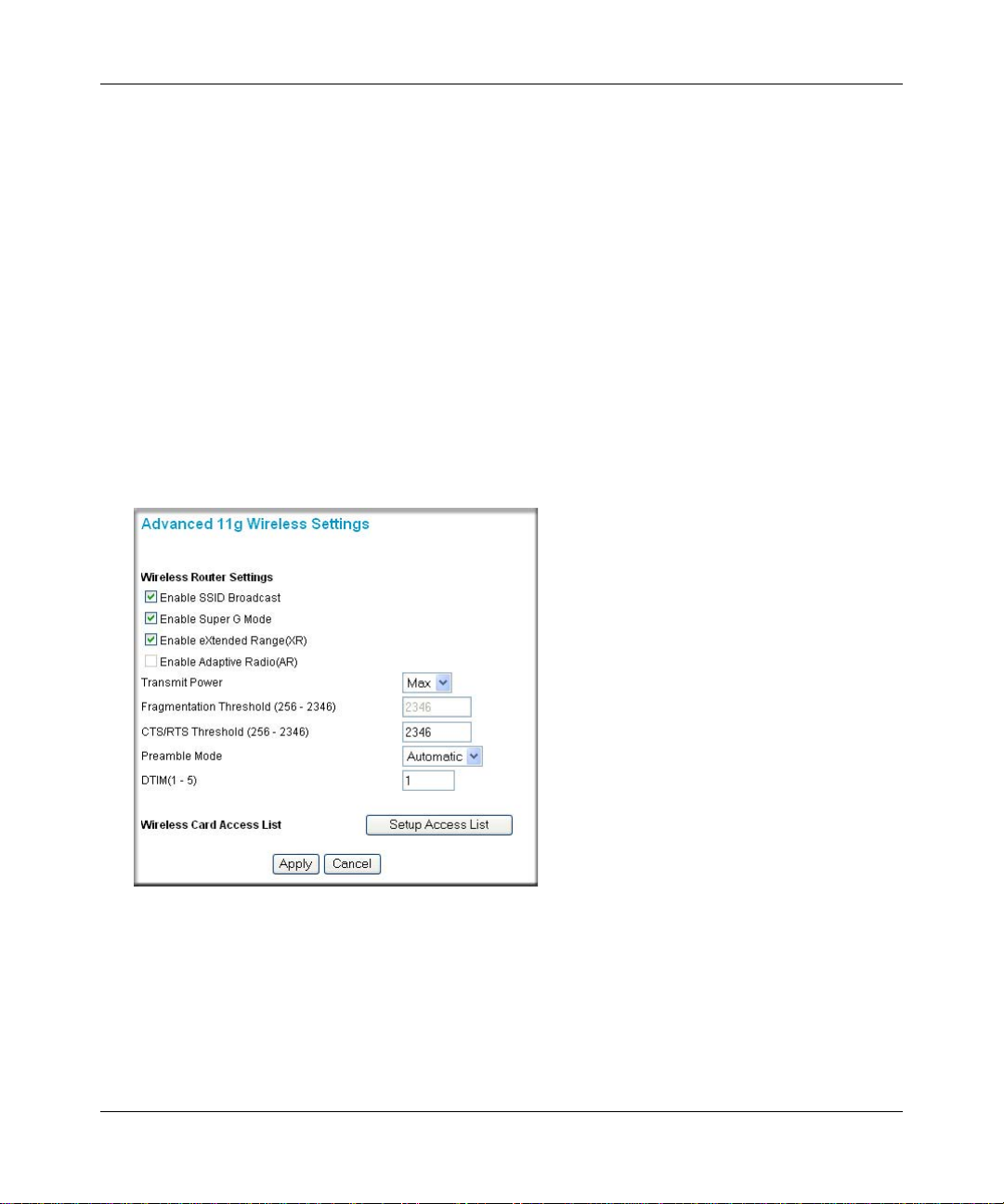
Reference Manual for the Double 108 Mbps Wireless Firewall Router WGU624
• DTIM — from 1 to 5. The default is 1. DTIM stands for Delivery Traffic Indication Message.
This setting determines how often the Access Point's Beacon (Traffic Indication Message)
contains a DTIM. The DTIM tells client devices in power-save mode that a packet is waiting
for them. The default setting causes client devices using power-save mode to wake up. To
conserve battery power in client devices using power-save mode, increase the Data Beacon
Rate (DTIM) setting. However, setting the DTIM too high may cause a wireless client to lose
its network connection.
• Wireless Card Access List — when the Trusted PCs Only radio button is selected, the
WGU624 checks the MAC address of the wireless station and only allows connections to PCs
identified on the trusted PCs list.
Configuring Advanced 802.11b/g Wireless Settings
From the main menu, click Advanced g Wireless Settings to view the configuration menu shown
below.
Figure 4-11: Advanced 802.11g Wireless Settings
• Enable SSID Broadcast — allow broadcast of the Network Name (SSID). If you disable
broadcast of the SSID, only devices that have the correct SSID can connect. Disabling SSID
broadcast nullifies the wireless network ‘discovery’ feature of some products such as
Windows XP.
Wireless Configuration 4-21
M-10153-01
Page 60

Reference Manual for the Double 108 Mbps Wireless Firewall Router WGU624
• Enable Super G Mode — if enabled, the wireless router will enable data compression, packet
bursting and large frame support.
• Enable eXtended Range — eXtended Range (XR) technology provides significantly longer
range than basic 802.11 by maintaining connectivity when signals are made fainter when
passing through dense walls, floors, or other barriers. XR products require no additional
configuration and are fully interoperable with standard 802.11 technologies.
Note: The XR feature is NOT available when the wireless mode is “108Mbps only” and “b only”.
• Enable Adaptive Radio — the Adaptive Radio (AR) feature is an option that is available when
the wireless settings are switched to the Auto 108 mode. When enabled, the Auto 108 mode
slows the data rate down automatically to the standard 802.11g (11g or 11b) mode and operate
at 54 Mbps or below when it senses any other neighboring wireless networks that are using
adjacent wireless channels. It steps up to a maximum data rate of 108 Mbps when it senses that
no other neighboring wireless networks are using adjacent channels. NETGEAR 108 Mbps
Wireless Products provide minimum interference to neighboring networks, so the default
setting for the Adaptive Radio feature is set to “Disable”.
• Transmit Power —Max, 75%, 50%, 25%, or Min. The default is Max.
• Fragmentation Threshold — value can be from 256 to 2346. The default is 2346.
• CRS/RTS Threshold — value can be from 256 to 2346. The default is 2346.
• Preamble Mode — Automatic or Long. The default is Automatic. Most access points and
client adapters have a setting called Preamble T ype — Short or Long. The default “Automatic”
will automatically pick Short or Long preamble type depending on the client capability.
• DTIM — from 1 to 5. The default is 1. DTIM stands for Delivery Traffic Indication Message.
This setting determines how often the Access Point's Beacon (Traffic Indication Message)
contains a DTIM. The DTIM tells client devices in power-save mode that a packet is waiting
for them. The default setting causes client devices using power-save mode to wake up. To
conserve battery power in client devices using power-save mode, increase the Data Beacon
Rate (DTIM) setting. However, setting the DTIM too high may cause a wireless client to lose
its network connection.
• Wireless Card Access List — when the Trusted PCs Only radio button is selected, the
WGU624 checks the MAC address of the wireless station and only allows connections to PCs
identified on the trusted PCs list.
4-22 Wireless Configuration
M-10153-01
Page 61

Chapter 5
Content Filtering
This chapter describes how to use the content filtering features of the Double 108 Mbps Wireless
Firewall Router WGU624 to protect your network. These features can be found by under the
Content Filtering heading in the main menu of the browser interface.
The Double 108 Mbps Wireless Firewall Router WGU624 provides you with Web content
filtering options, plus browsing activity reporting and instant alerts via e-mail. Parents and
network administrators can establish restricted access policies based on time-of-day, Web
addresses and Web address keywords. You can also block Internet access by applications and
services, such as chat or games.
Blocking Access to Internet Sites
The WGU624 wireless router allows you to restrict access based on Web addresses and Web
address keywords. Up to 255 entries are supported in the Keyword list.
To block access to Internet Sites, select Block Sites under the Content Filtering heading in the
main menu of the Web browser interface.
Keyword application examples:
• If the keyword "XXX" is specified, the URL <http://www.badstuff.com/xxx.html> is blocked.
• If the keyword “.com” is specified, only Web sites with other domain suffixes (such as .edu or
.gov) can be viewed.
• If you want to block all Internet browsing access during a scheduled period, enter the keyword
“.” and set the schedule in the Schedule menu.
Content Filtering 5-1
M-10153-01
Page 62

Reference Manual for the Double 108 Mbps Wireless Firewall Router WGU624
The Block Sites menu is shown below:
Figure 5-1: Block Sites menu
To enable keyword blocking, select either “Per Schedule” or “Always”, then click Apply. If you
want to block by schedule, be sure that a time period is specified in the Schedule menu.
To add a keyword or domain, type it in the Keyword box, click Add Keyword, then click Apply.
To delete a keyword or domain, select it from the list, click Delete Keyword, then click Apply.
T o specify a Trusted User, enter that PC’s IP address in the Trusted User box and click Apply. You
may specify one Trusted User , which is a PC that will be exempt from blocking and logging. Since
the Trusted User will be identified by an IP address, you should configure that PC with a fixed IP
address.
5-2 Content Filtering
M-10153-01
Page 63

Reference Manual for the Double 108 Mbps Wireless Firewall Router WGU624
Blocking Access to Internet Services
The WGU624 wireless router allows you to block the use of certain Internet services by PCs on
your network. This is called services blocking or port filtering. The Block Services menu is shown
below:
Figure 5-2: Block Services menu
Services are functions performed by server computers at the request of client computers. For
example, Web servers serve Web pages, time servers serve time and date information, and game
hosts serve data about other players’ moves. When a computer on your network sends a request for
service to a server computer on the Internet, the requested service is identified by a service or port
number. This number appears as the destination port number in the transmitted IP packets. For
example, a packet that is sent with destination port number 80 is an HTTP (Web server) request.
To enable service blocking, select either Per Schedule or Always, then click Apply. If you want to
block by schedule, be sure that a time period is specified in the Schedule menu.
To spec ify a service for blocking, click Add.
Content Filtering 5-3
M-10153-01
Page 64

Reference Manual for the Double 108 Mbps Wireless Firewall Router WGU624
The Block Services Setup menu is shown below:
Figure 5-3: Block Services Setup menu
From the Service Type list, select the application or service to be allowed or blocked. The list
already displays several common services, but you are not limited to these choices. To add any
additional services or applications that do not already appear, select User Defined.
Configuring a User Defined Service
To define a service, first you must determine which port number or range of numbers is used by
the application. The service numbers for many common protocols are defined by the Internet
Engineering Task Force (IETF) and published in RFC1700, “Assigned Numbers.” Service
numbers for other applications are typically chosen from the range 1024 to 65535 by the authors of
the application. This information can usually be determined by contacting the publisher of the
application or from user groups of newsgroups.
Enter the Starting Port and Ending Port numbers. If the applicatio n uses a single port number , enter
that number in both boxes.
If you know that the application uses either TCP or UDP , select the appropriate protocol. If you are
not sure, select Both.
5-4 Content Filtering
M-10153-01
Page 65

Reference Manual for the Double 108 Mbps Wireless Firewall Router WGU624
Configuring Service Blocking by IP Address Range
Under “Filter Services For”, you can block the specified service for a single PC, a range of PCs
(having consecutive IP addresses), or all PCs on your network.
Scheduling When Blocking Will Be Enforced
The WGU624 wireless router allows you to specify when blocking will be enforced. The Schedul e
menu is shown below:
Figure 5-4: Schedule menu
Use the check boxes on this menu to create a schedule for blocking content. Then click Apply.
Time Zone. Select your local time zone. This setting will be used for the blocking schedule and
for time-stamping log entries.
Content Filtering 5-5
M-10153-01
Page 66

Reference Manual for the Double 108 Mbps Wireless Firewall Router WGU624
Adjust for Daylight Savings Time. If your region uses Daylight Savings Time, you must
manually select Adjust for Daylight Savings Time on the first day of Daylight Savings Time, and
clear this check box at the end. Enabling Daylight Savings Time will cause one hour to be added to
the standard time.
Enable System Clock. Uses the system clock in the router.
Synchronize Time. Syncs up the router time with a NETGEAR time server, so that the Logs,
e-mail timestamps and other information will have the current time.
Days to Block. Select days to block by checking the appropriate boxes. Select Everyday to check
the boxes for all days. Click Apply.
Time of Day to Block. Select a start and end time in 23:59 format. Select All day for 24 hour
blocking. Click Apply.
Viewing Logs of Web Access or Attempted Web Access
The log is a detailed record of which Web sites you have accessed or attempted to access. Up to
128 entries are stored in the log. Log entries only appear when keyword blocking is enabled, and
no log entries are made for the Trusted User. An example is shown below:
Figure 5-5: Logs menu
5-6 Content Filtering
M-10153-01
Page 67

Reference Manual for the Double 108 Mbps Wireless Firewall Router WGU624
Log entries are described in Table 5-1
Table 5-1. Log entry descriptions
Field Description
Number The index number of the content filter log entries. Up to 128 entries are
available numbered from 0 to 127. The log keeps a record of the latest
128 entries.
Action This field displays whether the access was blocked or allowed.
Web site The name or IP address of the Web site or newsgroup visited or
attempted to access.
Source IP The IP address of the initiating device for this log entry.
Date and Time The date and time the log entry was recorded.
Log action buttons are described in Table 5-2
Table 5-2. Log action buttons
Button Description
Refresh Refresh the log screen.
Clear Log Clear the log entries.
Send Log E-mail the log immediately.
Content Filtering 5-7
M-10153-01
Page 68

Reference Manual for the Double 108 Mbps Wireless Firewall Router WGU624
Configuring E-Mail Alert and Web Access Log Notifications
In order to receive logs and alerts by e-mail, you must provide your e-mail information in the
E-mail menu, shown below:
Figure 5-6: E-mail menu
Turn E-mail notification on: Select this check box if you wish to receive e-mail logs and alerts
from the router.
Outgoing mail server: Enter the name of your ISP’s outgoing (SMTP) mail server (such as
mail.myISP.com). You may be able to find this information in the configuration menu of your
e-mail program. If you leave this box blank, log and alert messages will not be sent via e-mail.
E-mail address: Enter the e-mail address to which logs and alerts are sent. This e-mail address
will also be used as the From address. If you leave this box blank, log and alert messages will not
be sent via e-mail.
Sending Alerts and Logs
You can specify that logs are automatically sent to the specified e-mail address with these options:
5-8 Content Filtering
M-10153-01
Page 69

Reference Manual for the Double 108 Mbps Wireless Firewall Router WGU624
• Send alert immediately
Select this check box if you would like immediate notification of attempted access to a
blocked site.
• Send logs according to this schedule
Specifies how often to send the logs: None, Hourly, Daily, Weekly, or When Full.
– Day for sending log. Specifies which day of the week to send the log. Relevant when the
log is sent weekly or daily.
– Time for sending log. Specifies the time of day to send the log. Relevant when the log is
sent daily or weekly.
If the Weekly, Daily or Hourly option is selected and the log fills up before the specified
period, the log is automatically e-mailed to the specified e-mail address. After the log is sent, it
is cleared from the router’s memory. If the router cannot e-mail the log file, the log buffer may
fill up. In this case, the router overwrites the log and discards its contents. If you do not want
logs sent, select None. When you turn on e-mail notification and choose None in the Send
Logs According to This Schedule list, the alert is sent but not the log.
Content Filtering 5-9
M-10153-01
Page 70

Reference Manual for the Double 108 Mbps Wireless Firewall Router WGU624
5-10 Content Filtering
M-10153-01
Page 71

Chapter 6
Maintenance
This chapter describes how to use the maintenance features of your Double 108 Mbps Wireless
Firewall Router WGU624. These features can be found by clicking on the Maintenance heading in
the main menu of the browser interface.
Viewing Wireless Router Status Information
The Router Status menu provides a limited amount of status and usage information. From the main
menu of the browser interface, click Router Status to view the status screen, shown below.
Figure 6-1: Router Status screen
Maintenance 6-1
M-10153-01
Page 72

Reference Manual for the Double 108 Mbps Wireless Firewall Router WGU624
The Router Status screen displays the following parameters:
Table 6-1. Menu 3.2 - Wireless Router Status Fields
Field Description
Account Name The Host Name assigned to the router.
Firmware Version The router firmware version.
Internet Port These parameters apply to the Internet (WAN) port of the router.
MAC Address The Media Access Control address being used by the In ternet (WAN) port of the
router.
IP Address The IP address used by the Internet (WAN) port of the router. If no address is
shown, the router cannot connect to the Internet.
IP Subnet Mask The IP Subnet Mask used by the Internet (WAN) port of the router.
DHCP If set to None, the router is configured to use a fixed IP address on the WAN.
If set to Client, the router is configured to obtain an IP address dynamically from the
ISP.
LAN Port These parameters apply to the Local (L AN) port of the router.
MAC Address The Media Access Control address used by the LAN port of the router.
IP Address The IP address used by the Local (LAN) port of the router. The default is
192.168.1.1.
DHCP Identifies if the router’s built-in DHCP server is active for the LAN attached devices.
IP Subnet Mask The IP Subnet Mask used by the Local (LAN) port of the router. The default is
255.255.255.0
Wireless Port A These parameters apply to the Wireless a port of the router.
Name (SSID) The wireless network name (SSID) being used by the wireless port of the router.
The default is NETGEAR_11a.
Channel Identifies if the channel the wireless port is using. See “Wireless Channels” on
page D-7 for the frequencies used on each channel.
Wireless Mode 802.11a, 108 Mbps, or Auto
Wireless Port G These parameters apply to the Wireless g port of the router.
Name (SSID) The wireless network name (SSID) used by the wireless port of the router. The
default is NETGEAR_11g.
Channel Identifies if the channel the wireless port is using. See “Wireless Channels” on
page D-7 for the frequencies used on each channel.
Wireless Mode 802.11b+g, b only, g only, 108 Mbps, or Auto
6-2 Maintenance
M-10153-01
Page 73
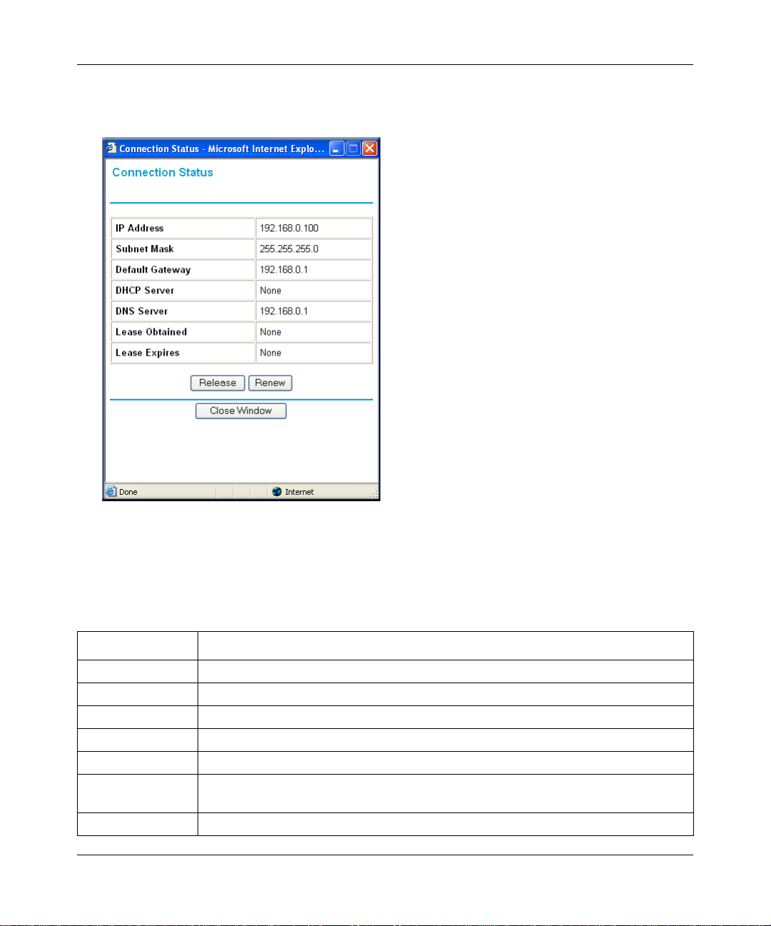
Reference Manual for the Double 108 Mbps Wireless Firewall Router WGU624
From the Router Status screen, click the “Connection Status” button to display the connection
status, as shown below.
Figure 6-2: Connection Status screen
This screen shows the following statistics:.
Table 6-1. Connection Status Fields
Field Description
IP Address The WAN (Internet) IP Address assigned to the router.
Subnet Mask The WAN (Internet) Subnet Mask assigned to the router.
Default Gateway The WAN (Internet) default gateway the router communicates with.
DHCP Server The DHCP server on the network.
DNS Server The DNS server on the network.
Lease Obtained The length of time the router has been connected to your Internet service provider’s
network.
Lease Expires The time the lease expires.
Maintenance 6-3
M-10153-01
Page 74

Reference Manual for the Double 108 Mbps Wireless Firewall Router WGU624
Click the Renew button to renew the DHCP lease.
From the Router Status screen, click the “Show Statistics” button to display router usage statistics,
as shown below.
Figure 6-3: Router Statistics screen
This screen shows the following statistics:
Table 6-1. Router Statistics Fields
Field Description
Port The statistics for the WAN (Internet) and LAN (local) ports. For each port, the screen
displays:
Status The link status of the port.
TxPkts The number of packets transmitted on this port since reset or manual clear.
RxPkts The number of packets received on this port since reset or manual clear.
Collisions The number of collisions on this port since reset or manual clear.
Tx B/s The current transmission (outbound) bandwidth used on the WAN and LAN ports.
Rx B/s The current reception (inbound) bandwidth used on the WAN and LAN ports.
Up Time The time elapsed since this port acquired the link.
Poll Interval Specifies the intervals at which the statistics are updated in this window. Click Stop to
freeze the display.
6-4 Maintenance
M-10153-01
Page 75

Reference Manual for the Double 108 Mbps Wireless Firewall Router WGU624
Show Statistics action buttons are described in Table 6-2.
Table 6-2. Show Statistics action buttons
Field Description
Set Interval Enter a time and click the button to set the polling frequency.
Stop Click the Stop button to freeze the polling information.
Viewing a List of Attached Devices
The Attached Devices menu contains a table of all IP devices that the router has discovered on the
local network. From the main menu of the browser interface, under the Maintenance heading,
select Attached Devices to view the table, shown below.
Figure 6-4: Attached Devices menu
For each device, the table shows the IP address, NetBIOS Host Name (if available), and Ethernet
MAC address. Note that if the router is rebooted, the table data is lost until the router rediscovers
the devices. To force the router to look for attached devices, click the Refresh button.
Upgrading the Router Software
The routing software of the WGU624 wireless router is stored in FLASH memory, and can be
upgraded as new software is released by NETGEAR.
Note: The Web browser used to upload new firmware into the WGU624 wireless router must
support HTTP uploads. Use Microsoft Internet Explorer or Netscape Navigator 4.0 or above. Do
not interrupt the upgrade process once it has started.
Maintenance 6-5
M-10153-01
Page 76

Reference Manual for the Double 108 Mbps Wireless Firewall Router WGU624
Note: Be sure to check the NETGEAR Web site for documentation updates, which are
available at http://kbserver.netgear.com/products/WGU624.asp.
From the main menu of the browser interface, under the Maintenance heading, select the Router
Upgrade heading to display the menu shown below.
Figure 6-5: Router Upgrade menu
Note: When uploading software to the WGU624 wireless router, it is important not to interrupt the
Web browser b y clo sing the window, clicking a link, or loading a new page. If the browser is
interrupted, it may corrupt the software. When the upload is complete, your router will
automatically restart. The upgrade process will typically take about one minute.
To check for new firmware:
1. Click Check. If the WGU624 finds new firmware is available, follow the on-screen prompts to
download in install the new firmware.
To upload firmware from your hard drive:
1. In the Router Upgrade menu, click the Browse button and browse to the location of the
upgrade file.
2. Click Upload.
In some cases, you may need to reconfigure the router after upgrading.
6-6 Maintenance
M-10153-01
Page 77

Reference Manual for the Double 108 Mbps Wireless Firewall Router WGU624
Configuration File Management
The configuration settings of the WGU624 wireless router are stored within the router in a
configuration file. This file can be saved (backed up) to a user’s PC, retrieved (restored) from the
user’s PC, or cleared to factory default settings.
From the main menu of the browser interface, under the Maintenance heading, select the Backup
Settings heading to bring up the menu shown below.
Figure 6-6: Backup Settings menu
Three options are available, and are described in the following sections.
Restoring and Backing Up the Configuration
The Restore and Backup options in the Settings Backup menu allow you to save and retrieve a file
containing your router’s configuration settings.
To save your settings, select the Backup tab. Click the Backup button. Your browser extracts the
configuration file from the router and prompts you for a location on your PC to store the file. You
can give the file a meaningful name at this time, such as pacbell.cfg.
T o restore your settings from a saved configuration file, enter the full path to the fil e on your PC or
click the Browse button to browse to the file. When you have located it, click the Restore button to
send the file to the router. The router then reboots automatically.
Maintenance 6-7
M-10153-01
Page 78

Reference Manual for the Double 108 Mbps Wireless Firewall Router WGU624
Erasing the Configuration
It is sometimes desirable to restore the router to the factory default settings. This can be done by
using the Erase function, which will restore all factory settings. After an erase, the router's
password will be password, the LAN IP address will be 192.168.1.1, and the router's DHCP client
will be enabled.
To era se the configuration, click the Erase button.
To restore the factory default configuration settings without knowing the login password or IP
address, you must use the default reset button on the rear panel of the router. See “Restoring the
Default Configuration and Password” on page 8-7.
Changing the Administrator Password
The default password for the router’s Web Configuration Manager is password. NETGEAR
recommends that you change this password to a more secure password.
From the main menu of the browser interface, under the Maintenance heading, select Set Password
to bring up the menu shown below.
Figure 6-7: Set Password menu
To change the password, first enter the old password, and then enter the new password twice.
Click Apply.
6-8 Maintenance
M-10153-01
Page 79

Chapter 7
Advanced Configuration
This chapter describes how to configure the advanced features of your Double 108 Mbps W ireless
Firewall Router WGU624. These features can be found under the Advanced heading in the main
menu of the browser interface.
Comparison of Port Triggering and Port Forwarding
Port Triggering is an advanced feature that can be used for gaming and other Internet applications.
Port Forwarding can typically be used to enable similar functionality, but it is static and has some
limitations.
Using the Port Forwarding / Port Triggering page, you can make local computers or servers
available to the Internet for different services (for example, FTP or HTTP), to play Internet games
(like Quake III), or to use Internet applications (like CUseeMe).
• Port Forwarding is designed for FTP, Web Server or other server based services. Once port
forwarding is set up, requests from the Internet are forwarded to the proper server.
• Port triggering only allows requests from the Internet after a designated port is 'triggered'. Port
triggering applies to chat and Internet games.
– Port Triggering opens an incoming port temporarily and does not require the server on the
Internet to track your IP address if it is changed by DHCP, for example.
– Port Triggering monitors o utbound traffic. When the router detects traffic on the specified
outbound port, it remembers the IP address of the computer that sent the data and
“triggers” the incoming port. Incoming traffic on the triggered port is then forwarded to
the triggering computer .
Advanced Configuration 7-1
M-10153-01
Page 80

Reference Manual for the Double 108 Mbps Wireless Firewall Router WGU624
Configuring Port Forwarding
For the services, applications, or games, that already exist in the pull-down list, you only need to
specify the computer's IP address. Otherwise, the port number and computer's IP address for each
service, game or application should be specified by clicking the Add Custom Service button.
Port Assignment
You can make up to 20 different port assignments for Internet services, applications or games. In
the Service Name lists, you can select either a service, application or game. If you do not see an
item that you want to use in any of the lists, check with the software or game developer for the
correct port numbers to use.
For Internet Services
Before starting, you need to determine which type of services you will provide and the IP address
of the computer that will provide those services. The most common services you would provide
are a Web (HTTP) server or FTP server.
To se t up a computer or server to be accessible to the Internet for an Internet service:
1. From the main menu, under the Advanced heading, select Port Forwarding/Port Triggering.
2. Select Port Forwarding to display the menu shown below:
Figure 7-1: Port Forwarding Menu
7-2 Advanced Configuration
M-10153-01
Page 81
Reference Manual for the Double 108 Mbps Wireless Firewall Router WGU624
Select the Internet service you want to use from the Service Name list. If the service does not
3.
appear in the list, refer to the section “Adding a Port Forwarding Custom Service” on
page 7-3.
4. Type the IP address of the computer in the Server IP Address box.
5. Click the Add button.
Note: You may have a single computer or server available for more than one type of service. To
do that, select another service, and type the same IP address for that computer or server.
For Internet Games or Applications
Although the router causes your entire local network to appear as a single machine to the Internet,
you can make a local server (for example, a Web server or game server) visible and available to
the Internet.
.
Note: If you are unfamiliar with networking and routing, refer to Appendix B,
“Network, Routing, Firewall, and Basics”, to become more familiar with the terms and
procedures used in this manual.
Use the Port Forwarding menu to configure the router to forward incoming protocols to computers
on your local network. In addition to servers for specific applications, you can also specify a
default DMZ server to which all other incoming protocols are forwarded. The DMZ server must be
connected to LAN port 4 on the WGU624. The DMZ port feature can be enabled in the WAN
Setup menu. See “Configuring WAN Setup Options” on page 7-6 for more information.
Before starting, you need to determine which type of service, application or game you will provide
and the IP address of the computer that will provide each service. Be sure the computer’s IP
address never changes. To configure port forwarding to a local server:
1. From the Service Name box, select the service or game that you will host on your network.
2. Enter the IP address of the local server in the corresponding Server IP Address box.
3. Click the Add button.
Adding a Port Forwarding Custom Service
To define a service, game or application that does not appear in the Service Name list, you must
determine which port numbers are used by the service. For this information, you may need to
contact the manufacturer of the program that you want to use. When you have the port number
information, follow these steps:
Advanced Configuration 7-3
M-10153-01
Page 82

Reference Manual for the Double 108 Mbps Wireless Firewall Router WGU624
Click the Add Custom Service button.
1.
2. Enter the first port number in an unused Starting Port box.
3. To forward only one port, enter it again in the Ending Port box. To specify a range of ports,
enter the last port to be forwarded in the End Port box.
4. Enter the IP address of the local server in the corresponding Server IP Address box.
5. Type a name for the service.
6. Click Apply at the bottom of the menu.
Adding Additional Computers
To set up an additional computer to play, for example Hexen II or KALI:
1. Click the Add Custom Service button.
2. Type the service name in the Service Name box.
3. Type the beginning port number in the Starting Port box.
For these games, use the supplied number in the default listing and add +1 for each additional
computer. For example, if you have already configured one computer to play Hexen II using
port 26900, the second computer's port number would be 26901, the third computer's port
number would be 26902.
4. Type the same port number in the Ending Port box.
5. Type the IP address of the computer in the Server IP Address box.
6. Click the Add button.
Local Web and FTP Server Example
If a local PC with a private IP address of 192.168.1.33 acts as a Web and FTP server, configure the
Port Forwarding menu to forward HTTP (port 80) and FTP (port 21) to local address 192.168.1.33.
In order for a remote user to access this server from the Internet, the remote user must know the IP
address that has been assigned by your ISP. If this address is 172.16.1.23, for example, an Internet
user can access your Web server by directing the browser to http://172.16.1.23. The assigned IP
address can be found in the Maintenance Status Menu, where it is shown as the WAN IP Address.
Some considerations for this application are:
• If your account’s IP address is assigned dynamically by your ISP, the IP address may change
periodically as the DHCP lease expires.
7-4 Advanced Configuration
M-10153-01
Page 83

Reference Manual for the Double 108 Mbps Wireless Firewall Router WGU624
• If the IP address of the local PC is assigned by DHCP, it may change when the PC is rebooted.
To avoid this, you can manually configure the PC to use a fixed address.
• Local PCs must access the local server using the PCs’ local LAN address (192.168.1.33 in this
example). Attempts by local PCs to access the server using the external IP address
(172.16.1.23 in this example) will fail.
Some online games and videoconferencing applications are incompatible with NAT. The
WGU624 wireless router is programmed to recognize some of these applications and to work
properly with them, but there are other applications that may not function well. In some cases, one
local PC can run the application properly if that PC’s IP address is entered as the default in the Port
Forwarding Menu. If one local PC acts as a game or videoconferencing host, enter its IP address as
the default.
Configuring Port Triggering
To define a game or application for Port Triggering, you must determine what port numbers are
used by the service. For this information, you may need to contact the manufacturer of the program
that you wish to use. When you have the port number information, follow these steps:
1. From the main menu of the browser interface, under the Advanced section, select Port
Forwarding/Port Triggering.
2. Select Port Triggering to display the Port Triggering screen, as shown below.
Figure 7-2: Port Triggering menu
Advanced Configuration 7-5
M-10153-01
Page 84

Reference Manual for the Double 108 Mbps Wireless Firewall Router WGU624
Click the Add button.
3.
4. Type a name for the service.
5. Enter unused port numbers for the Outgoing Start Port an d E nd Port. To trigger only one port,
enter it again in the Outgoing End Port box. To specify a range of ports, enter the last port to
be triggered in the End Port box.
6. Enter unused port numbers for the Incoming Start Port and End Port. T o trigger only on e port,
enter it again in the Incoming End Port box. To specify a range of ports, enter the last port to
be forwarded in the End Port box.
7. Enter the IP address of the local server or computer in the corresponding Server IP Address
box.
8. Click Add.
9. Select the Turn on Port Triggering check box.
10. Specify the Port Triggering Timeout value.
11. Click Apply at the bottom of the menu to save your new configuration.
Configuring WAN Setup Options
The WAN Setup options let you enable the DMZ port, change the MTU size and enable the
wireless router to respond to a Ping on the WAN port. These options are discussed below.
Figure 7-3: WAN Setup menu.
7-6 Advanced Configuration
M-10153-01
Page 85

Reference Manual for the Double 108 Mbps Wireless Firewall Router WGU624
Enable DMZ Port: LAN port 4 on the WGU624 is reserved to be used as the DMZ port. You can
also use this port as a regular LAN port when this feature is not enabled. The DMZ port feature is
helpful when using some online games and videoconferencing applications that are incompatible
with NAT. The router is programmed to recognize some of these applications and to work
properly with them, but there are other applications that may not function well. In some cases, one
local PC can run the application properly if that PC is connected directly to LAN port 4 as the
default DMZ server.
Note: DMZ servers pose a security risk. A computer designated as the default DMZ
server loses much of the protection of the firewall, and is exposed to exploits from the
Internet. However, the WGU624 provides a hardware DMZ port, which is much more
secure than a software solution. When enabled, the DMZ port is in a separate LAN sector
from the other LAN ports, including the Wireless LAN.
Incoming traffic from the Internet is normally discarded by the router unless the traffic is a
response to one of your local computers or a service that you have configured in the Ports menu.
Instead of discarding this traffic, you can have it forwarded to one computer on your network. This
computer is called the default DMZ server.
To forward traffic to the DMZ server:
1. From the Main Menu of the browser interface, under Advanced, click Port Forwarding/Port
Triggering.
2. Select Port Forwarding to display the Port Forwarding menu.
3. Select the Internet service you want to forward from the Service Name list. If the service does
not appear in the list, refer to the section “Adding a Port Forwarding Custom Service” on
page 7-3.
4. Enter the IP address of the DMZ server in the corresponding Server IP Address box.
5. Click Apply at the bottom of the menu.
Respond to Ping on Internet Port: If you want the router to respond to a 'ping' from the Internet,
select the Respond to Ping on Internet Port check box. This should only be used as a diagnostic
tool, since it allows your router to be discovered. Don't check this box unless you have a specific
reason to do so.
Disable SPI: Normally , this option should be Enabled, so that your local network will be protected
by the Stateful Packet Inspection (SPI) firewall included in the WGU624. However, certain
communications functions like VPN may require turning off the SPI feature.
Advanced Configuration 7-7
M-10153-01
Page 86

Reference Manual for the Double 108 Mbps Wireless Firewall Router WGU624
MTU Size: The default MTU size is usually fine. The normal MTU (Maximum Transmit Unit)
value for most Ethernet networks is 1500 Bytes. For some ISPs, particularly some using PPPoE,
you may need to reduce the MTU. This should not be done unless you are sure it is necessary for
your ISP.
Any packets sent through the router that are larger than the configured MTU size will be
repackaged into smaller packets to meet the MTU requirement. To change the MTU size:
Under MTU Size, enter a new size between 64 and 1500. Then, click Apply to save the new
configuration.
Connect Automatically, as Required: Normally, this option should be Enabled, so that an
Internet connection will be made automatically, whenever Internet-bound traffic is detected. In
locations where Internet access is billed by the minute, if this causes high connection costs, you
can disable this setting.
If disabled, you must connect manually, using the sub-screen accessed from the Router Status
menu, Connection Status screen.
Configuring LAN IP Setup Options
The LAN IP Setup feature is under the Advanced heading of the main menu. This feature allows
configuration of LAN IP services such as DHCP and RIP.
The router is shipped preconfigured to use private IP addresses on the LAN side, and to act as a
DHCP server. The router’s default LAN IP configuration is:
• LAN IP addresses—192.168.1.1
• Subnet mask—255.255.255.0
These addresses are part of the IETF-designated private address range for use in private networks,
and should be suitable in most applications. If your network has a requirement to use a different IP
addressing scheme, you can make those changes in this menu.
From the main menu of the browser interface, under Advanced, click LAN IP Setup to view the
menu shown below.
7-8 Advanced Configuration
M-10153-01
Page 87
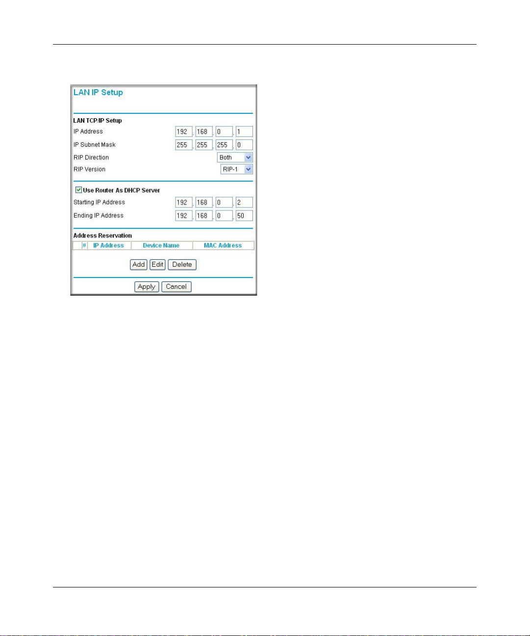
Reference Manual for the Double 108 Mbps Wireless Firewall Router WGU624
Figure 7-4: LAN IP Setup Menu
The LAN IP parameters are:
IP Address: This is the LAN IP address of the router.
IP Subnet Mask: This is the LAN Subnet Mask of the router. Combined with the IP address, the
IP Subnet Mask allows a device to know which other addresses are local to it, and which must be
reached through a gateway or router .
RIP Direction: RIP (Router Information Protocol) allows a router to exchange routing
information with other routers. The RIP Direction selection controls how the router sends and
receives RIP packets. Both is the default.
• When set to Both or Out Only, the router will broadcast its routing table periodically.
• When set to Both or In Only, it will incorporate the RIP information that it receives.
• When set to None, it will not send any RIP packets and will ignore any RIP packets
received.
Advanced Configuration 7-9
M-10153-01
Page 88

Reference Manual for the Double 108 Mbps Wireless Firewall Router WGU624
RIP Version: This controls the format and the broadcasting method of the RIP packets that the
router sends. (It recognizes both formats when receiving.) By default, this is set for RIP-1.
• RIP-1 is universally supported. RIP-1 is probably adequate for most networks, unless you
have an unusual network setup.
• RIP-2 carries more information. Both RIP-2B and RIP-2M send the routing data in RIP-2
format.
• RIP-2B uses subnet broadcasting.
• RIP-2M uses multicasting. Multicasting can reduce the load on non-router machines
because they do not listen to the RIP multicast address and will not receive the RIP
packets. However, if one router uses multicasting, then all routers on your network
must use multicasting.
Note: If you change the LAN IP address of the router while connected through the
browser, you will be disconnected. You may need to restart your computer for the new
IP address setting to take effect.
Using the Router as a DHCP Server
By default, the router will function as a DHCP (Dynamic Host Configuration Protocol) server,
allowing it to assign IP, DNS server, and default gateway addresses to all computers connected to
the router's LAN. The assigned default gateway address is the LAN address of the router. IP
addresses will be assigned to the attached PCs from a pool of addresses specified in this menu.
Each pool address is tested before it is assigned to avoid duplicate addresses on the LAN.
For most applications, the default DHCP and TCP/IP settings of the router are satisfactory. See “IP
Configuration by DHCP” on page B-10 for an explanation of DHCP and information about how to
assign IP addresses for your network.
If another device on your network is the DHCP server, or if you will manually configure the
network settings of all of your computers, clear the ‘Use router as DHCP server’ check box.
Otherwise, leave it selected.
Specify the pool of IP addresses to be assigned by setting the Starting IP Address and Ending IP
Address. These addresses should be part of the same IP address subnet as the router’s LAN IP
address. Using the default addressing scheme, you should define a range between 192.168.1.2 and
192.168.1.253, although you may wish to save part of the range for device s with fixed addresses.
7-10 Advanced Configuration
M-10153-01
Page 89

Reference Manual for the Double 108 Mbps Wireless Firewall Router WGU624
The router delivers the following parameters to any LAN device that requests DHCP:
• An IP Address from the range you have defined
• Subnet Mask
• Gateway IP Address (the router’s LAN IP address)
• Primary DNS Server (if you entered a Primary DNS address in the Basic Settings menu;
otherwise, the router’s LAN IP address)
• Secondary DNS Server (if you entered a Secondary DNS address in the Basic Settings menu
Using Address Reservation
When you specify a reserved IP address for a PC on the LAN, that PC always receives the same IP
address each time it accesses the router’s DHCP server. Reserved IP addresses should be assigned
to servers that require permanent IP settings.
To res erve an IP address:
1. Click the Add button.
2. In the IP Address box, type the IP address to assign to the PC or server (choose an IP address
from the router’s LAN subnet, such as 192.168.1.X).
3. Type the MAC Address of the PC or server.
Tip: If the PC is already present on your network, you can copy its MAC address from the
Attached Devices menu and paste it here.
4. Click Apply to enter the reserved address into the table.
Note: The reserved address will not be assigned until the next time the PC contacts the router’s
DHCP server. Reboot the PC or access its IP configuration and force a DHCP release and renew.
To edit or delete a res erved address entry:
1. Click the button next to the reserved address you want to edit or delete.
2. Click Edit or Delete.
Advanced Configuration 7-11
M-10153-01
Page 90

Reference Manual for the Double 108 Mbps Wireless Firewall Router WGU624
Using a Dynamic DNS Service
If your network has a permanently assigned IP address, you can register a domain name and have
that name linked with your IP address by public Domain Name Servers (DNS). However, if your
Internet account uses a dynamically assigned IP address, you will not know in advance what your
IP address will be, and the address can change frequently. In this case, you can use a commercial
dynamic DNS service which will allow you to register your domain to their IP address, and will
forward traffic directed at your domain to whatever your current IP address happens to be.
Note: If your ISP assigns a private WAN IP address (such as 192.168.x.x or 10.x.x.x),
the dynamic DNS service will not work because private addresses will not be routed on
the Internet.
The router contains a client that can connect to many popular dynamic DNS services. You can
select one of these services and obtain an account with them. Then, whenever your ISP-assigned
IP address changes, your router will automatically contact your dynamic DNS service provider,
log in to your account, and register your new IP address.
From the main menu of the browser interface, under Advanced, click Dynamic DNS.
Figure 7-5: Dynamic DNS menu
7-12 Advanced Configuration
M-10153-01
Page 91

Reference Manual for the Double 108 Mbps Wireless Firewall Router WGU624
To configure Dynamic DNS:
1. Register for an account with DynDNS.org. Select “Click here for information” to go to
www.dyndns.org.
2. Select DynDNS.org.
3. Type the Host Name appended with dyndns.org. For example:
myHostName.dyndns.org
4. Type the User Na me for your dynamic DNS account.
5. Type the Password (or key) for your dynamic DNS account.
6. If you want to allow the use of wildcards in resolving your URL, you can select the Use
wildcards check box to activate this feature. For example, the wildcard feature will cause
*.yourhost.dyndns.org to be aliased to the same IP address as yourhost.dyndns.org
7. Click Apply to save your configuration.
Configuring Static Routes
Static Routes provide additional routing information to your router. Under normal circumstances,
the router has adequate routing information after it has been configured for Internet access, and
you do not need to configure additional static routes. You must configure static routes only for
unusual cases such as multiple routers or multiple IP subnets located on your network.
From the main menu of the browser interface, under Advanced, select Static Routes to view the
Static Routes menu, shown below.
Figure 7-6. Static Routes menu
Advanced Configuration 7-13
M-10153-01
Page 92

Reference Manual for the Double 108 Mbps Wireless Firewall Router WGU624
To add or edit a Static Route:
1. Click the Add button to open the Add/Edit menu, shown below.
Figure 7-7. Static Route Add/Edit menu
2.
Type a route name for this static route in the Route Name box under the table. (This is for
identification purposes only.)
3. Select Private if you want to limit access to the LAN only. The static route will not be reported
in RIP.
4. Select Active to make this route effective.
5. Type the Destination IP Address of the final destination.
6. Type the IP Subnet Ma sk for this destination. If the destination is a single host, type
255.255.255.255.
7. T ype the Gateway IP Address, which must be a router on the same LAN segment as the router.
8. Type a number between 1 and 15 as the Metric value. This represents the number of routers
between your network and the destination. Usually, a setting of 2 or 3 works, but if this is a
direct connection, set it to 1.
9. Click Apply to have the static route entered into the table.
7-14 Advanced Configuration
M-10153-01
Page 93

Reference Manual for the Double 108 Mbps Wireless Firewall Router WGU624
Static Route Example
As an example of when a static route is needed, consider the following case:
• Your primary Internet access is through a cable modem to an ISP.
• You have an ISDN router on your home network for connecting to the company where
you are employed. This router’s address on your LAN is 192.168.1.100.
• Your company’s network is 134.177.1.0.
When you first configured your router, two implicit static routes were created. A default route was
created with your ISP as the gateway, and a second static route was created to your local network
for all 192.168.1.x addresses. With this configuration, if you attempt to access a device on the
134.177.1.0 network, your router forwards your request to the ISP. The ISP forwards your request
to the company where you are employed, and the request will likely be denied by the company’s
firewall.
In this case you must define a static route, telling your router that 134.177.1.0 should be accessed
through the ISDN router at 192.168.1.100. The static route would look like Figure 7-7.
In this example:
• The Destination IP Address and IP Subnet Mask fields specify that this static route applies to
all 134.177.1.x addresses.
• The Gateway IP Address fields specifies that all traffic for these addresses should be
forwarded to the ISDN router at 192.168.1.100.
• A Metric value of 1 will work since the ISDN router is on the LAN.
• Private is selected only as a precautionary security measure in case RIP is activated.
Advanced Configuration 7-15
M-10153-01
Page 94

Reference Manual for the Double 108 Mbps Wireless Firewall Router WGU624
Enabling Remote Management Access
Using the Remote Management page, you can allow a user or users on the Internet to configure,
upgrade and check the status of your WGU624 wireless router.
Note: Be sure to change the router's default configuration password to a very secure
password. The ideal password should contain no dictionary words from any language,
and should be a mixture of letters (both upper and lower case), numbers, and symbols.
Your password can be up to 30 characters.
To configure your router for Remote Management:
1. Select the Turn Remote Management On check box.
2. Specify what external addresses will be allowed to access the router’s remote management.
Note: For enhanced security, restrict access to as few external IP addresses as practical.
• To allow access from any IP address on the Internet, select Everyone.
• To allow access from a range of IP addresses on the Internet, select IP address range.
Enter a beginning and ending IP address to define the allowed range.
• To allow access from a single IP address on the Internet, select Only this PC.
Enter the IP address that will be allowed access.
3. Specify the Port Number that will be used for accessing the management interface.
Web browser access norma lly uses the standard HTTP service port 80. For greater security,
you can change the remote management Web interface to a custom port by entering that
number in the box provided. Choose a number between 1024 and 65535, but do not use the
number of any common service port. The default is 8080, which is a common alternate for
HTTP.
4. Click Apply to have your changes take effect.
Note: When accessing your router from the Internet, you will type your router's WAN IP address
into your browser's Address (in IE) or Location (in Netscape) bo x, follo wed by a colo n (:) an d the
custom port number. For example, if your external address is 134.177.0.123 and you use port
number 8080, you must enter http://134.177.0.123:8080 in your browser.
7-16 Advanced Configuration
M-10153-01
Page 95

Reference Manual for the Double 108 Mbps Wireless Firewall Router WGU624
Using Universal Plug and Play (UPnP)
Universal Plug and Play (UPnP) helps devices, such as Internet appliances and computers,
access the network and connect to other devices as needed. UPnP devices can
automatically discover the services from other registered UPnP devices on the network.
Figure 7-8. UPnP Menu
Turn UPnP On: UPnP can be enabled or disabled for automatic device configuration. The default
setting for UPnP is enabled. If disabled, the router will not allow any device to automatically
control the resources, such as port forwarding (mapping), of the router.
Advertisement Period: The Advertisement Period is how often the router will broadcast its UPnP
information. This value can range from 1 to 1440 minutes. The default period is 30 minutes.
Shorter durations will ensure that control points have current device status at the expense of
additional network traffic. Longer durations may compromise the freshness of the device status
but can significantly reduce network traffic.
Advertisement Time To Live: The time to live for the advertisement is measured in hops (steps)
for each UPnP packet sent. The time to live hop count is the number of steps a broadcast packet is
allowed to propagate for each UPnP advertisement before it disappears. The number of hops can
range from 1 to 255. The default value for the advertisement time to live is 4 hops, which should
be fine for most home networks. If you notice that some devices are not being updated or reached
correctly, then it may be necessary to increase this value a little.
Advanced Configuration 7-17
M-10153-01
Page 96

Reference Manual for the Double 108 Mbps Wireless Firewall Router WGU624
UPnP Portmap Table: The UPnP Portmap Table displays the IP address of each UPnP device
that is currently accessing the router and which ports (Internal and External) that device has
opened. The UPnP Portmap Table also displays what type of port is opened and if that port is still
active for each IP address.
7-18 Advanced Configuration
M-10153-01
Page 97

Chapter 8
Troubleshooting
This chapter gives information about troubleshooting your Double 108 Mbps Wireless Firewall
Router WGU624. After each problem description, instructions are provided to help you diagnose
and solve the problem.
Note: Product updates are available on the NETGEAR, Inc. Web site at
http://kbserver.netgear.com/products/WGU624.asp.
Basic Functioning
After you turn on power to the router, the following sequence of events should occur:
1. When power is first applied, verify that the Power LED is on.
2. After approximately 10 seconds, verify that:
a. The Local port LEDs are lit for any local ports that are connected.
If a port’s LED is lit, a link has been established to the connected device. If a LAN port is
connected to a 100 Mbps device, verify that the port’s LED is green. If the port is 10
Mbps, the LED will be amber.
b. The Wireless A port LED is lit.
c. The Wireless G port LED is lit.
d. The Internet port LED is lit.
If any of these conditions does not occur, refer to the appropriate following section.
Troubleshooting 8-1
M-10153-01
Page 98

Reference Manual for the Double 108 Mbps Wireless Firewall Router WGU624
Power LED Not On
If the Power and other LEDs are off when your router is turned on:
• Make sure that the power cord is properly connected to your router and that the power supply
adapter is properly connected to a functioning power outlet.
• Check that you are using the 12 V DC 800mA power adapter supplied by NETGEAR for this
product.
If the error persists, you have a hardware problem and should contact technical support.
LEDs Never Turn Off
When the router is turned on, the LEDs turns on for about 10 seconds and then turn off. If all the
LEDs stay on, there is a fault within the router.
If all LEDs are still on one minute after power up:
• Cycle the power to see if the router recovers.
• Clear the router’s configuration to factory defaults. This sets the router’s IP address to
192.168.1.1. This procedure is explained in “Restoring the Default Configuration and
Password” on page 8-7.
If the error persists, you might have a hardware problem and should contact technical support.
Local or Internet Port LEDs Not On
If either the LAN LEDs or WAN LED do not light when the Ethernet connection is made, check
the following:
• Make sure that the Ethernet cable connections are secure at the router and at the hub or
workstation.
• Make sure that power is turned on to the connected hub or workstation.
• Be sure you are using the correct cable:
When connecting the router’s WAN port to a cable or DSL modem, use the cable that was
supplied with the cable or DSL modem. This cable could be a standard straight-through
Ethernet cable or an Ethernet crossover cable.
8-2 Troubleshooting
M-10153-01
Page 99

Reference Manual for the Double 108 Mbps Wireless Firewall Router WGU624
Troubleshooting the Web Configuration Interface
If you are unable to access the router’s Web Configuration interface from a PC on your local
network, check the following:
• Check the Ethernet connection between the PC and the router as described in the previous
section.
• Make sure your PC’s IP address is on the same subnet as the router. If you are using the
recommended addressing scheme, your PC’s address should be in the range of 192.168.1.2 to
192.168.1.254. Refer to “Verifying TCP/IP Properties” on page C-6 or “Verifying TCP/IP
Properties for Macintosh Computers” on page C-17 to find your PC’s IP address. Follow the
instructions in Appendix C to configure your PC.
Note: If your PC’s IP address is shown as 169.254.x.x, recent versions of Windows and
MacOS will generate and assign an IP address if the computer cannot reach a DHCP server.
These auto-generated addresses are in the range of 169.254.x.x. If your IP address is in this
range, check the connection from the PC to the router and reboot your PC.
• If your router’s IP address has been changed and you do not know the current IP address, clear
the router’s configuration to factory defaults. This will set the router’s IP address to
192.168.1.1. This procedure is explained in “Restoring the Default Configuration and
Password” on page 8-7.
• Make sure your browser has Java, JavaScript, or ActiveX enabled. If you are using Internet
Explorer, click Refresh to be sure the Java applet is loaded.
• Try quitting the browser and launching it again.
• Make sure you are using the correct login information. The factory default login name is
admin and the password is password. Make sure that CAPS LOCK is off when entering this
information.
If the router does not save changes you have made in the Web Configuration Interface, check the
following:
• When entering configuration settings, be sure to click the Apply button before moving to
another menu or tab, or your changes will be lost.
• Click the Refresh or Reload button in the Web browser. The changes may have occurred, but
the Web browser may be caching the old configuration.
Troubleshooting 8-3
M-10153-01
Page 100

Reference Manual for the Double 108 Mbps Wireless Firewall Router WGU624
Troubleshooting the ISP Connection
If your router is unable to access the Internet, you should first determine whether the router is able
to obtain a WAN IP address from the ISP. Unless you have been assigned a static IP address, your
router must request an IP address from the ISP. You can determine whether the request was
successful using the Web Configura tion Manager.
To check the WAN IP address:
1. Launch your browser and select an external site such as http://ww.netgear.com.
2. Access the main menu of the router’s configuration at http://192.168.1.1.
3. Under the Maintenance heading, select Router Status.
4. Check that an IP address is shown for the WAN Port.
If 0.0.0.0 is shown, your router has not obtained an IP address from your ISP.
If your router is unable to obtain an IP address from the ISP, you may need to force your cable or
DSL modem to recognize your new router by performing the following procedure:
1. Turn off power to the cable or DSL modem.
2. Turn off power to your router.
3. Wait five minutes and reapply power to the cable or DSL modem.
4. When the modem’s LEDs indicate that it has reacquired synchronizatio n with the ISP, reapply
power to your router.
If your router is still unable to obtain an IP address from the ISP, the problem may be one of the
following:
• Your ISP may require a login program.
Ask your ISP whether they require PPP over Ethernet (PPPoE) or some other type of login.
• If your ISP requires a login, you may have incorrectly set the login name and password.
• Your ISP may check for your PC's host name.
Assign the PC Host Name of your ISP account as the Account Name in the Basic Settings
menu.
• Your ISP only allows one Ethernet MAC address to connect to Internet, and may check for
your PC’s MAC address. In this case:
Inform your ISP that you have bought a new network device, and ask them to use the router’s
MAC address.
8-4 Troubleshooting
M-10153-01
 Loading...