

Page 1
Reference Manual for the
WG302 802.11g ProSafe
Wireless Access Point
NETGEAR, Inc.
4500 Great America Parkway
Santa Clara, CA 95054 USA
Phone 1-888-NETGEAR
August 2003
December 2003
Page 2

NETGEAR, INC.
www.NETGEAR.com
Technical Support
Please register to obtain technical support. Please retain your proof of purchase and warranty
information.
To register your product, get product support or obtain product information and product
documentation, go to http://www.NETGEAR.com
Web, you may register your product by filling out the registration card and mailing it to
NETGEAR customer service.
You will find technical support information at:
http://www.NETGEAR.com/
through the customer service area. If you want to contact technical
support by telephone, see the support information card for the correct telephone number for your
country.
© 2003 by NETGEAR, Inc. All rights reserved.
Trademarks
. If you do not have access to the World Wide
NETGEAR is a registered trademark of NETGEAR, INC. Windows is a registered trademark of Microsoft
Corporation. Other brand and product names are trademarks or registered trademarks of their respective
holders. Information is subject to change without notice. All rights reserved.
Federal Communications Commission (FCC) Compliance Notice: Radio Frequency Notice
WG302 802.11g ProSafe Wireless Access Point
Tested to Comply
with FCC Standards
FOR HOME OR OFFICE USE
FCC ID: PY3WG302
This device complies with part 15 of the FCC Rules. Operation is subject to the following two conditions:
1. This device may not cause harmful interference.
2
December 2003
Warning!
To co mply with the FCC’s of exposure
requirements you must maintain a distance of at
least 1 cm from the antenna of this device while
it is in use. This device should not be co-located
with other transmitters.
Page 3

2. This device must accept any interference received, including interference that may cause undesired
operation.
Note: This equipment has been tested and found to comply with the limits for a Class B digital device,
pursuant to part 15 of the FCC Rules. These limits are desig ned to provi de reasonable protection
against harmful interference in a residential installation. This equipment generates, uses, and can
radiate radio frequency energy and, if not installed and used in accordance with the instructions,
may cause harmful interference to radio communications. However, there is no guarantee that
interference will not occur in a particular installation. If this equipment does cause harmful
interference to radio or television reception, which can be determined by turning the equipment off
and on, the user is encouraged to try to correct the interference by one or more of the following
measures:
• Reorient or relocate the receiving antenna
• Increase the separation between the equipment and receiver
• Connect the equipment into an outlet on a circuit different from that to which the receiver is
connected
• Consult the dealer or an experienced radio/TV technician for help.
Placement and Range Guidelines
Indoors, computers can connect over 802.11 wireless networks at a maximum range of 500 feet (152.4 m)
for 802.11b devices. However, the operating distance or range of your wireless connection can vary
significantly, based on the physical placement of the wireless access point.
For best results, identify a location for your wireless access point according to these guidelines:
• Away from potential sources of interference , such as PCs, large metal surfaces, microwaves, and 2.4 GHz cordless
phones.
• In an elevated location such as a high shelf that is near the center of the wireless coverage area for all mobile
devices.
Failure to follow these guidelines can result in significant performance degradation or inability to wirelessly
connect to the wireless access point.
To meet FCC and other nat ional safety guideli nes for rf exposure, the antennas for this device must be
installed to ensure a minimum separation distance of 20cm (7.9 in.) from persons. Further, the antennas shall
not be co-located with other transmitting structures.
Statement of Conditions
In the interest of improving internal design, operational function, and/or reliability, NETGEAR reserves the
right to make changes to the products described in this document without notice. NETGEAR does not
assume any liability that may occur due to the use or application of the product(s) or circuit layout(s)
described herein.
Modifications made to the product, unless expressly approved by Netgear, could void the user’s authority to
operate the equipment. NETGEAR does not assume any liability that may occur due to such condition.
December 2003
3
Page 4

FCC Statement
DECLARATION OF CONFORMITY
We Netgear,
4500 Great America Parkway
Santa Clara, CA 95054, USA
Tel: +1 408 907 8000
declare under our sole responsibility that the product(s)
WG302 (Model Designation)
802.11g Pr oSafe Wireless Access Point (Product Name)
complies(y) with Part 15 of FCC Rules.
Operation is subject to the following two conditions: (1) this device may not cause harmful
interference, and (2) this device must accept any interference received, including interference that
may cause undesired operation.
NOTE: This equipment has been tested and found to comply with the limits for a Class B digital device,
pursuant to Part 15 of the FCC Rules. These limits are designed to provide reasonable protection against
harmful interference in a residential installation. This equipment generates, uses, and can radiate radio
frequency energy and, if not installed and used in accordance with the instructions, may cause harmful
interference to radio communications. However, there is no guarantee that interference will not occur in a
particular installation. If this equipment does cause harmful interference to radio or television reception,
which can be determined by turning the equipment off and on, the user is encouraged to try and correct the
interference by one or more of the following measures:
4
December 2003
Page 5

• Reorient or locate the receiving antenna.
• Increase the separation between the equipment and receiver.
• Connect the equipment into an outlet on a circuit different from that to which the receiver is connected.
• Consult the dealer or an experienced radio/TV technician for help.
RF Exposure Wa rning for North America, and Australia
W arning! To meet FCC and other national safety guidelines for rf exposure, the antennas for this device (see
below) must be installed to ensure a minimum separation distance of 20cm (7.9 in.) from persons. Furth e r,
the antennas shall not be co-located with other antenna or radio transmitter.
Antenna Statement for North America and Australia
In addition to its own 2 antennas, the WG302 device has been approved for use with the following
detachable antennas and antenna cables:
Approved
Antennas
NETGEAR
ANT24D18
NETGEAR
ANT2409
NETGEAR
ANT24O5
Antenna Gain and
type
18 dBi, directional
outdoor/indoor
9 dBi, omnidirectional
outdoor/indoor
5 dBi, ceiling/wall
indoor
Approved Antenna
Cable
NETGEAR
ACC-10314-01 thru
05
NETGEAR
ACC-10314-01 thru
05
NETGEAR
ACC-10314-01 thru
05
Antenna Cable
Length
1.5 m to 30 m 19 dBm + 18 dBi ant.
1.5 m to 30 m 19 dBm + 9 dBi ant.
1.5 m to 30 m 19 dBm + 5 dBi ant.
Maximum
Transmitted Power
* WG302 maximum radiated power in North America and Australia: 20 dBm – cable loss + antenna gain
Please go to www.netgear.com/go-fcc…. for an updated list of wireless accessories approved to be used with
the WG302 in North America and Australia.
Industry Canada Compliance Statement
This Class B Digital apparatus meets all the requirements of the Canadian Interference Causing
Equipment Regulations ICES 003.
Cet appareil numerique de classe B respecte les exigences du reglement du Canada sur le materiel
brouilleur NMB-003.
The device is certified to the requirements of RSS-210 for 2.4 GHz spread spectrum devices. The
use of this device in a system operating either partially or completely outdoors may require the
user to obtain a license for the system according to the Canadian regulations. For further
December 2003
5
Page 6

information, contact your local Industry Canada office.
6
December 2003
Page 7

Contents
RF Exposure Warning for North America, and Australia ..........................................1-5
Chapter 1
About This Manual
Audience, Versions, Conventions ...................................................................................1-v
How to Use this Manual ................................................................................................. 1-vi
How to Print this Manual ............................................................................................... 1-vii
Chapter 2
Introduction
About the WG302 802.11g ProSafe Wireless Access Point ...........................................2-1
Key Features ..................................................................................................................2-2
802.11g Standards-based Wireless Networking ......................................................2-3
Autosensing Ethernet Connections with Auto Uplink ...............................................2-3
Compatible and Related NETGEAR Products .........................................................2-4
System Requirements ....................................................................................................2-4
What’s In the Box? .........................................................................................................2-4
Hardware Description .....................................................................................................2-5
WG302 Wireless Access Point Front Panel .............................................................2-5
WG302 Wireless Access Point Rear Panel .............................................................2-7
Left and Right Detachable Antenna ...................................................................2-7
Restore to Factory Defaults Button ....................................................................2-7
Serial Port ..........................................................................................................2-7
RJ-45 Ethernet Port ...........................................................................................2-7
Power Socket ....................................................................................................2-7
Chapter 3
Basic Installation and Configuration
Observing Placement and Range Guidelines ..................... ................ ................ ............3-1
Cabling Requirements ..............................................................................................3-2
Default Factory Settings ...........................................................................................3-3
Understanding WG302 Wireless Security Options ................................. ........................ 3-4
Installing the WG302 802.11g ProSafe Wireless Access Point ......................................3-5
How to Log In to the WG302 Using Its Default IP Address ............................................3-8
Contents iii
December 2003
Page 8

Understanding Basic Wireless Settings .............................. .......................... ..................3-9
Understanding Basic Wireless Security Options ..........................................................3-11
Information to Gather Before Changing Basic Wireless Settings ...........................3-13
How to Set Up and Test Basic Wireless Connectivity ............................................ 3-14
How to Restrict Wireless Access by MAC Address ...............................................3-15
How to Configure WEP ..........................................................................................3-16
Using the Basic IP Settings Options .............................................................................3-17
Chapter 4
Management
Using the Secure Telnet Interface ...................................................... .... ... ... ... ... .... ... ... ..4-1
How to Use the CLI via the Console Port: ................................................................4-1
CLI Commands ........................................................................................................4-2
Viewing General, Log, Station, and Statistical Information .............................................4-5
Statistics ................................................................. .................................................. 4-7
Viewing a List of Attached Devices .................................................................................4-9
Upgrading the Wireless Access Point Software ...........................................................4-10
Configuration File Management ...................................................................................4-11
Saving and Retrieving the Configuration ................................................................4-11
Restoring the WG302 to the Factory Default Settings ...........................................4-12
Using the Reset Button to Restore Factory Default Settings ................. ... ... .... ... ...4-12
Changing the Administrator Password ......................... ....................................... ... 4-13
Chapter 5
Advanced Configuration
Understanding Advanced Wireless Settings ..................................................................5-1
Configuring Wireless Operating Modes ........................... ............................................... 5-2
How to Configure a WG302 as a Point-to-Point Bridge ...........................................5-3
How to Configure Multi-Point Wireless Bridging ......................................................5-4
How to Configure Wireless Repeating .....................................................................5-5
Chapter 6
Troubleshooting
No lights are lit on the access point. ...................................... ......................................... 6-1
The Wireless LAN activity light does not light up. ...........................................................6-2
The LAN light is not lit. ....................................................................................................6-2
I cannot access the Internet or the LAN with a wireless capable computer. .................6-2
I cannot connect to the WG302 to configure it. ..............................................................6-3
iv Contents
December 2003
Page 9

When I enter a URL or IP address I get a timeout error. ........................................ ... ... ..6-3
Using the Reset Button to Restore Factory Default Settings . .... ... ... ... .... ... ... ... ... .... ... ... ..6-3
Appendix A
Specifications
Specifications for the WG302 ........................................................................................ A-1
Appendix B
Wireless Networking Basics
Wireless Networking Overview ..................................... ... ... ........................................... B-1
Infrastructure Mode ................................................................................................. B-1
Ad Hoc Mode (Peer-to-Peer Workgroup) ..................................... .... ... ... ... ... .... ....... B-2
Network Name: Extended Service Set Identification (ESSID) ................................ B-2
Authentication, WEP, and WPA ..................................................................................... B-2
802.11 Authentication .............................................................................................. B-3
Open System Authentication .............................. .... ... ... ... .... ... ... ... .... ....................... B-3
Shared Key Authentication ...................................................................................... B-4
Overview of WEP Parameters ................................................................................ B-5
Key Size .................................................................................................................. B-6
WEP Configuration Options ...................................... ... ... .... ... ... ... .... ... ... ... ... .... ... ... . B-7
Wireless Channels ....................... .... ... ... ... ..................................................................... B-7
Glossary
Index
Contents v
December 2003
Page 10

vi Contents
December 2003
Page 11
Reference Manual for the WG302 802.11g ProSafe Wireless Access Point
Chapter 1
About This Manual
Congratulations on your purchase of the WG302 802.11g ProSafe Wireless Access Point. The
WG302 provides connection for multiple personal computers to the Internet through an external
broadband access device (such as a cable modem or DSL mo dem).
Audience, Versions, Conventions
This reference manual assumes that the reader has basic to intermediate computer and Internet
skills. However, basic co mputer network, Internet, and firewall technologies tutorial information is
provided in the Appendices and on the NETGEAR Web site.
This guide uses the following formats to highlight special messages:
Note: This format is used to highlight information of importance or special interest.
This manual is written for the WG302 Access Point according to these versions.:
Table 1-1. Product, Firmware Version, Manual Version, and Publication Date
Product WG302 802.11g ProSafe Wireless Access Point
Manual Part Number
Manual Publication Date August 2003
Note: Product updates are available on the NETGEAR web site at
www.netgear.com/support/main.asp. Documentation updates are available on the
NETGEAR, Inc. web site at www.netgear.com/docs.
About This Manual 1-v
December 2003
Page 12
Reference Manual for the WG302 802.11g ProSafe Wireless Access Point
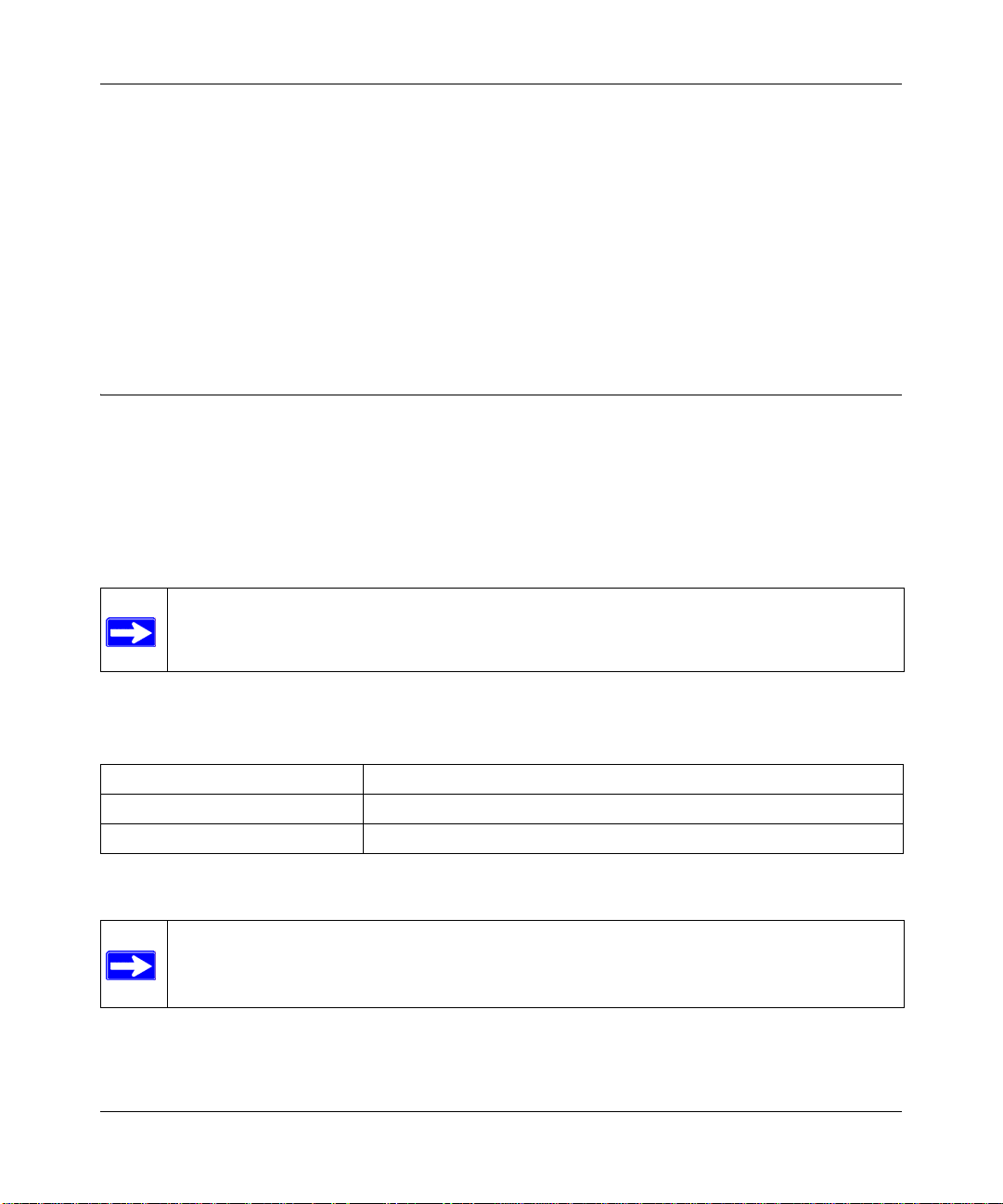
How to Use this Manual
The HTML version of this manual includes a variety of navigation features as well as links to PDF
versions of the full manual and individual chapters.
1
2
3
Figure 1-1: HTML version of this manual
1. Left Pane. Use the left pane to view the Contents, Index, Search, and Favorites tabs.
To view the HT ML version of the manual, you must have a version 4 or later browser with
JavaScript enabled.
2. Toolbar Buttons. Use the toolbar buttons across the top to navigate, print pages, and more.
The Show in Contents button locates the current topic in the Contents tab.
Previous/Next buttons display the previous or next topic.
The PDF button links to a PDF version of the full manual.
The Print button prints the current topic. Using this button when a
step-by-step procedure is displayed will send the entire procedure to your
printer–you do not have to worry about specifying the correct range of pages.
3. Right Pane. Use the right pane to view the contents of the manual. Also, each page of the
manual includes a link at the top right which links to a PDF file
containing just the currently selected chapter of the manual.
1-vi About This Manual
December 2003
Page 13
Reference Manual for the WG302 802.11g ProSafe Wireless Access Point
How to Print this Manual
To print this manual, choose one of the following options.
• Printing a “How To” Sequence of Steps in the HTML View. Use the Print button on
the upper right of the toolbar to print the currently displayed topic. Using this button when a
step-by-step procedure is displayed will send the entire procedure to your printer–you do not
have to worry about specifying the correct range of pages.
• Printing a Chapter. Use the link at the top right of any page.
– Click “PDF of This Chapter” link at the top right of any page in the chapter you want to
print. The PDF version of the chapter you were viewing opens in a browser window.
Note: Your computer must have the free Adobe Acrobat reader installed in order to view
and print PDF files. The Acrobat reader is available on the Adobe Web site at
http://www.adobe.com.
– Click the print icon in the upper left of the window.
Tip: If your printer supports printing two pages on a single sheet of paper, you can save
paper and printer ink by selecting this feature.
• Printing the Full Manual. Use the PDF button in the toolbar at the top right of the browser
window.
– Click the PDF button on the upper right of the toolbar. The PDF version of the
chapter you were viewing opens in a browser window.
– Click the print icon in the upper left of the window.
Tip: If your printer supports printing two pages on a single sheet of paper, you can save
paper and printer ink by selecting this feature.
About This Manual 1-vii
December 2003
Page 14

Reference Manual for the WG302 802.11g ProSafe Wireless Access Point
1-viii About This Manual
December 2003
Page 15

Chapter 2
Introduction
This chapter introduces the NETGEAR WG302 802.11g ProSafe Wireless Access Point. Minimal
prerequisites for installation are presented in “System Requirements” on page 2-4.
About the WG302 802.11g ProSafe Wireless Access Point
The WG302 802.11g ProSafe W ireless Access Point is the basic building block of a wireless LAN
infrastructure. It provides connectivity between Ethernet wired networks and radio-equipped
wireless notebook systems, desktop systems, print servers, and other devices.
The WG302 provides wireless connectivity to multiple wireless network devices within a fixed
range or area of coverage, interacting with a wireless network interface card (NIC) via an antenna.
T ypically, an individual in-building access point provides a maximum connectivity area with about
a 300 foot radius. The WG302 802.11g ProSafe Wireless Access Point can support a small group
of users in a range of several hundred feet. Most access points are rated between 30-70 users
simultaneously.
The WG302 802.11g ProSafe Wi reless Access Point acts as a bridge between the wired LAN and
wireless clients. Connecting multiple WG302 Access Points via a wired Ethernet backbone can
further lengthen the wireless network coverage. As a mobile computing device moves out of the
range of one access point, it moves into the range of another. As a result, wireless clients can freely
roam from one Access Point to another and still maintain seamless connection to the network.
The auto-sensing capability of the WG302 802.11g ProSafe Wireless Access Point allows packet
transmission at up to 108 Mbps, or at reduced speeds to compensate for distance or
electromagnetic noise interference.
Introduction 2-1
December 2003
Page 16

Reference Manual for the WG302 802.11g ProSafe Wireless Access Point
Key Features
The WG302 Access Point is easy-to-use and provides solid wireless and networking support.
Supported Standards and Conventions
The following standards and conventions are supported:
• Standards Compliant. The Wireless Access Point complies with the IEEE 802.11g for
Wireless LANs.
• WEP support. Support for WEP is included. Both 64-bit, 128-bit, and 152-bit keys are
supported.
• DHCP Client Support. DHCP provides a dynamic IP address to PCs and other devices upon
request. The WG302 can act as a client and obtain information from your DHPC server.
• SNMP Support. Support for Simple Network Management Protocol (SNMP) Management
Information Base (MIB) management.
Key Features
The NETGEAR WG302 provides solid functionality, including these features:
• Multiple Operating Modes
– Wireless Access Point. Operates as a standard 802.11g.
– Point-to-Point Bridge. In this mode, the WG302 only communicates with another
bridge-mode wireless station. You must enter the MAC address (physical address) of the
other bridge-mode wireless station in the field provided. WEP should be used to protect
this communication.
– Point-to-Multi-Point Bridge. Select this only if this WG302 is the “Master” for a group
of bridge-mode wireless stations. The other bridge-mode wireless stations must be set to
Point-to-Point Bridge mode, using this WG302's MAC address. They then send all traffic
to this “Master”, rather than communicate directly with each other . WEP should be used to
protect this traffic.
– Wireless Repeater. In this half-duplex mode, the WG302 only communicates with
another repeater-mode wireless station. You must enter the MAC address (physical
address) of the both adjacent repeater-mode wireless stations in the fields provided. WEP
should be used to protect this communication.
• Upgradeable Firmware. Firmware is stored in a flash memory and can be upgraded easily,
using only your Web browser, and can be upgraded remotely.
• Access Control. The Access Control MAC address filtering feature can ensure that only
trusted wireless stations can use the WG302 to gain access to your LAN.
2-2 Introduction
December 2003
Page 17

Reference Manual for the WG302 802.11g ProSafe Wireless Access Point
• Simple Configuration. If the default settings are unsuitable, they are easy to change.
• Hidden Mode. The SSID is not broadcast, assuring only clients configured with the correct
SSID can connect.
• Secure Telnet Command Line Interface. The Telnet command line interface enables direct
access over the serial port and easy scripting of configuration of multiple WG302 across an
extensive network via the Ethernet interface. An SSH client is required.
• Configuration Backup. Configuration settings can be backed up to a file and restored.
• Secure and Economical Operation. Adjustable power output allows more secure or
economical operation.
• Power over Ethernet. Power can be supplied to the WG302 over the Ethernet port from any
802.3af compliant mid-span or end-span source such as the NETGEAR FSM7326P Managed
Power over Ethernet Layer 3 managed switch.
• Autosensing Ethernet Connection with
IEEE 802.3 Ethernet networks.
• LED Indicators. Power, test, LAN speed, LAN activity, and wireless activity are easily
identified.
Auto Uplink Interface. Connects to 10/100 Mbps
802.11g Standards-based Wireless Networking
The WG302 802.11g ProSafe Wireless Access Point provides a bridge between Ethernet wired
LANs and 802.11g compatible wireless LAN networks. It provides connectivity between Ethernet
wired networks and radio-equipped wireless notebook systems, desktop systems, print servers, and
other devices. Additionally, the WG302 supports the following wireless features:
• Distributed coordinated function (CSMA/CA, Back off procedure, ACK procedure,
retransmission of unacknowledged frames)
• RTS/CTS handshake
• Beacon generation
• Packet fragmentation and reassembly
• Short or long preamble
• Roaming among access points on the same subnet
Autosensing Ethernet Connections with Auto Uplink
The WG302 can connect to a standard Ethernet network. The LAN interface is autosensing and
capable of full-duplex or half-duplex operation.
Introduction 2-3
December 2003
Page 18

Reference Manual for the WG302 802.11g ProSafe Wireless Access Point
The wireless access point incorporates Auto UplinkTM technology. The Ethernet port will
automatically sense whether the Ethernet cable plugged into the port should have a ‘normal’
connection such as to a PC or an ‘uplink’ connection such as to a switch or hub. That port will then
configure itself to the correct configuration. This feature also eliminates any concerns about
crossover cables, as Auto Uplink will accommodate either type of cable to make the right
connection.
Compatible and Related NETGEAR Products
For a list of compatible products from other manufacturers, see the Wireless Ethernet
Compatibility Alliance Web site (WECA, see http://www.wi-fi.net).
The following NETGEAR products work with the WG302 Access Point:
• WAB501 a/b Dual Band Wireless PC Card Adapter
• MA401 802.11b Wireless PC Card
• WG511 802.11g Wireless CardBus Adapter
• MA111 801.11b Wireless Bridge
• MA101 802.11b Wireless USB Adapter
• ME102 802.11b Wireless Access Point
• MA311 802.11b Wireless PCI Adapter
• MA701 802.11b Wireless Compact Flash Card
System Requirements
Before installing the WG302, make sure your system meets these requirements:
• A 10/100 Mbps Local Area Network device such as a hub or switch
• The Category 5 UTP straight through Ethernet cable with RJ-45 connector included in the
package, or one like it
• A 100-240 V, 50-60 HZ AC power source
• A Web browser for configuration such as Microsoft Internet Explorer 5.0 or above, or
Netscape Navigator 4.78 or above
• At least one computer with the TCP/IP protocol installed
• 802.11b or 802.11b-compliant devices, such as the NETGEAR WG511 Wireless Adapter
What’s In the Box?
The product package should contain the following items:
2-4 Introduction
December 2003
Page 19
Reference Manual for the WG302 802.11g ProSafe Wireless Access Point
• WG302 802.11g ProSafe Wireless Access Point
• Power adapter and cord (12 V dc, 1.2 A)
• Straight through Category 5 Ethernet cable
• WG302 802.11g ProSafe Wireless Access Point Quick Installation Guide (M-10178-01)
• Resource CD for the 802.11g ProSafe Wireless Access Point WG302 (SW-10038-01)
Reference Manual for the WG302 802.11g ProSafe Wireless Ac cess Point ( ) -- this manual
• Support Registration card
Contact your reseller or customer support in your area if there are any wrong, missing, or damaged
parts. You can refer to the Support Information Card for the telephone number of customer support
in your area. You should keep the Support Information card, along with the original packing
materials, and use the packing materials to repack the WG302 if you need to return it for repair. T o
qualify for product updates and product warranty registrations, we encourage you to register on the
NETGEAR Web site at: http://www.NETGEAR.com.
Hardware Description
The WG302 802.11g ProSafe Wi reless Access Point front and rear hardware functions are
described below.
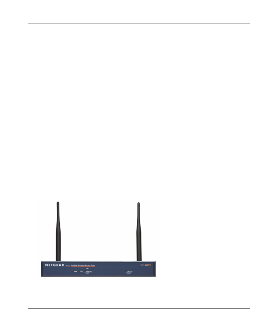
WG302 Wireless Access Point Front Panel
The WG302 Access Point provides four status LEDs.
Figure 2-1: WG302 front panel
Introduction 2-5
December 2003
Page 20

Reference Manual for the WG302 802.11g ProSafe Wireless Access Point
The following table explains the LED indicators:
LED DESCRIPTION
PWR
TEST Self Test Indicator
Blink Indicates self test, loading software, or system fault (if continues).
100 Ethernet LAN Speed Indicator
Green On
LINK/ACT LAN Ethernet LAN Link Activity Indicator
Green On
Green Blink Indicates data traffic on the 100Mbps Ethernet LAN.
Amber 0n 10 Mbps Ethernet link detected, no activity.
Amber Blink Indicates data traffic on the 10Mbps Ethernet LAN.
802.11g WLAN Wireless LAN Link Activity Indicator
Green Blink Wireless link activity.
Power Indicator
No power. If this LED does not come on with the power adapter and cord correctly
Off
installed, see Chapter 4, Troubleshooting.
Power is on.
On
Note: This LED may blink for a minute before going on steady.
Off
Indicates 10 Mbps Ethernet link detected
100 Mbps Fast Ethernet link detected.
Off
Indicates no Ethernet link detected.
100 Mbps Fast Ethernet link detected, no activity.
Off Indicates no wireless link activity.
2-6 Introduction
December 2003
Page 21
Reference Manual for the WG302 802.11g ProSafe Wireless Access Point
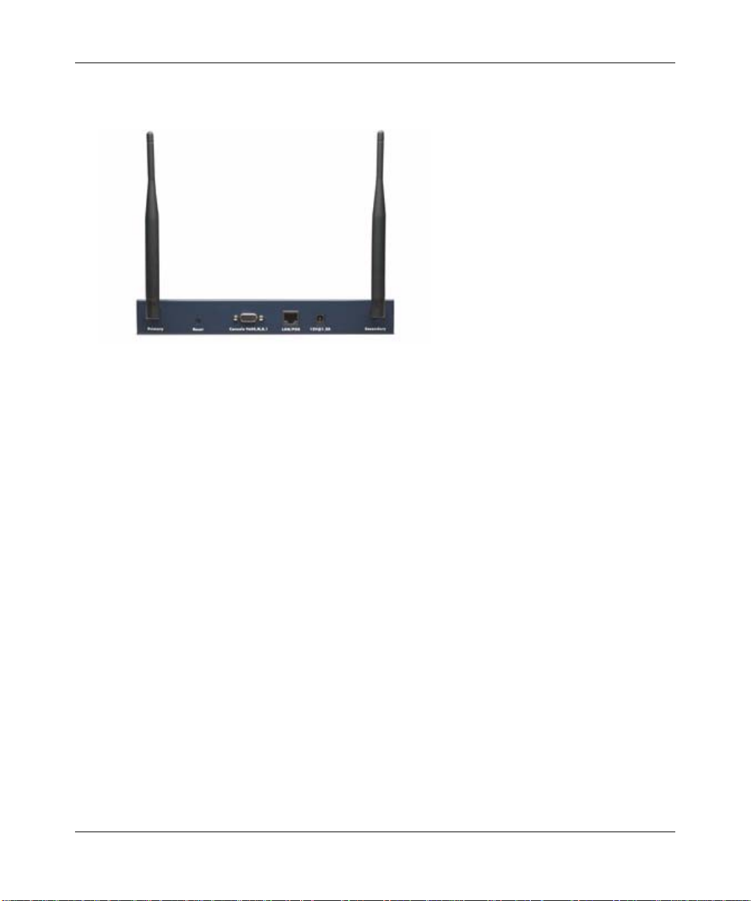
WG302 Wireless Access Point Rear Panel
Figure 2-2: WG302 rear panel
Left and Right Detachable Antenna
The WG302 provides two detachable antenna.
Restore to Factory Defaults Button
The restore to default button located between the Ethernet RJ-45 connector and the power
socket restores the WG302 to the factory default settings.
Serial Port
Male DB-9 serial port for serial connection.
RJ-45 Ethernet Port
Use the WG302 Ethernet RJ-45 port to connect to an Ethernet LAN through a device such as a
hub, switch, router, or POE switch.
Power Socket
This socket connects to the WG302 12V 1.2A power adapter.
Introduction 2-7
December 2003
Page 22
Chapter 3
Basic Installation and Configuration
This chapter describes how to set up your WG302 802.11g ProSafe Wireless Access Point for
wireless connectivity to your LAN. This basic configuration will enable computers with 802.11b
or 802.11g wireless adapters to do such things as connect to the Internet, or access printers and
files on your LAN.
Note: Indoors, computers can connect over 802.11g wireless networks at ranges
of several hundred feet or more. This distance can allow for others outside your area
to access your network. It is important to take appropriate steps to secure your network
from unauthorized access. The WG302 Access Point provides highly effective security
features which are covered in detail in Chapter 3, “Configuring Your Wireless Network.
Deploy the security features appropriate to your needs.
You need to prepare these three things before you can establish a connection through your wireless
access point:
• A location for the WG302 that conforms to the Observing Placement and Range Guidelines
below.
• The wireless access point connected to your LAN through a device such as a hub, switch,
router, or Cable/DSL gateway.
• One or more computers with properly configured 802.11b or 802.11g wireless adapters.
Observing Placement and Range Guidelines
The operating distance or range of your wireless connection can vary significantly bas ed on the
physical placement of the wireless access point. The latency, data throughput performance, and
notebook power consumption of wireless adapters also vary depending on your configuration
choices.
Basic Installation and Configuration 3-1
December 2003
Page 23
Reference Manual for the WG302 802.11g ProSafe Wireless Access Point
Note: Failure to follow these guidelines can result in significant performance
degradation or inability to wirelessly connect to the WG302. For complete performance
specifications, see Appendix A, “Specifications”.
For best results, place your wireless access point:
• Near the center of the area in which your PCs will operate.
• In an elevated location such as a high shelf where the wirelessly connected PCs have
line-of-sight access (even if through walls).
• Away from sources of interference, such as PCs, microwaves, and 2.4 GHz cordless phones.
• Away from large metal surfaces.
• If using multiple access points, it is better if adjacent access points use different
radio frequency
Channels to reduce interference. The recommended Channel spacing between adjacent access
points is 5 Channels (for example, use Channels 1 and 6, or 6 and 11).
The time it takes to establish a wireless connection can vary depending on both your security
settings and placement. WEP connections can take slightly longer to establish. Also, WEP
encryption can consume more battery power on a notebook PC.
Cabling Requirements
The WG302 Access Point connects to your LAN via twisted-pair Category 5 Ethernet cable with
RJ-45 connectors.
Basic Installation and Configuration 3-2
December 2003
Page 24

Reference Manual for the WG302 802.11g ProSafe Wireless Access Point
Default Factory Settings
When you first receive your WG302, the default factory settings will be set as shown below. You
can restore these defaults with the Factory Default Restore switch on the rear panel — see
“WG302 Wireless Access Point Rear Panel” on page 2-7.
FEATURE FACTORY DEFAULT SETTINGS
User Name (case sensitive) admin
Password (case sensitive) password
Operating Mode Access Point
Access Point Name NETGEARxxxxxx where xxxxxx are the last six digits of the
wireless access point's MAC address
DHCP DHCP client disabled
IP Configuration
(if DHCP server is unavailable)
Network Name (SSID) NETGEAR
Broadcast Network Name (SSID Enabled
802.11g
Radio Frequency Channel
WEP Disabled
Restricting connectivity based
on MAC Access Control List
SNMP Enabled but Trap forwarding is disabled
Secure Telnet Enabled
IP Address: 192.168.0.228
Subnet Mask: 255.255.255.0
Gateway: 0.0.0.0
11
Disabled
3-3 Basic Installation and Configuration
December 2003
Page 25
Reference Manual for the WG302 802.11g ProSafe Wireless Access Point
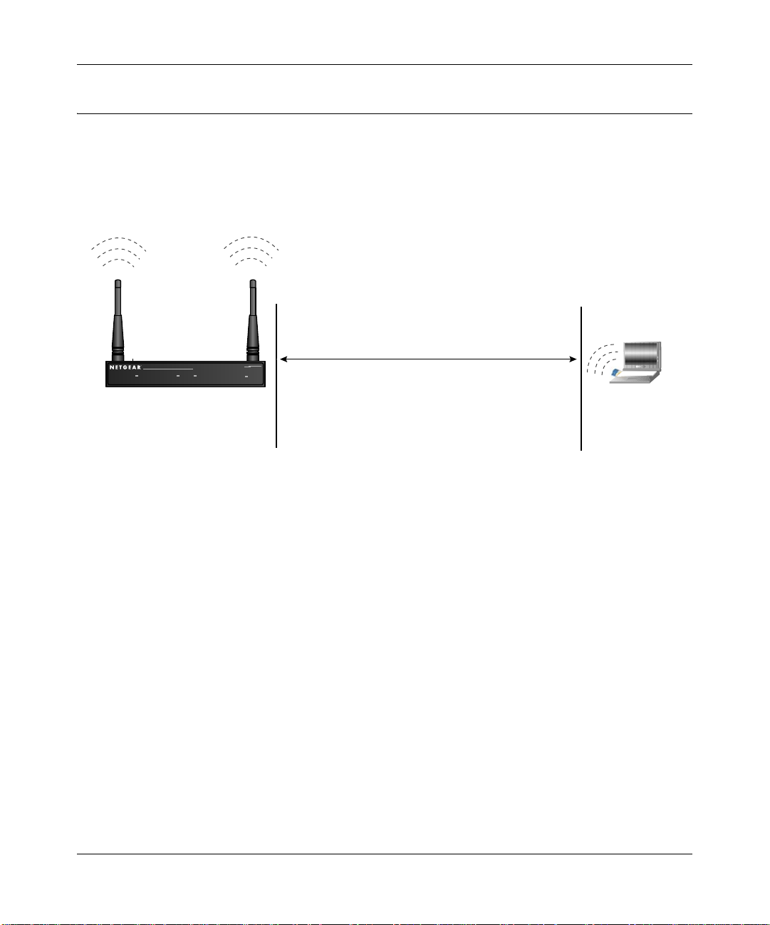
Understanding WG302 Wireless Security Options
Unlike wired network data, your wireless data transmissions can be received well beyond your
walls by anyone with a compatible adapter. For this reason, use the security features of your
wireless equipment. The WG302 Access Point provides highly effective security features which
are covered in detail in this chapter. Deploy the security features appropriate to your needs.
Wireless Data
WG302
Security Options
Range: Up to 500 Foot Radius
802.11b
ProSafeWireless AccessPoint
PWR LAN
WirelessLAN
Figure 3-1: WG302 wireless data security options
There are several ways you can enhance the security of your wireless network:
• Restrict Access Based on MAC address. You can restrict access to only trusted PCs so that
unknown PCs cannot wirelessly connect to the WG302. MAC address filtering adds an
obstacle against unwanted access to your network, but the data broadcast over the wireless link
is fully exposed.
• Turn Off the Broadcast of the Wireless Network Name (SSID). If you disable broadcast of
the SSID, only devices that have the correct SSID can connect. This nullifies the wireless
network ‘discovery’ feature of some products such as Windows XP, but the data is still fully
exposed to a determined snoop using specialized test equipment like wireless sniffers.
• Use WEP. Wired Equivalent Privacy (WEP) data encryption provides data security. WEP
Shared Key authentication and WEP data encryption will block all but the most determined
eavesdropper.
MODEL
ME103
1) Open System: Easy but no security
2) MAC Access List: No data security
3) WEP: Security but some vulnerabilities
Basic Installation and Configuration 3-4
December 2003
Page 26

Reference Manual for the WG302 802.11g ProSafe Wireless Access Point
Installing the WG302 802.11g ProSafe Wireless Access Point
Before installing the WG302 802.11g ProSafe Wireless Access Point, you should make sure that
your Ethernet network is up and working. You will be connecting the access point to the Ethernet
network so that computers with 802.11b or 802.11g wireless adapters will be able to communicate
with computers on the Ethernet network. In order for this to work correctly, verify that you have
met all of the system requirements, shown on page 2-4.
1SET UP THE WG302 ACCESS POINT
Tip: Before mounting the WG302 in a high location, first set up and test the WG302 to verify
wireless network connectivity.
a. Prepare a PC with an Ethernet adapter. If this PC is already part of your network, record its
TCP/IP configuration settings.
b. Configure the PC with a static IP address of 192.168.0.210 and 255.255.255.0 for the
Subnet Mask.
c. Connect an Ethernet cable from the WG302 to the PC (A).
d. Turn on your computer, connect the power adapter to the WG302 and verify the following:
– The PWR power light goes on.
– The LAN light of the wireless access point is lit when connected to a powered on PC.
2CONFIGURE LAN AND WIRELESS ACCESS
a. Configure the WG302 Ethernet port for LAN access.
– Connect to the WG302 by opening your browser and en teri ng http://192.168.0.228 in
the address field.
– When prompted, enter admin for the user name and password for the password, both
in lower case letters.
3-5 Basic Installation and Configuration
December 2003
Page 27

Reference Manual for the WG302 802.11g ProSafe Wireless Access Point
Figure 3-2: Login result: WG302 home page
The Web browser will then display the WG302 home page.
– Click the IP Settings link and configure the IP Settings for your network.
b. Configure the wireless interface for wireless access. See the online help or the
Understanding Basic Wireless Settings topic of this Reference Manual for full
instructions.
Note: You must set the Regulatory Domain. It may not be legal to operate the wireless
access point in a region other than one of those identified in this field.
Now that you have finished the setup steps, you are ready to deploy the WG302 in your
network. If needed, you can now reconfigure the PC you used in step 1 back to its original
TCP/IP settings.
Basic Installation and Configuration 3-6
December 2003
Page 28

Reference Manual for the WG302 802.11g ProSafe Wireless Access Point
3DEPLOY THE WG302 ACCESS POINT
a. Disconnect the WG302 and position it where you will deploy it. The best location is
elevated, such as wall mounted or on the top of a cubicle, at the center of your wireless
coverage area, and within line of sight of all the mobile devices.
b. Lift the antenna on either side so that they are vertical.
Note: Consult the antenna positioning and wireless mode configuration information in the
Advanced Configuration chapter of the Reference Manual.
c. Connect an Ethernet cable from your WG302 Access Point to a LAN port on your router,
switch, or hub.
Note: By default, WG302 is set to with the DHCP client disabled. If your network uses
dynamic IP addresses, you will need to change this setting.
d. Connect the power adapter to the wireless access point and plug the power adapter in to a
power outlet. The PWR, LAN, and Wireless LAN lights and should light up.
e. Connect the power adapter to the wireless access point and plug the power adapter in to a
power outlet. The PWR, LAN, and Wireless LAN lights and should light up.
4VERIFY WIRELESS CONNECTIVITY
Using a computer with an 802.11b or 802.11g wireless adapter with the correct wireless
settings needed to connect to the WG302 (SSID, WEP, MAC ACL, etc.), verify connectivity
by using a browser such as Netscape or Internet Explorer to browse the Internet, or check for
file and printer access on your network.
Note: If you are unable to connect, see Chapter 6, “Troubleshooting.”
Enter the default user name of admin and the default password of password.
3-7 Basic Installation and Configuration
December 2003
Page 29

Reference Manual for the WG302 802.11g ProSafe Wireless Access Point
How to Log In to the WG302 Using Its Default IP Address
1. 192.168.0.228 is the default IP address of your access point. However, the WG302 is also set,
by default, to be a DHCP client. So, if the WG302 has not yet been installed, and there is no
DHCP server on the network, you can log in to the WG302 using its default IP address. You
should use either the NetBIOS name printed on the bottom label to log in.
Note: The computer you are using to connect to the WG302 should be configured with an IP
address that starts with 192.168.0.x and a Subnet Mask of 255.255.255.0.
2. Open a Web browser such as Internet Explorer or Netscape Navigator.
3. Connect to the WG302 by entering its default address of http://192.168.0.228 into your
browser.
4. A login window like the one shown below opens:
Figure 3-3: Login window
Log in use the default user name of admin and default password of password.
Once you have entered your access point name, your Web browser should automatically find
the WG302 Access Point and display the home page, as shown i n “Login result: WG302 home
page” on page 3-6.
Basic Installation and Configuration 3-8
December 2003
Page 30

Reference Manual for the WG302 802.11g ProSafe Wireless Access Point
Understanding Basic Wireless Settings
To configure the wireless settings of your wireless access point, click the Wireless Settings link in
the Basic section of the main menu of the browser interface. The Basic Wireless Settings menu
will appear, as shown below.
Figure 3-4: Basic Wireless Settings menu
The Basic Wireless Settings menu options are discussed below:
• Wireless Network Name (SSID). The SSID is also known as the wireless network name.
Enter a value of up to 32 alphanumeric characters. In a setting where there is more than one
wireless network, different wireless network names provide a means for separating the traffic.
Any device you want to participate in a particular wireless network will need to use the SSID.
The WG302 default SSID is: NETGEAR.
– A group of Wireless Stations and a single access point, all using the same ID (SSID), form
a Basic Service Set (BSS).
– Using the same SSID is essential. Devices with different SSIDs are unable to
communicate with each other. However, some access points allow connections from
wireless stations which have their SSID set to “any” or whose SSID is blank (null).
– A group of wireless stations and multiple access points, all using the same ID (ESSID),
form an Extended Service Set (ESS).
3-9 Basic Installation and Configuration
December 2003
Page 31

Reference Manual for the WG302 802.11g ProSafe Wireless Access Point
– Different access points within an ESS can use different channels. T o reduce interference, it
is recommended that adjacent access points should use different channels.
– As wireless stations physically move through the area covered by an ESS, they will
automatically change to the access point which has the least interference or best
performance. This capability is called roaming.
• Broadcast Wireless Network Name (SSID). This field lets you turn off the SSID broadcast.
If you turn off the SSID broadcast, only stations that know the SSID will connect. Disabling
SSID broadcast somewhat hampers the wireless network ‘discovery’ feature of some products.
The default is to enable SSID broadcast.
• Country/Region. This field identifies the region where the WG302 can be used. It may not be
legal to operate the wireless features of the wireless access point in a region other than one of
those identified in this field. There is no default country domain, and the channel is set to 11.
Unless a country domain is selected, the channel cannot be changed.
• Operating Mode. Select the desired wireless operating mode. The options are:
– Auto (11g and 11b) – Both 802.11g and 802.11b wireless stations can be used. This is the
default
– 11g Only - Only 8 02.1 1g wireless stations can be used. This is required for 10 8 Mbps data
rate operation.
– 11b Only - All 802.1 1b wireless stations can be used. 802.1 1g wireless stations can still be
used if they can operate in 802.11b mode.
• Channel. This field identifies which operating frequency will be used. It should not be
necessary to change the wireless channel unless you notice interference problems or setting up
the WG302 near another access point. See “Wireless Channels” on page B-7 for more
information on wireless channels.
– Access points use a fixed channel. You can select the channel used. This allows you to
choose a channel which provides the least interference and best performance. In the USA
and Canada, 11 channels are available.
Note: Channel 6 is required for 108 Mbps data rate.
– If using multiple access points, it is better if adjacent access points use different channels
to reduce interference. The recommended channel spacing between adjacent access points
is 5 channels (for example, use channels 1 and 6, or 6 and 11).
– In "Infrastructure" mode, wireless stations normally scan all channels, looking for an
access point. If more than one access point can be used, the one with the strongest signal is
used. This can only happen when the various access points are using the same SSID.
Basic Installation and Configuration 3-10
December 2003
Page 32

Reference Manual for the WG302 802.11g ProSafe Wireless Access Point
• Data Rate. Shows the available transmit data rate of the wireless network. 108 Mbps is only
available when the operating mode is 802.11g only and the channel is 6. The default is Best.
• Output Power. Set the transmit signal strength of the access point. The options are full, half,
quarter, eighth, and min. Decrease the transmit power if more than one AP is co-located using
the same channel frequency. The default is Full.
Understanding Basic Wireless Security Options
The table below identifies the various basic wireless security options. A full explanation of these
standards is available in Appendix B, “Wireless Networking Basics”.
Figure 3-5: Wireless Security Settings
3-11 Basic Installation and Configuration
December 2003
Page 33

Reference Manual for the WG302 802.11g ProSafe Wireless Access Point
Table 3-1. Basic Wireless Security Options
Field Description
Network
Authentication
Encryption Strength
Security Encryption
(WEP) Keys
Y ou can select the followin g network authentication options:
• Open System: the WG302 does not perform any au thentication. However, if the
802.1x option is configured, authentication of connections can be performed by a
RADIUS server.
• Shared: this is for shared key authentication. The SSID and data are encrypted.
Y ou can select the followin g data encryption o ptions:
• Disabled
• 64- 128- or 152-bit WEP
With Open System Authentication and 64- 128- or 152-bit WEP Data Encryption,
the WG302 does perform data encryption but does not perform any
authentication.
If WEP is enabled, you can manually or automatically program the four data
encryption keys. These values must be identical on all PCs and access points in
your network (key 1 must be the same for all, key 2 must be the same for all, etc.)
There are two methods for creating WEP encryption keys:
• Passphrase.
These characters are case sensitive.
Enter a word or group of printable characters in the Passphrase box and click the
Generate button.
Note: Not all wireless adapters support passphrase key generation.
• Manual.
These values are not case sensitive.
64-bit WEP: enter 10 hexadecimal digits (any combination of 0-9, a-f, or A-F).
128-bit WEP: enter 26 hexadecimal digits (any combination of 0-9, a-f, or A-F).
152-bit WEP: enter 32 hexadecimal digits (any combination of 0-9, a-f, or A-F).
Enable Wireless
Security
Separator
The associated wireless clients will not be able to communicate with each other if
this feature is enabled. The default setting is Disable.
Basic Installation and Configuration 3-12
December 2003
Page 34

Reference Manual for the WG302 802.11g ProSafe Wireless Access Point
Information to Gather Before Changing Basic Wireless Settings
Before customizing your wireless settings, print this form and record the following information. If
you are working with an existing wireless network, the person who set up or is responsible for the
network will be able to provide this information. Otherwise, you will choose the settings for your
wireless network. Either way, record the settings for your wireless network in the spaces below.
• Wireless Network Name (SSID): ______________________________
The SSID, identifies
the wireless network. You can use up to 32 alphanumeric characters. The SSID is case
sensitive.
Note: The SSID in the wireless adapter card must match the SSID of the wireless access point.
In some configuration utilities (such as in Windows XP), the term “wireless network name” is
used instead of SSID.
• Authentication. Circle one: Open System or Shared Key.
Authentication is unrelated to encryption of data transmissions. Shared Key provides more
network access security.
Note: If you select Shared Key, the other devices in the network will not connect unless they
are set to Shared Key as well and are configured with the correct key.
• WEP Encryption key size. Choose one: 64- 128- or 152-bit. Larger bit sizes provide stronger
data security. Again, the encryption key size must be the same for the wireless adapters and the
wireless access point.
• Data Encryption (WEP) Keys.
There are two methods for creating WEP data encryption keys. Whichever method you use,
record the key values in the spaces below.
– Passphrase method. ______________________________
These characters are case
sensitive. Enter a word or group of printable characters. When you enter the Passphrase
and click the Generate Key button on the WG302, the keys will be generated.
– Manual method. These values are not case sensitive. For 64-bit WEP, enter 10 hex digits
(any combination of 0-9 or a-f). For 128-bit WEP, enter 26 hex digits. For 152-bit WEP,
enter 32 hex digits.
Key 1: ___________________________________
Key 2: ___________________________________
Key 3: ___________________________________
Key 4: ___________________________________
Use the procedures described in the following sections to configure the WG302. Store this
information in a safe place.
3-13 Basic Installation and Configuration
December 2003
Page 35

Reference Manual for the WG302 802.11g ProSafe Wireless Access Point
How to Set Up and Test Basic Wireless Connectivity
Follow the instructions below to set up and test basic wireless connectivity. Once you have
established basic wireless connectivity , you can enable security settings appropriate to your needs.
1. Log in to the WG302 using the NetBIOS name printed on the bottom of the unit or at its
default address of http://192.168.0.228 or at whatever IP address the unit is currently
configured. Use the default user name of admin and default password of password, or
whatever password you set up.
2. Click the Wireless Settings link in the main menu of the WG302.
3. Choose a suitable descriptive name for the wireless network name (SSID). In the SSID box,
enter a value of up to 32 alphanumeric characters. The default SSID is NETGEAR.
Note: The SSID of any wireless access adapters must match the SSID you configure in the
WG302 802.11g ProSafe Wireless Access Point. If they do not match, you will not get a
wireless connection to the WG302.
4. Select the Country/Region in which the wireless interface will operate.
5. Set the Channel. It should not be necessary to change the wireless channel unless you notice
interference problems or are near another wireless access point. Select a channel that is not
being used by any other wireless networks within several hundred feet of your wireless access
point. For more information on the wireless channel frequencies see “Wireless Channels” on
page B-7.
6. For initial configuration and testing, leave the Wireless Card Access List set to “Everyone”
and the Encryption Strength set to “Disabled.”
7. Click Apply to save your changes.
Note: If you are configuring the WG302 from a wireless PC and you change the SSID,
channel, or security settings, you will lose your wireless connection when you click
Apply . You must then change the wireless settings of your PC to match the new settings.
8. Configure and test your PCs for wireless connectivity.
Program the wireless adapter of your PCs to have the same SSID and channel that you
configured in the WG302. Check that they have a wireless link and are able to obtain an IP
address by DHCP from the WG302.
Once your PCs have basic wireless connectivity to the WG302, you can configure the advanced
wireless security functions.
Basic Installation and Configuration 3-14
December 2003
Page 36

Reference Manual for the WG302 802.11g ProSafe Wireless Access Point
How to Restrict Wireless Access by MAC Address
To restrict access based on MAC addresses, follow these steps:
1. Log in to the WG302 using the NetBIOS name printed on the bottom of the unit or at its
default address of http://192.168.0.228 or at whatever IP address the unit is currently
configured. Use the default user name of admin and default password of password, or
whatever LAN address and password you have set up.
Note: When configuring the WG302 from a wireless PC whose MAC address is not in
the access control list, if you select Turn Access Control On, you will lose your wireless
connection when you click Apply . You must then access the wireless access point from a
wired PC or from a wireless PC which is on the access control list to make any further
changes.
2. From the Wireless Settings menu, click the W ireless Station List button to display the W ireless
Access menu shown below.
Figure 3-6: Access Control List menu
3-15 Basic Installation and Configuration
December 2003
Page 37

Reference Manual for the WG302 802.11g ProSafe Wireless Access Point
Select the Turn Access Control On check box.
3.
4. Then, either select from the list of available w ireless ca rds the WG30 2 has foun d in your area,
or enter the MAC address and device name for a device you plan to use. You can usually find
the MAC address printed on the wireless adapter.
5. Click Add to add the wireless device to the access list. Repeat these steps for each additional
device you want to add to the list.
6. Be sure to click Apply to save your wireless access control list settings.
Now, only devices on this list will be allowed to wirelessly connect to the WG302.
How to Configure WEP
To configure WEP data encryption, follow these steps:
1. Log in to the WG302 using the NetBIOS name printed on the bottom of the unit or at its
default address of http://192.168.0.228 or at whatever IP address the unit is currently
configured Use the default user name of admin and default password of password, or
whatever LAN address and password you have set up.
2. Click the Wireless Settings link in the Advanced section of the main menu of the WG302.
3. Choose Open System or Shared Key authentication.
4. Select encryption strength.
5. You can manually or automatically program the four data encryption keys. These values must
be identical on all PCs and Access Points in your network.
• Automatic - enter a word or group of printable characters in the Passphrase box and click
the Generate button. The four key boxes will be automatically populated with key values.
• Manual - enter ten hexadecimal digits (any combination of 0-9, a-f, or A-F)
Select which of the four keys will be the default.
See “Overview of WEP Parameters” on page B-5 for a full explanation of each of these
options, as defined by the IEEE 802.11 wireless communication standard.
6. Click Apply to save your settings.
Note: If you use a wireless PC to configure WEP settings, you will be disconnected
when you click Apply. Reconfigure your wireless adapter to match the new settings or
access the wireless access point from a wired PC to make any further changes.
Basic Installation and Configuration 3-16
December 2003
Page 38

Reference Manual for the WG302 802.11g ProSafe Wireless Access Point
Using the Basic IP Settings Options
The Basic IP Settings menu is under the Basic heading of the main menu. Use this menu to
configure DHCP, static IP, and access point NetBIOS name settings.
Figure 3-7: IP Settings menu
• Access Point Name (NetBIOS)
Enter a new name for the wireless access point and click Apply to save your changes.
• The IP Address
The wireless access point is shipped preconfigured to use a private IP address on the LAN
side, and to act as a DHCP client. If the wireless access point does not find a DHCP server on
the Ethernet LAN, it defaults to this IP configuration:
– IP Address— 192.168.0.228
– IP Subnet Mask— 255.255.255.0
– Gateway — 0.0.0.0
If your network has a requirement to use a different IP addressing scheme, you can make those
changes in this menu. These settings are only required if the “Use this IP address” radio button
is chosen. Remember to click Apply to save your changes.
3-17 Basic Installation and Configuration
December 2003
Page 39

Chapter 4
Management
This chapter describes how to use the management features of your WG302 802.11g ProSafe
Wireless Access Point. These features can be found by clicking on the Maintenance heading in the
Main Menu of the browser interface.
Using the Secure Telnet Interface
The WG302 includes a secure Telnet command line interface (CLI). You can access the CLI from
a secure Telnet client over the Ethernet port or over the serial console port.
.
Note: You must use a secure Telnet client such as Absolute Telnet. Also, when you
configure the client, use the SSH1, 3DES option. If you use the Telnet client to connect
over the Ethernet port, use the IP address of the WG302 as the host name.
How to Use the CLI via the Console Port:
1. Using the null-modem cable, connect a VT100/ANSI terminal or a workstation to the
port labeled Console.
If you attached a PC, Apple Macintosh, or UNIX workstation, start a secure
terminal-emulation program.
2. Configure the terminal-emulation program to use the following settings:
• Baud rate: 9,600 bps
• Data bits: 8
• Parity: none
• Stop bit: 1
• Flow control: none
These settings appear below the connector on the back panel.
Management 4-1
December 2003
Page 40

Reference Manual for the WG302 802.11g ProSafe Wireless Access Point
Press the return key, and the screen below should appear.
3.
Figure 4-1: Secure Telnet Client
The login name is admin and password is the default password.
After successful login, the screen should show the (NetBIOS Name)> prompt In this example
the prompt is (netgear74F35E) >.
Enter help to display the CLI command help..
CLI Commands
The CLI commands are listed in the following table.
Table 4-1. CLI Commands
Command Function
get association Display Associated station list
get authentication Display Authentication Type
get BeaconInterval Display Beacon period in TU(1024 us)
get channel Display Refer to the result of "get channels"
get channels Display Valid channels for current Country/Region
get CountryCode Display Country and Region
get DTIM Display DTIM Period in Beacon Interval
get encryption Display Data Encryption
get FragmentationThreshold Display Fragmentation Threshold (even only)
get key Display Key table maintenance
get KeyDefault Display Default WEP Key ID
4-2 Management
December 2003
Page 41

Reference Manual for the WG302 802.11g ProSafe Wireless Access Point
Table 4-1. CLI Commands
Command Function
get power Display Transmit Power
get preamble Display Only effect on 802.11b rates
get rate Display Transmit rate
get RTSThreshold Display RTS/CTS Threshold
get SSID Display Network name, 1
get SSIDsuppress Display Suppress SSID broadcast
get WirelessIsolate Display Isolate communication between wireless clients
get WirelessMode Display Wireless Mode
get WlanMac Display Wlan MAC Address
get WlanState Display WLAN statistic
get WlanVersion Display Wireless driver version
get IPAddress Display IP address setting
set authentication Set Authentication Type
set BeaconInterval Set Beacon period in TU(1024 us)
set channel Set Refer to the result of "get channels"
set CountryCode Set Country and Region
set DTIM Set DTIM Period in Beacon Interval
set encryption Set Data Encryption
set FragmentationThreshold Set Fragmentation Threshold (even only)
set key Set Key table maintenance
set KeyDefault Set Default WEP Key ID
set power Set Transmit Power
set preamble Set Only effect on 802.11b rates
set rate Set Transmit rate
set RTSThreshold Set RTS/CTS Threshold
set SSID Set Network name, 1
set SSIDsuppress Set Suppress SSID broadcast
set WirelessIsolate Set Isolate communica tion between wireless clients
set WirelessMode Set Wireless Mode
del key Delete Key table maintenance
Management 4-3
December 2003
Page 42

Reference Manual for the WG302 802.11g ProSafe Wireless Access Point
Table 4-1. CLI Commands
Command Function
version display FW version
quit exit the cli
exit logout
help display help message
reboot reboot the device
4-4 Management
December 2003
Page 43

Reference Manual for the WG302 802.11g ProSafe Wireless Access Point
Viewing General, Log, Station, and Statistical Information
The General information screen provides a summary of the current WG302 configuration settings.
From the main Menu of the browser interface, click General to view the System Status screen,
Management 4-5
December 2003
Page 44

Reference Manual for the WG302 802.11g ProSafe Wireless Access Point
shown below.
Figure 4-2: Wireless Access Point Status screen
This screen shows the following parameters:
Table 4-1. General Information Fields
Field Description
Access Point Information
Access Point Name The default name may be changed if desired.
MAC Address Displays the Media Access Control address (MAC address) of the wireless
access point’s Ethernet port.
Country/Region
Firmware Version The version of the firmware currently inst alled.
Current IP Settings
4-6 Management
Displays the domain or region for which the wireless access point is
licensed for use. It may not be legal to operate this wireless access point in
a region other than one of those identified in this field.
December 2003
Page 45

Reference Manual for the WG302 802.11g ProSafe Wireless Access Point
Table 4-1. General Information Fields
Field Description
IP Address The IP address of the wireless access point.
Subnet Mask
The subnet mask for the wireless access point.
Gateway
DHCP Client Enabled indicates that the current IP address was obtained from a DHCP
Current Wireless Settings
Access Point Mode
Operating Mode
Wireless Network Name
(SSID)
Channel Identifies the channel the wireless port is using. 11 is the default channel
Operating Mode
WEP WEP setting.
The default gateway for the wireless access point communication.
server on your network. Disabled indicated a static IP configuration.
Identifies the operating mode of the WG302: Access Point, Point-to-point
bridge, Multi-point bridge or Repeater.
Identifies the operating mode of the WG302.
Displays the wireless network name (SSID) being used by the wireless port
of the wireless access point. The default is NETGEAR.
setting. See “Wireless Channels” on page B-7 for the frequencies used on
each channel.
Identifies the operating mode of the WG302.
Statistics
The Information - Statistics screen provides various LAN and WLAN statistics.
Management 4-7
December 2003
Page 46

Reference Manual for the WG302 802.11g ProSafe Wireless Access Point
Figure 4-3: Wireless Access Point Status screen
Table 4-1. Statistics Fields
Field Description
Wired Ethernet Re ce iv ed/ Transmitted
Packets The number of packets sent since the WG302 was last restarted.
Bytes
Wireless
Unicast Packets The Unicast packets sent since the WG302 was last restarted.
Broadcast Packets The Broadcast packets sen t since the WG302 was last restarted.
Multicast Packets The Multicast packets sent since the WG302 was last restarted.
Total Packets The Wireless packets sent since the WG302 was last restarted.
Total Bytes The Wireless bytes sent since the WG302 was last restarted.
Refresh button
The number of bytes sent since the WG302 was last restarted.
Received/Transmitted
Click the Refresh button to update the statistics on this screen.
4-8 Management
December 2003
Page 47

Reference Manual for the WG302 802.11g ProSafe Wireless Access Point
Viewing a List of Attached Devices
The Station List menu contains a table of all IP devices associated with the wireless access point in
the wireless network defined by the Wireless Network Name (SSID). From the main menu of the
browser interface, under the Information heading, click the Station List link to view the list, shown
below.
Figure 4-4: Information Station List of associated devices
For each device, the table shows the MAC address and whether the device is allowed to
communicate with the wireless access point or not. Note that if the wireless access point is
rebooted, the table data is lost until the wireless access point rediscovers the devices. To force the
wireless access point to look for associated devices, click the Refresh button.
Note: A wireless network can include multiple wireless access points, all using the same network
name (SSID). This enables extending the reach of the wireless network and allows users to roam
from one access point to another, providing seamless network connectivity. Under these
circumstances, be aware that only the stations associated with this access point will be presented in
the Station List.
Management 4-9
December 2003
Page 48

Reference Manual for the WG302 802.11g ProSafe Wireless Access Point
Upgrading the Wireless Access Point Software
.
Note: When uploading software to the WG302 Access Point, it is important not to
interrupt the W eb browser by closing the wind ow , clicking a link, or loading a new page.
If the browser is interrupted, the upload may fail, corrupt the software, and render the
WG302 completely inoperable.
You cannot perform the firmware upgrade from a workstation connected to the WG302 via a
wireless link. The firmware upgrade must be performed via a workstation connected to the
WG302 via the Ethernet LAN interface.
The software of the WG302 Access Point is stored in FLASH memory, and can be upgraded as
new software is released by NETGEAR. Upgrade files can be downloaded from Netgear's Web
site. If the upgrade file is compressed (.ZIP file), you must first extract the image (.RMG) file
before sending it to the wireless access point. The upgrade file can be sent using your browser.
Note: The Web browser used to upload new firmware into the WG302 must support HTTP
uploads, such as Microsoft Internet Explorer 6.0 or above, or Netscape Navigator 4.78 or above.
1. Download the new software file from NETGEAR, save it to your hard disk, and unzip it.
2. From the main menu Management section, click the Upgrade Firmware link to display the
screen above.
3. In the Upgrade Firmware menu, click the Browse button and browse to the location of the
image (.RMG) upgrade file.
4. Click Upload.
When the upload completes, your wireless access point will automatically restart. The upgrade
process typically takes about one minute.
In some cases, you may need to reconfigure the wireless access point after upgrading.
4-10 Management
December 2003
Page 49

Reference Manual for the WG302 802.11g ProSafe Wireless Access Point
Configuration File Management
The WG302 Access Point settings are stored in the wireless access point in a configuration file.
This file can be saved (backed up) to a user’s PC, retrieved (restored) from the user’s PC, or
cleared to factory default settings.
From the main menu Management heading, click the Backup/Restore Settings link to bring up the
menu shown below.
Figure 4-5: Settings Backup menu
The three options displayed are described in the following sections:
Saving and Retrieving the Configuration
The Backup/Restore Settings menu allows you to save or retrieve a file containing your wireless
access point’s configuration settings.
Management 4-11
December 2003
Page 50

Reference Manual for the WG302 802.11g ProSafe Wireless Access Point
To save your settings, click the Save button. Your browser will extract the configuration file from
the wireless access point and prompts you for a location on your PC to store the file. You can give
the file a meaningful name at this time, such as WG302.cfg.
T o restore your settings from a saved configuration file, enter the full path to the fil e on your PC or
click the Browse button to locate the file. When you have located it, click the Retrieve button to
upload the file. After completing the upload, the WG302 will reboot automatically.
Restoring the WG302 to the Factory Default Settings
It is sometimes desirable to restore the wireless access point to the factory default settings. This
can be done by using the Restore function, which restores all factory settings. After a restore, the
wireless access point's password will be password, the WG302's DHCP client is enabled, the
default LAN IP address is 192.168.0.228, and the access point name is reset to the name printed on
the label on the bottom of the unit.
Using the Reset Button to Restore Factory Default Settings
To restore the factory default configuration settings without knowing the login password or IP
address, you must use the Default Reset button on the rear panel of the wireless access point (see
“WG302 Wireless Access Point Rear Panel” on page 2-7). The reset button has two functions:
• Reboot. When pressed and released, the Wireless Access Point will reboot (restart).
• Reset to Factory Defaults. This button can also be used to clear all data and restore all
settings to the factory default values.
To clear all data and restore the factory default values:
1. Power Off the WG302
2. Hold the Reset Button down while you Power On the WG302 for 5 seconds.
3. Continue holding the Reset Button until the LEDs blink twice.
4. Release the Reset Button.
The factory default configuration has now been restored, and the WG302 is ready for use.
4-12 Management
December 2003
Page 51

Reference Manual for the WG302 802.11g ProSafe Wireless Access Point
Changing the Administrator Password
The default password is password. Change this password to a more secure password. You cannot
change the administrator login name.
From the main menu of the browser interface, under the Management heading, click Change
Password to bring up the menu shown below.
Figure 4-6: Set Password menu
T o change the password, first enter the old password, and then enter the new password twice. Click
Apply to save your change.
Management 4-13
December 2003
Page 52

Reference Manual for the WG302 802.11g ProSafe Wireless Access Point
4-14 Management
December 2003
Page 53

Chapter 5
Advanced Configuration
This chapter describes how to configure the advanced features of your WG302 802.11g ProSafe
Wireless Access Point. These features can be found under the Advanced heading in the main
menu.
Understanding Advanced Wireless Settings
The default advanced wireless settings usually work well. These settings should not be changed
unless you are sure it is necessary.
Figure 5-1: Advanced Wireless Settings screen
Table 5-1. Advanced Wireless LAN Settings Fields
Field Description
RTS Threshold The packet size used to determine whether it should use the CSMA/CD (Carrier
Sense Multiple Access with Collision Detection) or the CSMA/CA (Carrier Sense
Multiple Access with Collision Avoidance) mechanism for packet transmission.
Fragmentation
Length
Beacon Interval Specifies the data beacon rate between 20 and 3000.
Preamble Type A long transmit preamble may provide a more reliable connection or slightly longer
Advanced Configuration 5-1
This is the maximum packet size used for fragmentation. Packets larger than the
size programmed in this field will be fragmented. The Fragment Threshold value
must be larger than the RTS Threshold value.
range. A short transmit preamble gives better performance. Long is the default.
December 2003
Page 54

Reference Manual for the WG302 802.11g ProSafe Wireless Access Point
Configuring Wireless Operating Modes
The WG302 802.11g ProSafe Wi reless Access Point lets you build large bridged wireless
networks.
Figure 5-2: Advanced Wireless Settings Access Point Mode settin gs
Examples of wireless bridged configurations are:
• Client Access Point to Access Point, the default
• Point-to-Point Bridge
• Multi-Point Bridge
• Repeater with Wireless Client Association
These features are discussed below.
5-2 Advanced Configuration
December 2003
Page 55

Reference Manual for the WG302 802.11g ProSafe Wireless Access Point
LAN
Segment 1
Router
AP in
Point-to-Point
Bridge Mode
AP in
Point-to-Point
Bridge Mode
LAN
Segment 2
Hub or Switch
AP1
ETHERNET
RESET
5-12VDC
AP2
ETHERNET
RESET
5-12VDC
How to Configure a WG302 as a Point-to-Point Bridge
Figure 5-3: Point-to-Point Bridge
Configure the WG302 (AP1) on LAN Segment 1 in Point-to-Point Bridge mode.
1.
2. Configure the WG302 (AP2) on LAN Segment 2 in Point-to-Point Bridge mode.
AP1 must have AP2’s MAC address in its Remote MAC Address field and AP2 must have
AP1’s MAC address in its Remote MAC Address field.
3. Configure and verify the following parameters for both access points:
• Verify that the LAN network configuration of the WG302 Access Points both are
configured to operate in the same LAN network address range as the LAN devices
• Both use the same ESSID, Channel, authentication mode, if any, and security settings if
security is in use.
4. Verify connectivity across the LAN 1 and LAN 2.
• A PC on either LAN segment should be able to connect to the Internet or share files and
printers of any other PCs or servers connected to LAN Segment 1 or LAN Segment 2.
Advanced Configuration 5-3
December 2003
Page 56

Reference Manual for the WG302 802.11g ProSafe Wireless Access Point
How to Configure Multi-Point Wireless Bridging
AP3
ETHERNET
RESET
Hub or Switch
LAN
Segment 3
5-12VDC
Router
192.168.0.1
LAN
AP in
Point-to-Point
Bridge Mode
AP1
RESET
ETHERNET
5-12VDC
AP2
RESET
'Master' AP in
Point-to-Multi-Point
Bridge Mode
Hub or Switch
AP in
Point-to-Point
Bridge Mode
ETHERNET
5-12VDC
Segment 1
LAN
Segment 2
Figure 5-4: Multi-Point bridging
Configure the Operating Mode of the WG302 Access Points.
1.
– WG302 (AP1) on LAN Segment 1 in Point-to-Point Bridge mode with the Remote MAC
Address of AP2.
– Because it is in the central location, configure WG302 (AP2) on LAN Segment 2 in
Point-to-Multi-Point Bridge mode. No MAC address is required because it will respond to
Point-to-Point APs which are configured communicating to it.
– Configure the WG302 (AP3) on LAN 3 in Point-to-Point Bridge mode with the Remote
MAC Address of AP2.
2. Verify the following parameters for all access points:
• Verify that the LAN network configuration the WG302 Access Points are configured to
operate in the same LAN network address range as the LAN devices
• Only one AP is configured in Point-to-Multi-Point Bridge mode, and all the others are in
Point-to-Point Bridge mode.
• All APs must be on the same LAN. That is, all the APs LAN IP address must be in the
same network.
• If using DHCP, all WG302 Access Points should be set to “Obtain an IP address
automatically (DHCP Client)” in the IP Address Source portion of the Basic IP Settings
menu.
5-4 Advanced Configuration
December 2003
Page 57

Reference Manual for the WG302 802.11g ProSafe Wireless Access Point
• All WG302 Access Points use the same SSID, Channel, authentication mode, if any, and
encryption in use.
• All Point-to-Point APs must have AP2’s MAC address in its Remote AP MAC address
field.
3. Verify connectivity across the LANs.
• A PC on any LAN segment should be able to connect to the Internet or share files and
printers with any other PCs or servers connected to any of the three LAN segments.
• Wireless stations will not be able to connect to the WG302 Access Points in the
illustration above. If you require wireless stations to access any lan segment, you can
additional WG302 Access Points configured in Wireless Access Point mode to any LAN
segment.
Note: You can extend this multi-point bridging by adding additional WG302s configured in
Point-to-Point mode for each additional LAN segment. Furthermore, you can extend the range of
the wireless network with NETGEAR wireless antenna accessories.
How to Configure Wireless Repeating
AP3
ETHERNET
5-12VDC
RESET
AP in Repeater Mode
with client associations
Wireless PC
Associated with AP1
AP1
ETHERNET
5-12VDC
RESET
AP in Repeater Mode
with client associations
AP2
ETHERNET
5-12VDC
Router
192.168.0.1
RESET
AP in Repeater Mode
with client associations
Wireless PC
Associated with AP3
LAN
Segment 1
Wireless PC
Associated with AP2
Figure 5-5: Multi-Point bridging
Configure the Operating Mode of the WG302 Access Points.
1.
– WG302 (AP1) on LAN Segment 1 in Repeater mode with the Remote MAC Address of
AP2.
– Configure WG302 (AP2) in Repeater mode with MAC addresses of AP1 and AP3.
Advanced Configuration 5-5
December 2003
Page 58

Reference Manual for the WG302 802.11g ProSafe Wireless Access Point
– Configure the WG302 (AP3) in Repeater mode with the Remote MAC Address of AP2.
2. Verify the following parameters for all access points:
• Verify that the LAN network configuration the WG302 Access Points are configured to
operate in the same LAN network address range as the LAN devices
• All APs must be on the same LAN. That is, all the APs LAN IP address must be in the
same network.
• If using DHCP, all WG302 Access Points should be set to “Obtain an IP address
automatically (DHCP Client)” in the IP Address Source portion of the Basic IP Settings
menu.
• All WG302 Access Points use the same SSID, Channel, authentication mode, if any, and
encryption in use.
3. Verify connectivity across the LANs.
• A PC on any LAN segment should be able to connect to the Internet or share files and
printers with any other PCs or servers connected to any of the three WLAN segments.
Note: You can extend this repeating by adding up to 2 additional WG302s configured in repeater
mode. However, since Repeater configurations communicate in half-duplex mode, the bandwidth
decreases as you add Repeaters to the network. Also, you can extend the range of the wireless
network with NETGEAR wireless antenna accessories.
5-6 Advanced Configuration
December 2003
Page 59

Chapter 6
Troubleshooting
This chapter provides information about troubleshooting your WG302 802.11g ProSafe Wireless
Access Point. After each problem description, instructions are given to help you diagnose and
solve the problem. For the common problems listed, go to the section indicated.
• Is the WG302 on?
• Have I connected the wireless access point correctly?
Go to “Installing the WG302 802.11g ProSafe Wireless Access Point” on page 3-5.
• I cannot remember the wireless access point’s configuration password.
Go to “Changing the Administrator Password” on page 4-13.
Note: For up-to-date WG302 installation details and troubleshooting guidance visit
www.NETGEAR.com.
If you have trouble setting up your WG302, check the tips below.
No lights are lit on the access point.
It takes a few seconds for the power indicator to light up. Wait a minute and check the
power light status on the access point.
If the access point has no power.
• Make sure the power cord is connected to the access point.
• Make sure the power adapter is connected to a functioning power outlet. If it is in a power
strip, make sure the power strip is turned on. If it is plugged directly into the wall, verify that it
is not a switched outlet.
• Make sure you are using the correct NETGEAR power adapter supplied with your access
point.
Troubleshooting 6-1
December 2003
Page 60

Reference Manual for the WG302 802.11g ProSafe Wireless Access Point
The Wireless LAN activity light does not light up.
The access point’s antennae are not working.
• If the Wireless LAN activity light stays off, disconnect the adapter from its power source and
then plug it in again.
• Make sure the antennas are tightly connected to the WG302.
• Contact NETGEAR if the Wireless LAN activity light remains off.
The LAN light is not lit.
There is a hardware connection problem.Check these items:
• Make sure the cable connectors are securely plugged in at the access point and the network
device (hub, switch, or router). A switch, hub, or router must be installed between the access
point and the Ethernet LAN or broadband modem.
• Make sure the connected device is turned on.
• Be sure the correct cable is used. Use a standard Category 5 Ethernet patch cable. If the
network device has Auto Uplink™ (MDI/MDIX) ports, you can use either a cross-over cable
or a normal patch cable.
I cannot access the Internet or the LAN with a wireless capable computer.
There is a configuration problem.Check these items:
• You may not have restarted the computer with the wireless adapter to have TCP/IP changes
take effect. Restart the computer.
• The computer with the wireless adapter may not have the correct TCP/IP settings to
communicate with the network. Restart the computer and check that TCP/IP is set up properly
for that network. The usual setting for Windows the Network Properties is set to “Obtain an IP
address automatically.”
• The access point’s default values may not work with your network. Check the access point
default configuration against the configuration of other devices in your network.
6-2 Troubleshooting
December 2003
Page 61

Reference Manual for the WG302 802.11g ProSafe Wireless Access Point
I cannot connect to the WG302 to configure it.
Check these items:
• The WG302 is properly installed, LAN connections are OK, and it is powered on. Check that
the LAN port LED is green to verify that the Ethernet connection is OK.
• The default configureation of the WG302 is for a static IP address of 192.168.0.228 and a
Mask of 255.255.255.0 with DHCP disabled. Make sure your network co nfiguration settings
are correct.
• If you are using the NetBIOS name of the WG302 to connect, ensure that your PC and the
WG302 are on the same network segment or that there is a WINS server on your network.
• If your PC is set to “Obtain an IP Address automatically” (DHCP client), restart it.
• If your PC uses a Fixed (Static) IP address, ensure that it is using an IP Address in the range of
the WG302. The WG302 default IP Address is 192.168.0.228 and the default Subnet Mask is
255.255.255.0. If you are not sure about these settings, follow the instructions for “Installing
the WG302 802.11g ProSafe Wireless Access Point” on page 3-5.
When I enter a URL or IP address I get a timeout error.
A number of things could be causing this. Try the following troubleshooting steps.
• Check whether other PCs work. If they do, ensure that your PCs TCP/IP settings are correct. If
using a Fixed (Static) IP Address, check the Subnet Mask, Default Gateway, DNS, and IP
Addresses.
• If the PCs are configured correctly, but still not working, ensure that the WG302 is connected
and turned on. Connect to it and check its settings. If you cannot connect to it, check the LAN
and power connections.
• If the WG302 is configured correctly, check your Internet connection (DSL/Cable modem
etc.) to make sure that it is working correctly.
Using the Reset Button to Restore Factory Default Settings
The Reset button (see “WG302 Wireless Access Point Rear Panel” on page 2-7) has two functions:
• Reboot. When pressed and released quickly, the WG302 will reboot (restart).
Troubleshooting 6-3
December 2003
Page 62

Reference Manual for the WG302 802.11g ProSafe Wireless Access Point
• Reset to Factory Defaults. This button can also be used to clear ALL data and restore ALL
settings to the factory default values.
To clear all data and restore the factory default values:
1. Power off the WG302 and power it back on.
2. Use something with a small point, such as a pen, to press the Reset button in and hold it in for
at least 5 seconds.
3. Release the Reset button.
The factory default configuration has now been restored, and the WG302 is ready for use.
6-4 Troubleshooting
December 2003
Page 63

Reference Manual for the WG302 802.11g ProSafe Wireless Access Point
Appendix A
Specifications
This appendix provides technical specifications for the WG302 802.11g ProSafe Wireless Access
Point.
Specifications for the WG302
Parameter WG302 802.11g ProSafe Wireless Access Point
802.11g Data Rates 1, 2, 5.5, 1 1, 12, 18, 24, 36, 38, 54, & 108 Mbps (Auto-rate capable)
802.11g
Operating Frequencies
802.11g Encryption 40-bits (also called 64-bits), 128- and 152-bits WEP data encryption
Network Management Web-based configuration and status monitoring
Maximum Clients Limited by the amount of wireless network traffic generated by each node;
Status LEDs Power/Ethernet LAN/Wireless LAN/Test
Power Adapter 12Vdc, 1.2 A
Electromagnetic
Compliance
Environmental
Specifications
2.412 ~ 2.462 GHz (US) 2.457 ~ 2.462 GHz (Spain)
2.412 ~ 2.484 GHz (Japan) 2.457 ~ 2.472 GHz (France)
2.412 ~ 2.472 GHz (Europe ETSI)
typically 15 to 20 nodes.
FCC Part 15 Class B and Class E,
Operating temperature: 0 to 50° C
Operating humidity: 5-95%, non-condensing
Specifications A-1
December 2003
Page 64

Reference Manual for the WG302 802.11g ProSafe Wireless Access Point
A-2 Specifications
December 2003
Page 65

Appendix B
Wireless Networking Basics
This chapter provides an overview of wireless networking and security.
Wireless Networking Overview
The WG302 Access Point conforms to the Institute of Electrical and Electronics Engineers (IEEE)
802.11g standard for wireless LANs (WLANs). On an 802.1 1g wireless link, data i s encoded using
direct-sequence spread-spectrum (DSSS) technology and is transmitted in the unlicensed radio
spectrum at 2.5GHz. The maximum data rate for the wireless link is 11 Mbps, but it will
automatically back down from 11 Mbps to 5.5, 2, and 1 Mbps when the radio signal is weak or
when interference is detected.
The 802.11 standard is also called Wireless Ethernet or Wi-Fi by the Wireless Ethernet
Compatibility Alliance (WECA, see http://www.wi-fi.net), an industry standard group promoting
interoperability among 802.11 devices. The 802.11 standard offers two methods for configuring a
wireless network - ad hoc and infrastructure.
Infrastructure Mode
With a wireless Access Point, you can operate the wireless LAN in the infrastructure mode. This
mode provides wireless connectivity to multiple wireless network devices within a fixed range or
area of coverage, interacting with wireless nodes via an antenna.
In the infrastructure mode, the wireless access point converts airwave data into wired Ethernet
data, acting as a bridge between the wired LAN and wireless clients. Connecting multiple Access
Points via a wired Ethernet backbone can further extend the wireless network coverage. As a
mobile computing device moves out of the range of one access point, it moves into the range of
another. As a result, wireless clients can freely roam from one Access Point domain to another and
still maintain seamless network connection.
Wireless Networking Basics B-1
December 2003
Page 66

Reference Manual for the WG302 802.11g ProSafe Wireless Access Point
Ad Hoc Mode (Peer-to-Peer Workgroup)
In an ad hoc network, computers are brought together as needed; thus, there is no structure or fixed
points to the network - each node can generally communicate with any other node. There is no
Access Point involved in this configuration. This mode enables you to quickly set up a small
wireless workgroup and allows workgroup members to exchange data or share printers as
supported by Microsoft networking in the various W indows operating systems. Some vendors also
refer to ad hoc networking as peer-to-peer group networking.
In this configuration, network packets are directly sent and received by the intended transmitting
and receiving stations. As long as the stations are within range of one another, this is the easiest
and least expensive way to set up a wireless network.
Network Name: Extended Service Set Identification (ESSID)
The Extended Service Set Identification (ESSID) is one of two types of Service Set Identification
(SSID). In an ad hoc wireless network with no access points, the Basic Service Set Identification
(BSSID) is used. In an infrastructure wireless network that includes an access point, the ESSID is
used, but may still be referred to as SSID.
An SSID is a thirty-two character (maximum) alphanumeric key identifying the name of the
wireless local area network. Some vendors refer to the SSID as network name. For the wireless
devices in a network to communicate with each other, all devices must be configured with the
same SSID.
Authentication, WEP, and WPA
The absence of a physical connection between nodes makes the wireless links vulnerable to
eavesdropping and information theft. To provide a certain level of security, the IEEE 802.11
standard has defined two types of authentication methods, Open System and Shared Key. With
Open System authentication, a wireless PC can join any network and receive any messages that are
not encrypted. With Shared Key authentication, only those PCs that possess the correct
authentication key can join the network. By default, IEEE 802.11 wireless devices operate in an
Open System network. Recently, Wi-Fi, the Wireless Ethernet Compatibility Alliance
(http://www.wi-fi.net) developed the Wi-Fi Protected Access (WPA), a new strongly enhanced
Wi-Fi security. WPA will soon be incorporated into the IEEE 802.11 standard.
B-2 Wireless Networking Basics
December 2003
Page 67

Reference Manual for the WG302 802.11g ProSafe Wireless Access Point
802.11 Authentication
The 802.11 standard defines several services that govern how two 802.11 devices communicate.
The following events must occur before an 802.11 Station can communicate with an Ethernet
network through an access point such as the one built in to the WG302:
1. Turn on the wireless station.
2. The station listens for messages from any access points that are in range.
3. The station finds a message from an access point that has a matching SSID.
4. The station sends an authentication request to the access point.
5. The access point authenticates the station.
6. The station sends an association request to the access point.
7. The access point associates with the station.
8. The station can now communicate with the Ethernet network through the access point.
An access point must authenticate a station before the station can associate with the access point or
communicate with the network. The IEEE 802.11 standard defines two types of authentication:
Open System and Shared Key.
• Open System Authentication allows any device to join the network, assuming that the device
SSID matches the access point SSID. Alternatively, the device can use the “ANY” SSID
option to associate with any available Access Point within range, regardless of its SSID.
• Shared Key Authentication requires that the station and the access point have the same WEP
Key to authenticate. These two authentication procedures are described below.
Open System Authentication
The following steps occur when two devices use Open System Authentication:
1. The station sends an authentication request to the access point.
2. The access point authenticates the station.
3. The station associates with the access point and joins the network.
This process is illustrated in below.
Wireless Networking Basics B-3
December 2003
Page 68

Reference Manual for the WG302 802.11g ProSafe Wireless Access Point
802.11b Authentication
Open System Steps
1) Authentication request sent to AP
Access Point
Client
2) AP authenticates
3) Client connects to network
INTERNET LOCAL
WLAN
ProSafeWirelessVPNSecurityFirewall
Cable/DSL
LNK
PWR TEST
ACT
Enable
12345678
100
LNK/ACT
MODEL
FVM318
Cable or
DLS modem
attempting
to connect
Figure 6-1: 802.11 open system authentication
Shared Key Authentication
The following steps occur when two devices use Shared Key Authentication:
1. The station sends an authentication request to the access point.
2. The access point sends challenge text to the station.
3. The station uses its configured 64-bit or 128-bit default key to encrypt the challenge text, and
sends the encrypted text to the access point.
4. The access point decrypts the encrypted text using its configured WEP Key that corresponds
to the station’s default key. The access point compares the decrypted text with the original
challenge text. If the decrypted text matches the original challenge text, then the access point
and the station share the same WEP Key and the access point authenticates the station.
5. The station connects to the network.
If the decrypted text does not match the original challenge text (i.e., the access point and station do
not share the same WEP Key), then the access point will refuse to authenticate the station and the
station will be unable to communicate with either the 802.11 network or Ethernet network.
This process is illustrated in below.
B-4 Wireless Networking Basics
December 2003
Page 69

Reference Manual for the WG302 802.11g ProSafe Wireless Access Point
802.11b Authentication
Shared Key Steps
Access Point1) Authentication
request sent to AP
100
LNK/ACT
MODEL
FVM318
Cable or
DLS modem
Client
attempting
to connect
2) AP sends challenge text
3) Client encrypts
challenge text and
sends it back to AP
INTERNET LOCAL
WLAN
ProSafeWirelessVPNSecurityFirewall
Cable/DSL
LNK
PWR TEST
ACT
Enable
12345678
4) AP decrypts, and if correct,
authenticates client
5) Client connects to network
Figure 6-2: 802.11 shared key authentication
Overview of WEP Parameters
Wired Equivalent Privacy (WEP) data encryption is used when the wireless devices are configured
to operate in Shared Key authentication mode. There are two shared key methods implemented in
most commercially available products, 64-bit and 128-bit WEP data encryption.
Before enabling WEP on an 802.11 network, you must first consider what type of encryption you
require and the key size you want to use. Typically, there are three WEP Encryption options
available for 802.11 products:
1. Do Not Use WEP: The 802.11 network does not encrypt data. For authentication purposes, the
network uses Open System Authentication.
2. Use WEP for Encryption: A transmitting 802.11 device encrypts the data portion of every
packet it sends using a configured WEP Key. The receiving 802.1 1g device decry pts the data using
the same WEP Key. For authentication purposes, the 802.11g network uses Open System
Authentication.
3. Use WEP for Authentication and Encryption: A transmitting 802.11 device encrypts the data
portion of every packet it sends using a configured WEP Key. The receiving 802.11 device
decrypts the data using the same WEP Key. For authentication purposes, the 802.11 network uses
Shared Key Authentication.
Wireless Networking Basics B-5
December 2003
Page 70

Reference Manual for the WG302 802.11g ProSafe Wireless Access Point
Note: Some 802.11 access points also support Use WEP for Authentication Only (Shared Key
Authentication without data encryption). However, the WG302 does not offer this option.
Key Size
The IEEE 802.11 standard supports two types of WEP encryption: 40-bit and 128-bit.
The 64-bit WEP data encryption method, allows for a five-character (40-bit) input. Additionally,
24 factory-set bits are added to the forty-bit input to generate a 64-bit encryption key. (The 24
factory-set bits are not user-configurable). This encryption key will be used to encrypt/decrypt all
data transmitted via the wireless interface. Some vendors refer to the 64-bit WEP data encryption
as 40-bit WEP data encryption since the user-configurable portion of the encryption key is 40 bits
wide.
The 128-bit WEP data encryption method consists of 104 user-configurable bits. Similar to the
forty-bit WEP data encryption method, the remaining 24 bits are factory set and not user
configurable. Some vendors allow passphrases to be entered instead of the cryptic hexadecimal
characters to ease encryption key entry.
128-bit encryption is stronger than 40-bit encryption, but 128-bit encryption may not be available
outside of the United States due to U.S. export regulations.
When configured for 40-bit encryption, 802.11 products typically support up to four WEP Keys.
Each 40-bit WEP Key is expressed as 5 sets of two hexadecimal digits (0-9 and A-F). For
example, “12 34 56 78 90” is a 40-bit WEP Key.
When configured for 128-bit encryption, 802.11g products typically support four WEP Keys but
some manufacturers support only one 128-bit key . The 128-bit WEP Key is expressed as 13 sets of
two hexadecimal digits (0-9 and A-F). For example, “12 34 56 78 90 AB CD EF 12 34 56 78 90”
is a 128-bit WEP Key.
Note: Typically, 802.11 access points can store up to four 128-bit WEP Keys but some 802.11
client adapters can only store one. Therefore, make sure that your 802.11 access and client
adapters configurations match.
B-6 Wireless Networking Basics
December 2003
Page 71

Reference Manual for the WG302 802.11g ProSafe Wireless Access Point
WEP Configuration Options
The WEP settings must match on all 802.11 devices that are within the same wireless network as
identified by the SSID. In general, if your mobile clients will roam between access points, then all
of the 802.11 access points and all of the 802.11 client adapters on the network must have the same
WEP settings.
Note: Whatever keys you enter for an AP, you must also enter the same keys for the client adapter
in the same order. In other words, WEP key 1 on the AP must match WEP key 1 on the client
adapter, WEP key 2 on the AP must match WEP key 2 on the client adapter, etc.
Note: The AP and the client adapters can have different default WEP Keys as long as the keys are
in the same order. In other words, the AP can use WEP key 2 as its default key to transmit while a
client adapter can use WEP key 3 as its default key to transmit. The two devices will communicate
as long as the AP’s WEP key 2 is the same as the client’s WEP key 2 and the AP’s WEP key 3 is
the same as the client’s WEP key 3.
Wireless Channels
IEEE 802.11g wireless nodes communicate with each other using radio frequency signals in the
ISM (Industrial, Scientific, and Medical) band between 2.4 GHz and 2.5 GHz. Neighboring
channels are 5 MHz apart. However, due to spread spectrum effect of the signals, a node sending
signals using a particular channel will utilize frequency spectrum 12.5 MHz above and below the
center channel frequency. As a result, two separate wireless networks using neighboring channels
(for example, channel 1 and channel 2) in the same general vicinity will interfere with each other.
Applying two channels that allow the maximum channel separation will decrease the amount of
channel cross-talk, and provide a noticeable performance increase over networks with minimal
channel separation.
Wireless Networking Basics B-7
December 2003
Page 72

Reference Manual for the WG302 802.11g ProSafe Wireless Access Point
The radio frequency channels used are listed in Table B-1:
Table B-1. 802.11g Radio Frequency Channels
Channel Center Frequency Frequency Spread
1 2412 MHz 2399.5 MHz - 2424.5 MHz
2 2417 MHz 2404.5 MHz - 2429.5 MHz
3 2422 MHz 2409.5 MHz - 2434.5 MHz
4 2427 MHz 2414.5 MHz - 2439.5 MHz
5 2432 MHz 2419.5 MHz - 2444.5 MHz
6 2437 MHz 2424.5 MHz - 2449.5 MHz
7 2442 MHz 2429.5 MHz - 2454.5 MHz
8 2447 MHz 2434.5 MHz - 2459.5 MHz
9 2452 MHz 2439.5 MHz - 2464.5 MHz
10 2457 MHz 2444.5 MHz - 2469.5 MHz
11 2462 MHz 2449.5 MHz - 2474.5 MHz
12 2467 MHz 2454.5 MHz - 2479.5 MHz
13 2472 MHz 2459.5 MHz - 2484.5 MHz
Note: The available channels s upporte d by the wireless products in various countries are dif ferent.
The preferred channel separation between the channels in neighboring wireless networks is 25
MHz (5 channels). This means that you can apply up to three different channels within your
wireless network. There are only 11 usable wireless channels in the United States. It is
recommended that you start using channel 1 and grow to use channel 6, and 11 when necessary, as
these three channels do not overlap.
B-8 Wireless Networking Basics
December 2003
Page 73

Glossary
Use the list below to find definitions for technical terms used in this manual.
10BASE-T
IEEE 802.3 specification for 10 Mbps Ethernet over twisted pair wiring.
100BASE-Tx
IEEE 802.3 specification for 100 Mbps Ethernet over twisted pair wiring.
802.1x
802.1x defines port-based, network access control used to provide authenticated network access and
automated data encryption key management.
The IEEE 802.1x draft standard offers an effective framework for authenticating and controlling user traffic
to a protected network, as well as dynamically varying encryption keys. 802.1x uses a protocol called EAP
(Extensible Authentication Protocol) and supports multiple authentication methods, such as token cards,
Kerberos, one-time passwords, certificates, and public key authentication. For details on EAP specifically,
refer to IETF's RFC 2284.
802.11b
IEEE specification for wireless networking at 11 Mbps using direct-sequence spread-spectrum (DSSS)
technology and operating in the unlicensed radio spectrum at 2.5GHz.
802.11g
A soon to be ratified IEEE specification for wireless networking at 54 Mbps using direct-sequence
spread-spectrum (DSSS) technology and operating in the unlicensed radio spectrum at 2.5GHz. 802.11g is
backwards compatible with 802.11b.
ADSL
Short for asymmetric digital subscriber line, a technology that allows data to be sent over existing copper
telephone lines at data rates of from 1.5 to 9 Mbps when receiving data (known as the downstream rate) and
from 16 to 640 Kbps when sending data (known as the upstream rate).
ADSL requires a special ADSL modem. ADSL is growing in popularity as more areas around the world
gain access.
ARP
Address Resolution Protocol, a TCP/IP protocol used to convert an IP address into a physical address (called
a DLC address), such as an Ethernet address.
A host wishing to obtain a physical address broadcasts an ARP request onto the TCP/IP network. The host
on the network that has the IP address in the request then replies with its physical hardware address. There is
Glossary
December 2003
1
Page 74

Reference Manual for the WG302 802.11g ProSafe Wireless Access Point
also Reverse ARP (RARP) which can be used by a host to discover its IP address. In this case, the host
broadcasts its physical address and a RARP server replies with the host's IP address.
Auto Uplink
Auto UplinkTM technology (also called MDI/MDIX) eliminates the need to worry about crossover vs.
straight-through Ethernet cables. Auto Uplink
TM
will accommodate either type of cable to make the right
connection.
CA
A Certificate Authority is a trusted third-party organization or company that issues digital certificates used
to create digital signatures and public-private key pairs.
Cat 5
Category 5 unshielded twisted pair (UTP) cabling. An Ethernet network operating at 10 Mbits/second
(10BASE-T) will often tolerate low quality cables, but at 100 Mbits/second (10BASE-Tx) the cable must be
rated as Category 5, or Cat 5 or Cat V, by the Electronic Industry Association (EIA).
This rating will be printed on the cable jacket. Cat 5 cable contains eight conductors, arranged in four
twisted pairs, and terminated with an RJ45 type connector. In addition, there are restrictions on maximum
cable length for both 10 and 100 Mbits/second networks.
Certificate Authority
A Certificate Authority is a trusted third-party organization or company that issues digital certificates used
to create digital signatures and public-private key pairs.
The role of the CA in this process is to guarantee that the individual granted the unique certificate is, in fact,
who he or she claims to be. Usually, this means that the CA has an arrangement with a financial institution,
such as a credit card company, which provides it with informatio n to confirm an individual's claimed
identity . CAs are a critical component in data security and electronic
commerce because they guarantee that
the two parties exchanging information are really who they claim to be.
DHCP
An Ethernet protocol specifying how a centralized DHCP server can assign network configuration
information to multiple DHCP clients. The assigned information includes IP addresses, DNS addresses, and
gateway (router) addresses.
DMZ
Specifying a Default DMZ Server allows you to set up a computer or server that is available to anyone on
the Internet for services that you haven't defined. There are security issues with doing this, so only do this if
you'll willing to risk open access.
DNS
Short for Domain Name System (or Service), an Internet service that translates domain names into IP
addresses.
2 Glossary
December 2003
Page 75

Reference Manual for the WG302 802.11g ProSafe Wireless Access Point
Because domain names are alphabetic, they're easier to remember. The Internet however, is really based on
IP addresses. Every time you use a domain name, therefore, a DNS service must translate the name into the
corresponding IP address. For example, the domain name www.example.com might translate to
198.105.232.4. The DNS system is, in fact, its own network. If one DNS server doesn't know how to
translate a particular domain name, it asks another one, and so on, until the correct IP address is returned.
Domain Name
A descriptive name for an address or group of addresses on the Internet. Domain names are of the form of a
registered entity name plus one of a number of predefined top level suffixes such as .com, .edu, .uk, etc. For
example, in the address mail.NETGEAR.com, mail is a server name and NETGEAR.com is the domain.
DSL
Short for digital subscriber line, but is commonly used in reference to the asymmetric version of this
technology (ADSL) that allows data to be sent over existing copper telephone lines at data rates of from 1.5
to 9 Mbps when receiving data (known as the downstream rate) and from 16 to 640 Kbps when sending data
(known as the upstream rate).
ADSL requires a special ADSL modem. ADSL is growing in popularity as more areas around the world
gain access.
Dynamic Host Configuration Protocol
DHCP. An Ethernet protocol specifying how a centralized DHCP server can assign network configuration
information to multiple DHCP clients. The assigned information includes IP addresses, DNS addresses, and
gateway (router) addresses.
EAP
Extensible Authentication Protocol is a general protocol for authentication that supports m ultiple
authentication methods.
EAP, an extension to PPP, supports such authentication methods as token cards, Kerberos, one-time
passwords, certificates, public key authentication and smart cards. In wireless communications using EAP, a
user requests connection to a WLAN through an AP, which then requests the identity of the user and
transmits that identity to an authentication server such as RADIUS. The server asks the AP for proof of
identity, which the AP gets from the user and then sends back to the server to complete the authentication.
EAP is defined by RFC 2284.
ESSID
The Extended Service Set Identification (ESSID) is a thirty-two character (maximum) alphanumeric key
identifying the wireless local area network.
Gateway
A local device, usually a router, that connects hosts on a local network to ot her networks.
IP
Internet Protocol is the main internetworking protocol used in the Internet. Used in conjunction with the
Transfer Control Protocol (TCP) to form TCP/IP.
Glossary
December 2003
3
Page 76

Reference Manual for the WG302 802.11g ProSafe Wireless Access Point
IP Address
A four-byte number uniquely defining each host on the Internet, usually written in dotted-decimal notation
with periods separating the bytes (for example, 134.177.244.57).
Ranges of addresses are assigned by Internic, an organization formed for this purpose.
ISP
Internet service provider.
Internet Protocol
The main internetworking protocol used in the Internet. Used in conjunction with the Transfer Control
Protocol (TCP) to form TCP/IP.
LAN
A communications network serving users within a limited area, such as one floor of a building.
local area network
LAN. A communications network serving users within a limited area, such as one floor of a building.
A LAN typically connects multiple personal computers and shared network devices such as storage and
printers. Although many technologies exist to implement a LAN, Ethernet is the most common for
connecting personal computers.
MAC address
The Media Access Control address is a unique 48-bit hardware address assigned to every network interface
card. Usually written in the form 01:23:45:67:89:ab.
Mbps
Megabits per second.
MD5
MD5 creates digital signatures using a one-way hash function, meaning that it takes a message and converts
it into a fixed string of digits, also called a message digest.
When using a one-way hash function, one can compare a calculated message digest against the message
digest that is decrypted with a public key to verify that the message hasn't been tampered with. This
comparison is called a "hashcheck."
MDI/MDIX
In cable wiring, the concept of transmit and receive are from the perspective of the PC, which is wired as a
Media Dependant Interface (MDI). In MDI wiring, a PC transmits on pins 1 and 2. At the hub, switch,
router, or access point, the perspective is reversed, and the hub receives on pins 1 and 2. This wiring is
referred to as Media Dependant Interface - Crossover (MDI-X). See also Auto Uplink.
NAT
A technique by which several hosts share a single IP address for access to the Internet.
4 Glossary
December 2003
Page 77

Reference Manual for the WG302 802.11g ProSafe Wireless Access Point
NetBIOS
Network Basic Input Output System. An application programming interface (API) for sharing services
and information on l
ocal-area networks (LANs). Provides for communication between stations of a
network where each station is given a name. These names are alphanumeric names, 16 characters in length.
netmask
Combined with the IP address, the IP Subnet Mask allows a device to know which other addresses are local
to it, and which must be reached through a gateway or router.
A number that explains which part of an IP address comprises the network address and which part is the host
address on that network. It can be expressed in dotted-decimal notation or as a number appended to the IP
address. For example, a 28-bit mask starting from the MSB can be shown as 255.255.255.192 or as /28
appended to the IP address.
Network Address Translation
A technique by which several hosts share a single IP address for access to the Internet.
packet
A block of information sent over a network. A packet typically contains a source and destination network
address, some protocol and length information, a block of data, and a checksum.
Point-to-Point Protocol
PPP. A protocol allowing a computer using TCP/IP to connect directly to the Internet.
RADIUS
Short for Remote Authentication Dial-In User Service, RADIUS is an authentication system.
Using RADIUS, you must enter your user name and password before gaining access to a network. This
information is passed to a RADIUS server, which checks that the information is correct, and then authorizes
access. Though not an official standard, the RADIUS specification is maintained by a working group of the
IETF.
RIP
A protocol in which routers periodically exchange information with one another so that they can determine
minimum distance paths between sources and destinations.
router
A device that forwards data between networks. An IP router forwards data based on IP source and
destination addresses.
SSID
A Service Set Identification is a thirty-two character (maximum) alphanumeric key identifying a wireless
local area network. For the wireless devices in a network to communicate with each other, all devices must
be configured with the same SSID.
Glossary
December 2003
5
Page 78

Reference Manual for the WG302 802.11g ProSafe Wireless Access Point
This is typically the configuration parameter for a wireless PC card. It corresponds to the ESSID in the
wireless Access Point and to the wireless network name. See also Wireless Network Name and ESSID.
Subnet Mask
Combined with the IP address, the IP Subnet Mask allows a device to know which other addresses are local
to it, and which must be reached through a gateway or router.
TLS
Short for Transport Layer Security, TLS is a protocol that guarantees privacy and data integrity between
client/server applications communicating over the Internet.
The TLS protocol is made up of two layers. The TLS Record Protocol ensures that a connection is private by
using symmetric data encryption and ensures that the connection is reliable. The second TLS layer is the
TLS Handshake Protocol, which allows authentication between the server and client and the negotiation of
an encryption algorithm and cryptographic keys before data is transmitted or received. Based on Netscape’s
SSL 3.0, TLS supercedes and is an extension of SSL. TLS and SSL are not interoperable.
UTP
Unshielded twisted pair is the cable used by 10BASE-T and 100BASE-Tx Ethernet networks.
WAN
A long distance link used to extend or connect remotely located local area networks. The Internet is a large
WAN.
WEP
Wired Equivalent Privacy is a data encryption protocol for 802.11b wireless networks.
All wireless nodes and access points on the network are configured with a 64-bit or 128-bit Shared Key for
data encryption.
wide area network
WAN. A long distance link used to extend or connect remotely located local area networks. The Internet is a
large WAN.
Wi-Fi
A trade name for the 802.11b wireless networking standard, given by the Wireless Ethernet Compatibility
Alliance (WECA, see http://www.wi-fi.net), an industry standards group promoting interoperability among
802.11b devices.
Windows Internet Naming Service
WINS. Windows Internet Naming Service is a server process for resolving Windows-based computer names
to IP addresses.
If a remote network contains a WINS server, your Windows PCs can gather information from that WINS
server about its local hosts. This allows your PCs to browse that remote network using the Windows
Network Neighborhood feature.
6 Glossary
December 2003
Page 79

Reference Manual for the WG302 802.11g ProSafe Wireless Access Point
WINS
WINS. Windows Internet Naming Service is a server process for resolving Windows-based computer names
to IP addresses.
Wireless Network Name (SSID)
Wireless Network Name (SSID) is the name assigned to a wireless network. This is the same as the SSID or
ESSID configuration parameter.
Glossary
7
December 2003
Page 80

Reference Manual for the WG302 802.11g ProSafe Wireless Access Point
8 Glossary
December 2003
Page 81

Index
Numerics
802.11b B-1
A
ad-hoc mode B-2
associated devices 4-9
Auto MDI/MDI-X C-2
Auto Uplink 2-4, C-2
B
Basic Wireless Connectivity 3-14
Basic Wireless Settings 3-9, 3-11
BSSID B-2
C
Carrier Sense Multiple Access with Collision
A voidance 5-1
Carrier Sense Multiple Access with Collision
Detection 5-1
Cat5 cable C-2
configuration
erasing 4-12
restore 4-11
Country Domain 3-10
crossover cable 2-4, C-2
CSMA/CA 5-1
CSMA/CD 5-1
E
ESSID 3-14, B-2
Ethernet 2-3
G
General 4-6
I
infrastructure mode B-2
IP Settings 3-17
L
Log In to the ME103 3-8
M
MDI/MDI-X C-2
MDI/MDI-X wiring C-4
modem 2-7
O
Open System authentication B-2
P
Passphrase 3-12, 3-13, 3-16
Placement 3-1
R
Range 3-1
range 3-1
restore configuration 4-11
restore factory settings 4-12
Restrict Wireless Access by MAC Address 3-15
RTS Threshold 5-1, 5-2
F
factory settings, restoring 4-12
features 2-2
Index 1
Saving the Configuration File 4-11
serial 2-7
Shared Key authentication B-2
SNMP 2-2
SSID 3-9, 3-14, 4-7, B-2
S
Page 82

Station List 4-9
T
troubleshooting 6-1
W
WEP B-5
Wi-Fi B-1, B-2
Wired Equivalent Privacy. See WEP
Wireless Ethernet B-1
Wireless Network Name 3-9, 4-7
Wireless Security 3-4
2 Index
 Loading...