

Page 1
NETGEAR ProSafe 802.11g
Wireless Access Point
WG302 Reference Manual
NETGEAR, Inc.
4500 Great America Parkway
Santa Clara, CA 95054 USA
202-10008-04
April 2006
Page 2
Technical Support
Please register to obtain technical support. Please retain your proof of purchase and warranty information.
To register your product, get product support or obtain product information and product documentation, go to
http://www.NETGEAR.com. If you do not have access to the Wo rld Wide Web, you may register your product by
filling out the registration card and mailing it to NETGEAR customer service.
You will find technical support information at:
h
ttp://www.NETGEAR.com/ through the customer service area. If you want to contact technical support by
telephone, see the support information card for the correct telephone number for your country .
© 2006 by NETGEAR, Inc. All rights reserved.
Trademarks
NETGEAR and the NETGEAR logo are registered trademarks, and ProSafe is a trademark of NETGEAR, INC.
Windows is a registered trademark of Microsoft Corporation. Other brand and product names are trademarks or
registered trademarks of their respective holders. Information is subject to change without notice. All rights reserved.
Statement of Conditions
In the interest of improving internal design, operational function, and/or reliability, NETGEAR reserves the right to
make changes to the products described in this document without notice. NETGEAR does not assume any liability that
may occur due to the use or application of the product(s) or circuit layout(s) described herein.
Modifications made to the product, unless expressly approved by Netgear, could void the user’s authority to operate the
equipment. NETGEAR does not assume any liability that may occur due to such condition.
Federal Communications Commission (FCC) Compliance Notice:
Radio Frequency Notice
ProSafe 802.11g Wireless Access Point WG302
Tested to Comply
with FCC Standards
FCC ID: PY3WG302
This device complies with part 15 of the FCC Rules. Operation is subject to the following two conditions:
1. This device may not cause harmful interference.
2. This device must accept any interference received, including interference that may cause undesired operation.
ii
FOR HOME OR OFFICE USE
v4.0, April 2006
Page 3

Placement and Range Guidelines
Indoors, computers can connect over 802.11 wireless networks at a maximum range of 500 feet (152.4 m) for 802.11b
devices. However, the operating distance or range of your wireless connection can vary significantly, based on the
physical placement of the wireless access point.
For best results, identify a location for your wireless access point according to these guidelines:
• Away from potential sources of interference, such as PCs, large metal surfaces, microwaves, and 2.4 GHz cordless
phones.
• In an elevated location such as a high shelf that is near the center of the wireless coverage area for all mobile
devices.
Failure to follow these guidelines can result in significant performance degradation or inability to wirelessly connect to
the wireless access point.
To meet FCC and other national safety guidelines for RF exposure, the antennas for this device must be installed to
ensure a minimum separation distance of 20cm (7.9 in.) from persons. Further, the antennas shall not be colocated with
other transmitting structures.
FCC Statement
DECLARATION OF CONFORMITY
4500 Great America Parkway
Santa Clara, CA 95054, USA
declare under our sole responsibility that the product(s)
WG302 (Model Designation)
ProSafe 802.11g Wireless Access Point (Product Name)
complies with Part 15 of FCC Rules.
Operation is subject to the following two conditions: (1) this device may not cause harmful interfe rence, and (2) this
device must accept any interference received, including interference that may cause undesired operation.
We Netgear,
Tel: +1 408 907 8000
FCC Requirements for Operation in the United States
Radio Frequency Interference Warnings & Instructions
This equipment has been tested and found to comply with the limits for a Class B digital device, pursuant to Part 15 of
the FCC Rules. These limits are designed to provide reasonable protection against harmful interference in a residential
installation. This equipment generates, uses, and can radiate radio frequency energy and, if not installed and used in
accordance with the instructions, may cause harmful interference to radio communications.
However, there is no guarantee that interference will not occur in a particular installation. If this equipment does cause
harmful interference to radio or television reception, which can be determined by turning the equipment off and on, the
user is encouraged to try and correct the interference by one or more of the following measures:
• Reorient or locate the receiving antenna.
• Increase the separation between the equipment and receiver.
v4.0, May 12, 2006
iii
Page 4
• Connect the equipment into an outlet on a circuit different from that to which the receiver is connected.
• Consult the dealer or an experienced radio/TV technician for help.
RF Exposure Warning for North America, and Australia
Warning! To meet FCC and other national safety guidelines for RF exposure, the antennas for this device (see below)
must be installed to ensure a minimum separation distance of 20cm (7.9 in.) from persons. Further, the antennas shall not
be colocated with other antenna or radio transmitter.
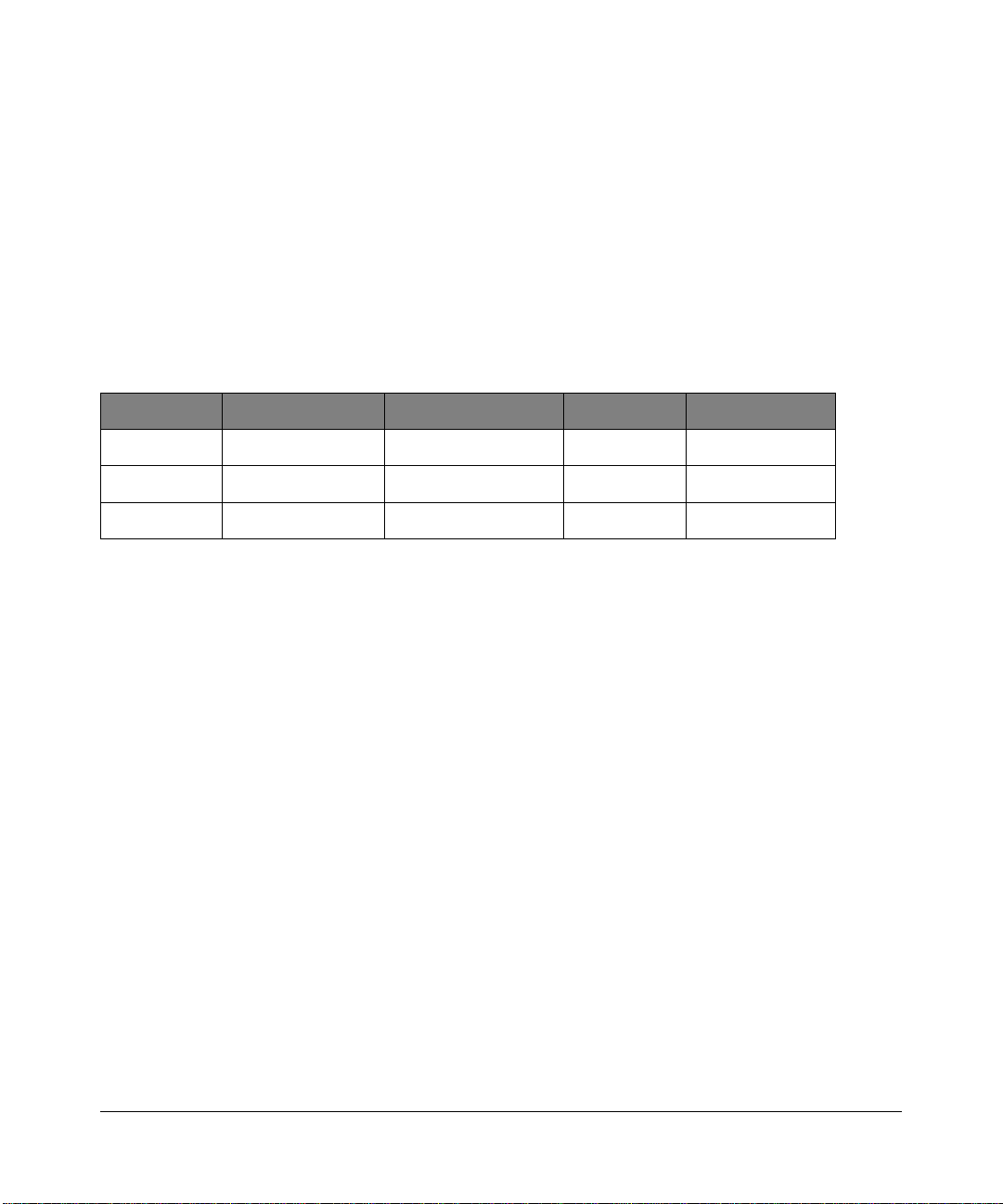
Antenna Statement for North America and Australia
In addition to its own 2 antennas, the WG302 device has been approved for use with the following detachable antennas
and antenna cables:
Approved
Antennas
NETGEAR
ANT24D18
NETGEAR
ANT2409
NETGEAR
ANT24O5
*WG302 maximum radiated power in North America and Australia: 20 dBm – cable loss + antenna gain
Please go to www.netgear.com/go/wg302_fcc for an updated list of wireless accessories approved to be used with the
WG302 in North America and Australia.
Antenna Gain and
type
18 dBi, directional
outdoor/indoor
9 dBi, omnidirectional
outdoor/indoor
5 dBi, ceiling/wall
indoor
Approved Antenna
Cable
NETGEAR
ACC-10314-01 thru 05
NETGEAR
ACC-10314-01 thru 05
NETGEAR
ACC-10314-01 thru 05
Antenna Cable
Length
1.5 m to 30 m 19 dBm + 18 dBi ant.
1.5 m to 30 m 19 dBm + 9 dBi ant.
1.5 m to 30 m 19 dBm + 5 dBi ant.
Maximum
Transmitted Power
Industry Canada Compliance Statement
This Class B Digital apparatus meets all the requirements of the Canadian Interference Causing Equipment Regulations
ICES 003.
Cet appareil numerique de classe B respecte les exigences du reglement du Canada sur le materiel brouilleur NMB-003.
The device is certified to the requirements of RSS-210 for 2.4 GHz spread spectrum devices. The use of this device in a
system operating either partially or completely outdoors may require the user to obtai n a license for the sys tem according
to the Canadian regulations. For further information, contact your local Industry Canada office.
iv
v4.0, May 12, 2006
Page 5

Europe – EU Declaration of Conformity
Marking by the above symbol indicates compliance with the Essential Requirements of the R&TTE Directive of the
European Union (1999/5/EC). This equipment meets the following conformance standards:
EN300 328, EN301 489-17, EN60950
Europe – Declaration of Conformity in Languages of the European Community
Èesky [Czech] NETGEAR Inc. tímto prohlašuje, _e tento Radiolan je ve shodě se základními
po_adavky a dalšími příslušnými ustanoveními směrnice 1999/5/ES.
Dansk [Danish] Undertegnede NETGEAR Inc. erklærer herved, at følgende udstyr Radiolan overholder
de væsentlige krav og øvrige relevante krav i direktiv 1999/5/EF.
Deutsch
[German]
Eesti
[Estonian]
English Hereby, NETGEAR Inc., declares that this Radiolan is in compliance with the essential
Español
[Spanish]
ЕллзнйкЮ
[Greek]
Français
[French]
Italiano [Italian] Con la presente NETGEAR Inc. dichiara che questo Radiolan è conforme ai requisiti
Latviski
[Latvian]
Lietuviø
[Lithuanian]
Hiermit erklärt NETGEAR Inc., dass sich das Gerät Radiolan in Übereinstimmung mit
den grundlegenden Anforderungen und den übrigen einschlägigen Bestimmungen der
Richtlinie 1999/5/EG befindet.
Käesolevaga kinnitab NETGEAR Inc. seadme Radiolan vastavust direktiivi 1999/5/EÜ
põhinõuetele ja nimetatud direktiivist tulenevatele teistele asjakohastele sätetele.
requirements and other relevant provisions of Directive 1999/5/EC.
Por medio de la presente NETGEAR Inc. declara que el Radiolan cumple con los
requisitos esenciales y cualesquiera otras disposiciones aplicables o exigibles de la
Directiva 1999/5/CE.
ΜΕ ΤΗΝ ΠΑΡΟΥΣΑ NETGEAR Inc. ΔΗΛΩΝΕΙ ΟΤΙ Radiolan ΣΥΜΜΟΡΦΩΝΕΤΑΙ
ΠΡΟΣ ΤΙΣ ΟΥΣΙΩΔΕΙΣ ΑΠΑΙΤΗΣΕΙΣ ΚΑΙ ΤΙΣ ΛΟΙΠΕΣ ΣΧΕΤΙΚΕΣ ΔΙΑΤΑΞΕΙΣ ΤΗΣ
ΟΔΗΓΙΑΣ 1999/5/ΕΚ.
Par la présente NETGEAR Inc. déclare que l'appareil Radiolan est conforme aux
exigences essentielles et aux autres dispositions pertinentes de la directive 1999/5/CE.
essenziali ed alle altre disposizioni pertinenti stabilite dalla direttiva 1999/5/CE.
Ar šo NETGEAR Inc. deklarē, ka Radiolan atbilst Direktī
prasībām un citiem ar to saistītajiem noteikumiem.
Šiuo NETGEAR Inc. deklaruoja, kad šis Radiolan atitinka esminius reikalavimus ir kitas
1999/5/EB Direktyvos nuostatas.
vas 1999/5/EK būtiskajām
Nederlands
[Dutch]
Malti [Maltese] Hawnhekk, NETGEAR Inc., jiddikjara li dan Radiolan jikkonforma mal-htigijiet essenzjali
Hierbij verklaart NETGEAR Inc. dat het toestel Radiolan in overeenstemming is met de
essentiële eisen en de andere relevante bepalingen van richtlijn 1999/5/EG.
u ma provvedimenti ohrajn relevanti li hemm fid-Dirrettiva 1999/5/EC.
v4.0, May 12, 2006
v
Page 6

Magyar
[Hungarian]
Polski [Polish] Niniejszym NETGEAR Inc. oświadcza, że Radiolan jest zgodny z zasadniczymi
Alulírott, NETGEAR Inc. nyilatkozom, hogy a Radiolan megfelel a vonatkozó alapvetõ
követelményeknek és az 1999/5/EC irányelv egyéb elõírásainak.
wymogami oraz pozostałymi stosownymi postanowieniami Dyrektywy 1999/5/EC.
Português
[Portuguese]
Slovensko
[Slovenian]
Slovensky
[Slovak]
Suomi [Finnish] NETGEAR Inc. vakuuttaa täten että Radiolan tyyppinen laite on direktiivin 1999/5/EY
Svenska
[Swedish]
Íslenska
[Icelandic]
Norsk
[Norwegian]
NETGEAR Inc. declara que este Radiolan está conforme com os requisitos essenciais
e outras disposições da Directiva 1999/5/CE.
NETGEAR Inc. izjavlja, da je ta Radiolan v skladu z bistvenimi zahtevami in ostalimi
relevantnimi določili direktive 1999/5/ES.
NETGEAR Inc. týmto vyhlasuje, _e Radiolan spĺňa základné po_iadavky a všetky
príslušné ustanovenia Smernice 1999/5/ES.
oleellisten vaatimusten ja sitä koskevien direktiivin muiden ehtojen mukainen.
Härmed intygar NETGEAR Inc. att denna Radiolan står I överensstämmelse med de
väsentliga egenskapskrav och övriga relevanta bestämmelser som framgår av direktiv
1999/5/EG.
Hér með lýsir NETGEAR Inc. yfir því að Radiolan er í samræmi við grunnkröfur og aðrar
kröfur, sem gerðar eru í tilskipun 1999/5/EC.
NETGEAR Inc. erklærer herved at utstyret Radiolan er i samsvar med de
grunnleggende krav og øvrige relevante krav i direktiv 1999/5/EF.
Countries of Operation & Conditions of Use in the European Community
This device is intended to be operated in all countries of the European Community. Requirements for indoor vs. outdoor
operation, license requirements and allowed channels of operation apply in some countries as described below.
Note: The user must use the configuration utility provided with this product to ensure the channels of operation
are in conformance with the spectrum usage rules for European Community countries as described below.
This device requires that the user or installer properly enter the current country of operation in the 5GHz Radio
Configuration Window as described in the user guide, before operating this device.
This device will automatically limit the allowable channels determined by the current country of operation. Incorrectly
entering the country of operation may result in illegal operation and may cause harmful interference to other system.
The user is obligated to ensure the device is operating according to the channel limitations, indoor/outdoor restrictions
and license requirements for each European Community country as described in this document.
This device employs a radar detection feature required for European Community operation in the 5GHz band. This
feature is automatically enabled when the country of operation is correctly configured for any European Community
country. The presence of nearby radar operation may result in temporary interruption of operation of this device. The
radar detection feature will automatically restart operation on a channel free of radar.
The 5GHz Turbo Mode feature is not allowed for operation in any European Community country. The current setting
for this feature is found in the 5GHz Radio Configuration Window as described in the user guide.
vi
v4.0, May 12, 2006
Page 7
This device may be operated indoors or outdoors in all countries of the European Community using the 2.4GHz band:
Channels 1 – 13, except where noted below:
•In Italy the end-user must apply for a license from the national spectrum authority to operate this device outdoors.
•In France outdoor operation is only permitted using the 2.4 – 2.454 GHz band: Channels 1 – 7.
• Belgium requires notifying spectrum agency if deploying >300meter wireless links in outdoor public areas using
2.4GHz band.
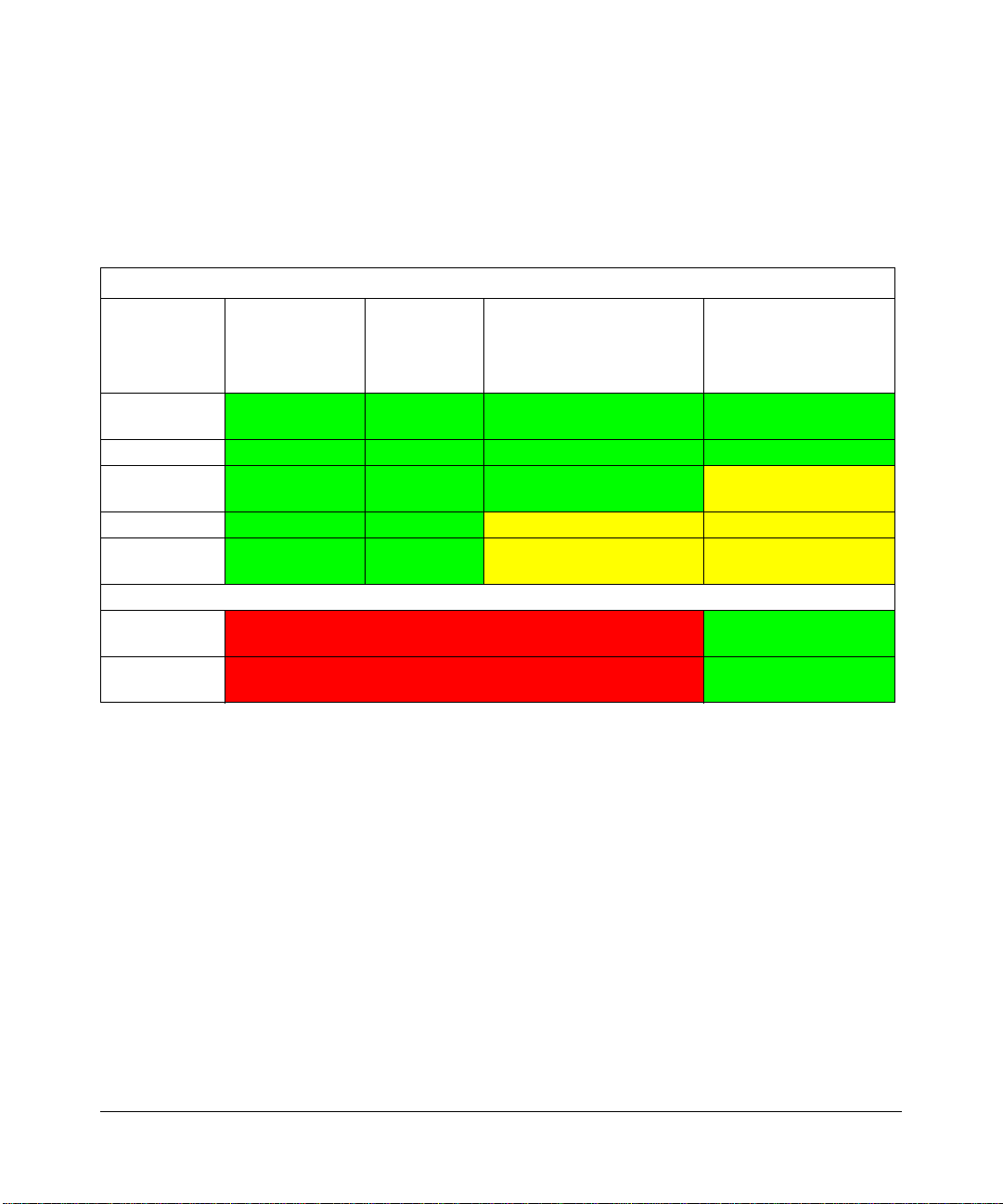
European Spectrum Usage Rules - Effective April 11, 2006
5.15-5.25 (GHz)
Country
Channels:
36,40,44,48
ALL EC
Countries
Belgium Indoor Only Indoor Only Indoor or Outdoor Indoor or Outdoor !
France
Greece Indoor Only Indoor Only Indoor Only Indoor Only
Italy
Indoor Only Indoor Only Indoor or Outdoor Indoor or Outdoor
Indoor Only Indoor Only Indoor or Outdoor Indoor Ch. 1-13
Indoor Only Indoor Only Indoor
5.25-5.35
(GHz)
Channels:
52,56,60,64
5.47-5.725 (GHz)
Channels:
100,104,108,112,116,
120,124,128,132,136,140
(Outdoor w/License)
2.4-2.4835 (GHz)
Channels: 1 to 13
(Except Where Noted)
Outdoor 1-7 Only
Indoor (Outdoor w/
License)
Turbo Mode
AdHoc Mode Not Allowed Same 2.4 GHz rules as
Not Allowed in 5GHz Same 2.4 GHz rules as
above
above
Product and Publication Details
Model Number: WG302
Publication Date: April 2006
Product Family: wireless access point
Product Name: ProSafe 802.11g Wireless Access Point WG302
Home or Business Product: Business
Language: English
Publication Part Number: 202-10008-04
v4.0, May 12, 2006
vii
Page 8

viii
v4.0, May 12, 2006
Page 9

Contents
About This Manual
Audience, Scope, Conventions, and Formats .................................................................xiii
How to Use This Manual .................................................................................................xiv
How to Print this Manual ..................................................................................................xiv
Chapter 1
Introduction
About the ProSafe 802.11g Wireless Access Point .......................................................1-1
Key Features and Standards ..........................................................................................1-2
Supported Standards and Conventions ...................................................................1-2
Key Features ............................................................................................................1-2
802.11g Standards-based Wireless Networking ......................................................1-4
Autosensing Ethernet Connections with Auto Uplink ...............................................1-4
Compatible and Related NETGEAR Products ................................................................1-5
System Requirements ....................................................................................................1-5
Package Contents ..........................................................................................................1-5
Hardware Description .....................................................................................................1-6
Chapter 2
Basic Installation and Configuration
Wireless Equipment Placement and Range Guidelines .................................................2-1
Cabling Requirements ..............................................................................................2-2
Default Factory Settings ...........................................................................................2-2
Understanding WG302 Wireless Security Options .........................................................2-3
Installing the ProSafe 802.11g ........................................................................................2-4
Step 1: Set up the ProSafe 802.11g .........................................................................2-4
Step 2: Configure LAN and Wireless Access ...........................................................2-4
Step 3: Deploy the ProSafe 802.11g ........................................................................2-7
Step 4: Verify Wireless Connectivity .........................................................................2-8
Logging in Using the Default IP Address ........................................................................2-8
v4.0, April 2006
ix
Page 10

Setting Basic IP Options .................................................................................................2-9
Configuring Wireless Settings ...................................................................................... 2-11
Setting Up and Testing Basic Wireless Connectivity ....................................................2-13
Understanding Security Profiles ...................................................................................2-14
SSID and WEP Settings Setup Form .....................................................................2-19
Configuring RADIUS Server Settings (if required) .................................................2-21
Setting up A Security Profile ..................................................................................2-23
Configuring WEP .............................................................................................2-24
Configuring WPA with RADIUS .......................................................................2-25
Configuring WPA-PSK .....................................................................................2-26
Configuring WPA2 with RADIUS .....................................................................2-27
Configuring WPA2-PSK ...................................................................................2-28
Configuring WPA and WPA2 with RADIUS .....................................................2-29
Configuring WPA-PSK and WPA2-PSK ...........................................................2-30
Restricting Wireless Access by MAC Address .......................................................2-31
Chapter 3
Management
Remote Management .....................................................................................................3-1
Accessing the WG302 over a Secure Telnet Interface .............................................3-2
CLI Commands ........................................................................................................3-3
Using Syslog and Activity Log Information .....................................................................3-3
Viewing General Summary Information ..........................................................................3-4
Viewing Network Traffic Statistics ...................................................................................3-7
Viewing Available Wireless Station Statistics ..................................................................3-9
Upgrading the Wireless Access Point Firmware ............................................................3-9
Configuration File Management ................................................................................... 3-11
Saving and Retrieving the Configuration ................................................................ 3-11
Restoring the WG302 to the Factory Default Settings ...........................................3-12
Changing the Administrator Password .........................................................................3-12
Chapter 4
Advanced Configuration
IP Settings for Wireless Clients ......................................................................................4-1
Hotspot Settings .............................................................................................................4-3
Advanced Wireless Settings ...........................................................................................4-3
Wireless Bridge and Repeater Modes ............................................................................4-5
x
v4.0, April 2006
Page 11

Configuring a Point-to-Point Bridge ..........................................................................4-6
Configuring a Multi-Point Bridge ..............................................................................4-7
Configuring Wireless Repeater Mode ......................................................................4-9
Chapter 5
Troubleshooting
No lights are lit on the access point. ...............................................................................5-1
The Wireless LAN activity light does not light up. ...........................................................5-2
The LAN light is not lit. ....................................................................................................5-2
I cannot access the Internet or the LAN with a wireless capable computer. .................5-2
I cannot connect to the WG302 to configure it. ..............................................................5-3
When I enter a URL or IP address I get a timeout error. ................................................5-3
Using the Reset Button to Restore Factory Default Settings ..........................................5-3
Appendix A
Factory Defaults and
Technical Specifications
Factory Default Settings ................................................................................................ A-1
Technical Specifications ................................................................................................ A-3
Appendix B
Related Documents
Appendix C
Command Line Reference
Command Sets .............................................................................................................. C-1
v4.0, April 2006
xi
Page 12

xii
v4.0, April 2006
Page 13
About This Manual
The NETGEAR ProSafe 802.11g Wireless Access Point WG302 Reference Manual describes how
to install, configure, and troubleshoot the NETGEAR ProSafe 802.11g Wireless Access Point. The
information in this manual is intended for readers with intermediate computer and Internet skills.
Audience, Scope, Conventions, and Formats
This reference manual assumes that the reader has basic to intermediate computer and Internet
skills. However, basic computer network, Internet, firewall, and VPN technologies tutorial
information is provided in the Appendices and on the NETGEAR website.
• Typographical conventions.This manual uses the following typographical conventions:
italics Emphasis, books, CDs, URL names
bold User input
fixed Screen text, file and server names, extensions, commands, IP addresses
• Formats.This guide uses the following formats to highlight special messages:
Note: This format is used to highlight information of importance or special interest.
Tip: This format is used to highlight a procedure that will save time or resources.
Warning: Ignoring this type of note may result in a malfunction or damage to the
equipment.
v4.0, April 2006
xiii
Page 14
NETGEAR ProSafe 802.11g Wireless Access Point WG302 Reference Manual
Danger: This is a safety warning. Failure to take heed of this notice may result in
personal injury or death.
• Scope. This manual is written for the ProSafe 802.11g according to these specifications:
Product Version ProSafe 802.11g Wireless Access Point
Manual Publication Date April 2006
Product updates are available on the NETGEAR, Inc. Web site at
http://kbserver.netgear.com/products/WG302.asp.
How to Use This Manual
The HTML version of this manual includes the following:
• Buttons, and , for browsing forwards or backwards through the manual one page
at a time
• A button that displays the table of contents and an button. Double-click on a
link in the table of contents or index to navigate directly to where the topic is described in the
manual.
• A button to access the full NETGEAR, Inc. online knowledge base for the product
model.
• Links to PDF versions of the full manual and individual chapters.
How to Print this Manual
To print this manual you can choose one of the following options, according to your needs.Your
computer must have the free Adobe Acrobat Reader installed in order to view and print PDF files.
The Acrobat Reader is available on the Adobe website at http://www.adobe.com.
• Printing a Page in the HTML View. Each page in the HTML version of the manual is
dedicated to a major topic. Use the Print button on the browser toolbar to print the page
contents.
• Printing a Chapter. Use the PDF of This Chapter link at the top left of any page.
xiv
v4.0, April 2006
Page 15
NETGEAR ProSafe 802.11g Wireless Access Point WG302 Reference Manual
– Click the PDF of This Chapter link at the top right of any page in the chapter you want to
print. The PDF version of the chapter you were viewing opens in a browser window.
– Click the print icon in the upper left of the window.
Tip: If your printer supports printing two pages on a single sheet of paper, you can
save paper and printer ink by selecting this feature
• Printing the Full Manual. Use the Complete PDF Manual link at the top left of any page.
– Click the Complete PDF Manual link at the top left of any page in the manual. The PDF
version of the complete manual opens in a browser window.
– Click the print icon in the upper left of the window.
Tip: If your printer supports printing two pages on a single sheet of paper, you can
save paper and printer ink by selecting this feature.
v4.0, April 2006
xv
Page 16

NETGEAR ProSafe 802.11g Wireless Access Point WG302 Reference Manual
xvi
v4.0, April 2006
Page 17

Chapter 1
Introduction
This chapter introduces the NETGEAR® ProSafe™ Wireless Access Point 802.11g WG302 and
gives an overview of some of the key features contained in this product. The minimum installation
prerequisites are presented in “System Requirements” on page 1-5. What’s is the box is listed in
“Package Contents” on page 1-5, followed by a description of the hardware functionality in
“Hardware Description” on page 1-6.
About the ProSafe 802.11g Wireless Access Point
The ProSafe 802.11g Wireless Access Point is the basic building block of a wireless LAN
infrastructure. It provides connectivity between Ethernet wired networks and radio-equipped
wireless notebook systems, desktop systems, print servers, and other devices.
The WG302 provides wireless connectivity to multiple wireless network devices within a fixed
range or area of coverage, interacting with a wireless network interface card (NIC) via an antenna.
T ypically, an individual in-building access point provides a maximum connectivity area with about
a 300 foot radius. The ProSafe 802.11g Wireless Access Point can support a small group of users
in a range of several hundred feet. Most access points are rated between 30-70 users,
simultaneously.
The ProSafe 802.11g Wireless Access Point acts as a bridge between the wired LAN and wireless
clients. Connecting multiple ProSafe 802.11gs via a wired Ethernet backbone can further lengthen
the wireless network coverage. As a mobile computing device moves out of the range of one
access point, it moves into the range of another. As a result, wireless clients can freely roam from
one Access Point to another and still maintain seamless connection to the network.
The auto-sensing capability of the ProSafe 802.11g Wireless Acces s Point allows packet
transmission at up to 108 Mbps, or at reduced speeds to compensate for distance or
electromagnetic interference.
1-1
v4.0, April 2006
Page 18

NETGEAR ProSafe 802.11g Wireless Access Point WG302 Reference Manual
Key Features and Standards
The ProSafe 802.11g is easy-to-use and provides solid wireless and networking support. It also
offers a wide range of security options.
Supported Standards and Conventions
The following standards and conventions are supported:
• Standards Compliant. The Wireless Access Point complies with the IEEE 802.11g for
Wireless LANs.
• WEP support. Support for WEP is included. 64-bit, 128-bit, and 152-bit keys are supported.
• Full WPA and WPA2 support. WPA and WPA2 enterprise class strong security with
RADIUS and certificate authentication as well as dynamic encryption key generation. WPAPSK and WPA2-PSK pre-shared key authentication without the overhead of RADIUS servers
but with all of the strong security of WPA.
• DHCP Client Support. DHCP provides a dynamic IP address to PCs and other devices upon
request. The WG302 can act as a client and obtain information from your DHPC server.
• Multiple BSSIDs. Support for multiple BSSIDs. When one AP is connected to a wired
network and a set of wireless stations it is referred to as a Basic Service Set (BSS). The Basic
Service Set Identifier (BSSID) is a 32-character unique identifier attached to the header of
packets sent over a WLAN that differentiated one WLAN from another when a mobile device
tries to connect to the network.
• SNMP Support. Support for Simple Network Management Protocol (SNMP) Management
Information Base (MIB) management.
• 802.11Q VLAN (Virtual Wireless LAN) Support. A network of computers that behave as if
they are connected to the same network even though they actually may be physically located
on different segments of a LAN. VLANs are configured through software rather than
hardware, which makes them extremely flexible. VLANs are very useful for user/host
management, bandwidth allocation and resource optimization.
Key Features
The NETGEAR WG302 provides solid functionality, including these features:
• Multiple Operating Modes
– Wireless Access Point – Operates as a standard 802.11g.
1-2 Introduction
v4.0, April 2006
Page 19

NETGEAR ProSafe 802.11g Wireless Access Point WG302 Reference Manual
– Point-to-Point Bridge – In this mode, the WG302 only communicates with another bridge-
mode wireless station. You must enter the MAC address (physical address) of the other
bridge-mode wireless station in the field provided. WEP should be used to protect this
communication.
– Point-to-Multi-Point Bridge – Select this only if this WG302 is the “Master” for a group of
bridge-mode wireless stations. The other bridge-mode wireless stations must be set to
Point-to-Point Bridge mode, using this WG302's MAC address. They then send all traffic
to this “Master”, rather than communicate directly with each other . WEP should be used to
protect this traffic.
– Wireless Repeater – In this half-duplex mode, the WG302 only communicates with
another repeater-mode wireless station. You must enter the MAC address of both adjacent
repeater-mode wireless stations in the fields provided. WEP should be used to protect this
communication.
• Wireless Multimedia (WMM) support. WMM is a subset of the 802.11e standard. WMM
allows wireless traffic to have a range of priorities, depending on the kind of data. Timedependent information such as video or audio will have a higher priority than normal traffic.
For WMM to function correctly, wireless clients must also support WMM.
• Rogue Access Point detection. For enhanced security, you can scan the wireless network to
detect rogue access points.
• Hotspot settings. You can allow all HTTP (TCP, port 80) requests to be captured and redirected to the URL you specify.
• Upgradeable Firmware. Firmware is stored in a flash memory and can be upgraded easily,
using only your Web browser, and can be upgraded remotely.
• Access Control. The Access Control MAC address filtering feature can ensure that only
trusted wireless stations can use the WG302 to gain access to your LAN.
• Simple Configuration. If the default settings are unsuitable, they are easy to change.
• Hidden Mode. The SSID is not broadcast, assuring only clients configured with the correct
SSID can connect.
• Secure Telnet Command Line Interface. The Telnet command line interface enables direct
access over the serial port and easy scripting of configuration of multiple WG302 across an
extensive network via the Ethernet interface. An SSH client is required.
• Configuration Backup. Configuration settings can be backed up to a file and restored.
• Secure and Economical Operation. Adjustable power output allows more secure or
economical operation.
Introduction 1-3
v4.0, April 2006
Page 20

NETGEAR ProSafe 802.11g Wireless Access Point WG302 Reference Manual
• Power over Ethernet. Power can be supplied to the WG302 over the Ethernet port from any
802.3af compliant mid-span or end-span source such as the NETGEAR FSM7326P Managed
Power over Ethernet Layer 3 managed switch.
• Autosensing Ethernet Connection with
IEEE 802.3 Ethernet networks.
• LED Indicators. Power, test, LAN speed, LAN activity, and wireless activity are easily
identified.
• VLAN Security Profiles. Each Security Profile is automatically allocated a VLAN ID when
the Security Profile is configured.
Auto Uplink Interface. Connects to 10/100 Mbps
802.11g Standards-based Wireless Networking
The ProSafe 802.11g Wireless Access Point provides a bridge between Ethernet wired LANs and
802.11g compatible wireless LAN networks. It provides connectivity between Ethernet wired
networks and radio-equipped wireless notebook systems, desktop systems, print servers, and other
devices. Additionally, the WG302 supports the following wireless features:
• Distributed coordinated function (CSMA/CA, Back off procedure, ACK procedure,
retransmission of unacknowledged frames)
• RTS/CTS handshake
• Beacon generation
• Packet fragmentation and reassembly
• Short or long preamble
• Roaming among access points on the same subnet
Autosensing Ethernet Connections with Auto Uplink
The WG302 can connect to a standard Ethernet network. The LAN interface is autosensing and
capable of full-duplex or half-duplex operation.
The wireless access point incorporates Auto Uplink
automatically sense whether the Ethernet cable plugged into the port should have a “normal”
connection such as to a computer or an “uplink” connection such as to a switch or hub. That port
will then configure itself to the correct configuration. This feature also eliminates any concerns
about crossover cables, as Auto Uplink will accommodate either type of cable to make the right
connection.
1-4 Introduction
v4.0, April 2006
TM
technology. The Ethernet port will
Page 21

NETGEAR ProSafe 802.11g Wireless Access Point WG302 Reference Manual
Compatible and Related NETGEAR Products
For a list of compatible products from other manufacturers, see the Wireless Ethernet
Compatibility Alliance Web site (WECA, see http://www.wi-fi.net).
The following NETGEAR products work with the ProSafe 802.11g:
• WAG511 ProSafe 108 Mbps Dual Band PC Card
• WAG311 ProSafe 108 Mbps Dual Band PCI Card
• WG311T 802.11 g 108 Mbps Wireless PCI Card
• WG511T 802.11 g 108 Mbps Wireless CardBus Adapter
• WG511 802.11g 54 Mbps Wireless CardBus Adapter
• WG111 801.11g 54 Mbps Wireless USB Adapter
System Requirements
Before installing the WG302, make sure your system meets these requirements:
• A 10/100 Mbps Local Area Network device such as a hub or switch
• The Category 5 UTP straight through Ethernet cable with RJ-45 connector included in the
package, or one like it
• A 100-240 V, 50-60 HZ AC power source
• A Web browser for configuration such as Microsoft Internet Explorer 6.0 or above, or
Netscape Navigator 4.78 or above
• At least one computer with the TCP/IP protocol installed
• 802.11b- or 802.11g-compliant devices, such as the NETGEAR WG511 Wireless Adapter
Package Contents
The product package should contain the following items:
• ProSafe 802.11g Wireless Access Point
• Power adapter and cord (12 V dc, 1.2 A)
Introduction 1-5
v4.0, April 2006
Page 22
NETGEAR ProSafe 802.11g Wireless Access Point WG302 Reference Manual
• Straight through Category 5 Ethernet cable WG302 802.11g ProSafe Wireless Access Point
Installation Guide
• Resource CD which includes this manual.
• Support Registration card
Contact your reseller or customer support in your area if there are any missing or damaged parts.
You can refer to the Support Information Card for the telephone number of customer support in
your area. You should keep the Support Information card, along with the original packing
materials, and use the packing materials to repack the WG302 if you need to return it for repair. T o
qualify for product updates and product warranty registrations, we encourage you to register on the
NETGEAR Web site at: http://www.NETGEAR.com.
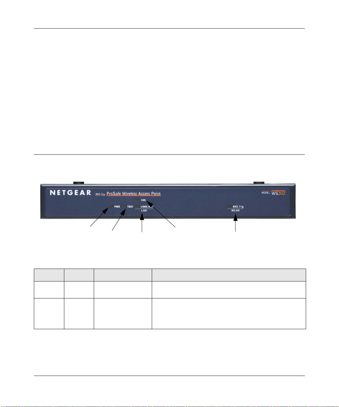
Hardware Description
The WG302 front hardware functions are described below:
Figure 1-1
1
2
3
4
5
The following table explains the LED indicators:
Number LED Activity DESCRIPTION
1 Power Off
On (Green)
2 Test Blinking Self Test Indicator
1-6 Introduction
No power is supplied to the wireless access point.
Power is supplied to the wireless access point.
Indicates self test, loading software, or system fault (if
continues).
Note: This LED may blink for a minute before going off.
v4.0, April 2006
Page 23
NETGEAR ProSafe 802.11g Wireless Access Point WG302 Reference Manual
Number LED Activity DESCRIPTION
3 Local
Port
4 Internet
Port
5 Wireless 802.11gWLAN
Link/Act LAN
Off
On (Green)
Blink (Green)
On (Amber)
Blink (Amber
100 LED
Off
On (Green)
Off
On (Green)
Blinking (Green)
Ethernet LAN Link Activity Indicator
Indicates no Ethernet link detected.
100 Mbps Fast Ethernet link detected, no activity.
Indicates data traffic on the 100Mbps Ethernet LAN.
10 Mbps Ethernet link detected, no activity.
Indicates data traffic on the 10Mbps Ethernet LAN.
Ethernet LAN Speed Indicator
Indicates 10 Mbps Ethernet link detected
100 Mbps Fast Ethernet link detected.
Wireless LAN Link Activity Indicator
Indicates no wireless link activity.
Wireless link activity.
Data is being transmitted or received.
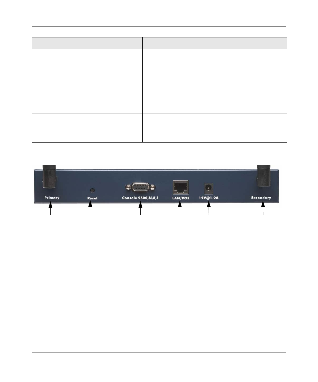
The WG302 rear hardware functions are described below:
1
2
3
4
5
1
Figure 1-2
The rear panel contains the following elements:
1. Left and Right Detachable Antenna
The WG302 provides two detachable antenna.
2. Restore to Factory Defaults Button
The restore to default button located between the Ethernet RJ-45 connector and the power
socket restores the WG302 to the factory default settings.
3. Serial Console Port
Male DB-9 serial port for serial DTE connections.
4. RJ-45 Ethernet Port
Introduction 1-7
v4.0, April 2006
Page 24

NETGEAR ProSafe 802.11g Wireless Access Point WG302 Reference Manual
Use the WG302 Ethernet RJ-45 port to connect to an Ethernet LAN through a device such as a
hub, switch, router, or POE switch.
5. Power Socket
This socket connects to the WG302 12V 1.2A power adapter.
1-8 Introduction
v4.0, April 2006
Page 25
Chapter 2
Basic Installation and Configuration
This chapter describes how to set up your ProSafe 802.11g Wireless Acce ss Point for wireless
connectivity to your LAN. This basic configuration will enable computers with 802.11b or
802.11g wireless adapters to do such things as connect to the Internet, or access printers and files
on your LAN.
Note: Indoors, computers can connect over 802.11g wireless networks at ranges of
several hundred feet or more. This distance can allow for others outside your area
to access your network. It is important to take appropriate steps to secure your
network from unauthorized access. The ProSafe 802.11g provides highly effective
security features which are covered in detail in “Setting Up and Testing Basic
Wireless Connectivity” on page 2-13. Deploy the security features appropriate to
your needs.
You need to prepare these three things before you can establish a connection through your wireless
access point:
• A location for the WG302 that conforms to the “Wireless Equipment Placement and Range
Guidelines” below .
• The wireless access point connected to your LAN through a device such as a hub, switch,
router, or Cable/DSL gateway.
• One or more computers with properly configured 802.11b or 802.11g wireless adapters.
Wireless Equipment Placement and Range Guidelines
The operating distance or range of your wireless connection can vary significantly bas ed on the
physical placement of the wireless access point. The latency, data throughput performance, and
notebook power consumption of wireless adapters also vary depending on your configuration
choices.
v4.0, April 2006
2-1
Page 26
NETGEAR ProSafe 802.11g Wireless Access Point WG302 Reference Manual
Note: Failure to follow these guidelines can result in significant performance degradation
or inability to wirelessly connect to the WG302. For complete performance
specifications, see Appendix A, “Factory Defaults and Technical Specifications”.
For best results, place your wireless access point:
• Near the center of the area in which your PCs will operate.
• In an elevated location such as a high shelf where the wirelessly connected PCs have line-ofsight access (even if through walls).
• Away from sources of interference, such as PCs, microwaves, and 2.4 GHz cordless phones.
• Away from large metal surfaces.
• Putting the antenna in a vertical position provides best side-to-side coverage. Putting the
antenna in a horizontal position provides best up-and-down coverage.
• If using multiple access points, it is better if adjacent access points use different
Channels to reduce interference. The recommended Channel spacing between adjacent access
points is 5 Channels (for example, use Channels 1 and 6, or 6 and 11).
The time it takes to establish a wireless connection can vary depending on both your security
settings and placement. WEP connections can take slightly longer to establish. Also, WEP
encryption can consume more battery power on a notebook computer.
radio frequency
Cabling Requirements
The ProSafe 802.11g connects to your LAN via twisted-pair Category 5 Ethernet cable with RJ-45
connectors.
Default Factory Settings
When you first receive your WG302, the default factory settings will be set. You can restore these
defaults with the Factory Default Restore switch on the rear panel—see Figure 1-1 on page 1-6.To
restore your default settings, see Appendix A, “Factory Defaults and Technical Specifications” for
a list of the default settings and instructions on the use of the restore switch.
2-2 Basic Installation and Configuration
v4.0, April 2006
Page 27
NETGEAR ProSafe 802.11g Wireless Access Point WG302 Reference Manual
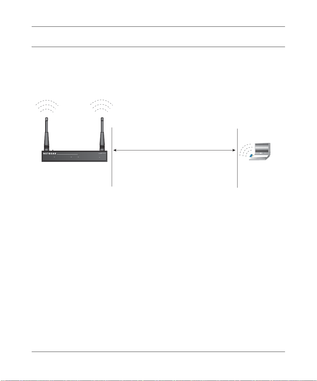
Understanding WG302 Wireless Security Options
Your wireless data transmissions can be received well beyond your walls by anyone with a
compatible adapter. For this reason, use the security features of your wireless equipment. The
ProSafe 802.11g provides highly effective security features which are covered in detail in this
chapter. Deploy the security features appropriate to your needs.
:LUHOHVV'DWD
6HFXULW\2SWLRQV
WG302
5DQJH8SWR)RRW5DGLXV
B
0RO3AFE7IRELESS!CCESS0OINT
3:5 /$1
:LUHOHVV/$1
Figure 2-1: WG302 wireless data security options
There are several ways you can enhance the security of your wireless network:
• Restrict Access Based on MAC address. You can restrict access to only trusted PCs so that
unknown PCs cannot wirelessly connect to the WG302. MAC address filtering adds an
obstacle against unwanted access to your network, but the data broadcast over the wireless link
is fully exposed.
• Turn Off the Broadcast of the Wireless Network Name (SSID). If you disable broadcast of
the SSID, only devices that have the correct SSID can connect. This nullifies the wireless
network “discovery” feature of some products such as Windows XP, but the data is still fully
exposed to a determined snoop using specialized test equipment like wireless sniffers.
• Use WEP. Wired Equivalent Privacy (WEP) data encryption provides data security. WEP
Shared Key authentication and WEP data encryption will block all but the most determined
eavesdropper.
• Use WPA, WPA-PSK, WPA2, or WPA2-PSK. Wi-Fi Protected Access (WPA and WPA2)
data encryption provides data security . The very strong authentication along with dyn amic per
frame rekeying of WPA make it virtually impossible to compromise. Because this is a new
standard, wireless device driver and software availability may be limited.
-/$%,
-%
.O3ECURITY%ASYBUTNOSECURITY
-!#!CCESS,IST.ODATASECURITY
7%03ECURITYBUTVULNERABLE
70!OR70!03+6ERYSTRONGSECURITY
Basic Installation and Configuration 2-3
v4.0, April 2006
Page 28
NETGEAR ProSafe 802.11g Wireless Access Point WG302 Reference Manual
Installing the ProSafe 802.11g
Before installing the ProSafe 802.11g Wireless Access Point , you should make sure that your
Ethernet network is up and working. You will be connecting the access point to the Ethernet
network so that computers with 802.11b or 802.11g wireless adapters will be able to communicate
with computers on the Ethernet network. In order for this to work correctly, verify that you have
met all of the system requirements, shown in “System Requirements” on page 1-5.
Step 1: Set up the ProSafe 802.11g
Tip: Before mounting the WG302 in a high location, first set up and test the WG302 to
verify wireless network connectivity.
1. Prepare a computer with an Ethernet adapter. If this computer is already part o f yo ur network ,
record its TCP/IP configuration settings.
2. Configure the computer with a static IP address of 192.168.0.210 and 255.255.255.0 for the
Subnet Mask.
3. Connect an Ethernet cable from the WG302 to the computer.
4. Connect the power adapter to the WG302 and verify the following:
• The PWR power light goes on.
• The LAN light of the wireless access point is lit when connected to a powered on
computer.
Step 2: Configure LAN and Wireless Access
To configure the WG302 Ethernet port for LAN access :
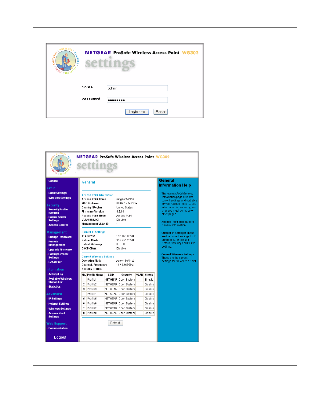
1. Connect to the WG302 by opening your browser and entering http://192.168.0.228 in the
address field. A login window like the one shown below will open:
2. When prompted, enter admin for the user name and password for the password, both in lower
case letters.
Note: If there is no activity for 5 minutes, the wireless access point will
automatically log you out
2-4 Basic Installation and Configuration
v4.0, April 2006
Page 29
NETGEAR ProSafe 802.11g Wireless Access Point WG302 Reference Manual
.
Figure 2-1.WG302 Login and General settings screen
3. Click Login Now. The Web browser displays the WG302 main menu and General page.
Figure 2-2.
Basic Installation and Configuration 2-5
v4.0, April 2006
Page 30
NETGEAR ProSafe 802.11g Wireless Access Point WG302 Reference Manual
• Select the Documentation link under the Web Support menu to view support information
or the documentation for the wireless access point.
• Click Logout to exit the user interface (the wireless access point will wait 5 minutes after
no activity before it automatically logs you out.
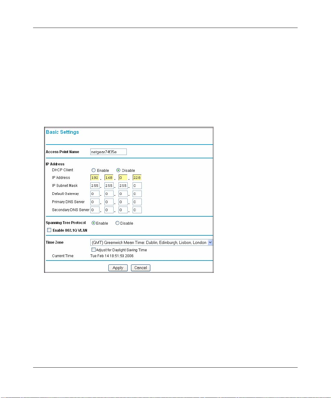
4. Select Basic Settings to view the Basic Settings menu and configure the settings appropriate
for your network (The default settings are usually adequate for most situations; see “Setting
Basic IP Options” on page 2-9 for guidance on changing these settings).
5. Enable 802.1Q VLAN, if required. (This option is only useful if the hubs/switches on your
LAN support the VLAN 802.1Q standard. If so, you can enable this feature.
Figure 2-3.
6. Select Wireless Settings from the Setup section of the main menu to view the W ireless Settings
screen. One of the Wireless Settings screen shown in Figure 2-4 below will display. (In the
United States, the Country/Region is preset; the Country/Region must be selected in the rest of
the world.)
2-6 Basic Installation and Configuration
v4.0, April 2006
Page 31

NETGEAR ProSafe 802.11g Wireless Access Point WG302 Reference Manual
Rest of World
Figure 2-4.
United States
7. Configure the wireless interface for wireless access. See the online help or “Configuring
Wireless Settings” on page 2-11 of this Reference Manual for full instructions.
Note: You must set the Regulatory Domain. It may not be legal to operate the
wireless access point in a region other than one of those identified in this field.
Now that you have finished the setup steps, you are ready to deploy the WG302 in your
network. If needed, you can now reconfigure the computer you used in step 1 back to its
original TCP/IP settings.
Step 3: Deploy the ProSafe 802.11g
1. Disconnect the WG302 and position it where you will deploy it. The best location is elevated,
such as wall mounted or on the top of a cubicle, at the center of your wireless coverage area,
and within line of sight of all the mobile devices.
2. Lift the antenna on either side so that they are vertical.
Note: Consult the antenna positioning and wireless mode configuration information
in “Advanced Configuration” on page 4-1 of the Refere nce Manual.
3. Connect an Ethernet cable from your ProSafe 802.1 1g to a LAN port on your router, switch, or
hub.
Basic Installation and Configuration 2-7
v4.0, April 2006
Page 32

NETGEAR ProSafe 802.11g Wireless Access Point WG302 Reference Manual
Note: By default, WG302 is set with the DHCP client disabled. If your network uses
dynamic IP addresses, you must change this setting. To connect to the WG302
after the DHCP server on your network assigns it a new IP address, enter the
access point name into your Web browser. The default access point name is
netgearxxxxxx, where xxxxxx represents the last 6 bytes of the MAC address.
The default name is printed on the bottom label of the WG302
4. Connect the power adapter to the wireless access point and plug the power adapter in to a
power outlet. The PWR, LAN, and Wireless LAN lights should light up.
Step 4: Verify Wireless Connectivity
Using a computer with an 802.11b or 802.11g wireless adapter with the correct wireless settings
needed to connect to the WG302 (SSID, WEP/WPA, MAC ACL, etc.), verify connectivity by
using a browser such as Netscape or Internet Explorer to browse the Internet, or check for file and
printer access on your network.
Note: If you are unable to connect, see Chapter 5, “Troubleshooting.”
Logging in Using the Default IP Address
The default IP address of your access point is 192.168.0.228. The WG302 is set, by default, with
the DHCP client disabled.
Note: The computer you are using to connect to the WG302 should be configured
with an IP address that starts with 192.168.0.x and a Subnet Mask of
255.255.255.0.
1. Open a Web brows er such as Internet Explorer or Netscape Navigator.
2. Connect to the WG302 by entering its default address http://192.168.0.228 into your browser .
Figure 2-5.
2-8 Basic Installation and Configuration
v4.0, April 2006
Page 33

NETGEAR ProSafe 802.11g Wireless Access Point WG302 Reference Manual
3. The login screen will display. Enter the default user name of admin and default password of
password to log in.
Figure 2-6.
4. Click Login now.
Once you have entered your access point name, your Web browser will automatically locate
the ProSafe 802.11g and display the home page screen, as shown in Figure 2-2 on page 2-5.
Setting Basic IP Options
The basic settings for your wireless access point are entered on this screen. With the exception of
selecting the correct Country/Region, most of the other default settings will work in most cases.
However, if your wireless access point is part of a more complex LAN network, then modify your
settings to meet the requirements of your network based on the explanation of the various fields.
To configure the basic settings of your wireless access point:
1. Click Basic Settings under Setup in the main menu. The Basic Settings menu will appear as
shown below:
Basic Installation and Configuration 2-9
v4.0, April 2006
Page 34

NETGEAR ProSafe 802.11g Wireless Access Point WG302 Reference Manual
Figure 2-7.
2. Enter the wireless access point name of the WG302:
This unique name is the access point NetBIOS name. The default Access Point Name is
located on the bottom label of WG302. The default is netgearxx xxxx, where xxxxxxx
represents the last 6 digits of the WG302 MAC address. You may modify the default name
with a unique name up to 15 characters long.
3. Enter the IP Address fields of the WG302:
–DHCP Client. By default, the Dynamic Host Configuration Protocol (DHCP) client is
disabled. If you have a DHCP server on your LAN and you enable DHCP, the wireless
access point will get its IP address, subnet mask and default gateway settings
automatically from the DHCP server on your network when you connect the WG302 to
your LAN.
– IP Address: The default IP address is 192.168.0.228. If you want to change it, enter an
unused IP address from the address range used on your LAN; or enable DHCP.
– IP Subnet Mask: Enter the subnet mask value used on your LAN. The default is
255.255.255.0.
2-10 Basic Installation and Configuration
v4.0, April 2006
Page 35

NETGEAR ProSafe 802.11g Wireless Access Point WG302 Reference Manual
– Default Gateway: Enter the IP address of your LAN Gateway. For more complex
networks, enter the address of the router for the network segment to which the wireless
access point is connected. The default is 0.0.0.0.
– Primary and Secondary DNS Servers: Enter the IP address of the Domain Name Server
(DNS) you wish to use. The default is 0.0.0.0.
4. Spanning Tree Protocol. Enable or disable spanning tree protocol. Spanning tree protocol
provides network traffic optimization in settings with multiple ProSafe 802.11gs. The default
is Enabled.
5. Enable 802.1Q VLAN. Check the radio box to accept 802.1Q VLAN to allow the WG302 to
process VLAN membership. The default is disabled.
6. From the pull-down men, select the local Time Zone setting for your location.
7. Check the Adjust for Daylight Saving Time if your location uses daylight saving. The
default is no adjustment.
Note: You must have an Internet connection to get the current time.
8. Click Apply so save your Basic IP settings.
Configuring Wireless Settings
To configure the wireless settings of your wireless access point:
1. Click Wireless Settings under Setup in the main menu of the browser interface. The Basic
Wireless Settings menu will appear, as shown below.
Basic Installation and Configuration 2-11
v4.0, April 2006
Page 36

NETGEAR ProSafe 802.11g Wireless Access Point WG302 Reference Manual
Enter
Figure 2-8.
2. From the Country/Region menu, select the region where the WG302 can be used.
It may not be legal to operate the wireless features of the wireless access point in a region
other than one of those identified in this field. Unless a country domain is selected, the channel
cannot be changed (In the United States, the Country/Region is preset.)
3. The Turn Radio On radio box is checked and on by default.
You can also turn off the radio to disable access through this device. This can be helpful for
configuration, network tuning, or troubleshooting activities.
4. From the Operating Mode pull-down menu, select the desired wireless operating mode. The
options are:
– Auto (11g/11b): Both 802.11g and 802.11b wireless stations can be used (default setting).
– 11g Only: Only 802.11g wireless stations can be used.
– 11b Only: All 802.11b wirel ess stations can be u sed. 80 2.11g wireless stations can still be
used if they can operate in 802.11b mode.
5. From the Channel/Frequency menu, select which operating frequency will be used. It should
not be necessary to change the wireless channel unless you notice interference problems when
setting up the WG302 near another access point. Some points to consider:
– Access points use a fixed channel. You can select the channel used. This allows you to
choose a channel which provides the least interference and best performance. In the USA
and Canada, 11 channels are available.
2-12 Basic Installation and Configuration
v4.0, April 2006
Page 37

NETGEAR ProSafe 802.11g Wireless Access Point WG302 Reference Manual
– If using multiple access points, it is better if adjacent access points use different channels
to reduce interference. The recommended channel spacing between adjacent access points
is 5 channels (for example, use channels 1 and 6, or 6 and 11).
– In “Infrastructure” mode, wireless stations normally scan all channels, looking for an
access point. If more than one access point can be used, the one with the strongest signal is
used. This can only happen when the various access points are using the same SSID.
See Appendix B, “Related Documents” for links to more information on configuring wireless
channels.
6. From the Data Rate pull-down menu, select the transmit data rate of the wireless network.
The default is Best.
7. From the Output Power pull-down menu, set the transmit signal strength of the access point.
The options are full, half, quarter, eighth, and min. Decrease the transmit power if more than
one AP is collocated using the same channel frequency. The default is Full.
8. Click Apply to save your wireless settings.
9. From the main menu under Security, select Security Profile Settings.
Setting Up and Testing Basic Wireless Connectivity
Follow the instructions below to set up and test basic wireless connectivity. Once you have
established basic wireless connectivity , you can enable security settings appropriate to your needs.
1. From your Web browser, log into the WG302 using the default LAN address of
http://192.168.0.228. Use the default user name of admin and default password of
password—or use the LAN address, user name and password that you set up.
2. Under Setup on the main menu of the WG302, select Wireless Setting. Select the Country/
Region in which the wireless interface will operate.
3. Confirm the Wireless LAN settings, and ensure that the Turn Radio On button is checked.
It should not be necessary to change the wireless settings unless you notice interface problems
or are near another wireless access point. If interference occurs, select a Channel/Frequency
that is not being used by any other wireless networks within several hundred feet of your
wireless access point.
4. Click Apply to save any changes.
Basic Installation and Configuration 2-13
v4.0, April 2006
Page 38

NETGEAR ProSafe 802.11g Wireless Access Point WG302 Reference Manual
5. Under Security on the main menu, select Security Profile Settings. Profile 1 is enabled by
default; the default SSID is NETGEAR with Security set to Open Systems (see
“Understanding Security Profiles” on page 2-14 to configure a profile).
Note: The SSID of any wireless access adapters must match the SSID you configure
in the NETGEAR ProSafe 802.11g Wireless Access Point . If they do not
match, you will not get a wireless connection to the WG302.
6. Click Apply to save your changes.
Note: If you are configuring the WG302 from a wireless computer and you change
the SSID, channel, or security settings, you will lose your wireless connection
when you click Apply. You must then change the wireless settings of your
computer to match the new settings.
7. Configure and test your PCs for wireless connectivity.
Program the wireless adapter of your PCs to have the same SSID and channel that you
configured in the WG302. Check that they have a wireless link and are able to obtain an IP
address by DHCP from the WG302.
Once your PCs have basic wireless connectivity to the WG302, you can configure the advanced
wireless security functions.
Understanding Security Profiles
Security profiles let you configure unique security settings for each SSID. The WG302 supports
up to eight SSIDs. The Security Profile Settings menu is shown below in Figure 2-9..
Note: If you plan on using RADIUS Server Settings, set them up first, as described in
“Configuring RADIUS Server Settings (if required)” on page 2-21.
An overview of the information that is required to set up a Security Profile follows—including a
description of the Network Authentication choices that are available:
• Security Profile Name. Use a name that makes it easy to recognize the profile—and to tell
profiles apart. (The default names are Profile1, Profile 2, and so on.) You can enter a value of
up to 32 alphanumeric characters.
2-14 Basic Installation and Configuration
v4.0, April 2006
Page 39

NETGEAR ProSafe 802.11g Wireless Access Point WG302 Reference Manual
Note: Only the first profile is enabled. The rest of the profiles are disabled and must
be enabled if configured.
• Wireless Network Name (SSID). The SSID is also know as the wireless network name. The
SSID separates network traffic from different wireless networks. To connect any wireless
device to a wireless network, you need to use an SSID. The WG302 default SSID is
NETGEAR. Some concepts regarding SSID usage are described below:
– Using the same SSID is essential. Devices with different SSIDs cannot communicate with
each other. However, some access points allow connections from wireless stations that
have their SSID set to “any” or whose SSID is blank (null).
– A Basic Service Set (BSS) is a group of wireless stations and a single access point, all
using the same SSID.
– An Extended Service Set (ESS) is a group of wireless stations and multiple access points,
all using the same ID (ESSID).
– Different access points within an ESS can use different channels. To reduce interference,
adjacent access points should use different channels.
– Roaming is the ability of wireless stations to connect wirelessly when they physically
move from one ESS to another. The wireless station automatically changes to the access
point with the least interference or best performance.
• Broadcast Wireless Network Name (SSID). This field lets you turn off the SSID broadcast.
If you do so, then only stations that know the SSID can connect. Disabling the SSID broadcast
somewhat hampers the wireless network “discovery” feature of some products. The default is
to enable SSID broadcast.
• Network Authentication. The ProSafe 802.11g is set by default as an Open System with no
authentication. When setting up Network Authentication, bear in mind the following:
– If you are using Access Point mode, then all options are available. In other modes such as
Repeater or Bridge, some options may be unavailable.
– Not all wireless adapters support WPA or WPA2. Windows XP and Windows 2000 with
Service Pack 3 do include the client software that supports WP A. However , client software
is required on the client. Consult the product documentation for your wireless adapter and
WPA or WPA2 client software for instructions on configuring WPA or WPA2 settings.
Basic Installation and Configuration 2-15
v4.0, April 2006
Page 40

NETGEAR ProSafe 802.11g Wireless Access Point WG302 Reference Manual
Selected Security
Profile
Figure 2-9.
You can configure the WG302 to use the types of network authentication shown in Table 2-1
below.
Ta ble 2-1. Network Authentication Types
a
Type
Open System Can be used with WEP encryption, or no encryption.
Shared Key WEP must be used. At least one shared key must be entered.
Legacy 802.1x You must configure the RADIUS Server settings to use this option.
WPA-PSK You must use TKIP encryption, and enter the WPA passphrase (Network
2-16 Basic Installation and Configuration
Description
Key).
v4.0, April 2006
Page 41

NETGEAR ProSafe 802.11g Wireless Access Point WG302 Reference Manual
Ta ble 2-1. Network Authentication Types (continued)
a
Type
WPA with RADIUS WPA2 is a later version of WPA. Only select this if all clients support
WPA-PSK and WPA2PSK
WPA2 with RADIUS WPA2 is a later version of WPA. Only select this if all clients support
WPA and WPA2 with
RADIUS
a. All options are available if using Access Point mode. In other modes (for example, Repeater or
Bridge) some options may be unavailable.
Description
WPA2. If selected, you must use AES encryption, and enter the WPA
passphrase (Network key).
This selection allows clients to use either WPA (with TKIP) or WPA2 (with
AES). If selected, encryption must be TKIP + AES. The WPA passphrase
(Network key) must also be entered.
WPA2. If selected, you must use AES encryption, and configure the
RADIUS Server Settings Screen.
This selection allows clients to use either WPA (with TKIP) or WPA2 (with
AES). If selected, encryption must be TKIP + AES, and you must also
configure the RADIUS Server Settings Screen.
• Data Encryption. The available options depend on the Network Authentication setting above
(otherwise, the default is None). The Data Encryption settings are explained in the Table 2-2
below:
Table 2-2. Data Encryption Settings
Type Description
None No encryption is used.
64 bits WEP Standard WEP encryption using 40/64 bit encryption.
152 bits WEP Proprietary mode that will only work with other wireless devices that
support this mode.
TKIP Standard encryption method used with WPA.
AES Standard encryption method for WPA2. Some clients may support AES
with WPA, but this is not supported by this access point.
TKIP + AES Supports both WPA and WPA2. Broadcast packets use TKIP. For unicast
(point-to-point) transmission, WPA clients use TKIP; WPA2 clients use
AES.
Basic Installation and Configuration 2-17
v4.0, April 2006
Page 42

NETGEAR ProSafe 802.11g Wireless Access Point WG302 Reference Manual
• Use of Passphrases and keys are explained below:
– Passphrase. You can use the Passphrase to generate the WEP keys automatically by
entering a passphrase and clicking the Generate Keys button. You can also enter the keys
directly. These keys must match the other wireless stations.
– Key 1, Key 2, Key 3, Key 4. If using WEP, one key is selected to be used as the default
key. Data transmissions are always encrypted using the default key. The other keys can
only be used to decrypt received data.
– WPA Passphrase (Network Key). If using WPA-PSK, a passphrase must be entered
here. All wireless stations must then use the same passphrase (network key). The network
key must be from 8 to 63 characters in length.
• Wireless Client Security Separation. If enabled, the associated wireless clients will not be
able to communicate with each other. This feature is used for hotspots and other public access
situations. The default is Disabled.
• Security Profile VLAN ID. If the hubs/switches on your LAN support the VLAN (802.1Q)
standard and this feature has been enabled, you need to enter the VLAN ID for each profile.
Profile IDs must be in the range of 1 through 4094. These IDs must match the IDs used by
other network devices.
2-18 Basic Installation and Configuration
v4.0, April 2006
Page 43

NETGEAR ProSafe 802.11g Wireless Access Point WG302 Reference Manual
SSID and WEP Settings Setup Form
For a new wireless network, print this form and fill in the parameters. For an existing wireless
network, get the settings from the person who set up or is responsible for the network. Be sure to
set the Regulatory Domain correctly as the first step. Store this information in a safe place.
• SSID: The Service Set Identification (SSID) identifies the wireless local area network.
NETGEAR is the default WG302 SSID. However, you may customize it by using up to 32
alphanumeric characters. Write your customized SSID on the line below.
SSID: _________________________ __________
Note: The SSID in the wireless access point is the SSID you configure in the wireless adapter
card. All wireless nodes in the same network must be configured with the same SSID:
• Authentication
Circle one: Open System or Shared Key. Choose “Shared Key” for more security.
Note: If you select shared key, the other devices in the network will not connect unless they
are set to Shared Key and have the same keys in the same positions as those in the WG302.
• WEP Encryption Keys
For all four 802.11b keys, choose the Key Size. Circle one: 64, 128, or 152 bits
Key 1: ___________________________________
Key 2: ___________________________________
Key 3: ___________________________________
Key 4: ___________________________________
• WPA-PSK (Pre-Shared Key)WPA2-PSK (Pre-Shared Key)
Record the WPA-PSK key:Record the WPA2-PSK key:
Key: ________________________________
Key: _______________________________
• WPA RADIUS Settings
For WPA, record the following settings for the primary and secondary RADIUS servers:
Server Name/IP Address: Primary _________________
Port: ___________________________________
Shared Secret: ___________________________________
Secondary __________________
• WPA2 RADIUS Settings
Basic Installation and Configuration 2-19
v4.0, April 2006
Page 44

NETGEAR ProSafe 802.11g Wireless Access Point WG302 Reference Manual
For WPA2, record the following settings for the primary and secondary RADIUS servers:
Server Name/IP Address: Primary _________________
Port: ___________________________________
Shared Secret: ___________________________________
Secondary __________________
Use the procedures described in the following sections to configure the WG302.
2-20 Basic Installation and Configuration
v4.0, April 2006
Page 45

NETGEAR ProSafe 802.11g Wireless Access Point WG302 Reference Manual
Configuring RADIUS Server Settings (if required)
You can setup or modify the RADIUS Server settings to compliment Network Authentication
security options. The RADIUS Server must be used with Legacy 802.1x, and can be used with
WPA and WPA2 Network Authentication. When using a RADIUS Server, the RADIUS Server
settings must be configured before completing the Network Authentication security profile (see
“Configuring WPA with RADIUS” on page 2-25, “Configuring WPA2 with RADIUS” on
page 2-27, or “Configuring WPA and WPA2 with RADIUS” on page 2-29 for specifics on
implementing these security options).
To set up or modify the RADIUS Server Settings:
1. From your Web browser, log in to the WG302 using the default LAN address of
http://192.168.0.228, user name admin and password password, or use the LAN address and
password that you set up.
2. Under Security in the main menu, select RADIUS Server Settings. The radius Server Settings
screen will display.
3. Enter the RADIUS Server settings:
• Authentication/Access Control RADIUS Server Configuration. This configuration is
required for authentication using RADIUS. IP Address, Port No. and Shared Secret is
required for communication with RADIUS Server. A Secondary RADIUS Server can be
configured which is used if the Primary RADIUS Server fails.
– IP Address: The IP address of the RADIUS Server. The default is 0.0.0.0.
– Port Number: Port number of the RADIUS Server. The default is 1812.
– Shared Secret: This is shared between the Wireless Access Point and the RADIUS
Server while authenticating the supplicant.
• Reauthentication Time. The time interval in seconds after which the supplicant will be
authenticated again with the RADIUS Server. The default is 3600 seconds.
• Global-key Re-Key Time. Check on this option to enable Re-keying of Global Key. The
Global Key Re-Key can be done based on time interval in seconds or number of packets
exchanged using the global key. The default is 3600 seconds.
• Update if any station disassociates. Check on this option to refresh global key when any
stations disassociated with wireless Access Point.
• Accounting RADIUS Server Configuration. This configuration is required for
accounting using RADIUS Server. IP Address, Port No. and Shared Secret is required for
communication with RADIUS Server. A Secondary RADIUS Server can be configured
which is used on failure on Primary RADIUS Server.
Basic Installation and Configuration 2-21
v4.0, April 2006
Page 46

NETGEAR ProSafe 802.11g Wireless Access Point WG302 Reference Manual
– IP Address. The IP address of the RADIUS Server. The default is 0.0.0.0.
– Port Number. Port number of the RADIUS Server. The default is 1813.
– Shared Secret. This is shared between the Wireless Access Point and the RADIUS
Server while authenticating the supplicant.
4. Click Apply to save your settings.
Figure 2-10.
.
Note: Configuring the RADIUS Server Settings applies to all profiles. The settings only
need to be set up once for a wireless access point.
2-22 Basic Installation and Configuration
v4.0, April 2006
Page 47

NETGEAR ProSafe 802.11g Wireless Access Point WG302 Reference Manual
Setting up A Security Profile
The WG302 allows you to set up eight different profiles, either with the same SSID, on different
SSIDs. Each profile can also be set up with a different security options for network authentication.
Note: If you are using RADIUS Server Settings, set them up first, as described in
“Configuring RADIUS Server Settings (if required)” on page 2-21.
To set up a Security Profile:
1. From your Web browser, log in to the WG302 using the default LAN address of
http://192.168.0.228, user name admin and password password, or use the LAN address and
password that you set up.
2. Under Security on the main menu, select Security Profile Settings. The Security Profile
Settings screen will display.
3. Check the radio button for the profile you want to set up and click Edit. The Security Profile
Configuration screen for your selected profile will display.
Figure 2-11.
Basic Installation and Configuration 2-23
v4.0, April 2006
Page 48

NETGEAR ProSafe 802.11g Wireless Access Point WG302 Reference Manual
4. Give your profile a meaningful name so that you can remember it late r.
5. Enter the Wireless Network Name (SSID) for this profile.
6. Enable or disable the Broadcast Wireless Network Name (SSID). It is enabled by default. (If it
is broadcast, it can be easily detected by other clients.)
7. Select the Network Authentication method. The procedures for configuring the various types
of security are described in the subsequent sections.
Configuring WEP
To configure WEP data encryption:
1. From the Network Authentication drop-down menu, choose either Open System or Shared
Key authentication.
2. From the Data Encryption drop-down menu, select encryption strength (64 bits, 128 bits or
152 bits).
Figure 2-12.
3. You can manually or automatically program the four data encryption keys. These values must
be identical on all PCs and Access Points in your network. Choose either:
2-24 Basic Installation and Configuration
v4.0, April 2006
Page 49

NETGEAR ProSafe 802.11g Wireless Access Point WG302 Reference Manual
• Automatic – Enter a word or group of printable characters in the Passphrase box and click
Generate Keys. The four key boxes will be automatically populated with key values.
• Manual – Enter the number of hexadecimal digits appropriate to the encryption strength;
10 digits for 64-bit and 26 digits for 128-bit (any combination of 0-9, a-f, or A-F)
4. Select the key to be used as the default key. (Data transmissions are always encrypted using
the default key).
See the document “Wireless Communications” for a full explanation of each of these options,
as defined by the IEEE 802.11 wireless communicati on standard. A link to this document on
the NETGEAR website is in Appendix B, “Related Documents”.
5. Wireless Client Security Separation is disabled by default. If enabled, associated wireless
clients will not be able to communicate with each other. (This feature is int4nded for hotspots
and other public access situations.
6. Click Apply to save your settings.
Note: If you use a wireless computer to configure WEP settings, you will be
disconnected when you click Apply. Reconfigure your wireless adapter to
match the new settings or access the wireless access point from a wired
computer to make any further changes
Configuring WPA with RADIUS
Not all wireless adapters support WPA. Furthermore, client software is required on the client.
Windows XP and W indows 200 0 with Service Pack 3, or above, do include the client software that
supports WPA. Nevertheless, the wireless adapter hardware and driver must also support WPA.
Consult the product document for your wireless adapter and WPA client software for instructions
on configuring WPA settings.
To configure WPA with RADIUS:
1. Under Security on the main menu, select RADIUS Server Settings. The Select RADIUS
Server Settings screen will display.
2. Enter the RADIUS settings as shown in “Configuring RADIUS Server Settings (if required)”
on page 2-21.
3. Click Apply to save your RADIUS settings
4. Select Security Profile Settings under Security on the main menu, When the screen displays,
check the radio button of the Security Profile you are editing and click Edit.
Basic Installation and Configuration 2-25
v4.0, April 2006
Page 50

NETGEAR ProSafe 802.11g Wireless Access Point WG302 Reference Manual
Figure 2-13.
5. Choose WPA with RADIUS from the from the Network Authentication drop-down menu.
Data Encryption will be set to TKIP by default.
6. Wireless Client Security Separation is disabled by default. If enabled, associated wireless
clients will not be able to communicate with each other. (This feature is intended for hotspots
and other public access situations.
7. Click Apply to save your settings.
Configuring WPA-PSK
Not all wireless adapters support WPA. Furthermore, client software is required on the client.
Windows XP and W indows 200 0 with Service Pack 3, or above, do include the client software that
supports WPA. Nevertheless, the wireless adapter hardware and driver must also support WPA.
Consult the product document for your wireless adapter and WPA client software for instructions
on configuring WPA settings.
To configure WPA-PSK:
1. From the Network Authentication drop-down menu, select WPA-PSK. By default, Data
Encryption will be set to TKIP.
2-26 Basic Installation and Configuration
v4.0, April 2006
Page 51

NETGEAR ProSafe 802.11g Wireless Access Point WG302 Reference Manual
Figure 2-14.
2. Enter the preshared key passphrase (Network Key).
3. Wireless Client Security Separation is disabled by default. If enabled, associated wireless
clients will not be able to communicate with each other. (This feature is intended for hotspots
and other public access situations.
4. Click Apply to save your settings.
Configuring WPA2 with RADIUS
Not all wireless adapters support WPA2. Furthermore, client software is required on the client.
Make sure your client card supports WPA2. Consult the product docum ent for your wireless
adapter and WPA2 client software for instructions on configuring WPA2 settings.
To configure WPA2 with RADIUS:
1. Under Security on the main menu, select RADIUS Server Settings. The Select RADIUS
Server Settings screen will display.
2. Enter the RADIUS settings as shown in “Configuring RADIUS Server Settings (if required)”
on page 2-21.
3. Click Apply to save your RADIUS settings
4. Select Security Profile Settings under Security on the main menu, When the screen displays,
check the radio button of the Security Profile you are editing and click Edit.
Basic Installation and Configuration 2-27
v4.0, April 2006
Page 52

NETGEAR ProSafe 802.11g Wireless Access Point WG302 Reference Manual
Figure 2-15.
5. From the Network Authentication drop-down menu, select WPA2 with RADIUS from the
list. By default, Data Encryption will be set to AES.
6. Wireless Client Security Separation is disabled by default. If enabled, associated wireless
clients will not be able to communicate with each other. (This feature is intended for hotspots
and other public access situations.
7. Click Apply to save your settings.
Configuring WPA2-PSK
Not all wireless adapters support WPA2. Furthermore, client software is required on the client.
Make sure your client card supports WPA2. Consult the product docum ent for your wireless
adapter and WPA2 client software for instructions on configuring WPA2 settings.
To configure WPA2-PSK:
1. From the Network Authentication drop-down menu, select WPA2-PSK from the list. By
default, Data Encryption will be set to AES.
2. Enter the preshared key passphrase (Network Key).
3. Wireless Client Security Separation is disabled by default. If enabled, associated wireless
clients will not be able to communicate with each other. (This feature is int4nded for hotspots
and other public access situations.
4. Click Apply to save your settings.
2-28 Basic Installation and Configuration
v4.0, April 2006
Page 53

NETGEAR ProSafe 802.11g Wireless Access Point WG302 Reference Manual
Figure 2-16.
Configuring WPA and WPA2 with RADIUS
Not all wireless adapters support WPA and WPA2. Client software is required on the client:
• Windows XP and W indows 20 00 with Service Pack 3, or abov e, do include the client softw are
that supports WPA. The wireless adapter hardware and driver must also support WPA.
• Service Pack 3 does not include the client software that supports WPA2. Make sure your client
card supports WPA2. The wireless adapter hardware and driver must also support WP A2.
Consult the product documentation for your wireless adapter; WPA client software for instructions
on configuring WPA settings; and WPA2 client software for instructions on configuring WPA2
settings.
To configure WPA and WPA2 with RADIUS:
1. Under Security on the main menu, select RADIUS Server Settings. The Select RADIUS
Server Settings screen will display.
2. Enter the RADIUS settings as shown in “Configuring RADIUS Server Settings (if required)”
on page 2-21.
3. Click Apply to save your RADIUS settings
4. Select Security Profile Settings under Security on the main menu, When the screen displays,
check the radio button of the Security Profile you are editing and click Edit.
Basic Installation and Configuration 2-29
v4.0, April 2006
Page 54

NETGEAR ProSafe 802.11g Wireless Access Point WG302 Reference Manual
Figure 2-17.
5. From the Network Authentication drop-down menu, select WPA & WPA2 with RADIUS
from the list. By default, Data Encryption will be set to TKIP+AES.
6. Wireless Client Security Separation is disabled by default. If enabled, associated wireless
clients will not be able to communicate with each other. (This feature is intended for hotspots
and other public access situations.
7. Click Apply to save your settings.
Configuring WPA-PSK and WPA2-PSK
Not all wireless adapters support WPA and WPA2. Client software is required on the client:
• Windows XP and W indows 20 00 with Service Pack 3, or abov e, do include the client softw are
that supports WPA. The wireless adapter hardware and driver must also support WPA.
• Service Pack 3 does not include the client software that supports WPA2. Make sure your client
card supports WPA2. The wireless adapter hardware and driver must also support WP A2.
Consult the product documentation for your wireless adapter; WPA client software for instructions
on configuring WPA settings; and WPA2 client software for instructions on configuring WPA2
settings.
To configure WPA-PSK and WPA2-PSK:
1. From the Network Authentication drop-down menu, select WPA-PSK & WPA2-PSK. By
default, Data Encryption will be set to TKIP+AES.
2-30 Basic Installation and Configuration
v4.0, April 2006
Page 55

NETGEAR ProSafe 802.11g Wireless Access Point WG302 Reference Manual
.
Figure 2-18.
2. Enter the WPA Passphrase (Network Key).
3. Wireless Client Security Separation is disabled by default. If enabled, associated wireless
clients will not be able to communicate with each other. (This feature is intended for hotspots
and other public access situations.
4. Click Apply to save your settings.
Restricting Wireless Access by MAC Address
The optional Access Control window lets you block the network access privilege of any specified
stations through the WG302 Wireless Access Point. This provides an additional layer of security.
To restrict access based on MAC addresses:
1. Log in to the WG302 using the default address of http://192.168.0.228, user name of admin
and default password of password, or whatever LAN address and password you have set up.
2. Under Security on the main menu, select Access Control. The Access Control screen will
display.
3. Check the Turn Access Control On radio box.
Basic Installation and Configuration 2-31
v4.0, April 2006
Page 56

NETGEAR ProSafe 802.11g Wireless Access Point WG302 Reference Manual
Figure 2-19.
4. From the Select Access Control Database pull-down menu, choose the local MAC address
database stored on the access point, or use the RADIUS MAC address database stored on a
RADIUS server. If you choose the RADIUS MAC Address Database, you must configure the
RADIUS Server Settings first (see “Configuring RADIUS Server Settings (if required)” on
page 2-21). The default is the Local MAC Address Database.
5. Select the stations from the list of Available Wireless Stations found in your area, or enter the
MAC address in Add New Station Manually. (You can usually find the MAC address printed
on the bottom of the wireless adapter.)
6. Click Add to add the wireless device to the Trusted Wireless Stations list. Repeat these steps
for each additional device you want to add to the list.
7. Click Apply to save your wireless access control list settings.
Note: If configuring the WG302 from a wireless computer whose MAC address is not in
the Access Control list, when you select Turn Access Control On, you will lose
your wireless connection when you click Apply. You must then access the wireless
access point from a wired computer or from a wireless computer which is listed in
the Access Control list to make any further changes.
2-32 Basic Installation and Configuration
v4.0, April 2006
Page 57

NETGEAR ProSafe 802.11g Wireless Access Point WG302 Reference Manual
To delete Trusted Wireless Stations:
1. Check the radio button of the station you want to delete from the Trusted Wireless Stations
List.
2. Click Delete. Repeat the process to delete additional stations.
3. Click Apply to confirm your deletions.
Basic Installation and Configuration 2-33
v4.0, April 2006
Page 58

NETGEAR ProSafe 802.11g Wireless Access Point WG302 Reference Manual
2-34 Basic Installation and Configuration
v4.0, April 2006
Page 59

Chapter 3
Management
This chapter describes how to use the management features of your ProSafe 802.11g Wireless
Access Point . To access these features, connect to the WG302 as described in “Logging in Using
the Default IP Address” on page 2-8. Then select the category under either the Management or
Information headings in the Main Menu of the browser interface.
Remote Management
Both the Remote Console and SNMP are enabled by default which allows for remote management
of the WG302 from a from a secure Telnet console as well from a client running SNMP
Management software.
To set up a Remote Management interface:
1. Under Management on the main menu, select Remote Management. The Remote Management
screen will display.
Figure 3-1.
3-1
v4.0, April 2006
Page 60

NETGEAR ProSafe 802.11g Wireless Access Point WG302 Reference Manual
2. Enter the following information in the Remote Management fields:
• Remote Console, Secure Shell (SSH): If set to Enable, the Wireless Access Point will
only allow remote access via Secure Shell and Secure Telnet (see “Accessing the WG302
over a Secure Telnet Interface” on page 3-2). The default is Enable.
• SNMP: Enable SNMP to allow the SNMP network management software, such as HP
OpenView, to manage the wireless access point via SNMPv1/v2 protocol.
• Public Community Name: The community string to allow the SNMP manager to read the
wireless access point's MIB objects. The default is public.
• Private Community Name: The community string to allow the SNMP manager to read
and write the wireless access point's MIB objects. The default is private.
• IP address to Receive Traps: The IP address of the SNMP manager to receive traps sent
from the wireless access point. The default is 0.0.0.0.
3. Click Apply to save your settings.
Accessing the WG302 over a Secure Telnet Interface
The WG302 includes a secure Telnet command line interface (CLI). You can access the CLI from
a secure Telnet client over the Ethernet port or over the serial console port.
Note: You must use a secure Telnet client such as Absolute Telnet. Also, when you
configure the client, use the SSH1, 3DES option. If you use the Telnet client to
connect over the Ethernet port, use the IP address of the WG302 as the host name.
To Use the CLI from a Console Port:
1. Using the null-modem cable, connect a VT100/ANSI terminal or a workstation to the port
labeled Console.
If you attached a PC, Apple Macintosh, or UNIX workstation, start a secure terminalemulation program.
2. Configure the terminal-emulation program to use the following settings:
• Baud rate: 9,600 bps
• Data bits: 8
• Parity: none
•Stop bit: 1
• Flow control: none
3-2 Management
v4.0, April 2006
Page 61

NETGEAR ProSafe 802.11g Wireless Access Point WG302 Reference Manual
These settings appear below the connector on the back panel.
3. Press Return, and the screen below should appear.
Figure 3-2.
4. Enter the login name and password (admin and password are the defaults).
After successful login, the <Access Point Name> prompt should appear. In this example, the
prompt is netgear74F35E.
5. Enter help to display the CLI command help.
CLI Commands
The CLI commands are listed in Appendix C, “Command Line Reference.”
Using Syslog and Activity Log Information
The Activity Log screen displays the Access Point system activity. It also allows you to enable the
SysLog option if you have a SysLog server on your LAN.
To view the Activity Log and enable a SysLog server:
1. From the main menu of the browser interface, under Information, select Activity Log, The
Activity Log screen will display.
Management 3-3
v4.0, April 2006
Page 62

NETGEAR ProSafe 802.11g Wireless Access Point WG302 Reference Manual
Figure 3-3.
2. Enable the SysLog option if you have a SysLog server on your LAN. If enabled, you must
enter the IP address of your SysLog server and the port number your SysLog server is
configured to use:
a. SysLog Server IP address – The access point will send all the SysLog this IP address if the
SysLog option is enabled. Default: 0.0.0.0
b. Port – The port number configured in the SysLog server on your LAN. Default: 514
3. Click Apply to save your Syslog settings.
The Activity Log Window displays the Access Point system activity.
Click Refresh to update the display or click Save As to save the log contents into a file on your
PC.
Viewing General Summary Information
The General information screen provides a summary of the current configuration settings and
statistics of your ProSafe 802.11g. This information is read only, so any changes must be made on
other screens.
3-4 Management
v4.0, April 2006
Page 63

NETGEAR ProSafe 802.11g Wireless Access Point WG302 Reference Manual
To access the General screen:
1. From the main Menu of the browser interface, select General to view the System Status screen,
shown below.
This screen displays the following general information described in Table 3-1 on page 3-6.
2. Click Refresh to update the system status.
Figure 3-4.
Management 3-5
v4.0, April 2006
Page 64

NETGEAR ProSafe 802.11g Wireless Access Point WG302 Reference Manual
Table 3-1. General Information Fields
Field Description
Access Point Information
Access Point Name
(NetBIOS name)
MAC Address Displays the Media Access Control address (MAC address) of the
Country/Region Displays the domain or region for which the wireless access point is
Firmware Version The version of the firmware currently installed.
Access Point Mode Identifies the operating mode of the WG302: Access Point, Point-to-
VLAN(802.1Q) Shows whether the VLAN feature is enabled or disabled. Default is
Management VLAN ID If VLAN has been enabled, the default VLAN address ID of “1” is
Current IP Settings
IP Address The IP address of the wireless access point.
Subnet Mask The subnet mask for the wireless access point.
Default Gateway The default gateway for the wireless access point communication.
DHCP Client Enabled indicates that the current IP address was obtained from a
The default name may be changed if desired.
wireless access point’s Ethernet port.
licensed for use. It may not be legal to operate this wireless access
point in a region other than one of those identified in this field.
point bridge, Multi-point bridge or Repeater.
disable.
entered to handle traffic and connections on the access point. (Cannot
be configured by the user.)
DHCP server on your network. Disabled indicated a static IP
configuration.
3-6 Management
v4.0, April 2006
Page 65

NETGEAR ProSafe 802.11g Wireless Access Point WG302 Reference Manual
Table 3-1. General Information Fields (continued)
Field Description
Current Wireless Settings
Operating Mode Identifies the 802.11 operating mode of the WG302.
Channel/Frequency Identifies the channel the wireless port is using. 11 is the default channel
setting. (Channel frequencies used on each channel can be found in
article “Wireless Communications” in Appendix B, “Related
Documents”.)
Security Profiles Shows wireless setup information for each profile:
• the Profile Name,
• the SSID (wireless network name) being used by this profile,
• the security configured for this profile,
• VLAN ID for each profile (if VLAN enabled),
• and the status of the profile (enabled or disabled).
Viewing Network Traffic Statistics
The Statistics screen displays information for both wired and wireless interface network traffic.
To access Statistics information:
1. Under Information on the main menu, select Statistics. The Statistics screen will display.
2. Click Refresh to refresh the Statistics information.
Management 3-7
v4.0, April 2006
Page 66

NETGEAR ProSafe 802.11g Wireless Access Point WG302 Reference Manual
Figure 3-5.
Table 3-2, shown below, describes the information fields detailed on the Statics screen.
Table 3-2. Statistics Fields
Field Description
Wired Ethernet Received/Transmitted
Packets
Bytes
Wireless Received/Transmitted
Unicast Packets
Broadcast Packets
Multicast Packets
Total Packets
Tota l B y te s
Refresh button
The number of packets sent since the WG302 was restarted.
The number of bytes sent since the WG302 was restarted.
The Unicast packets sent since the WG302 was restarted.
The Broadcast packets sent since the WG302 was restarted.
The Multicast packets sent since the WG302 was restarted.
The Wireless packets sent since the WG302 was restarted.
The Wireless bytes sent since the WG302 was restarted.
Click the Refresh button to update the statistics on this screen.
3-8 Management
v4.0, April 2006
Page 67

NETGEAR ProSafe 802.11g Wireless Access Point WG302 Reference Manual
Viewing Available Wireless Station Statistics
The A vailable W ireless Station List lists each wireless access point and client node associated with
this Access Point. For each device, the table shows the Station ID, MAC address, IP Address, and
Status (whether the device is allowed to communicate with the wireless access point or not).
Note: A wireless network can include multiple wireless access points, all using the same
network name (SSID). This enables extending the reach of the wireless network
and allows users to roam from one access point to another, providing seamless
network connectivity. Under these circumstances, be aware that only the stations
associated with this access point will be presented in the Available Station List.
To view the Wireless Station List:
1. From the main menu of the browser interface under Information, select Available Wireless
Station List.
Figure 3-6.
2. Click Refresh to update the list.
Tip: If the wireless access point is rebooted, the table data is lost until the wireless
access point rediscovers the devices. To force the wireless access point to look
for associated devices, click the Refresh button.
Upgrading the Wireless Access Point Firmware
The software of the ProSafe 802.11g is stored in Flash memory, and can be upgraded as new
software is released by NETGEAR. Upgrade files can be downloaded from the NETGEAR Web
site. If the upgrade file is compressed (.ZIP file), you must first extract the image (.RMG) file
before sending it to the wireless access point. The upgrade file can be sent using your browser.
Management 3-9
v4.0, April 2006
Page 68

NETGEAR ProSafe 802.11g Wireless Access Point WG302 Reference Manual
Note: The Web browser used to upload new firmware into the WG302 must support
HTTP uploads, such as Microsoft Internet Explorer 6.0 or above, or Netscape
Navigator 4.78, or above.
You cannot upgrade the firmware from a computer that is connected to the ProSafe 802.11g with a
wireless link. You must use a computer that is connected to the ProSafe 802.11g with an Ethernet
cable.
Warning: When uploading software to the ProSafe 802.11g, it is important not to
interrupt the W eb browser by closing the window, clicking a link, or loading a
new page. If the browser is interrupted, the upload may fail, corrupt the
software, and render the WG302 completely inoperable.
The W eb browser used to upload new firmware into the WG302 must sup port HTTP uploads, such
as Microsoft Internet Explorer 6.0 or above, or Netscape Navigator 4.78 or above.
Figure 3-7.
To upgrade the WG302 firmware:
1. Download the new software file from the NETGEAR Website, save it to your hard disk, and
unzip it.
2. From the main menu under Management, select Upgrade Firmware. The Upgrade Firmware
screen, shown above, will display.
3. In the Upgrade Firmware menu, click Browse and browse to the location of the image (.RMG)
upgrade file.
4. Click Upload.
When the upload completes, your wireless access point will automatically restart. The upgrade
process typically takes about 1 minute.
In some cases, you may need to reconfigure the wireless access point after upgrading.
3-10 Management
v4.0, April 2006
Page 69

NETGEAR ProSafe 802.11g Wireless Access Point WG302 Reference Manual
Configuration File Management
The ProSafe 802.11g settings are stored in the wireless access point in a configuration file. This
file can be saved (backed up) to a user’s computer, retrieved (restored) from the user’s computer,
or cleared to factory default settings.
To backup or restore your settings:
From the main menu under Management, select Backup/Restore Settings. The Backup/Restore
Settings screen shown below will display.
Figure 3-8.
The three options displayed are described in the following sections.
Saving and Retrieving the Configuration
The Backup/Restore Settings menu allows you to save or retrieve a file containing your wireless
access point’s configuration settings.
To save your settings:
1. Click Save. Your browser will extract the configuration file from the wireless access point and
prompt you for a location on your computer to store the file.
2. Give the file a meaningful name, such as WG302.cfg, and click Save.
To restore your settings from a saved configuration file:
1. Enter the full path to the file on your computer or click the Browse button to locate the file.
2. When you have located the file, click Retrieve to upload the file. After completing the upload,
the WG302 will reboot automatically.
Management 3-11
v4.0, April 2006
Page 70

NETGEAR ProSafe 802.11g Wireless Access Point WG302 Reference Manual
Restoring the WG302 to the Factory Default Settings
It is sometimes desirable to restore the wireless access point to the factory default settings. This
can be done by using the Restore function, which restores all factory settings. After a restore, the
wireless access point password will be password, the WG302 DHCP client will be enabled, the
default LAN IP address will be 192.168.0.228, and the access point name will reset to the name
printed on the label on the bottom of the unit.
To restore the factory default configuration settings without knowing the login password or IP
address, you must use the Default Reset button on the rear panel of the wireless access point (see
Figure 1-2 on page 1-7). The reset button has two functions:
• Reboot. When pressed and released, the Wireless Access Point will reboot (restart).
• Reset to Factory Defaults. This button can also be used to clear all data and restore all
settings to the factory default values.
To clear all data and restore the factory default values:
1. Power Off the WG302
2. Hold the Reset Button down while you Power On the WG302 for 5 seconds.
3. Continue holding the Reset Button until the LEDs blink twice.
4. Release the Reset Button.
The factory default configuration has now been restored, and the WG302 is ready for use.
Changing the Administrator Password
The default password is password. You should change this password to a more secure password,
since you cannot change the administrator login name.
3-12 Management
v4.0, April 2006
Page 71

NETGEAR ProSafe 802.11g Wireless Access Point WG302 Reference Manual
To change the Administrator password:
1. From the main menu of the browser interface, under Management, select Change Password.
The Change Password screen, shown below, will display.
Figure 3-9.
2. First, enter the old password in the Current Password field.
3. Then enter the new password twice—once in the New Password field and again in the Repeat
New Password field.
4. Click Apply to save your change.
Management 3-13
v4.0, April 2006
Page 72

NETGEAR ProSafe 802.11g Wireless Access Point WG302 Reference Manual
3-14 Management
v4.0, April 2006
Page 73

Chapter 4
Advanced Configuration
This chapter describes how to configure the advanced features of your ProSafe 802.11g Wireless
Access Point . The features provide the following functions and are located under Advanced in the
main menu.
• IP Settings. Using the wireless access point as a DHCP server for wireless clients.
• Hotspot Settings. Enabling HTTP redirect.
• Wireless Settings. Configuring advanced wireless LAN parameters.
• Access Point Settings. Enabling wireless bridge and repeater modes.
These features can be found under the Advanced heading in the main menu.
IP Settings for Wireless Clients
You can turn this access point into a DHCP Server for wireless clients for both DHCP-enabled
wireless clients as well as for static-IP enabled clients. The default advanced IP wireless settings
usually work well. This feature is intended for use by a systems administrator. By default, this
feature is not enabled.
To use this access point as a DHCP server:
1. From the main menu under Advanced, select IP Settings. The Advanced IP Settings for
Wireless Clients screen will display.
2. Check Use AP as DHCP server and select one of the following options for managing the
wireless clients:
• Accept DHCP Enabled Wireless Clients Only. The Access Point will only provide the
TCP/IP configurations to those wireless clients with the DHCP enabled.
• Accept Both DHCP Enabled and Static IP Configured Wireless Clients. The Access
Point will support wireless clients with the DHCP enabled and with the static IP
configured.
The Access Point will provide the preconfigured TCP/IP configurations for all wireless
stations connected to this Access Point.
v4.0, April 2006
4-1
Page 74

NETGEAR ProSafe 802.11g Wireless Access Point WG302 Reference Manual
.
Figure 4-1.
3. Configure the following TCP/IP configurations for using the WG302 as a DHCP server for
wireless clients.
•Starting IP Address. Enter the starting IP address that can be assigned from the DHCP
server on this Access Point.
• Ending IP Address. Enter the Ending IP address that can be assigned from the DHCP
server on this Access Point
• Subnet Mask. The Access Point will assign the specified subnet mask to the connected
wireless stations.
• Gateway Address. The Access Point will assign this IP address as the default gateway for
any traffic beyond the local network.
• Primary DNS Server. The Access Point will assign this IP address as the primary
Domain Name Server used by the connected wireless stations.
• Secondary DNS Server. The Access Point will assign this IP address as the secondary
Domain Name Server used by the connected wireless stations.
• Primary WINS Server. The Access Point will assign this IP address as the primary
WINS Server used by the connected wireless stations.
4-2 Advanced Configuration
v4.0, April 2006
Page 75

NETGEAR ProSafe 802.11g Wireless Access Point WG302 Reference Manual
• Secondary WINS Server. The Access Point will assign this IP address as the secondary
WINS Server used by the connected wireless stations.
• Lease. The lease time for the assigned IP address. The wireless client user is required to
renew the IP address as soon as the lease is expired.
4. Click Apply to save your settings.
Hotspot Settings
If you want the wireless access point to capture and redirect all HTTP (TCP , port 80) requests, use
this feature. For example, a hotel might want all wireless connections to go to its server to start a
billing transaction.
Figure 4-2.
To set up a Hotspot server:
1. From the main menu under Advanced, select Hotspot Se ttings:
2. Check the Enable HTTP Redirect radio button.
3. Enter the URL of the Web server where you wish to redirect HTTP (port 80) requests.
4. Click Apply. All port 80 requests will now be redirected to the specified URL.
Advanced Wireless Settings
The Advanced Wireless Settings menu is used to configure the following:
• Wi-Fi multimedia (WMM). WMM (Wireless Multimedia) is a subset of the 802.11e
standard. WMM allows wireless traffic to have a range of priorities, depending on the kind of
data. Time-dependent information, such as video or audio, will have a higher priority than
normal traffic. For WMM to function correctly, wireless clients must also support WMM.
Advanced Configuration 4-3
v4.0, April 2006
Page 76

NETGEAR ProSafe 802.11g Wireless Access Point WG302 Reference Manual
• Wireless LAN parameters. The default advanced wireless LAN parameter settings usually
work well. However, if you want the WG302 to operate in Super-G mode, use this feature
To set up Advanced Wireless Settings:
1. From the main menu under Advanced, Select Advanced Wireless Settings. The Advanced
Wireless Settings screen will display.
Figure 4-3.
2. Wi-FI Multimedia (WMM) is disabled (No) by default. Select the Yes radio button to enable
WMM support.
3. Enable the Wireless LAN Parameters by checking the Yes radio button and entering the
appropriate information in the fields described in Table 4-1, below.
Ta ble 4-1. Advanced Wireless LAN Settings Fields
Field Description
Enable SuperG Mode Click Enable to enable SuperG Mode.
RTS Threshold The packet size used to determine whether it should use the CSMA/CD
(Carrier Sense Multiple Access with Collision Detection) or the CSMA/CA
(Carrier Sense Multiple Access with Collision Avoidance) mechanism for
packet transmission. The default is 2346.
Fragmentation Length This is the maximum packet size used for fragmentation. Packets larger
than the size programmed in this field will be fragmented. The Fragment
Threshold value must be larger than the RTS Threshold value. The default
is 2346.
4-4 Advanced Configuration
v4.0, April 2006
Page 77

NETGEAR ProSafe 802.11g Wireless Access Point WG302 Reference Manual
Ta ble 4-1. Advanced Wireless LAN Settings Fields (continued)
Field Description
Beacon Interval Specifies the data beacon rate between 20ms and 1004ms..
DTIM Interval The Delivery Traffic Indication Message specifies the data beacon rate
between 1 and 255. The default is 1.
Preamble Type A long transmit preamble may provide a more reliable connection or
slightly longer range. A short transmit preamble gives better performance.
Long is the default
Antenna Select the desired antenna for transmitting and receiving. Auto is the
default.
4. Click Apply to enable the Advanced Wireless Settings.
Wireless Bridge and Repeater Modes
The ProSafe 802.11g Wireless Access Point lets you build large bridged wireless networks or
simply act as a Repeater. For example, the choices are:
• Client Access Point to Access Point. This is the default setting for the WG302.
• Point-to-Point Bridge. In this mode, the WG302 will communicate ONLY with another
Bridge-mode Wireless Station. You must enter the MAC address (physical address) of the
other Bridge-mode Wireless Station in the field provided. WEP can (and should) be used to
protect this communication (see “Configuring a Point-to-Point Bridge” on page 4-6).
• Multi-Point Bridge. Select this only if this WG302 is the “Master” for a group of Bridgemode Wireless Stations. The other Bridge-mode Wireless Stations must be set to Point-toPoint Bridge mode, using the MAC address of the WG302. All traffic is then sent to this
“Master”, rather than communicating directly with each other. WEP can (and should) be used
to protect this traffic (see “Configuring a Multi-Point Bridge” on page 4-7).
• Repeater. If selected, the WG302 will operate as a Repeater only, and will send all traffic to
the remote access point. The MAC address (physical address) of the remote AP must be
entered (see“Configuring Wireless Repeater Mode” on page 4-9).
These screen used to configure these options are located by selecting Access Point Settings under
Advanced on the main menu (see Figure 4-4).
Advanced Configuration 4-5
v4.0, April 2006
Page 78

NETGEAR ProSafe 802.11g Wireless Access Point WG302 Reference Manual
Figure 4-4.
Configuring a Point-to-Point Bridge
To configure a point-to-point bridge as shown in Figure 4-5:
1. Under Advanced on the maim menu, select Advanced Access Point Settings. The Advanced
Access Point Settings screen will display.
2. Configure the WG302 (AP1) on LAN Segment 1 in Point-to-Point Bridge mode.
3. Configure the WG302 (AP2) on LAN Segment 2 in Point-to-Point Bridge mode.
AP1 must have AP2’s MAC address in its Remote MAC Address field and AP2 must have
AP1’s MAC address in its Remote MAC Address field.
4. Configure and verify the following parameters for both access points:
• Verify that the LAN network configuration of the ProSafe 802.11gs both are configured to
operate in the same LAN network address range as the LAN devices
4-6 Advanced Configuration
v4.0, April 2006
Page 79

NETGEAR ProSafe 802.11g Wireless Access Point WG302 Reference Manual
LAN
Segment 1
Router
AP in
Point-to-Point
Bridge Mode
AP in
Point-to-Point
Bridge Mode
LAN
Segment 2
Hub or Switch
AP1
ETHERNET
RESET
5-12VDC
AP2
ETHERNET
RESET
5-12VDC
• Both use the same ESSID, Channel, authentication mode, if any, and security settings if
security is in use.
Figure 4-5.
5. Verify connectivity across the LAN 1 and LAN 2.
A computer on either LAN segment should be able to connect to the Internet or share files and
printers of any other PCs or servers connected to LAN Segment 1 or LAN Segment 2.
6. Click Apply.
Configuring a Multi-Point Bridge
To configure multi-point wireless bridging as shown in Figure 4-6:
1. Under Advanced on the maim menu, select Advanced Access Point Settings. The Advanced
Access Point Settings screen will display.
2. Configure the Operating Mode of the ProSafe 802.11gs.
• WG302 (AP1) on LAN Segment 1 in Point-to-Point Bridge mode with the Remote MAC
Address of AP2.
• Because it is in the central location, configure WG302 (AP2) on LAN Segment 2 in Point-
to-Multi-Point Bridge mode. The MAC addresses of the adjacent APs are required in AP2.
• Configure the WG302 (AP3) on LAN 3 in Point-to-Point Bridge mode with the Remote
MAC Address of AP2.
Advanced Configuration 4-7
v4.0, April 2006
Page 80

NETGEAR ProSafe 802.11g Wireless Access Point WG302 Reference Manual
AP3
ETHERNET
RESET
Hub or Switch
LAN
Segment 3
5-12VDC
Router
192.168.0.1
LAN
AP in
Point-to-Point
Bridge Mode
AP1
RESET
ETHERNET
5-12VDC
AP2
RESET
'Master' AP in
Point-to-Multi-Point
Bridge Mode
Hub or Switch
AP in
Point-to-Point
Bridge Mode
ETHERNET
5-12VDC
Segment 1
LAN
Segment 2
Figure 4-6.
3. Verify the following parameters for all access points:
• Verify that the LAN network configuration the ProSafe 802.11gs are config ured to operate
in the same LAN network address range as the LAN devices
• Only one AP is configured in Point-to-Multi-Point Bridge mode, and all the others are in
Point-to-Point Bridge mode.
• All APs must be on the same LAN. That is, all the APs LAN IP address must be in the
same network.
• If using DHCP, all ProSafe 802.11gs should be set to “Obtain an IP address automatically
(DHCP Client)” in the IP Address Source portion of the Basic IP Settings menu.
• All ProSafe 802.11gs use the same SSID, Channel, authentication mode, if any, and
encryption in use.
• All Point-to-Point APs must have the AP2 MAC address in its Remote AP MAC address
field.
4. Verify connectivity across the LANs.
• A computer on any LAN segment should be able to connect to the Internet or share files
and printers with any other PCs or servers connected to any of the three LAN segments.
• Wireless stations will not be able to connect to the ProSafe 802.11gs in the illustration
above. If you require wireless stations to access any LAN segment, you can add additional
ProSafe 802.11gs configured in Wireless Access Point mode to any LAN segment.
4-8 Advanced Configuration
v4.0, April 2006
Page 81

NETGEAR ProSafe 802.11g Wireless Access Point WG302 Reference Manual
• Click Apply.
Note: You can extend this multi-point bridging by adding additional WG302s configured
in Point-to-Point mode for each additional LAN segment. Furthermore, you can
extend the range of the wireless network with NETGEAR wireless antenna
accessories.
Configuring Wireless Repeater Mode
AP3
ETHERNET
5-12VDC
RESET
AP in Repeater Mode
with client associations
Wireless PC
Associated with AP1
AP1
ETHERNET
5-12VDC
RESET
AP in Repeater Mode
with client associations
AP2
ETHERNET
5-12VDC
Router
192.168.0.1
RESET
AP in Repeater Mode
with client associations
Wireless PC
Associated with AP3
LAN
Segment 1
Wireless PC
Associated with AP2
Figure 4-7.
To configure wireless repeater mode as shown in Figure 4-7:
1. Under Advanced on the maim menu, select Advanced Access Point Settings. The Advanced
Access Point Settings screen (shown in Figure 4-4) will display.
2. Configure the Operating Mode of the ProSafe 802.11gs.
• WG302 (AP1) on LAN Segment 1 in Repeater mode with the Remote MAC Address of
AP2.
• Configure WG302 (AP2) in Repeater mode with MAC addresses of AP1 and AP3.
• Configure the WG302 (AP3) in Repeater mode with the Remote MAC Address of AP2.
3. Verify the following parameters for all access points:
• Verify that the LAN network configuration the ProSafe 802.11gs are config ured to operate
in the same LAN network address range as the LAN devices
Advanced Configuration 4-9
v4.0, April 2006
Page 82

NETGEAR ProSafe 802.11g Wireless Access Point WG302 Reference Manual
• All APs must be on the same LAN. That is, all the APs LAN IP address must be in the
same network.
• If using DHCP, all ProSafe 802.11gs should be set to “Obtain an IP address automatically
(DHCP Client)” in the IP Address Source portion of the Basic IP Settings menu.
• All ProSafe 802.11gs use the same SSID, Channel, authentication mode, if any, and
encryption in use.
4. Verify connectivity across the LANs.
A computer on any LAN segment should be able to connect to the Internet or share files and
printers with any other PCs or servers connected to any of the three WLAN segments.
5. Click Apply.
Note: You can extend this repeating by adding up to 2 additional WG302s configured
in repeater mode. However, since Repeater configurations communicate in
half-duplex mode, the bandwidth decreases as you add Repeaters to the
network. Also, you can extend the range of the wireless network with
NETGEAR wireless antenna accessories
4-10 Advanced Configuration
v4.0, April 2006
Page 83

Chapter 5
Troubleshooting
This chapter provides information about troubleshooting your ProSafe 802.11g Wireless Access
Point . After each problem description, instructions are given to help you diagnose and solve the
problem. For the common problems listed, go to the section indicated.
• Is the WG302 on?
• Have I connected the wireless access point correctly?
Go to “Installing the ProSafe 802.11g” on page 2-4.
• I cannot remember the wireless access point’s configuration password.
Go to “Changing the Administrator Password” on page 3-12.
Note: For up-to-date WG302 installation details and troubleshooting guidance visit
http://kbserver.netgear.com/products/WG302.asp
If you have trouble setting up your WG302, check the tips below.
No lights are lit on the access point.
It takes a few seconds for the power indicator to light up. Wa it a minute and check the power light
status on the access point.
If the access point has no power.
• Make sure the power cord is connected to the access point.
• Make sure the power adapter is connected to a functioning power outlet. If it is in a power
strip, make sure the power strip is turned on. If it is plugged directly into the wall, verify that it
is not a switched outlet.
• Make sure you are using the correct NETGEAR power adapter supplied with your access
point.
5-1
v4.0, April 2006
Page 84

NETGEAR ProSafe 802.11g Wireless Access Point WG302 Reference Manual
The Wireless LAN activity light does not light up.
The access point’s antennae are not working.
• If the Wireless LAN activity light stays off, disconnect the adapter from its power source and
then plug it in again.
• Make sure the antennas are tightly connected to the WG302.
• Contact NETGEAR technical support if the Wireless LAN activity light remains off.
The LAN light is not lit.
There is a hardware connection problem.Check these items:
• Make sure the cable connectors are securely plugged in at the access point and the network
device (hub, switch, or router). A switch, hub, or router must be installed between the access
point and the Ethernet LAN or broadband modem.
• Make sure the connected device is turned on.
• Be sure the correct cable is used. Use a standard Category 5 Ethernet patch cable. If the
network device has Auto Uplink™ (MDI/MDIX) ports, you can use either a crossover cable or
a normal patch cable.
I cannot access the Internet or the LAN with a wireless capable computer.
There is a configuration problem. Check these items:
• You may not have restarted the computer with the wireless adapter to have TCP/IP changes
take effect. Restart the computer.
• The computer with the wireless adapter may not have the correct TCP/IP settings to
communicate with the network. Restart the computer and check that TCP/IP is set up properly
for that network. The usual setting for Windows the Network Properties is set to “Obtain an IP
address automatically.”
• The access point’s default values may not work with your network. Check the access point
default configuration against the configuration of other devices in your network.
5-2 Troubleshooting
v4.0, April 2006
Page 85

NETGEAR ProSafe 802.11g Wireless Access Point WG302 Reference Manual
I cannot connect to the WG302 to configure it.
Check these items:
• The WG302 is properly installed, LAN connections are OK, and it is powered on. Check that
the LAN port LED is green to verify that the Ethernet connection is OK.
• The default configuration of the WG302 is for a static IP address of 192. 168.0.228 and a Mask
of 255.255.255.0 with DHCP disabled. Make sure your network configuration settings are
correct.
• If you are using the NetBIOS name of the WG302 to connect, ensure that your computer and
the WG302 are on the same network segment or that there is a WINS server on your network.
• If your computer is set to “Obtain an IP Address automatically” (DHCP client), restart it.
• If your computer uses a Fixed (Static) IP address, ensure that it is using an IP Address in the
range of the WG302. The WG302 default IP Address is 192.168.0.228 and the default Subnet
Mask is 255.255.255.0. If you are not sure about these settings, follow the instructions for
“Installing the ProSafe 802.11g” on page 2-4.
When I enter a URL or IP address I get a timeout error.
A number of things could be causing this. Try the following troubleshooting steps.
• Check whether other PCs work. If they do, ensure that your PCs TCP/IP settings are correct. If
using a Fixed (Static) IP Address, check the Subnet Mask, Default Gateway, DNS, and IP
Addresses.
• If the PCs are configured correctly, but still not working, ensure that the WG302 is connected
and turned on. Connect to it and check its settings. If you cannot connect to it, check the LAN
and power connections.
• If the WG302 is configured correctly, check your Internet connection (DSL/Cable modem
etc.) to make sure that it is working correctly.
•Try again.
Using the Reset Button to Restore Factory Default Settings
The Reset button (see Figure 1-2 on page 1-7) has two functions:
Troubleshooting 5-3
v4.0, April 2006
Page 86

NETGEAR ProSafe 802.11g Wireless Access Point WG302 Reference Manual
• Reboot. When pressed and released quickly, the WG302 will reboot (restart).
• Reset to Factory Defaults. This button can also be used to clear ALL data and restore ALL
settings to the factory default values.
To clear all data and restore the factory default values:
1. Power off the WG302 and power it back on.
2. Use something with a small point, such as a pen, to press the Reset button in and hold it in for
at least 5 seconds.
3. Release the Reset button.
The factory default configuration has now been restored, and the WG302 is ready for use.
5-4 Troubleshooting
v4.0, April 2006
Page 87

Appendix A
Factory Defaults and
Technical Specifications
Factory Default Settings
You can use the reset button located on the front of your device to reset all settings to their factory
defaults. This is called a hard reset.
• To perform a hard reset, push and hold the reset button for approximately 5 seconds (until the
TEST LED blinks rapidly). Your device will return to the factory configuration settings shown
in Table A-1 below.
• Pressing the reset button for a shorter period of time will simply cause your device to reboot.
Ta ble A-1. Access Point Default Configuration Settings
Feature Description
AP Login
User Login URL 192.168.0.228
User Name (case sensitive) admin
Login Password (case sensitive) password
Ethernet Connection
Static IP Address 192.168.0.210
Ethernet MAC Address See bottom label.
Port Speed 10/100
Local Network (LAN)
Lan IP 192.168.0.228
Subnet Mask 255.255.255.0
Gateway Address 0.0.0.0
DHCP Server Disabled
DHCP Client Disabled
Time Zone GMT
v4.0, April 2006
A-1
Page 88

NETGEAR ProSafe 802.11g Wireless Access Point WG302 Reference Manual
Ta ble A-1. Access Point Default Configuration Settings
Feature Description
Time Zone Adjusted for Daylight Saving
Time
SNMP Enabled, but Trap forwarding disabled
Spanning Tree Protocol Enabled
Secure Telnet Enabled
Wireless
Operating Mode Access Point
Access Point Name
Wireless Communication Enabled
Wireless Network Name (SSID) NETGEAR
Broadcast Network Name SSID Enabled
Security Disabled
Transmission Speed Auto
Country/Region United States (in North America; otherwise, varies by
80211.g Radio Frequency Channel 11 until the region is selected
VLAN(802.1Q)
Output Power
Disabled
netgearxxxxxx where xxxxxx are the last 6 digits of the
wireless access point MAC address.
a
region)
Disabled
Full
Wireless Card Access List All wireless stations allowed
WMM Support Disabled
SuperG Mode Disabled
a. Maximum Wireless signal rate derived from IEEE Standard 802.11 specifications. Actual throughput will
vary. Network conditions and environmental factors, including volume of network traffic, building materials
and construction, and network overhead, lower actual data throughput rate.
A-2 Factory Defaults and Technical Specifications
v4.0, April 2006
Page 89

NETGEAR ProSafe 802.11g Wireless Access Point WG302 Reference Manual
Technical Specifications
Parameter ProSafe 802.11g Wireless Access Point
802.11g Data Rates 1, 2, 5.5, 11, 12, 18, 24, 36, 38, 54, & 108 Mbps (Auto-rate capable)
802.11g
Operating Frequencies
802.11g Encryption 40-bits (also called 64-bits), 128- and 152-bits WEP data encryption
Network Management Web-based configuration and status monitoring
Maximum Clients Limited by the amount of wireless network traffic generated by each node;
Status LEDs Power/Ethernet LAN/Wireless LAN/Test
Power Adapter 12V DC, 1.2 A
Electromagnetic
Compliance
Environmental
Specifications
2.412 ~ 2.462 GHz (US) 2.457 ~ 2.462 GHz (Spain)
2.412 ~ 2.484 GHz (Japan)2.457 ~ 2.472 GHz (France)
2.412 ~ 2.472 GHz (Europe ETSI)
typically 15 to 20 nodes.
FCC Part 15 Class B and Class E
Operating temperature: 0 to 50° C
Operating humidity: 5-95%, non-condensing
Factory Defaults and Technical Specifications A-3
v4.0, April 2006
Page 90

NETGEAR ProSafe 802.11g Wireless Access Point WG302 Reference Manual
A-4 Factory Defaults and Technical Specifications
v4.0, April 2006
Page 91

Appendix B
Related Documents
This appendix provides links to reference documents you can use to gain a more complete
understanding of the technologies used in your NETGEAR product.
Document Link
Internet Networking and TCP/IP
Addressing
Wireless Communications
Preparing a Computer for
Network Access
Glossary
http://documentation.netgear.com/reference/enu/tcpip/index.htm
http://documentation.netgear.com/reference/enu/wireless/index.htm
http://documentation.netgear.com/reference/enu/wsdhcp/index.htm
http://documentation.netgear.com/reference/enu/glossary/index.htm
Related Documents B-1
v4.0, April 2006
Page 92

NETGEAR ProSafe 802.11g Wireless Access Point WG302 Reference Manual
B-2 Related Documents
v4.0, April 2006
Page 93

Appendix C
Command Line Reference
The ProSafe 802.11g Wireless Access Point (AP) can be configured either through the command
line interface (CLI), a W eb browser , or an MIB browser. The CLI allows viewing and modification
of the configuration from a terminal or PC through a Telnet connection.
Command Sets
get set del keyword Description
--- --- --- ---------------------- -------------------------------
[X] [X] time --time setting
[X] |-now --current system time
[X] [X] |-zone --time zone
[X] [X] `-daylight saving --daylight saving
[X] [X] system --system setting
[X] |-version --system firmware version
[X] [X] |-apname --system name
[X] |-macaddr --system MAC address
[X] [X] |-country --country/region
[X] [X] |-dhcpclient --system dhcp client
[X] [X] |-ipaddr --system IP address
[X] [X] |-netmask --system network mask
[X] [X] |-gateway --system gateway
[X] [X] |-dns --system dns
[X] [X] | |-primary --primary system DNS server
[X] [X] | `-secondary --secondary system DNS server
[X] [X] |-stp --enable spanning tree protocol
[X] [X] |-vlan --system vlan
[X] [X] | |-mode --on/off vlan function
[X] | `-manage id --vlan management id
[X] `-ethstats --ethernet statistics
[X] [X] dhcp server --DHCP server
[X] [X] |-dhcpserver --enable DHCP server
[X] [X] |-anyip --accept static IP (AnyIP function)
[X] [X] |-ipstart --starting IP address
[X] [X] |-ipend --ending IP address
[X] [X] |-netmask --network mask
Command Line Reference C-1
v4.0, April 2006
Page 94

NETGEAR ProSafe 802.11g Wireless Access Point WG302 Reference Manual
get set del keyword Description
--- --- --- ---------------------- -------------------------------
[X] [X] |-gateway --gateway
[X] [X] |-dns -[X] [X] | |-primary --primary DNS server
[X] [X] | `-secondary --secondary DNS server
[X] [X] |-wins -[X] [X] | |-primary --primary WINS server
[X] [X] | `-secondary --secondary WINS server
[X] [X] `-lease --lease time
[X] [X] radius --radius setting
[X] [X] |-auth --authenication radius setting
[X] [X] | |-primary --primary
[X] [X] | | |-ipaddr --radius IP address
[X] [X] | | |-port --radius port number
[X] [X] | | `-secret --radius secret string
[X] [X] | `-secondary --secondary
[X] [X] | |-ipaddr --radius IP address
[X] [X] | |-port --radius port number
[X] [X] | `-secret --radius secret string
[X] [X] `-account --account radius setting
[X] [X] |-primary --primary
[X] [X] | |-ipaddr --radius IP address
[X] [X] | |-port --radius port number
[X] [X] | `-secret --radius secret string
[X] [X] `-secondary --secondary
[X] [X] |-ipaddr --radius IP address
[X] [X] |-port --radius port number
[X] [X] `-secret --radius secret string
[X] [X] ssh --enable remote SSH access
[X] [X] snmp --SNMP setting
[X] [X] |-server --enable SNMP agent
[X] [X] |-trap server --SNMP TrapServer IP address
[X] [X] |-read community --SNMP ReadCommunity
[X] [X] |-write community --SNMP WriteCommunity
[X] [X] `-description --SNMP System Description
[X] [X] log --syslog setting
[X] [X] |-client --enable syslog client
[X] [X] |-ipaddr --syslog server IP address
[X] [X] `-port --syslog server port number
[X] [X] http redirection --HTTP Redirection setting
[X] [X] |-server --enable HTTP redirection
[X] [X] `-url --HTTP redirection URL
[X] [X] [X] wlan --wireless setting
C-2 Command Line Reference
v4.0, April 2006
Page 95

NETGEAR ProSafe 802.11g Wireless Access Point WG302 Reference Manual
get set del keyword Description
--- --- --- ---------------------- -------------------------------
[X] |-version --wireless driver version
[X] [X] |-radio --enable wireless radio
[X] [X] |-wirelessmode --wireless mode
[X] [X] |-channel --wireless channel (depends on
country and w
| ireless mode)
[X] [X] |-rate --wireless transmission date rate
[X] [X] |-power --wireless transmit power
[X] [X] |-antenna --wireless antenna selection
[X] [X] |-fragmentationthreshold--wireless fragmentation
threshold(even o
| nly)
[X] [X] |-rtsthreshold --wireless RTS/CTS threshold
[X] [X] |-super --enable wireless super-A/G mode
[X] [X] |-beaconinterval --wireless beacon period in TU(1024
us)
[X] [X] |-dtim --wireless DTIM period in beacon
interval
[X] [X] |-preamble --wireless preamble (only effect on
802.11b
| rates)
[X] [X] |-operationmode --wireless operation mode
[X] [X] [X] |-remoteap --wireless remote AP(s) (depends on
operatio
| nmode)
[X] [X] [X] | |-p2p(+ap) --remote AP address for p2p mode
[X] [X] [X] | |-p2mp(+ap) --remote AP address for p2mp mode
[X] [X] [X] | | |-1 --1st remote AP address for p2mp mode
[X] [X] [X] | | |-2 --2nd remote AP address for p2mp mode
[X] [X] [X] | | |-3 --3rd remote AP address for p2mp mode
[X] [X] [X] | | `-4 --4th remote AP address for p2mp mode
[X] [X] [X] | `-repeater --remote AP address for repeater mode
[X] [X] [X] | |-1 --1st remote AP address for repeater
mode
[X] [X] [X] | |-2 --2nd remote AP address for repeater
mode
[X] [X] [X] | |-3 --3rd remote AP address for repeater
mode
[X] [X] [X] | `-4 --4th remote AP address for repeater
mode
[X] [X] [X] |-acl --wireless access control
Command Line Reference C-3
v4.0, April 2006
Page 96

NETGEAR ProSafe 802.11g Wireless Access Point WG302 Reference Manual
get set del keyword Description
--- --- --- ---------------------- -------------------------------
[X] [X] | |-mode --enable wireless access control
(ACL)
[X] [X] [X] | `-list - [X] | |-all --(delete only) all local ACL address
[X] [X] [X] | `-(null) --edit local ACL address
[X] |-association --list of associated wireless clients
[X] |-wlanstats --wlan statistics
[X] [X] [X] |-key --wireless wep key setting
[X] [X] | |-type --wireless wep key type
[X] [X] [X] | |-passphrase --wireless wep passphrase key
[X] [X] [X] | |-1 --wireless wep key 1
[X] [X] [X] | |-2 --wireless wep key 2
[X] [X] [X] | |-3 --wireless wep key 3
[X] [X] [X] | `-4 --wireless wep key 4
[X] [X] [X] |-wpa --wireless WPA setting
[X] [X] | |-reauthtime --wireless WPA re-auth period (in
seconds)
[X] [X] | `-keyupdate --enable wireless WPA global key
update
[X] [X] | |-mode --wireless WPA global key update
condition
[X] [X] | `-interval --wireless WPA global key update
interval
[X] [X] | |-sec --wireless WPA global key update
interval (i
| | n seconds)
[X] [X] | `-pkt --wireless WPA global key update
interval (i
| n 1000 packets)
[X] [X] |-wmm --wmm settings
[X] [X] [X] |-vap --virtual ap infomation
[X] [X] | |-index --select vap index
[X] [X] | |-active --on/off this vap
[X] [X] | |-profile name --set vap profile name
[X] | |-mac address --vap mac address
[X] [X] | |-ssid --network name of this vap (1-32
chars)
[X] [X] | |-ssidsuppress --vap ssid broadcast suppress
[X] [X] | |-wirelessisolate --vap isolate communication between
clients
[X] [X] | |-authentication --vap authentication type
[X] [X] | |-encryption --vap data encryption
C-4 Command Line Reference
v4.0, April 2006
Page 97

NETGEAR ProSafe 802.11g Wireless Access Point WG302 Reference Manual
get set del keyword Description
--- --- --- ---------------------- -------------------------------
[X] [X] | |-default --vap wep default key index
[X] [X] [X] | |-psk --vap pre-shared key (PSK) for WPAPSK
[X] [X] [X] | `-vlan entry --set vlan entry infomation
[X] [X] | `-id -[X] |-vlan list --get vlan list
[X] password --system password
[X] reboot --reboot system
[X] exit --logout from CLI
[X] quit --quit CLI
Command Line Reference C-5
v4.0, April 2006
Page 98

NETGEAR ProSafe 802.11g Wireless Access Point WG302 Reference Manual
C-6 Command Line Reference
v4.0, April 2006
 Loading...