

Page 1
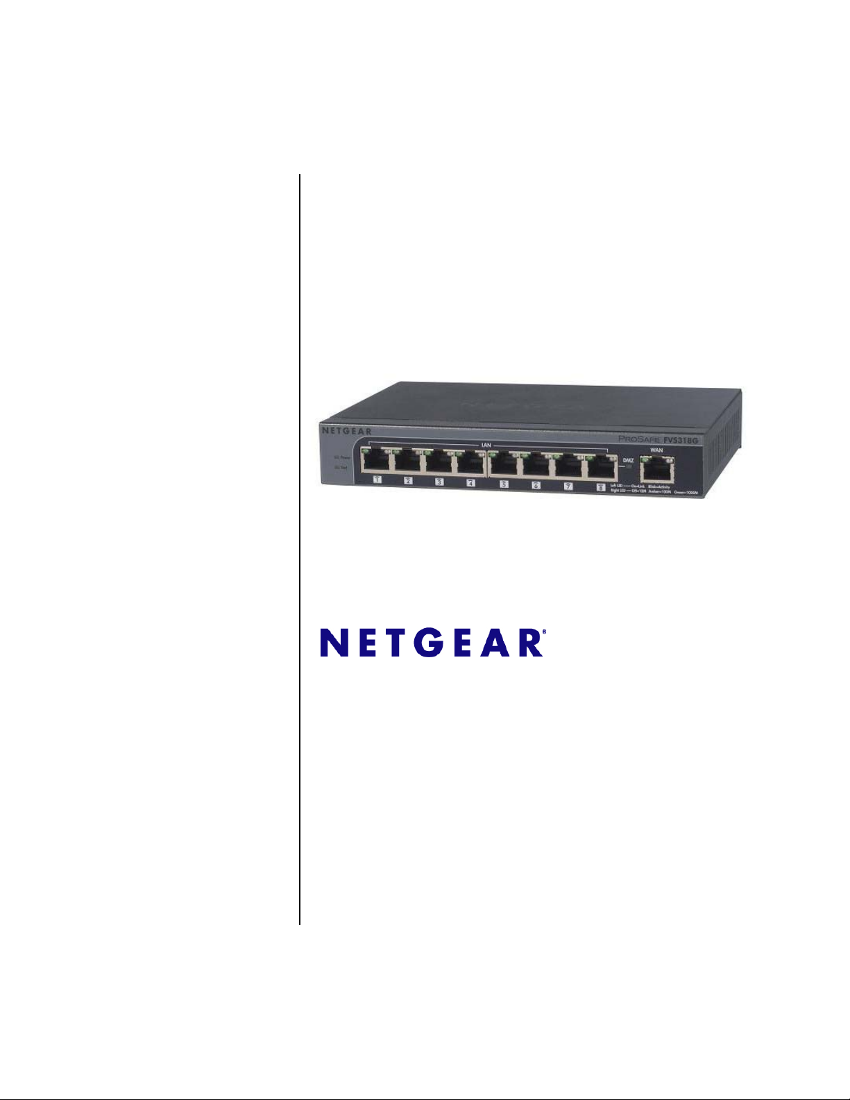
ProSafe Gigabit 8 Port
VPN Firewall FVS318G
Reference Manual
NETGEAR, Inc.
350 East Plumeria Drive
San Jose, CA 95134
202-10521-02
v1.1
August 2010
Page 2

© 2009–2010 by NETGEAR, Inc. All rights reserved.
Technical Support
Please refer to the support information card that shipped with your product. By registering your product at
http://www.netgear.com/register, we can provide you with faster expert technical support and timely notices of product
and software upgrades.
NETGEAR, INC. Support Information
Phone: 1-888-NETGEAR, for US & Canada only. For other countries, see your Support information card.
Email: support@netgear.com
North American NETGEAR website: http://www.netgear.com
Trademarks
NETGEAR and the NETGEAR logo are registered trademarks and ProSafe is a trademark of NETGEAR, Inc.
Microsoft, Windows, and Windows NT are registered trademarks of Microsoft Corporation. Other brand and product
names are registered trademarks or trademarks of their respective holders.
Statement of Conditions
In the interest of improving internal design, operational function, and/or reliability, NETGEAR reserves the right to
make changes to the products described in this document without notice.
NETGEAR does not assume any liability that may occur due to the use or application of the product(s) or circuit
layout(s) described herein.
Federal Communications Commission (FCC) Compliance Notice: Radio Frequency
Notice
This equipment has been tested and found to comply with the limits for a Class B digital device, pursuant to
part 15 of the FCC Rules. These limits are designed to provide reasonable protection against harmful interference in a
residential installation. This equipment generates, uses, and can radiate radio frequency energy and, if not installed and
used in accordance with the instructions, may cause harmful interference to radio communications. However, there is no
guarantee that interference will not occur in a particular installation. If this equipment does cause harmful interference to
radio or television reception, which can be determined by turning the equipment off and on, the user is encouraged to try
to correct the interference by one or more of the following measures:
• Reorient or relocate the receiving antenna.
• Increase the separation between the equipment and receiver.
• Connect the equipment into an outlet on a circuit different from that to which the receiver is connected.
• Consult the dealer or an experienced radio/TV technician for help.
EU Regulatory Compliance Statement
The ProSafe Gigabit 8 Port VPN Firewall FVS318G is compliant with the following EU Council Directives: 89/336/
EEC and LVD 73/23/EEC. Compliance is verified by testing to the following standards: EN55022 Class B, EN55024
and EN60950-1.
Visit the NETGEAR EU Declarations of Conformity website at:
http://kb.netgear.com/app/answers/detail/a_id/11621/sno/0
ii
v1.1, August 2010
Page 3

Bestätigung des Herstellers/Importeurs
Es wird hiermit bestätigt, daß das ProSafe Gigabit 8 Port VPN Firewall FVS318G gemäß der im BMPT-AmtsblVfg 243/
1991 und Vfg 46/1992 aufgeführten Bestimmungen entstört ist. Das vorschriftsmäßige Betreiben einiger Geräte (z.B.
Testsender) kann jedoch gewissen Beschränkungen unterliegen. Lesen Sie dazu bitte die Anmerkungen in der
Betriebsanleitung.
Das Bundesamt für Zulassungen in der Telekommunikation wurde davon unterrichtet, daß dieses Gerät auf den Markt
gebracht wurde und es ist berechtigt, die Serie auf die Erfüllung der Vorschriften hin zu überprüfen.
Certificate of the Manufacturer/Importer
It is hereby certified that the ProSafe Gigabit 8 Port VPN Firewall FVS318G has been suppressed in accordance with the
conditions set out in the BMPT-AmtsblVfg 243/1991 and Vfg 46/1992. The operation of some equipment (for example,
test transmitters) in accordance with the regulations may, however, be subject to certain restrictions. Please refer to the
notes in the operating instructions.
Federal Office for Telecommunications Approvals has been notified of the placing of this equipment on the market
and has been granted the right to test the series for compliance with the regulations.
Voluntary Control Council for Interference (VCCI) Statement
This equipment is in the second category (information equipment to be used in a residential area or an adjacent area
thereto) and conforms to the standards set by the Voluntary Control Council for Interference by Data Processing
Equipment and Electronic Office Machines aimed at preventing radio interference in such residential areas.
When used near a radio or TV receiver, it may become the cause of radio interference.
Read instructions for correct handling.
Additional Copyrights
AES Copyright (c) 2001, Dr. Brian Gladman, brg@gladman.uk.net, Worcester, UK.
All rights reserved.
TERMS
Redistribution and use in source and binary forms, with or without modification, are permitted
subject to the following conditions:
1. Redistributions of source code must retain the above copyright notice, this list of
conditions, and the following disclaimer.
2. Redistributions in binary form must reproduce the above copyright notice, this list of
conditions, and the following disclaimer in the documentation and/or other materials
provided with the distribution.
3. The copyright holder’s name must not be used to endorse or promote any products
derived from this software without his specific prior written permission.
This software is provided “as is” with no express or implied warranties of correctness or fitness
for purpose.
v1.1, August 2010
iii
Page 4

Open SSL Copyright (c) 1998–2000 The OpenSSL Project. All rights reserved.
Redistribution and use in source and binary forms, with or without modification, are permitted
provided that the following conditions are met:
1. Redistributions of source code must retain the above copyright notice, this list of
conditions, and the following disclaimer.
2. Redistributions in binary form must reproduce the above copyright notice, this list of
conditions, and the following disclaimer in the documentation and/or other materials
provided with the distribution.
3. All advertising materials mentioning features or use of this software must display the
following acknowledgment: “This product includes software developed by the OpenSSL
Project for use in the OpenSSL Toolkit (
4. The names “OpenSSL Toolkit” and “OpenSSL Project” must not be used to endorse or
promote products derived from this software without prior written permission. For written
permission, contact openssl-core@openssl.org.
5. Products derived from this software may not be called “OpenSSL” nor may “OpenSSL”
appear in their names without prior written permission of the OpenSSL Project.
6. Redistributions of any form whatsoever must retain the following acknowledgment: “This
product includes software developed by the OpenSSL Project for use in the OpenSSL
Toolkit (
THIS SOFTWARE IS PROVIDED BY THE OpenSSL PROJECT “AS IS,” AND ANY
EXPRESSED OR IMPLIED WARRANTIES, INCLUDING, BUT NOT LIMITED TO, THE
IMPLIED WARRANTIES OF MERCHANTABILITY AND FITNESS FOR A PARTICULAR
PURPOSE ARE DISCLAIMED. IN NO EVENT SHALL THE OpenSSL PROJECT OR ITS
CONTRIBUTORS BE LIABLE FOR ANY DIRECT, INDIRECT, INCIDENTAL, SPECIAL,
EXEMPLARY, OR CONSEQUENTIAL DAMAGES (INCLUDING, BUT NOT LIMITED TO,
PROCUREMENT OF SUBSTITUTE GOODS OR SERVICES; LOSS OF USE, DATA, OR
PROFITS; OR BUSINESS INTERRUPTION) HOWEVER CAUSED AND ON ANY THEORY
OF LIABILITY, WHETHER IN CONTRACT, STRICT LIABILITY, OR TORT (INCLUDING
NEGLIGENCE OR OTHERWISE) ARISING IN ANY WAY OUT OF THE USE OF THIS
SOFTWARE, EVEN IF ADVISED OF THE POSSIBILITY OF SUCH DAMAGE.
This product includes cryptographic software written by Eric Young (eay@cryptsoft.com). This
product includes software written by Tim Hudson (tjh@cryptsoft.com).
MD5 Copyright (C) 1990, RSA Data Security, Inc. All rights reserved.
License to copy and use this software is granted provided that it is identified as the “RSA Data
Security, Inc. MD5 Message-Digest Algorithm” in all material mentioning or referencing this
software or this function. License is also granted to make and use derivative works provided
that such works are identified as “derived from the RSA Data Security, Inc. MD5 MessageDigest Algorithm” in all material mentioning or referencing the derived work.
RSA Data Security, Inc. makes no representations concerning either the merchantability of
this software or the suitability of this software for any particular purpose. It is provided “as is”
without express or implied warranty of any kind.
These notices must be retained in any copies of any part of this documentation and/or
software.
http://www.openssl.org/).”
http://www.openssl.org/).”
iv
v1.1, August 2010
Page 5

PPP Copyright (c) 1989 Carnegie Mellon University. All rights reserved.
Redistribution and use in source and binary forms are permitted provided that the above
copyright notice and this paragraph are duplicated in all such forms and that any
documentation, advertising materials, and other materials related to such distribution and use
acknowledge that the software was developed by Carnegie Mellon University. The name of
the University may not be used to endorse or promote products derived from this software
without specific prior written permission.
THIS SOFTWARE IS PROVIDED “AS IS” AND WITHOUT ANY EXPRESS OR IMPLIED
WARRANTIES, INCLUDING, WITHOUT LIMITATION, THE IMPLIED WARRANTIES OF
MERCHANTIBILITY AND FITNESS FOR A PARTICULAR PURPOSE.
Zlib zlib.h. Interface of the zlib general purpose compression library version 1.1.4, March 11th,
2002. Copyright (C) 1995–2002 Jean-loup Gailly and Mark Adler.
This software is provided “as is,” without any express or implied warranty. In no event will the
authors be held liable for any damages arising from the use of this software. Permission is
granted to anyone to use this software for any purpose, including commercial applications,
and to alter it and redistribute it freely, subject to the following restrictions:
1. The origin of this software must not be misrepresented; you must not claim that you wrote
the original software. If you use this software in a product, an acknowledgment in the
product documentation would be appreciated but is not required.
2. Altered source versions must be plainly marked as such, and must not be misrepresented
as being the original software.
3. This notice may not be removed or altered from any source distribution.
Jean-loup Gailly: jloup@gzip.org; Mark Adler: madler@alumni.caltech.edu.
The data format used by the zlib library is described by RFCs (Request for Comments) 1950
to 1952 in the files
format), and rfc1952.txt (gzip format).
ftp://ds.internic.net/rfc/rfc1950.txt (zlib format), rfc1951.txt (deflate
Product and Publication Details
Model Number: FVS318G
Publication Date: August 2010
Product Family: VPN Firewall
Product Name: ProSafe Gigabit 8 Port VPN Firewall FVS318G
Home or Business Product: Business
Language: English
Publication Part Number: 202-10521-02
Publication Version Number 1.1
v1.1, August 2010
v
Page 6

vi
v1.1, August 2010
Page 7

Contents
ProSafe Gigabit 8 Port VPN Firewall FVS318G Reference Manual
About This Manual
Conventions, Formats and Scope ...................................................................................xiii
How to Print This Manual ............................................................................................... xiv
Chapter 1
Introduction
Key Features ..................................................................................................................1-1
Advanced VPN Support for IPsec ............................................................................1-2
A Powerful, True Firewall with Content Filtering ......................................................1-2
Security Features .....................................................................................................1-3
Autosensing Ethernet Connections with Auto Uplink ...............................................1-3
Extensive Protocol Support ......................................................................................1-4
Easy Installation and Management ..........................................................................1-4
Maintenance and Support ........................................................................................1-5
Package Contents ..........................................................................................................1-5
VPN Firewall Front and Rear Panels ..............................................................................1-6
Default IP Address, Login Name, and Password ...........................................................1-8
Qualified Web Browsers .................................................................................................1-8
Chapter 2
Connecting the VPN Firewall to the Internet
Understanding the Connection Steps .............................................................................2-1
Logging into the VPN Firewall ........................................................................................2-2
Navigating the Menus .....................................................................................................2-3
Configuring the Internet Connection to Your ISP ...........................................................2-4
Manually Configuring Your Internet Connection ......................................................2-6
Configuring the WAN Mode ............................................................................................2-9
Configuring Dynamic DNS ............................................................................................2-11
Configuring the Advanced Broadband Options ............................................................2-13
Additional WAN Related Configuration ..................................................................2-14
v1.1, August 2010
vii
Page 8

ProSafe Gigabit 8 Port VPN Firewall FVS318G Reference Manual
Chapter 3
LAN Configuration
Choosing the VPN Firewall DHCP Options ....................................................................3-1
Configuring the LAN Setup Options ...............................................................................3-2
Managing Groups and Hosts (LAN Groups) ...................................................................3-5
Creating the Network Database ...............................................................................3-6
Viewing the Network Database ................................................................................3-7
Adding Devices to the Network Database ................................................................3-8
Changing Group Names in the LAN Groups Database ...........................................3-9
Setting Up DHCP Address Reservation ...................................................................3-9
Configuring Multi Home LAN IP Addresses ..................................................................3-10
Configuring and Enabling the DMZ Port .......................................................................3-11
Configuring Static Routes .............................................................................................3-14
Static Route Example .............................................................................................3-16
Configuring Routing Information Protocol (RIP) ...........................................................3-17
Chapter 4
Firewall Protection and Content Filtering
About Firewall Protection and Content Filtering .............................................................4-1
Using Rules to Block or Allow Specific Kinds of Traffic ..................................................4-2
Services-Based Rules ..............................................................................................4-3
Viewing Rules and Order of Precedence for Rules ..................................................4-8
Configuring LAN WAN Rules ...................................................................................4-9
Configuring DMZ WAN Rules ................................................................................4-12
Configuring LAN DMZ Rules ..................................................................................4-13
Inbound Rules Examples .......................................................................................4-15
Outbound Rules Example ......................................................................................4-19
Configuring Other Firewall Features .............................................................................4-19
Attack Checks ........................................................................................................4-20
Setting Session Limits ............................................................................................4-22
Managing the Application Level Gateway for SIP Sessions ..................................4-23
Creating Services, QoS Profiles, and Bandwidth Profiles ............................................4-24
Adding Customized Services .................................................................................4-24
Specifying Quality of Service (QoS) Priorities ........................................................4-26
Creating Bandwidth Profiles ...................................................................................4-27
Setting a Schedule to Block or Allow Specific Traffic ...................................................4-29
viii Contents
v1.1, August 2010
Page 9

ProSafe Gigabit 8 Port VPN Firewall FVS318G Reference Manual
Blocking Internet Sites (Content Filtering) ....................................................................4-30
Configuring Source MAC Filtering ................................................................................4-33
Configuring IP/MAC Address Binding ...........................................................................4-35
Configuring Port Triggering ..........................................................................................4-37
Configuring UPnP (Universal Plug and Play) ...............................................................4-40
Email Notifications of Event Logs and Alerts ................................................................4-41
Administrator Tips .........................................................................................................4-42
Chapter 5
Virtual Private Networking
Using the VPN Wizard for Client and Gateway Configurations ......................................5-1
Creating Gateway to Gateway VPN Tunnels with the Wizard .................................5-2
Creating a Client to Gateway VPN Tunnel ...............................................................5-5
Testing the Connections and Viewing Status Information ............................................5-11
NETGEAR VPN Client Status and Log Information ...............................................5-11
VPN Firewall VPN Connection Status and Logs ....................................................5-14
Managing VPN Policies ................................................................................................5-15
Configuring IKE Policies .........................................................................................5-15
Configuring VPN Policies .......................................................................................5-23
Managing Certificates ...................................................................................................5-30
Understanding the Certificates Screen ..................................................................5-32
Viewing and Loading CA Certificates .....................................................................5-32
Understanding and Viewing Active Self Certificates ..............................................5-33
Obtaining a Self Certificate from a Certificate Authority .........................................5-35
Managing your Certificate Revocation List (CRL) ..................................................5-38
Configuring Extended Authentication (XAUTH) ............................................................5-39
Configuring XAUTH for VPN Clients ......................................................................5-39
Configuring the User Database for XAUTH ...........................................................5-41
Configuring RADIUS Clients for XAUTH ................................................................5-42
Assigning IP Addresses to Remote Users (ModeConfig) .............................................5-44
Mode Config Operation ..........................................................................................5-44
Configuring Mode Config Operation on the VPN Firewall ......................................5-45
Configuring the ProSafe VPN Client for ModeConfig .............................................5-50
Configuring Keepalives and Dead Peer Detection .......................................................5-53
Configuring Keepalives ..........................................................................................5-53
Configuring Dead Peer Detection ..........................................................................5-54
Contents ix
v1.1, August 2010
Page 10

ProSafe Gigabit 8 Port VPN Firewall FVS318G Reference Manual
Configuring NetBIOS Bridging with VPN ......................................................................5-55
Chapter 6
VPN Firewall and Network Management
Performance Management .............................................................................................6-1
Bandwidth Capacity .................................................................................................6-1
VPN Firewall Features That Reduce Traffic .............................................................6-2
VPN Firewall Features That Increase Traffic ...........................................................6-4
Using QoS to Shift the Traffic Mix ............................................................................6-7
Tools for Traffic Management ..................................................................................6-8
Configuring Users, Administrative Settings, and Remote Management .........................6-8
Changing Passwords and Settings ..........................................................................6-8
Adding External Users ...........................................................................................6-10
Configuring an External Server for Authentication .................................................6-11
Enabling Remote Management Access .................................................................6-14
Using an SNMP Manager ......................................................................................6-16
Managing the Configuration File ............................................................................6-18
Configuring Date and Time Service .......................................................................6-21
Monitoring System Performance ..................................................................................6-23
Activating Notification of Events and Alerts ............................................................6-23
Viewing the Logs ....................................................................................................6-26
Enabling the Traffic Meter ......................................................................................6-27
Viewing the VPN Firewall Configuration and System Status .................................6-30
Monitoring VPN Firewall Statistics .........................................................................6-31
Monitoring Broadband Port Status .........................................................................6-32
Monitoring Attached Devices .................................................................................6-33
Monitoring VPN Tunnel Connection Status ............................................................6-34
Viewing the VPN Logs ...........................................................................................6-35
Viewing the DHCP Log ..........................................................................................6-36
Viewing Port Triggering Status ...............................................................................6-36
Chapter 7
Troubleshooting
Basic Functions ..............................................................................................................7-1
Power LED Not On ...................................................................................................7-2
LEDs Never Turn Off ................................................................................................7-2
LAN or Internet Port LEDs Not On ...........................................................................7-2
x Contents
v1.1, August 2010
Page 11

ProSafe Gigabit 8 Port VPN Firewall FVS318G Reference Manual
Troubleshooting the Web Configuration Interface ..........................................................7-3
Troubleshooting the ISP Connection ..............................................................................7-4
Troubleshooting a TCP/IP Network Using a Ping Utility .................................................7-5
Testing the LAN Path to Your VPN Firewall .............................................................7-5
Testing the Path from Your PC to a Remote Device ................................................7-6
Restoring the Default Configuration and Password ........................................................7-7
Problems with Date and Time ........................................................................................7-7
Using the Diagnostics Utilities ........................................................................................7-8
Appendix A
Default Settings and Technical Specifications
Appendix B
Two Factor Authentication
Why do I need Two-Factor Authentication? .................................................................. B-1
What are the benefits of Two-Factor Authentication? ............................................. B-1
What is Two-Factor Authentication ......................................................................... B-2
NETGEAR Two-Factor Authentication Solutions .......................................................... B-2
Appendix C
Related Documents
Index
Contents xi
v1.1, August 2010
Page 12

ProSafe Gigabit 8 Port VPN Firewall FVS318G Reference Manual
xii Contents
v1.1, August 2010
Page 13
About This Manual
The NETGEAR® ProSafe Gigabit 8 Port VPN Firewall FVS318G Reference Manual describes
how to install, configure and troubleshoot the ProSafe Gigabit 8 Port VPN Firewall FVS318G.
The information in this manual is intended for readers with intermediate computer and Internet
skills.
Conventions, Formats and Scope
The conventions, formats, and scope of this manual are described in the following paragraphs.
• Typographical Conventions. This manual uses the following typographical conventions:
Italics Emphasis, books, CDs, file and server names, extensions
Bold User input, IP addresses, GUI screen text
Fixed Command prompt, CLI text, code
italics URL links
• Formats. This manual uses the following formats to highlight special messages:
Note: This format is used to highlight information of importance or special interest.
Tip: This format is used to highlight a procedure that will save time or resources.
Warning: Ignoring this type of note may result in a malfunction or damage to the
equipment.
Danger: This is a safety warning. Failure to take heed of this notice may result in
personal injury or death.
v1.1, August 2010
xiii
Page 14
ProSafe Gigabit 8 Port VPN Firewall FVS318G Reference Manual
• Scope. This manual is written for the VPN firewall according to these specifications.
Product Version ProSafe Gigabit 8 Port VPN Firewall FVS318G
Manual Publication Date August 2010
For more information about network, Internet, firewall, and VPN technologies, see the links to the
NETGEAR website in Appendix C, “Related Documents.”
Note: Product updates are available on the NETGEAR, Inc. website at
http://kb.netgear.com/app/home.
How to Print This Manual
To print this manual, your computer must have the free Adobe Acrobat reader installed in order to
view and print PDF files. The Acrobat reader is available on the Adobe website at
http://www.adobe.com.
Tip: If your printer supports printing two pages on a single sheet of paper, you can save
paper and printer ink by selecting this feature.
Revision History
Part Number
202-10521-01 1.0 July 2009 Product update: New firmware and new user Interface
202-10521-01 1.1 November
xiv About This Manual
Version
Number
Date Description
Update to LAN and firewall configuration
2009
v1.1, August 2010
Page 15

ProSafe Gigabit 8 Port VPN Firewall FVS318G Reference Manual
202-10521-02 1.0 April 2010 Added the following new features for the April 2010 firmware
maintenance release:
• Connection reset and delay options on the Broadband ISP
Settings screen (see “Manually Configuring Your Internet
Connection”).
• Support for an address range for inbound LAN rules on the Add
LAN WAN Inbound Service screen (see “Inbound Rules (Port
Forwarding)” and “Inbound Rules Examples”).
• Support for new log options such as Resolved DNS Names and
VPN on the Firewall Logs & E-mail screen (see “Activating
Notification of Events and Alerts”).
In addition, made the following substantial changes to the book:
• Provided new screen captures for better viewing.
• Made minor corrections throughout the manual.
• Removed the “Managing Users, Authentication, and Certificates”
chapter and included the material in other chapters.
• Made the following change to Chapter 2, “Connecting the VPN
Firewall to the Internet”:
* Updated the Broadband ISP Settings screen (Figure 2-2) and
the ISP Type options in the
Connection” section.
• Made the following changes and addition to Chapter 3, “LAN
Configuration”:
* Updated the LAN Setup screen (Figure 3-1), added LDAP
information and the Enable ARP Broadcast paragraph to the
“Configuring the LAN Setup Options” section, and revised this
section for more clarity.
* Updated the LAN Multi-homing screen (Figure 3-4) and revised
the “Configuring Multi Home LAN IP Addresses” section for more
clarity.
* Added the “Configuring and Enabling the DMZ Port” section.
• Reorganized Chapter 4, “Firewall Protection and Content
Filtering” and added the following sections to this chapter:
* “Configuring DMZ WAN Rules”
* “Configuring LAN DMZ Rules”
* “Managing the Application Level Gateway for SIP Sessions”
* “Configuring UPnP (Universal Plug and Play)”
• Made the following changes to Chapter 5, “Virtual Private
Networking”:
* Revised the “Managing VPN Policies” section
* Revised the “Managing Certificates” section
• Added the following section to Chapter 6, “VPN Firewall and
Network Management”:
* “Monitoring System Performance”
202-10521-02 1.1 Aug 2010 Added Multicast pass through to Attack Check screen.
”“Manually Configuring Your Internet
About This Manual xv
v1.1, August 2010
Page 16

ProSafe Gigabit 8 Port VPN Firewall FVS318G Reference Manual
xvi About This Manual
v1.1, August 2010
Page 17

Chapter 1
Introduction
The ProSafe Gigabit 8 Port VPN Firewall FVS318G with eight 10/100/1000 Mbps Gigabit
Ethernet LAN ports and one 10/100/1000 Mbps Gigabit Ethernet WAN port connects your local
area network (LAN) to the Internet through an external access device such as a cable modem or
DSL modem.
The FVS318G is a complete security solution that protects your network from attacks and
intrusions. For example, the FVX538 provides support for Stateful Packet Inspection, Denial of
Service (DoS) attack protection and multi-NAT support. The VPN firewall supports multiple Web
content filtering options, plus browsing activity reporting and instant alerts—both via email.
Network administrators can establish restricted access policies based on time-of-day, website
addresses and address keywords.
The FVS318G is a plug-and-play device that can be installed and configured within minutes.
This chapter contains the following sections:
• “Key Features” on this page
• “Package Contents” on page 1-5
• “VPN Firewall Front and Rear Panels” on page 1-6
• “Default IP Address, Login Name, and Password” on page 1-8
• “Qualified Web Browsers” on page 1-8
Key Features
The FVS318G provides the following features:
• One 10/100/1000 Mbps Ethernet WAN port for connection to a WAN device, such as a cable
modem or DSL modem.
• Built-in eight-port 10/100/1000 Mbps Gigabit Ethernet LAN switch for extremely fast data
transfer between local network resources.
• Support for up to 253 internal LAN users.
• Advanced VPN support for IPsec.
1-1
v1.1, August 2010
Page 18

ProSafe Gigabit 8 Port VPN Firewall FVS318G Reference Manual
• SNMP Manageable, optimized for the NETGEAR ProSafe Network Management Software
(NMS100).
• Easy, Web-based setup for installation and management.
• Advanced SPI Firewall and Multi-NAT support.
• Extensive Protocol Support.
• Login capability.
• One console port for local management.
• Front panel LEDs for easy monitoring of status and activity.
• Flash memory for firmware upgrade.
Advanced VPN Support for IPsec
The VPN firewall supports IPsec virtual private network (VPN) connections.
IPsec VPN delivers full network access between a central office and branch offices, or between a
central office and telecommuters. Remote access by telecommuters requires the installation of
VPN client software on the remote computer.
• IPsec VPN with broad protocol support for secure connection to other IPsec gateways and
clients.
• Bundled with a single-user license of the NETGEAR ProSafe VPN Client software (VPN01L)
• Supports 5 concurrent IPsec VPN tunnels.
A Powerful, True Firewall with Content Filtering
Unlike simple Internet sharing NAT routers, the FVS318G is a true firewall, using stateful packet
inspection to defend against hacker attacks. Its firewall features include:
• DoS protection. Automatically detects and thwarts DoS attacks such as Ping of Death, SYN
Flood, LAND Attack, and IP Spoofing.
• Secure Firewall. Blocks unwanted traffic from the Internet to your LAN.
• Block Sites. Blocks access from your LAN to Internet locations or services that you specify as
off-limits.
• Logs security incidents. The FVS318G will log security events such as blocked incoming
traffic, port scans, attacks, and administrator logins. You can configure the VPN firewall to
email the log to you at specified intervals. You can also configure the VPN firewall to send
immediate alert messages to your email address or email pager whenever a significant event
occurs.
1-2 Introduction
v1.1, August 2010
Page 19

ProSafe Gigabit 8 Port VPN Firewall FVS318G Reference Manual
• Keyword Filtering. With its URL keyword filtering feature, the FVS318G prevents
objectionable content from reaching your PCs. The VPN firewall allows you to control access
to Internet content by screening for keywords within Web addresses. You can configure the
VPN firewall to log and report attempts to access objectionable Internet sites.
Security Features
The FVS318G is equipped with several features designed to maintain security, as described in this
section.
• PCs Hidden by NAT. NAT opens a temporary path to the Internet for requests originating
from the local network. Requests originating from outside the LAN are discarded, preventing
users outside the LAN from finding and directly accessing the PCs on the LAN.
• Port Forwarding with NAT. Although NAT prevents Internet locations from directly
accessing the PCs on the LAN, the VPN firewall allows you to direct incoming traffic to
specific PCs based on the service port number of the incoming request. You can specify
forwarding of single ports or ranges of ports.
• DMZ port. Incoming traffic from the Internet is normally discarded by the VPN firewall
unless the traffic is a response to one of your local computers or a service for which you have
configured an inbound rule. Instead of discarding this traffic, you can have it forwarded to one
computer on your network.
Autosensing Ethernet Connections with Auto Uplink
With its internal 8-port 10/100/1000 Mbps switch and 10/100/1000 WAN port, the FVS318G can
connect to either a 10 Mbps standard Ethernet network, a 100 Mbps Fast Ethernet network, or a
1000 Mbps Gigabit Ethernet network. The LAN and WAN interfaces are autosensing and capable
of full-duplex or half-duplex operation.
The VPN firewall incorporates Auto Uplink
sense whether the Ethernet cable plugged into the port should have a ‘normal’ connection such as
to a PC or an “uplink” connection such as to a switch or hub. That port will then configure itself to
the correct configuration. This feature also eliminates the need to worry about crossover cables, as
Auto Uplink will accommodate either type of cable to make the right connection.
Introduction 1-3
TM
technology. Each Ethernet port will automatically
v1.1, August 2010
Page 20

ProSafe Gigabit 8 Port VPN Firewall FVS318G Reference Manual
Extensive Protocol Support
The FVS318G supports the Transmission Control Protocol/Internet Protocol (TCP/IP) and
Routing Information Protoco
Networking Basics” document that you can access from the link in “Related Documents” in
Appendix C.
• IP Address Sharing by NAT. The VPN firewall allows several networked PCs to share an
Internet account using only a single IP address, which may be statically or dynamically
assigned by your Internet service provider (ISP). This technique, known as NAT, allows the
use of an inexpensive single-user ISP account.
• Automatic Configuration of Attached PCs by DHCP. The VPN firewall dynamically
assigns network configuration information, including IP, gateway, and domain name server
(DNS) addresses, to attached PCs on the LAN using the Dynamic Host Configuration Protocol
(DHCP). This feature greatly simplifies configuration of PCs on your local network.
• DNS Proxy. When DHCP is enabled and no DNS addresses are specified, the VPN firewall
provides its own address as a DNS server to the attached PCs. The VPN firewall obtains actual
DNS addresses from the ISP during connection setup and forwards DNS requests from the
LAN.
• PPP over Ethernet (PPPoE). PPPoE is a protocol for connecting remote hosts to the Internet
over a DSL connection by simulating a dial-up connection. This feature eliminates the need to
run a login program such as EnterNet or WinPOET on your PC.
l (RIP). For further information about TCP/IP, see the “TCP/IP
• Quality of Service (QoS). QoS support for traffic prioritization.
Easy Installation and Management
You can install, configure, and operate the FVS318G within minutes after connecting it to the
network. The following features simplify installation and management tasks:
• Browser-Based Management. Browser-based configuration allows you to easily configure
your VPN firewall from almost any type of personal computer, such as Windows, Macintosh,
or Linux. A user-friendly Setup Wizard is provided and online help documentation is built into
the browser-based Web Management Interface.
• Auto Detect. The VPN firewall automatically senses the type of Internet connection, asking
you only for the information required for your type of ISP account.
• VPN Wizard. The VPN firewall includes the NETGEAR VPN Wizard to easily configure
VPN tunnels according to the recommendations of the Virtual Private Network Consortium
(VPNC) to ensure the VPN tunnels are interoperable with other VPNC-compliant VPN routers
and clients.
1-4 Introduction
v1.1, August 2010
Page 21

ProSafe Gigabit 8 Port VPN Firewall FVS318G Reference Manual
• SNMP. The VPN firewall supports the Simple Network Management Protocol (SNMP) to let
you monitor and manage log resources from an SNMP-compliant system manager. The SNMP
system configuration lets you change the system variables for MIB2.
• Diagnostic Functions. The VPN firewall incorporates built-in diagnostic functions such as
Ping, Trace Route, DNS lookup, and remote reboot.
• Remote Management. The VPN firewall allows you to login to the Web Management
Interface from a remote location on the Internet. For security, you can limit remote
management access to a specified remote IP address or range of addresses.
• Visual monitoring. The VPN firewall’s front panel LEDs provide an easy way to monitor its
status and activity.
Maintenance and Support
NETGEAR offers the following features to help you maximize your use of the FVS318G:
• Flash memory for firmware upgrade
• Technical support seven days a week, 24 hours a day, according to the terms identified in the
Warranty and Support information card provided with your product.
Package Contents
• The product package should contain the following items:
• FVS318G ProSafe Gigabit 8 Port VPN Firewall FVS318G
• AC power cable
• Rubber feet
• Category 5 (Cat5) Ethernet cable
• ProSafe Gigabit 8 Port VPN Firewall FVS318G Installation Guide
• Resource CD, including:
• Application Notes and other helpful information.
• ProSafe VPN Client software (one user license)
• Warranty and Support Information Card
If any of the parts are incorrect, missing, or damaged, contact your NETGEAR dealer. Keep the
carton, including the original packing materials, in case you need to return the VPN firewall for
repair.
Introduction 1-5
v1.1, August 2010
Page 22
ProSafe Gigabit 8 Port VPN Firewall FVS318G Reference Manual
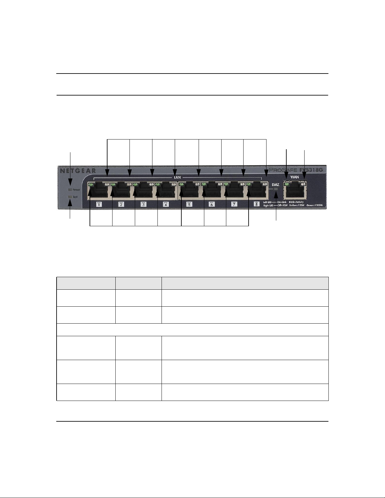
VPN Firewall Front and Rear Panels
The FVS318G front panel includes eight LAN ports, one WAN port, and four groups of status
indicator light-emitting diodes (LEDs), including Power and Test, LAN, and WAN LEDs.
4
7
1
1
6
2
3
Figure 1-1
Table 1-1 describes each item on the front panel and its operation.
Table 1-1. LED Descriptions
Object Activity Description
1. Power
2. Test
Eight LAN Ports
3. Link and Activity
(left side of port)
4. Speed
(right side of port)
5. DMZ
On (Green)
Off
On (Amber)
Off
On (Green)
Blinking (Green)
Off
On (Green)
On (Amber)
Off
On (Green)
Off
Power is supplied to the VPN firewall.
Power is not supplied to the VPN firewall.
Test mode: The system is initializing or the initialization has failed.
The system has booted successfully.
The port has detected a link with a connected Ethernet device.
Data is being transmitted or received by the port.
The port has no link.
The LAN port is operating at 1,000 Mbps.
The LAN port is operating at 100 Mbps.
The LAN port is operating at 10 Mbps.
LAN port 8 is enabled as a DMZ port.
LAN port 8 is not enabled as a DMZ port.
5
1-6 Introduction
v1.1, August 2010
Page 23
ProSafe Gigabit 8 Port VPN Firewall FVS318G Reference Manual
Table 1-1. LED Descriptions (continued)
Object Activity Description
One WAN Port
6. Active
(left side of port)
7. Speed
(right side of port)
On (Green)
Off)
On (Green)
On (Amber)
Off
The WAN port is connected.
The Internet connection is down The WAN port is either not
enabled or has no link.
The port is operating at 1,000 Mbps.
The port is operating at 100 Mbps.
The port is operating at 10 Mbps.
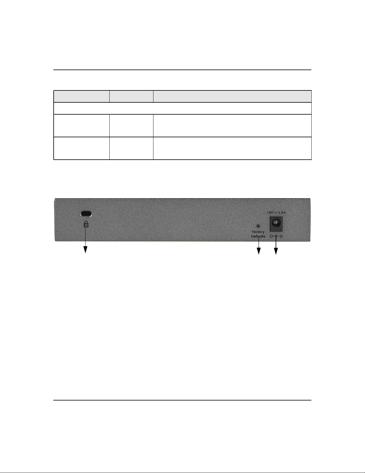
The rear panel of the FVS318G includes a cable lock receptacle, a Factory Defaults button, and a
DC power connection.
3
1
2
Figure 1-2
Viewed from left to right, the rear panel contains the following elements:
1. Cable security lock receptacle.
2. Factory Defaults button: Using a sharp object, press and hold this button for about ten seconds
until the front panel TEST light flashes to reset the VPN firewall to factory default settings.
All configuration settings will be lost and the default password will be restored.
3. DC power receptacle: 12V @ 1.5A.
Introduction 1-7
v1.1, August 2010
Page 24
ProSafe Gigabit 8 Port VPN Firewall FVS318G Reference Manual
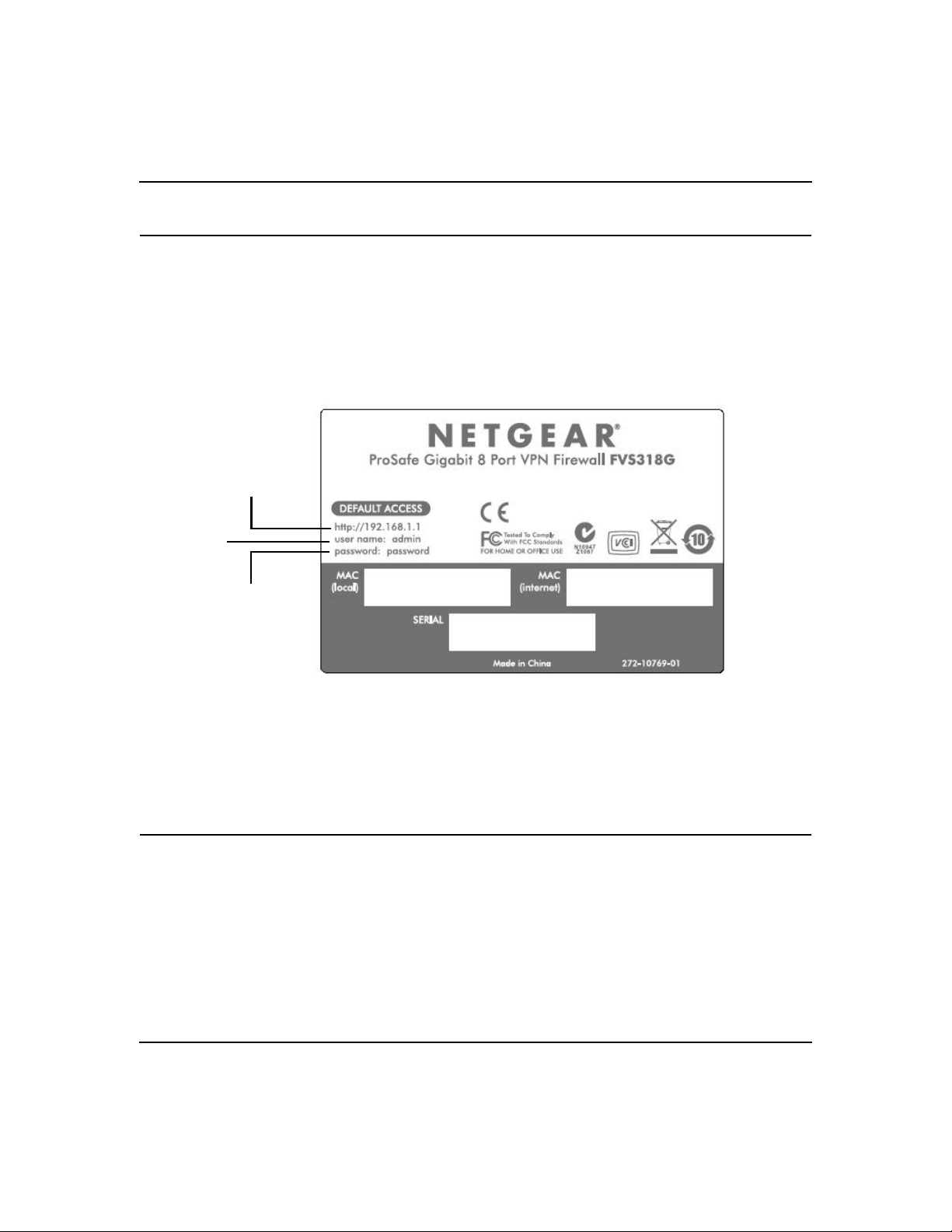
Default IP Address, Login Name, and Password
Check the label on the bottom of the FVS318G’s enclosure if you forget the following factory
default information:
• IP Address: http://192.168.1.1
• User name: admin
• Password: password
LAN IP Address
User Name
Password
Figure 1-3
When FVS318G is connected, log in by going to go to http://192.168.1.1. When the login screen
displays (see Figure 2-1 on page 2-2), enter admin for the user name and the password for
password.
Qualified Web Browsers
To configure the FVS318G, you must use a Web browser such as Internet Explorer 5.1 or higher,
Apple Safari 1.2 or higher, or Mozilla Firefox l.x Web browser with JavaScript, and cookies
enabled.
1-8 Introduction
v1.1, August 2010
Page 25

Chapter 2
Connecting the VPN Firewall to the Internet
This section provides instructions for connecting the ProSafe Gigabit 8 Port VPN Firewall
FVS318G, including these topics:
• “Understanding the Connection Steps” on this page
• “Logging into the VPN Firewall” on page 2-2
• “Navigating the Menus” on page 2-3
• “Configuring the Internet Connection to Your ISP” on page 2-4
• “Configuring the WAN Mode” on page 2-9
• “Configuring Dynamic DNS” on page 2-11
• “Configuring the Advanced Broadband Options” on page 2-13
Setting up VPN tunnels is covered in Chapter 5, “Virtual Private Networking.”
Understanding the Connection Steps
Typically, six steps are required to complete the basic Internet connection of your VPN firewall.
1. Connect the VPN firewall physically to your network. Connect the cables and restart your
network according to the instructions in the installation guide. See the ProSafe Gigabit 8 Port
VPN Firewall FVS318G Installation Guide for complete steps. A PDF of the Installation
Guide is on the NETGEAR website at: http://kbserver.netgear.com.
2. Log in to the VPN Firewall. After logging in, you are ready to set up and configure your
VPN firewall. You can also change your password and enable remote management at this
time. See “Logging into the VPN Firewall” on page 2-2.
3. Configure the Internet connection to your ISP. During this phase, you will connect to your
ISP. See “Configuring the Internet Connection to Your ISP” on page 2-4.
4. Configure the WAN mode. Select either NAT or classical routing. See “Configuring the
WAN Mode” on page 2-9.
5. Configure dynamic DNS on the WAN port (optional). As an option, configure your fully
qualified domain names during this phase. See “Configuring Dynamic DNS” on page 2-11.
2-1
v1.1, August 2010
Page 26
ProSafe Gigabit 8 Port VPN Firewall FVS318G Reference Manual
6. Configure the WAN options (optional). As an option, change the VPN firewall’s Media
Access Control (MAC) address, the factory default MTU size, and the port speed. However,
these are advanced features and changing them is not usually required. See “Configuring the
Advanced Broadband Options” on page 2-13.
Each of these tasks is detailed separately in this chapter. The configuration of firewall and VPN
features is described in later chapters.
Note: In this manual, “WAN port” and “broadband port” both indicate the same port
through which the VPN firewall connects to the Internet.
Logging into the VPN Firewall
To connect to the VPN firewall, your computer needs to be configured to obtain an IP address
automatically via DHCP. If you need instructions on how to configure you computer for DHCP,
refer to the “Preparing Your Network” document that you can access from the link in Appendix C,
“Related Documents.”
To log in to the VPN firewall:
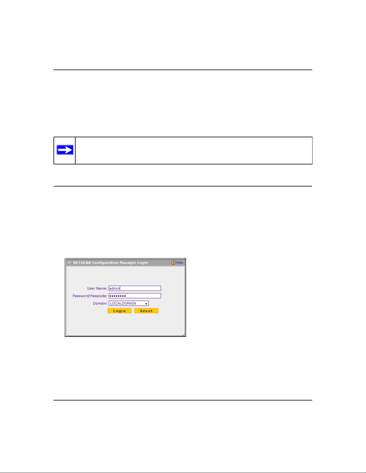
1. Connect to the VPN firewall by typing http://192.168.1.1 in the address field of your browser.
Figure 2-1
2. When prompted, enter admin for the VPN firewall user name and password for the VPN
firewall password, both in lower case letters. (The VPN firewall user name and password are
not the same as any user name or password you may use to log in to your Internet connection.)
2-2 Connecting the VPN Firewall to the Internet
v1.1, August 2010
Page 27
ProSafe Gigabit 8 Port VPN Firewall FVS318G Reference Manual
3. Click Login. The Router Status screen displays. For more information about this screen, see
“Viewing the VPN Firewall Configuration and System Status” on page 6-30.
Note: You might want to enable remote management at this time so that you can log
in remotely in the future to manage the VPN firewall (see “Configuring an
External Server for Authentication” on page 6-11). If you enable remote
management, NETGEAR strongly advises you to change your password (see
“Changing Passwords and Settings” on page 6-8).
Navigating the Menus
The Web Configuration Manager menus are organized in a layered structure of main categories
and submenus:
• Main menu. The horizontal orange bar near the top of the page is the main menu, containing
the primary configuration categories. Clicking on a primary category changes the contents of
the submenu bar.
• Submenu. The horizontal grey bar immediately below the main menu is the submenu,
containing subcategories of the currently selected primary category.
• Tab. Immediately below the submenu bar, at the top of the menu active window, are one or
more tabs, further subdividing the currently selected subcategory if necessary.
• Option arrow. To the right of the tabs on some menus are one or more blue dots with an arrow
in the center. Clicking an option arrow brings up either a popup window or an advanced option
menu.
Tip: In the instructions in this manual, we may refer to a menu using the notation
primary | subcategory, such as Network Configuration | WAN Settings. In this
example, Network is the selected primary category (in the main menu) and
WAN Settings is the selected subcategory (in the submenu).
You can now proceed to the first configuration task, configuring the VPN firewall’s Internet
connection.
Connecting the VPN Firewall to the Internet 2-3
v1.1, August 2010
Page 28
ProSafe Gigabit 8 Port VPN Firewall FVS318G Reference Manual
Configuring the Internet Connection to Your ISP
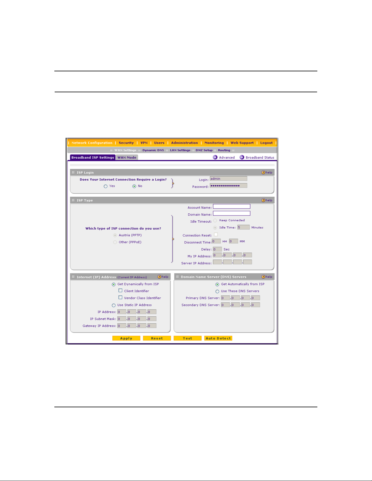
To automatically configure the broadband port and connect to the Internet:
1. Select Network Configuration from the main menu and Broadband ISP Settings from the
submenu. The Broadband ISP Settings screen displays.
Figure 2-2
2. Click Auto Detect at the bottom of the screen to automatically detect the type of Internet
connection provided by your ISP. Auto Detect will probe for different connection methods and
suggest one that your ISP will most likely support.
2-4 Connecting the VPN Firewall to the Internet
v1.1, August 2010
Page 29
ProSafe Gigabit 8 Port VPN Firewall FVS318G Reference Manual
When Auto Detect successfully detects an active Internet service, it reports which connection
type it discovered. The options are described in Table 2-1.
Note: When you click Auto Detect while the WAN port already has a connection,
you might lose the connection because the VPN firewall will enter its
detection mode.
Table 2-1. Internet connection methods
Connection
Method
PPPoE Login (Username, Password); Account Name, Domain Name
PPTP Login (Username, Password), Account Name, Local IP address, and PPTP
DHCP (Dynamic IP) No data is required.
Fixed (Static) IP Static IP address, Subnet, and Gateway IP; and related data supplied by your
Data Required
Server IP address;
ISP.
If Auto Detect does not find a connection, you will be prompted to check the physical
connection between your VPN firewall and the cable or DSL line or to check your VPN
firewall’s MAC address (see “Manually Configuring Your Internet Connection” on page 2-6).
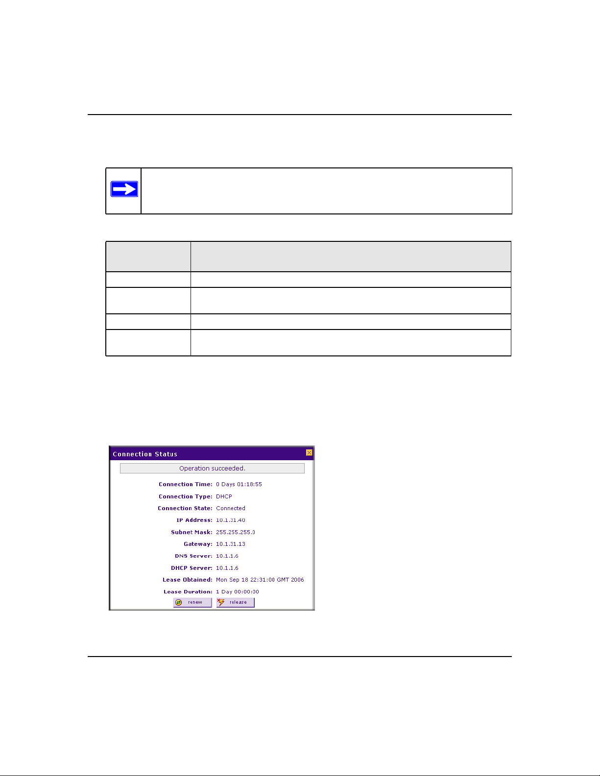
3. Click the Broadband Status option arrow at the top right of the screen to verify the WAN port
connection status. Click Connect if there is no connection.
Figure 2-3
Connecting the VPN Firewall to the Internet 2-5
v1.1, August 2010
Page 30
ProSafe Gigabit 8 Port VPN Firewall FVS318G Reference Manual
The Connection Status window should show a valid IP address and gateway. If the
configuration was not successful, skip ahead to “Manually Configuring Your Internet
Connection following this section, or see “Troubleshooting the ISP Connection” on page 7-4.
Note: If the configuration process was successful, you are connected to the Internet
through the WAN port.
If your WAN ISP configuration was successful, you can skip ahead to “Manually Configuring
Your Internet Connection” on page 2-6.
Manually Configuring Your Internet Connection
If you know your ISP connection type, you can bypass the Auto Detect feature and connect your
VPN firewall manually. Ensure that you have all of the relevant connection information such as IP
addresses, account information, type of ISP connection, and so on, before you begin. Unless your
ISP automatically assigns your configuration automatically via DHCP, you will need these
configuration settings from your ISP.
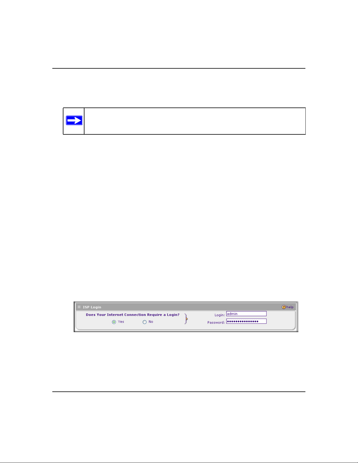
To manually configure your broadband ISP settings:
1. Select Network Configuration from the main menu and Broadband ISP Settings from the
submenu. The Broadband ISP Settings screen displays (see Figure 2-2 on page 2-4 for the
entire screen).
2. In the ISP Login section, choose one of these options:
• If your ISP requires an initial login to establish an Internet connection, click Yes (this is
the default).
• If a login is not required, click No and ignore the Login and Password fields.
Figure 2-4
3. If you clicked Yes, enter the ISP-provided Login and Password information.
2-6 Connecting the VPN Firewall to the Internet
v1.1, August 2010
Page 31

ProSafe Gigabit 8 Port VPN Firewall FVS318G Reference Manual
4. In the ISP Type section, select the type of ISP connection you use from the two listed options.
(By default, “Other (PPPoE)” is selected.)
Figure 2-5
• Other (PPPoE). If you have installed login software such as WinPoET or Ethernet, then
your connection type is PPPoE. Configure the following fields:
– Account Name. Valid account name for the PPPoE connection.
– Domain Name. Name of your ISP’s domain or your domain name if your ISP has
assigned one. In most cases, you may leave this field blank.
– Idle Timeout. Select Keep Connected, to keep the connection always on. To logout
after the connection is idle for a period of time, click Idle Time and in the timeout
field enter the number of minutes to wait before disconnecting.
– Connection Reset. Select this checkbox to to specify a time when the PPPoE WAN
connection is reset, that is, the connection is disconnected momentarily and then reestablished. Enter the hour and minutes in the Disconnect Time fields to specify when
the connection should be disconnected. Enter the seconds in the Delay field to specify
the period after which the connection should be re-established.
• PPTP. Select this option if your ISP is Austria Telecom or any other ISP that uses PPTP as
a login protocol. Configure the following fields:
– Account Name. (Also known as Host Name or System Name.) Enter the valid
account name for the PPTP connection (usually your email name as assigned by your
ISP). Some ISPs require entering your full email address here.
– Domain Name. Your domain name or workgroup name assigned by your ISP, or your
ISPs domain name. You may leave this field blank.
Connecting the VPN Firewall to the Internet 2-7
v1.1, August 2010
Page 32

ProSafe Gigabit 8 Port VPN Firewall FVS318G Reference Manual
– Idle Timeout. Check the Keep Connected radio box to keep the connection always
on. To logout after the connection is idle for a period of time, click Idle Time and
enter the number of minutes to wait before disconnecting in the timeout field. This is
useful if your ISP charges you based on the amount of time you have logged in.
– My IP Address. IP address assigned by the ISP to make the connection with the ISP
server.
– Server IP Address. IP address of the PPTP server.
5. Review the Internet (IP) Address options.
Figure 2-6
• Get Dynamically from ISP. If your ISP has not assigned a static IP address, select this
radio button. The ISP will automatically assign an IP address to the VPN firewall using
DHCP network protocol. The IP address and subnet mask fields will be inactivated. As an
option, you can select the following checkboxes:
– Client Identifier. Select this checkbox if your ISP requires the Client Identifier
information to assign an IP address using DHCP.
– Vendor Class Identifier. Select this checkbox if your ISP requires the Vendor Class
Identifier information to assign an IP address using DHCP.
• Use Static IP Address. If your ISP has assigned a fixed (static) IP address, select this
radio button, and configure the following fields:
– IP Address. Enter the Static IP address assigned to you, that identifies the VPN
firewall to your ISP.
– Subnet Mask. Enter the mask provided by the ISP or your network administrator.
– Gateway IP Address. Enter the IP address of the ISP’s gateway, provided by the ISP
or your network administrator.
2-8 Connecting the VPN Firewall to the Internet
v1.1, August 2010
Page 33

ProSafe Gigabit 8 Port VPN Firewall FVS318G Reference Manual
6. Review the Domain Name Server (DNS) server options.
Figure 2-7
• If your ISP has not assigned any Domain Name Servers (DNS) addresses, click Get
Dynamically from ISP.
• If your ISP (or your IT department) has assigned DNS addresses, click Use These DNS
Servers and enter the DNS server IP addresses provided to you in the fields.
7. Click Apply to save any changes to the broadband settings. (Or click Reset to discard any
changes and revert to the previous settings.)
8. Click Test to evaluate your entries. The VPN firewall will attempt to connect to the
NETGEAR website. If a successful connection is made, NETGEAR’s website appears.
Configuring the WAN Mode
To access the WAN Mode screen, select Network Configuration from the main menu and WAN
Settings from the submenu. The WAN Mode screen displays.
Figure 2-8
Connecting the VPN Firewall to the Internet 2-9
v1.1, August 2010
Page 34

ProSafe Gigabit 8 Port VPN Firewall FVS318G Reference Manual
The WAN Mode screen allows you to configure how the VPN firewalll uses the external Internet
connection. This screen gives you two choices for accessing the external Internet connection.
• Network Address Translation (NAT). This technique allows several computers on a LAN to
share the same Internet connection (IP address) while using private IP address on the LAN,
which are hidden from the Internet.
• Classical Routing. This method allows the VPN firewall to perform the routing, but requires
separate valid static Internet IP address for each PC on your LAN.
Network Address Translation
Network Address Translation (NAT) allows all PCs on your LAN to share a single public Internet
IP address. From the Internet, there is only a single device (the VPN firewall) and a single IP
address. PCs on your LAN can use any private IP address range, and these IP addresses are not
visible from the Internet.
• The VPN firewall uses NAT to select the correct PC (on your LAN) to receive any incoming
data.
• If you only have a single public Internet IP address, you MUST use NAT. (the default setting).
• If your ISP has provided you with multiple public IP addresses, you can use one address as the
primary shared address for Internet access by your PCs, and you can map incoming traffic on
the other public IP addresses to specific PCs on your LAN. This one-to-one inbound mapping
is configured using an inbound firewall rule.
Classical Routing
In classical routing mode, the VPN firewall performs routing, but without NAT. To gain Internet
access, each PC on your LAN must have a valid static Internet IP address.
If your ISP has allocated a number of static IP addresses to you, and you have assigned one of
these addresses to each PC, you can choose classical routing. Or, you can use classical routing for
routing private IP addresses within a campus environment.
To learn the status of the WAN port, you can view the Router Status screen (see “Viewing the
VPN Firewall Configuration and System Status” on page 6-30) or look at the LEDs on the front
panel (see “VPN Firewall Front and Rear Panels” on page 1-6).
2-10 Connecting the VPN Firewall to the Internet
v1.1, August 2010
Page 35
ProSafe Gigabit 8 Port VPN Firewall FVS318G Reference Manual
Configuring Dynamic DNS
Dynamic DNS (DDNS) is an Internet service that allows routers with varying public IP addresses
to be located using Internet domain names. To use DDNS, you must setup an account with a
DDNS provider such as DynDNS.org, TZO.com, Oray.net, or 3322.org. Links to DynDNS, TZO,
Oray, and 3322 are provided for your convenience on the Dynamic DNS Configuration screen.
The VPN firewall firmware includes software that notifies dynamic DNS servers of changes in the
WAN IP address, so that the services running on this network can be accessed by others on the
Internet.
If your network has a permanently assigned IP address, you can register a domain name and have
that name linked with your IP address by public Domain Name Servers (DNS). However, if your
Internet account uses a dynamically assigned IP address, you will not know in advance what your
IP address will be, and the address can change frequently—hence, the need for a commercial
DDNS service, which allows you to register an extension to its domain, and restores DNS requests
for the resulting FQDN to your frequently-changing IP address.
After you have configured your account information on the VPN firewall, whenever your
ISP-assigned IP address changes, your VPN firewall will automatically contact your DDNS
service provider, log in to your account, and register your new IP address.
Note: If your ISP assigns a private WAN IP address such as 192.168.x.x or 10.x.x.x, the
dynamic DNS service will not work because private addresses will not be routed
on the Internet.
To configure Dynamic DNS:
1. Select Network Configuration from the main menu and Dynamic DNS from the submenu.
The Dynamic DNS screen displays (see Figure 2-9 on page 2-12).
Connecting the VPN Firewall to the Internet 2-11
v1.1, August 2010
Page 36

ProSafe Gigabit 8 Port VPN Firewall FVS318G Reference Manual
Figure 2-9
2. Click the tab of the DNS service you want to enable. Each DNS service provider requires
registration. After registration you can configure the required settings on the corresponding
screen for the DNS service.
3. Access the website of one of the DNS service providers and set up an account. A link to each
DNS service provider is located to the right of the tabs (see the option arrow). After setting up
your account, return to the screen for the DNS service.
4. On the screen for the DNS service, select the Yes radio button, and complete the required
fields for the DNS service that you selected:
a. In the Host and Domain Name field, enter the entire FQDN name that your DNS service
provider gave you (for example: <yourname>.dyndns.org).
b. Enter the account information for the service you have chosen (for example, user name,
password, key, or domain).
c. If your DNS service provider allows the use of wild cards in resolving your URL, you may
check the Use wildcards checkbox to activate this feature.
For example, the wildcard feature will cause
the same IP address as
yourhost.dyndns.org
*.yourhost.dyndns.org to be aliased to
d. If your WAN IP address does not change often, you may need to force a periodic update to
the DDNS service to prevent your account from expiring. If it appears, you can select the
Update every 30 days checkbox to enable a periodic update.
5. Click Apply to save your configuration or click Reset to return to the previous settings.
2-12 Connecting the VPN Firewall to the Internet
v1.1, August 2010
Page 37

ProSafe Gigabit 8 Port VPN Firewall FVS318G Reference Manual
Configuring the Advanced Broadband Options
To configure the advanced broadband options:
1. Select Network Configuration from the main menu and Broadband ISP Settings from the
submenu. The Broadband ISP Settings screen displays.
2. Click the Advanced option arrow at the right of the tabs to display the Broadband Advanced
Options screen.
Figure 2-10
3. Edit the default information you want to change.
• MTU Size. The normal MTU (Maximum Transmit Unit) value for most Ethernet
networks is 1500 Bytes, or 1492 Bytes for PPPoE connections. For some ISPs you may
have to reduce the MTU. But this is rarely required, and should not be done unless you are
sure it is necessary for your ISP connection.
• Port Speed. In most cases, your VPN firewall can automatically determine the connection
speed of the Internet (WAN) port. If you cannot establish an Internet connection and the
Internet LED blinks continuously, you may have to manually select the port speed.
AutoSense is the default.
If you know that the Ethernet port on your broadband modem supports 100BaseT, select
100BaseT Half_Duplex; otherwise, select 10BaseT Half_Duplex. Use the half-duplex
settings unless you are sure you need full duplex.
Connecting the VPN Firewall to the Internet 2-13
v1.1, August 2010
Page 38

ProSafe Gigabit 8 Port VPN Firewall FVS318G Reference Manual
• Router's MAC Address. Each computer or router on your network has a unique 32-bit
local Ethernet address. This is also referred to as the computer's MAC (Media Access
Control) address. The default is Use Default Address. However, if your ISP requires
MAC authentication, then select either
– Use this Computer’s MAC address to enable the VPN firewall to use the MAC
address of the computer you are now using, or
– Use This MAC Address to manually type in the MAC address that your ISP expects.
The format for the MAC address is XX:XX:XX:XX:XX:XX (numbers 0-9 and either
uppercase or lowercase letters A-F). If you select Use This MAC Address and then type
in a MAC address, your entry will be overwritten.
Additional WAN Related Configuration
• If you want the ability to manage the VPN firewalll remotely, enable remote management at
this time (see “Enabling Remote Management Access” on page 6-14). If you enable remote
management, NETGEAR strongly recommends that you change your password (see
“Changing Passwords and Settings” on page 6-8).
• At this point, you can set up the traffic meter for each WAN, if desired. See “Enabling the
Traffic Meter” on page 6-27.
2-14 Connecting the VPN Firewall to the Internet
v1.1, August 2010
Page 39

Chapter 3
LAN Configuration
This chapter describes how to configure the advanced LAN features of your ProSafe Gigabit 8
Port VPN Firewall FVS318G, including the following sections:
• “Choosing the VPN Firewall DHCP Options” on this page
• “Configuring the LAN Setup Options” on page 3-2
• “Managing Groups and Hosts (LAN Groups)” on page 3-5
• “Configuring Multi Home LAN IP Addresses” on page 3-10
• “Configuring and Enabling the DMZ Port” on page 3-11
• “Configuring Static Routes” on page 3-14
• “Configuring Routing Information Protocol (RIP)” on page 3-17
Choosing the VPN Firewall DHCP Options
By default, the VPN firewall will function as a DHCP (Dynamic Host Configuration Protocol)
server, allowing it to assign IP, DNS server, WINS Server, and default gateway addresses to all
computers connected to the VPN firewall LAN. The assigned default gateway address is the LAN
address of the VPN firewall. IP addresses will be assigned to the attached PCs from a pool of
addresses that you must specify. Each pool address is tested before it is assigned to avoid duplicate
addresses on the LAN. The DHCP options are available for both the LAN and DMZ settings.
For most applications, the default DHCP and TCP/IP settings of the VPN firewall are satisfactory.
See the link to “TCP/IP Networking Basics” in Appendix C, “Related Documents for an
explanation of DHCP and information about how to assign IP addresses for your network.
If another device on your network will be the DHCP server, or if you will manually configure the
network settings of all of your computers, clear the Enable DHCP server radio box by selecting
the Disable DHCP Server radio box. Otherwise, leave it checked.
Specify the pool of IP addresses to be assigned by setting the starting IP address and ending IP
address. These addresses should be part of the same IP address subnet as the VPN firewall’s LAN
IP address. Using the default addressing scheme, you should define a range between 192.168.1.2
and 192.168.1.100, although you may wish to save part of the range for devices with fixed
addresses.
3-1
v1.1, August 2010
Page 40

ProSafe Gigabit 8 Port VPN Firewall FVS318G Reference Manual
The VPN firewall will deliver the following settings to any LAN device that requests DHCP:
• An IP address from the range that you have defined.
• Subnet mask.
• Gateway IP address (the VPN firewall’s LAN IP address).
• Primary DNS server (the VPN firewall’s LAN IP address).
• WINS server (if you entered a WINS server address in the DHCP section of the LAN Setup
screen).
• Lease time (date obtained and duration of lease).
DHCP Relay options allow you to make the VPN firewall a DHCP relay agent. The DHCP Relay
Agent makes it possible for DHCP broadcast messages to be sent over routers that do not support
forwarding of these types of messages. The DHCP Relay Agent is therefore the routing protocol
that enables DHCP clients to obtain IP addresses from a DHCP server on a remote subnet, or
which is not located on the local subnet. If you have no configured DHCP Relay Agent, your
clients would only be able to obtain IP addresses from the DHCP server which is on the same
subnet. To enable clients to obtain IP addresses from a DHCP server on a remote subnet, you have
to configure the DHCP Relay Agent on the subnet that contains the remote clients, so that it can
relay DHCP broadcast messages to your DHCP server.
When the DNS Proxy option is enabled, the VPN firewall will act as a proxy for all DNS requests
and communicates with the ISP’s DNS servers (as configured on the Broadband ISP Settings
screen). All DHCP clients will receive the primary and/or secondary DNS IP address along with
the IP address where the DNS proxy is running, that is, the VPN firewall’s LAN IP address. When
disabled, all DHCP clients will receive the DNS IP addresses of the ISP excluding the DNS proxy
IP address.
Configuring the LAN Setup Options
The LAN Setup screen allows configuration of LAN IP services such as DHCP and allows you to
configure a secondary or “multi-home” LAN IP setup in the LAN. The default values are suitable
for most users and situations.
Note: If you enable the DNS Relay feature, you will not use the VPN firewall as a DHCP
server but rather as a DHCP relay agent for a DHCP server somewhere else on
your network.
3-2 LAN Configuration
v1.1, August 2010
Page 41

ProSafe Gigabit 8 Port VPN Firewall FVS318G Reference Manual
To configure the LAN Setup options:
1. Select Network Configuration from the main menu and LAN Settings from the submenu.
The LAN Setup screen displays.
Figure 3-1
2. In the LAN TCP/IP Setup section, configure the following settings:
• IP Address. The LAN address of your VPN firewall (factory default: 192.168.1.1).
Note: If you change the LAN IP address of the VPN firewall while connected
through the browser, you will be disconnected. You must then open a new
connection to the new IP address and log in again. For example, if you
change the default IP address 192.168.1.1 to 10.0.0.1, you must now enter
https://10.0.0.1 in your browser to reconnect to the Web Configuration
Manager.
LAN Configuration 3-3
v1.1, August 2010
Page 42

ProSafe Gigabit 8 Port VPN Firewall FVS318G Reference Manual
• IP Subnet Mask. The subnet mask specifies the network number portion of an IP address.
Your VPN firewall will automatically calculate the subnet mask based on the IP address
that you assign. Unless you are implementing subnetting, use 255.255.255.0 as the subnet
mask. (Always make sure that the LAN port IP address and DMZ port IP address are in
different subnets.)
3. In the DHCP section, select Disable DHCP Server, Enable DHCP Server, or DHCP Relay.
By default, the VPN firewall will function as a DHCP server, providing TCP/IP configuration
settings for all computers connected to the VPN firewall’s LAN. If another device on your
network will be the DHCP server, or if you will manually configure all devices, click Disable
DHCP Server. If the VPN firewall will function as a DHCP relay agent, select DHCP Relay
and enter the IP address of the DHCP relay gateway in the Relay Gateway field.
If the DHCP server is enabled, enter the following settings:
• Domain Name. (Optional) The DHCP will assign the entered domain to DHCP clients.
• Starting IP Address. Specifies the first of the contiguous addresses in the IP address pool.
Any new DHCP client joining the LAN will be assigned an IP address between this
address and the Ending IP Address. The IP address 192.168.1.2 is the default start address.
• Ending IP Address. Specifies the last of the contiguous addresses in the IP address pool.
The IP address 192.168.1.100 is the default ending address.
Note: The starting and ending DHCP addresses should be in the same subnet as
the LAN IP address of the VPN firewall (the IP address that is configured
in the LAN TCP/IP Setup section of the LAN Setup screen).
• Primary DNS Server. (Optional) If an IP address is specified, the VPN firewall will
provide this address as the primary DNS server IP address. If no address is specified, the
VPN firewall will provide its own LAN IP address as the primary DNS server IP address.
• Secondary DNS Server. (Optional) If an IP address is specified, the VPN firewall will
provide this address as the secondary DNS server IP address.
• WINS Server. (Optional) Specifies the IP address of a local Windows NetBIOS Server if
one is present in your network.
• Lease Time. This specifies the duration for which IP addresses will be leased to clients.
3-4 LAN Configuration
v1.1, August 2010
Page 43

ProSafe Gigabit 8 Port VPN Firewall FVS318G Reference Manual
If you will use a Lightweight Directory Access Protocol (LDAP) authentication server for
network-validated domain-based authentication, select Enable LDAP Information to enable
the DHCP server to provide LDAP server information. Enter the following settings:
• LDAP Server. Specifies the name or the IP address of the device that hosts the LDAP
server.
• Search Base. Specifies the distinguished name (dn) at which to start the search, specified
as a sequence of relative distinguished names (rdn), connected with commas and without
any blank spaces. For most users, the search base is a variation of the domain name. For
example, if your domain is yourcompany.com, your search base dn might be as follows:
dc=yourcompany,dc=com.
• port. Specifies the port number that the LDAP server is using. Leave this field blank for
the default port.
4. In the Advanced Settings section, configure the following settings:
• Enable DNS Proxy. If the DNS proxy is enabled (which is the default setting), the DHCP
server will provide the VPN firewall’s LAN IP address as the DNS server for address
name resolution. If this box is unchecked, the DHCP server will provide the ISP’s DNS
server IP addresses. The VPN firewall will still service DNS requests sent to its LAN IP
address unless you disable DNS Proxy in the VPN firewall settings (see “Attack Checks”
on page 4-20).
• Enable ARP Broadcast. If ARP broadcast is enabled (which is the default setting), the
Address Resolution Protocol (ARP) is broadcasted on the LAN so that IP addresses can be
mapped to physical addresses (that is, MAC addresses).
5. Click Apply to save your settings or click Reset to discard any changes and revert to the
previous configuration.
Note: Once you have completed the LAN IP setup, all outbound traffic is allowed
and all inbound traffic is discarded. To change these traffic rules, refer to
Chapter 4, “Firewall Protection and Content Filtering.”
Managing Groups and Hosts (LAN Groups)
The Known PCs and Devices table on the Groups and Hosts screen contains a list of all known
PCs and network devices, as well as hosts, that are assigned dynamic IP addresses by this VPN
firewall. Collectively, these entries make up the Network Database.
LAN Configuration 3-5
v1.1, August 2010
Page 44

ProSafe Gigabit 8 Port VPN Firewall FVS318G Reference Manual
The Network Database is updated by these methods:
• DHCP Client Requests. By default, the DHCP server in this VPN firewall is enabled, and
will accept and respond to DHCP client requests from PCs and other network devices. These
requests also generate an entry in the Network Database. Because of this, leaving the DHCP
Server feature (on the LAN screen) enabled is strongly recommended.
• Scanning the Network. The local network is scanned using standard methods such as ARP.
This will detect active devices which are not DHCP clients. However, sometimes the name of
the PC or device cannot be accurately determined, and will be shown as Unknown.
• Manual Entry. You can manually enter information about a network device.
Creating the Network Database
Some advantages of the Network Database are:
• Generally, you do not need to enter either IP address or MAC addresses. Instead, you can just
select the desired PC or device.
• No need to reserve an IP address for a PC in the DHCP Server. All IP address assignments
made by the DHCP Server will be maintained until the PC or device is removed from the
database, either by expiry (inactive for a long time) or by you.
• No need to use a fixed IP address on PCs. Because the address allocated by the DHCP Server
will never change, you do not need to assign a fixed IP address to a PC to ensure it always has
the same IP address.
• MAC level control over PCs. The Network Database uses the MAC address to identify each
PC or device. So changing a PC’s IP address does not affect any restrictions on that PC.
• Group and individual control over PCs.
– You can assign PCs to groups and apply restrictions to each group using the Firewall
Rules screen (see “Using Rules to Block or Allow Specific Kinds of Traffic” on page 4-2).
– You can also select the groups to be covered by the Block Sites feature (see “Blocking
Internet Sites (Content Filtering)” on page 4-30).
– If necessary, you can also create firewall rules to apply to a single PC (see “Configuring
Source MAC Filtering” on page 4-33). Because the MAC address is used to identify each
PC, users cannot avoid these restrictions by changing their IP address.
• A computer is identified by its MAC address—not its IP address. Hence, changing a
computer’s IP address does not affect any restrictions applied to that PC.
3-6 LAN Configuration
v1.1, August 2010
Page 45

ProSafe Gigabit 8 Port VPN Firewall FVS318G Reference Manual
Viewing the Network Database
To view the Network Database, follow these steps:
1. Select Network Configuration from the main menu and LAN Settings from the submenu.
The LAN Setup screen displays.
2. Click the LAN Groups tab. The LAN Groups screen displays.
Figure 3-2
The Known PCs and Devices table lists the entries in the Network Database. For each computer
or device, the following fields are displayed:
• Name. The name of the computer or device. Computers that do not support the NetBIOS
protocol will be listed as Unknown. In this case, the name can be edited manually for easier
management. If the computer was assigned an IP address by the DHCP server, then an asterisk
is be appended to the name.
• IP Address. The current IP address of the computer. For DHCP clients of the VPN firewall,
this IP address will not change. If a computer is assigned a static IP address, you must to
update this entry manually when the IP address of the computer changes.
• MAC Address. The MAC address of the computer’s network interface.
• Group. Each PC or device can be assigned to a single group. By default, a computer is
assigned to the first group (Group 1). To change the group assignment by selecting the Edit
button in the Action column.
• Action/Edit. Allows modification of the selected entry.
LAN Configuration 3-7
v1.1, August 2010
Page 46

ProSafe Gigabit 8 Port VPN Firewall FVS318G Reference Manual
Adding Devices to the Network Database
To add devices manually to the network database:
1. To add computers to the network database manually, make the following selections:
• Name: The name of the PC or device.
• IP Address Type. From the pull-down menu, choose how this device receives its IP
address:
– Select Fixed (Set on PC) if the IP address is statically assigned on the computer.
– Select Reserved (DHCP Client) to direct the VPN firewall to reserve the IP address
for allocation by the DHCP server (see “Setting Up DHCP Address Reservation” on
page 3-9).
Note: When assigning a reserved IP address to a client, the IP address selected
must be outside the range of addresses allocated to the DHCP server pool.
• IP Address. Enter the IP address that this computer or device is assigned. If the IP
Address Type is Reserved (DHCP Client), the VPN firewall will reserve the IP address
for the associated MAC address.
• MAC Address. Enter the MAC address of the computer’s network interface. The MAC
address format is six colon-separated pairs of hexadecimal characters (0-9 and A-F), such
as 01:23:45:67:89:AB.
• Group. From the pull-down menu, select the group to which the computer has to be
assigned. (Group 1 is the default group.)
2. Click Add to add the new entry to the network database.
3. As an optional step: To enable DHCP address reservation for the entry that you just added to
the Known PCs and Devices table, select the checkbox for the table entry, and click Save
Binding to bind the IP address to the MAC address for DHCP assignment.
3-8 LAN Configuration
v1.1, August 2010
Page 47

ProSafe Gigabit 8 Port VPN Firewall FVS318G Reference Manual
Changing Group Names in the LAN Groups Database
By default, the LAN Groups are named Group1 through Group8. You can rename these group
names to be more descriptive, such as Engineering or Marketing.
To edit the names of any of the eight available groups:
1. From the LAN Groups screen, click the Edit Group Names option arrow to the right of the
tabs. The Network Database Group Names screen appears.
Figure 3-3
2. Select the radio button next to any group name to make that name active for editing.
3. Type a new name in the field.
4. Select and edit other group names if desired.
5. Click Apply to save your settings.
Setting Up DHCP Address Reservation
When you specify a reserved IP address for a device on the LAN (based on the MAC address of
the device), that computer or device will always receive the same IP address each time it accesses
the VPN firewall’s DHCP server. Reserved IP addresses should be assigned to servers or access
points that require permanent IP settings. The Reserved IP address that you select must be outside
of the DHCP Server pool.
To reserve an IP address, manually enter the device on the LAN Groups screen, specifying
Reserved (DHCP Client), as described in “Adding Devices to the Network Database” on page 3-
8.
LAN Configuration 3-9
v1.1, August 2010
Page 48

ProSafe Gigabit 8 Port VPN Firewall FVS318G Reference Manual
Note: The reserved address will not be assigned until the next time the PC contacts the
VPN firewall's DHCP server. Reboot the PC or access its IP configuration and
force a DHCP release and renew.
Configuring Multi Home LAN IP Addresses
If you have computers on your LAN using different IP address ranges (for example, 172.16.2.0 or
10.0.0.0), you can add “aliases” to the LAN port, giving computers on those networks access to the
Internet through the VPN firewall. This allows the VPN firewall to act as a gateway to additional
logical subnets on your LAN. You can assign the VPN firewall an IP address on each additional
logical subnet.
To add a secondary LAN IP address:
1. Select Network Configuration from the main menu and LAN Settings from the submenu.
The LAN Setup screen displays.
2. Click the LAN Multi-homing tab. The LAN Multi-homing screen displays.
Figure 3-4
The Available Secondary LAN IPs table lists the secondary LAN IP addresses added to the
VPN firewall.
• IP Address. The IP address alias added to the LAN port of the VPN firewall. This is the
gateway for computers that need to access the Internet.
• Subnet Mask. IPv4 Subnet Mask.
• Action. The Edit button allows you to make changes to the selected entry.
3-10 LAN Configuration
v1.1, August 2010
Page 49

ProSafe Gigabit 8 Port VPN Firewall FVS318G Reference Manual
3. In the Add Secondary LAN IP Address section, enter the additional IP address and subnet
mask to be assigned to the LAN port of the VPN firewall.
4. Click Add. The secondary LAN IP address will be added to the Available Secondary LAN
IPs table.
To make changes to the Available Secondary LAN IPs table, use the following buttons:
• Select All. Selects all the entries in the Available Secondary LAN IPs table.
• Delete. Deletes selected entries from the Available Secondary LAN IPs table.
Note: Additional IP addresses cannot be configured in the DHCP server. The hosts on the
secondary subnets must be manually configured with the IP addresses, gateway IP
and DNS server IPs.
Warning: Make sure that the secondary IP addresses are different from the LAN, WAN,
DMZ, and any other subnet addresses that are attached to the VPN firewall.
Example of correct addresses:
WAN IP address: 10.0.0.1 with subnet 255.0.0.0
DMZ IP address: 192.168.10.1 with subnet 255.255.255.0
LAN IP address: 192.168.1.1 with subnet 255.255.255.0
Secondary LAN IP address: 192.168.20.1 with subnet 255.255.255.0
Configuring and Enabling the DMZ Port
The De-Militarized Zone (DMZ) is a network which, when compared to the LAN, has fewer
firewall restrictions, by default. This zone can be used to host servers (such as a Web server, FTP
server, or email server, for example) and give public access to them. The eighth LAN ports on the
VPN firewall can be dedicated as a hardware DMZ port for safely providing services to the
Internet, without compromising security on your LAN.
The DMZ port feature is also helpful when using some online games and videoconferencing
applications that are incompatible with NAT. The VPN firewall is programmed to recognize some
of these applications and to work properly with them, but there are other applications that may not
function well. In some cases, local PCs can run the application properly if those PCs are used on
the DMZ port.
A separate firewall security profile is provided for the DMZ port that is hardware independent of
the standard firewall security used for the LAN.
LAN Configuration 3-11
v1.1, August 2010
Page 50

ProSafe Gigabit 8 Port VPN Firewall FVS318G Reference Manual
The DMZ Setup screen allows you to set up the DMZ port. It permits you to enable or disable the
hardware DMZ port (LAN port 8, see “VPN Firewall Front and Rear Panels” on page 1-6) and
configure an IP address and Mask for the DMZ port.
To enable and configure the DMZ port:
1. From the main menu, select Network Configuration and then select DMZ Setup from the
submenu. The DMZ Setup screen displays.
2. In the DMZ Port Setup section, under Do you want to enable DMZ Port?, select the Yes
radio box.
3. Enter an IP address and the subnet mask for the DMZ port. Make sure that the DMZ port IP
address and LAN Port IP address are in different subnets (for example, an address outside the
LAN Address pool, such as 192.168.1.101).
Figure 3-5
3-12 LAN Configuration
v1.1, August 2010
Page 51

ProSafe Gigabit 8 Port VPN Firewall FVS318G Reference Manual
4. In the DHCP for DMZ Connected Computers section, select one of the following three
radio buttons:
• Disable DHCP Server. The DHCP server is disabled, which is the default setting. Select
this radio button if another device on your DMZ network will be the DHCP server, or if
you will manually configure all devices.
• Enable DHCP Server. The DHCP server provide a TCP/IP configuration for all
computers connected to the VPN firewall’s DMZ network. Enter the following settings:
– Domain Name. (Optional) The DHCP will assign the entered domain to DHCP
clients.
– Starting IP Address. Specifies the first of the contiguous addresses in the IP address
pool. Any new DHCP client joining the LAN will be assigned an IP address between
this address and the Ending IP Address. The IP address 192.168.1.2 is the default start
address.
– Ending IP Address. Specifies the last of the contiguous addresses in the IP address
pool. The IP address 192.168.1.100 is the default ending address.
Note: The starting and ending DHCP addresses should be in the same subnet
as the LAN IP address of the VPN firewall (the IP address that is
configured in the LAN TCP/IP Setup section of the screen).
– Primary DNS Server. (Optional) If an IP address is specified, the VPN firewall will
provide this address as the primary DNS server IP address. If no address is specified,
the VPN firewall will provide its own LAN IP address as the primary DNS server IP
address.
– Secondary DNS Server. (Optional) If an IP address is specified, the VPN firewall
will provide this address as the secondary DNS server IP address.
– WINS Server. (Optional) Specifies the IP address of a local Windows NetBIOS
Server if one is present in your network.
– Lease Time. This specifies the duration for which IP addresses will be leased to
clients.
LAN Configuration 3-13
v1.1, August 2010
Page 52

ProSafe Gigabit 8 Port VPN Firewall FVS318G Reference Manual
If you will use a Lightweight Directory Access Protocol (LDAP) authentication server for
network-validated domain-based authentication, select Enable LDAP Information to
enable the DHCP server to provide LDAP server information. Enter the following
settings:
– LDAP Server. Specifies the name or the IP address of the device that hosts the LDAP
server.
– Search Base. Specifies the distinguished name (dn) at which to start the search,
specified as a sequence of relative distinguished names (rdn), connected with commas
and without any blank spaces. For most users, the search base is a variation of the
domain name. For example, if your domain is yourcompany.com, your search base dn
might be as follows: dc=yourcompany,dc=com.
– port. Specifies the port number that the LDAP server is using. Leave this field blank
for the default port.
• DHCP Relay. Select this radio button to use the VPN firewall as a DHCP relay agent for a
DHCP server somewhere else on your network. In the Relay Gateway field, enter the IP
address of the DHCP server for which the VPN firewall serves as a relay.
5. In the DNS Proxy section, select the Enable DNS Proxy checkbox to enable the DHCP server
to provide the VPN firewall’s LAN IP address for DNS address name resolution. If this
checkbox is deselected, the DHCP server will provide the ISP’s DNS server IP addresses, but
the VPN firewall will still service DNS requests that are sent to its LAN IP address.
6. Click Apply to save your settings or click Reset to discard any changes and revert to the
previous configuration.
When you enable the DMZ server, the DMZ LED next to LAN port 8 (see “VPN Firewall Front
and Rear Panels” on page 1-6) will light up indicating that the DMZ port has been enabled.
To define the DMZ WAN Rules and LAN DMZ Rules, see “Configuring DMZ WAN Rules” on
page 4-12 and “Configuring LAN DMZ Rules” on page 4-13, respectively.
Configuring Static Routes
Static routes provide additional routing information to your VPN firewall. Under normal
circumstances, the VPN firewall has adequate routing information after it has been configured for
Internet access, and you do not need to configure additional static routes. You should configure
static routes only for unusual cases such as multiple firewalls or multiple IP subnets located on
your network.
3-14 LAN Configuration
v1.1, August 2010
Page 53

ProSafe Gigabit 8 Port VPN Firewall FVS318G Reference Manual
To add a static route:
1. Select Network Configuration from the main menu and Routing from the submenu. The
Routing screen displays.
Figure 3-6
2. Click Add. The Add Static Route screen displays.
Figure 3-7
3. Enter a route name for this static route in the Route Name field (for identification and
management).
4. Select the Active checkbox to make this route effective. A route can be added to the Static
Routes table and made inactive, if not needed. This allows routes to be used as needed without
deleting the entry and re-adding it. An inactive route is not broadcast if RIP is enabled
5. Select the Private checkbox if you want to limit access to the LAN only. The static route will
not be advertised in RIP.
LAN Configuration 3-15
v1.1, August 2010
Page 54

ProSafe Gigabit 8 Port VPN Firewall FVS318G Reference Manual
6. In the Destination IP Address field, enter the destination IP address to the host or network to
which the route leads.
7. In the IP Subnet Mask field, enter the IP subnet mask for this destination. If the destination is
a single host, enter 255.255.255.255.
8. From the Interface pull-down menu, select the physical network interface (Broadband,
DMZ, or LAN) through which this route is accessible.
9. In the Gateway IP Address field, enter the gateway IP address through which the destination
host or network can be reached. (This must be a device on the same LAN segment as the VPN
firewall).
10. In the Metric field, enter the metric priority for this route. If multiple routes to the same
destination exit, the route with the lowest metric is chosen. The value must be between 1 and
15.
11. Click Reset to discard any changes and revert to the previous settings or click Apply to save
your settings. The new static route will be added to Static Routes table.
You can edit the route’s settings by clicking Edit in the Action column adjacent to the route.
Static Route Example
For example, you may require a static route if:
• your primary Internet access is through a cable modem to an ISP, and
• you have an ISDN firewall on your home network for connecting to the company where you
are employed. This firewall’s address on your LAN is 192.168.1.100, and
• your company’s network is 134.177.0.0.
When you first configured your VPN firewall, two implicit static routes were created. A default
route was created with your ISP as the gateway, and a second static route was created to your local
network for all 192.168.1.x addresses. With this configuration, if you attempt to access a device on
the 134.177.0.0 network, your VPN firewall will forward your request to the ISP. The ISP
forwards your request to the company where you are employed, and the request will likely be
denied by the company’s firewall.
In this case you must define a static route, telling your VPN firewall that 134.177.0.0 should be
accessed through the ISDN firewall at 192.168.1.100.
In this example:
• The Destination IP Address and IP Subnet Mask fields specify that this static route applies to
all 134.177.x.x addresses.
3-16 LAN Configuration
v1.1, August 2010
Page 55

ProSafe Gigabit 8 Port VPN Firewall FVS318G Reference Manual
• The Gateway IP Address fields specifies that all traffic for these addresses should be
forwarded to the ISDN firewall at 192.168.1.100.
• A Metric value of 1 will work since the ISDN firewall is on the LAN.
• Private is selected only as a precautionary security measure in case RIP is activated.
Configuring Routing Information Protocol (RIP)
RIP (Routing Information Protocol, RFC 2453) is an Interior Gateway Protocol (IGP) that is
commonly used in internal networks (LANs). It allows a router to exchange its routing information
automatically with other routers, and allows it to dynamically adjust its routing tables and adapt to
changes in the network. RIP is disabled by default.
To configure RIP:
1. Select Network Configuration from the main menu and Routing from the submenu. The
Routing screen displays (see Figure 3-6 on page 3-15).
2. Click RIP Configuration option arrow to the right of the Routing tab. The RIP Configuration
screen displays.
Figure 3-8
LAN Configuration 3-17
v1.1, August 2010
Page 56

ProSafe Gigabit 8 Port VPN Firewall FVS318G Reference Manual
3. From the RIP Direction pull-down menu, select the direction in which the VPN firewall will
send and receives RIP packets. The choices are:
• None. The VPN firewall neither broadcasts its routing table nor does it accept any RIP
packets from other routers. This effectively disables RIP.
• Both. The VPN firewall broadcasts its routing table and also processes RIP information
received from other routers.
• Out Only. The VPN firewall broadcasts its routing table periodically but does not accept
RIP information from other routers.
• In Only. The VPN firewall accepts RIP information from other routers, but does not
broadcast its routing table.
4. From the RIP Version pull-down menu, select the version:
• Disabled. The default section disables RIP versions.
• RIP-1. A class-based routing that does not include subnet information. This is the most
commonly supported version.
• RIP-2. This includes all the functionality of RIPv1 plus it supports subnet information.
Though the data is sent in RIP-2 format for both RIP-2B and RIP-2M, the modes in which
packets are sent are different.
– RIP-2B. Sends the routing data in RIP-2 format and uses subnet broadcasting.
– RIP-2M. Sends the routing data in RIP-2 format and uses multicasting.
5. Authentication for RIP2B/2M required? If you selected RIP-2B or RIP-2M, check the Yes
radio box to enable authentication, and enter the MD-5 keys to authenticate between devices in
the First Key Parameters and Second Key Parameters sections on the screen.
6. Click Reset to discard any changes and revert to the previous settings or click Apply to save
your settings.
3-18 LAN Configuration
v1.1, August 2010
Page 57

Chapter 4
Firewall Protection and Content Filtering
This chapter describes how to use the content filtering features of the ProSafe Gigabit 8 Port VPN
Firewall FVS318G to protect your network.
This chapter includes the following sections:
• “About Firewall Protection and Content Filtering” on this page
• “Using Rules to Block or Allow Specific Kinds of Traffic” on page 4-2
• “Configuring Other Firewall Features” on page 4-19
• “Creating Services, QoS Profiles, and Bandwidth Profiles” on page 4-24
• “Setting a Schedule to Block or Allow Specific Traffic” on page 4-29
• “Blocking Internet Sites (Content Filtering)” on page 4-30
• “Configuring Source MAC Filtering” on page 4-33
• “Configuring IP/MAC Address Binding” on page 4-35
• “Configuring Port Triggering” on page 4-37
• “Configuring UPnP (Universal Plug and Play)” on page 4-40
• “Email Notifications of Event Logs and Alerts” on page 4-41
• “Administrator Tips” on page 4-42
About Firewall Protection and Content Filtering
The VPN firewall provides you with Web content filtering options, plus browsing activity
reporting and instant alerts via email. Parents and network administrators can establish restricted
access policies based on time-of-day, Web addresses and Web address keywords. You can also
block Internet access by applications and services, such as chat or games.
A firewall is a special category of router that protects one network (the “trusted” network, such as
your LAN) from another (the untrusted network, such as the Internet), while allowing
communication between the two. You can further segment keyword blocking to certain known
groups (see “Managing Groups and Hosts (LAN Groups)” on page 3-5 to set up LAN Groups).
4-1
v1.1, August 2010
Page 58

ProSafe Gigabit 8 Port VPN Firewall FVS318G Reference Manual
A firewall incorporates the functions of a NAT (Network Address Translation) router, while
adding features for dealing with a hacker intrusion or attack, and for controlling the types of traffic
that can flow between the two networks. Unlike simple Internet sharing NAT routers, a firewall
uses a process called stateful packet inspection to protect your network from attacks and
intrusions. NAT performs a very limited stateful inspection in that it considers whether the
incoming packet is in response to an outgoing request, but true Stateful Packet Inspection goes far
beyond NAT.
Using Rules to Block or Allow Specific Kinds of Traffic
This section includes the following topics:
• “Services-Based Rules” on page 4-3”
• “Viewing Rules and Order of Precedence for Rules” on page 4-8
• “Configuring LAN WAN Rules” on page 4-9
• “Configuring DMZ WAN Rules” on page 4-12
• “Configuring LAN DMZ Rules” on page 4-13
• “Inbound Rules Examples” on page 4-15
• “Outbound Rules Example” on page 4-19
Firewall rules are used to block or allow specific traffic passing through from one side to the other.
You can configure up to 600 rules on the VPN firewall. Inbound rules (WAN to LAN) restrict
access by outsiders to private resources, selectively allowing only specific outside users to access
specific resources. Outbound rules (LAN to WAN) determine what outside resources local users
can have access to.
A firewall has two default rules, one for inbound traffic and one for outbound. The default rules of
the VPN firewall are:
• Inbound. Block all access from outside except responses to requests from the LAN side.
• Outbound. Allow all access from the LAN side to the outside.
The firewall rules for blocking/allowing traffic on the VPN firewall can be applied to LAN/WAN
traffic, DMZ/WAN traffic and LAN/DMZ traffic.
4-2 Firewall Protection and Content Filtering
v1.1, August 2010
Page 59

ProSafe Gigabit 8 Port VPN Firewall FVS318G Reference Manual
Services-Based Rules
The rules to block traffic are based on the traffic’s category of service.
• Outbound Rules (service blocking). Outbound traffic is normally allowed unless the VPN
firewall is configured to disallow it.
• Inbound Rules (port forwarding). Inbound traffic is normally blocked by the VPN firewall
unless the traffic is in response to a request from the LAN side. The VPN firewall can be
configured to allow this otherwise blocked traffic.
• Customized Services. Additional services can be added to the list of services in the factory
default list. These added services can then have rules defined for them to either allow or block
that traffic (see “Adding Customized Services” on page 4-24).
• Quality of Service (QoS) priorities. Each service has its own native priority that impacts its
quality of performance and tolerance for jitter or delays. You can change the QoS priority
which will change the traffic mix through the system (see “Specifying Quality of Service
(QoS) Priorities” on page 4-26).
Outbound Rules (Service Blocking)
The VPN firewall allows you to block the use of certain Internet services by PCs on your network.
This is called service blocking or port filtering.
Note: See “Configuring Source MAC Filtering” on page 4-33 for yet another way to
block outbound traffic from selected PCs that would otherwise be allowed by the
VPN firewall.
Table 4-1. Outbound Rules
Item Description
Service Select the desired service or application to be covered by this rule. If the desired service
or application does not appear in the list, you must define it using the Services menu (see
“Adding Customized Services” on page 4-24).
Action Select the desired action for outgoing connections covered by this rule:
• BLOCK always.
• BLOCK by schedule, otherwise Allow .
• ALLOW always.
• ALLOW by schedule, otherwise Block.
Note: Any outbound traffic that is not blocked by rules you create will be allowed by the
default rule.
ALLOW rules are only useful if the traffic is already covered by a BLOCK rule. That is,
you wish to allow a subset of traffic that is currently blocked by another rule.
Firewall Protection and Content Filtering 4-3
v1.1, August 2010
Page 60

ProSafe Gigabit 8 Port VPN Firewall FVS318G Reference Manual
Table 4-1. Outbound Rules (continued)
Item Description
Select Schedule Select the desired time schedule (Schedule1, Schedule2, or Schedule3) that will be used
by this rule.
• This pull-down menu gets activated only when “BLOCK by schedule, otherwise Allow”
or “ALLOW by schedule, otherwise Block” is selected as Action.
• Use schedule screen to configure the time schedules (see “Setting a Schedule to Block
or Allow Specific Traffic” on page 4-29).
LAN Users These settings determine which computers on your network are affected by this rule.
Select the desired options:
• Any. All PCs and devices on your LAN.
• Single address. Enter the required address and the rule will be applied to that
particular PC.
• Address range. If this option is selected, you must enter the start and finish fields.
• Groups. Select the Group to which this rule will apply. Use the LAN Groups screen
(under Network Configuration) to assign PCs to Groups. See “Managing Groups and
Hosts (LAN Groups)” on page 3-5.
WAN Users These settings determine which Internet locations are covered by the rule, based on their
IP address. Select the desired option:
• Any. All Internet IP address are covered by this rule.
• Single address. Enter the required address in the start field.
• Address range. If this option is selected, you must enter the start and end fields.
DMZ Users These settings determine which DMZ computers on the DMZ network are affected by this
rule. Select the desired options.
• Any. All PCs and devices on your DMZ network.
• Single address. Enter the required address and the rule will be applied to that
particular PC on the DMZ network.
• Address range. If this option is selected, you must enter the start and finish fields of
the DMZ computers.
QoS Priority Specifies the priority of a service which, in turn, determines the quality of that service for
the traffic passing through the VPN firewall. By default, the priority shown is that of the
selected service. The user can change it accordingly. If the user does not make a
selection (leaves it as Normal-Service), then the native priority of the service will be
applied to the policy. See “Specifying Quality of Service (QoS) Priorities” on page 4-26.
Log This determines whether packets covered by this rule are logged. Select the desired
action:
• Always. Always log traffic considered by this rule, whether it matches or not. This is
useful when debugging your rules.
• Never. Never log traffic considered by this rule, whether it matches or not.
4-4 Firewall Protection and Content Filtering
v1.1, August 2010
Page 61

ProSafe Gigabit 8 Port VPN Firewall FVS318G Reference Manual
Table 4-1. Outbound Rules (continued)
Item Description
Bandwidth
Profile
NAT IP The settings that specify whether the source address of the outgoing packets on the
Bandwidth Limiting determines the way in which the data is sent to or from your host. The
purpose of bandwidth limiting is to provide a solution for limiting the outgoing or incoming
traffic, thus preventing the LAN users for consuming all the bandwidth of your Internet
connection. For more information, see See “Creating Bandwidth Profiles” on page 4-27.
Note: Bandwidth limiting does not apply to the DMZ interface.
WAN should be assigned the address of the WAN interface or the address of a different
interface. The options are:
• WAN Interface Address. All the outgoing packets on the WAN are to the address of
the assigned WAN interface.
• Single Address. All the outgoing packets on the WAN are assigned the specified IP
address, for example, a secondary WAN address that you have configured.
Inbound Rules (Port Forwarding)
Because the VPN firewall uses Network Address Translation (NAT), your network presents only
one IP address to the Internet and outside users cannot directly address any of your local
computers. However, by defining an inbound rule you can make a local server (for example, a Web
server or game server) visible and available to the Internet. The rule tells the VPN firewall to direct
inbound traffic for a particular service to one local server based on the destination port number.
This is also known as port forwarding.
Whether or not DHCP is enabled, how the PCs will access the server’s LAN address impacts the
inbound rules. For example:
• If your external IP address is assigned dynamically by your ISP (DHCP enabled), the IP
address may change periodically as the DHCP lease expires. Consider using dynamic DNS so
that external users can always find your network (see “Configuring Dynamic DNS” on page 2-
11).
• If the IP address of the local server PC is assigned by DHCP, it may change when the PC is
rebooted. To avoid this, use the Reserved IP address feature to keep the PC’s IP address
constant (see “Setting Up DHCP Address Reservation” on page 3-9).
• Local PCs must access the local server using the PCs’ local LAN address. Attempts by local
PCs to access the server using the external WAN IP address will fail.
Note: See “Configuring Port Triggering” on page 4-37 for yet another way to allow
certain types of inbound traffic that would otherwise be blocked by the VPN
firewall.
Firewall Protection and Content Filtering 4-5
v1.1, August 2010
Page 62

ProSafe Gigabit 8 Port VPN Firewall FVS318G Reference Manual
Table 4-2. Inbound Rules
Item Description
Services Select the desired service or application to be covered by this rule. If the desired service
or application does not appear in the list, you must define it using the Services screen
(see “Adding Customized Services” on page 4-24).
Action Select the desired action for packets covered by this rule:
• BLOCK always.
• BLOCK by schedule, otherwise Allow.
• ALLOW always.
• ALLOW by schedule, otherwise Block.
Note: Any inbound traffic which is not allowed by rules you create will be blocked by the
Default rule.
Select Schedule Select the desired time schedule (that is, Schedule1, Schedule2, or Schedule3) that will
be used by this rule (see “Setting a Schedule to Block or Allow Specific Traffic” on
page 4-29).
• This pull-down menu gets activated only when “BLOCK by schedule, otherwise Allow”
or “ALLOW by schedule, otherwise Block” is selected as Action.
• Use the schedule screen to configure the time schedules.
Send to LAN
Server
Send to DMZ
Server
Translate to Port
Number
WAN
Destination IP
Address
LAN Users These settings determine which computers on your network are affected by this rule.
WAN Users These settings determine which Internet locations are covered by the rule, based on their
This field appears only with NAT routing (not classical routing). This LAN address or
range of LAN addresses determines which computer or computers on your network are
hosting this service rule. (You can also translate these addresses to a port number.)
The DMZ server address determines which computer on your network is hosting this
service rule. (You can also translate this address to a port number.)
Check the “Translate to Port Number” and enter a port number if you want to assign the
LAN Server to a specific port.
This setting determines the destination IP address applicable to incoming traffic.
This is the public IP address that will map to the internal LAN server; it can either be the
address of the broadband port, another public IP address
Select the desired options:
• Any. All PCs and devices on your LAN.
• Single address. Enter the required address and the rule will be applied to that
particular PC.
• Address range. If this option is selected, you must enter the start and finish fields.
• Groups. Select the Group to which this rule will apply. Use the LAN Groups screen
(under Network Configuration) to assign PCs to Groups. See “Managing Groups and
Hosts (LAN Groups)” on page 3-5.
IP addresses. Select the desired option:
• Any. All Internet IP address are covered by this rule.
• Single address. Enter the required address in the start field.
• Address range. If this option is selected, you must enter the start and end fields.
., or an address range.
4-6 Firewall Protection and Content Filtering
v1.1, August 2010
Page 63

ProSafe Gigabit 8 Port VPN Firewall FVS318G Reference Manual
Table 4-2. Inbound Rules (continued)
Item Description
Log This determines whether packets covered by this rule are logged. Select the desired
action:
• Always. Always log traffic considered by this rule, whether it matches or not. This is
useful when debugging your rules.
• Never. Never log traffic considered by this rule, whether it matches or not.
Bandwidth
Profile
Bandwidth Limiting determines the way in which the data is sent to or from your host. The
purpose of bandwidth limiting is to provide a solution for limiting the outgoing or incoming
traffic, thus preventing the LAN users for consuming all the bandwidth of your Internet
connection. For more information, see See “Creating Bandwidth Profiles” on page 4-27.
Note: Bandwidth limiting does not apply to the DMZ interface.
Note: Some residential broadband ISP accounts do not allow you to run any server
processes (such as a Web or FTP server) from your location. Your ISP may
periodically check for servers and may suspend your account if it discovers any
active services at your location. If you are unsure, refer to the Acceptable Use
Policy of your ISP.
Remember that allowing inbound services opens holes in your VPN firewall. Only enable those
ports that are necessary for your network. It is also advisable to turn on the server application
security and invoke the user password or privilege levels, if provided.
Firewall Protection and Content Filtering 4-7
v1.1, August 2010
Page 64

ProSafe Gigabit 8 Port VPN Firewall FVS318G Reference Manual
Viewing Rules and Order of Precedence for Rules
To view the firewall rules, select Security from the main menu and Firewall from the submenu.
The LAN WAN Rules screen appears (Figure 4-1 shows some examples). As you define new
rules, they are added to the tables in the Rules menu as the last item in the list.
Figure 4-1
For LAN WAN rules, DMZ WAN rules, and LAN DMZ rules, for any traffic attempting to pass
through the VPN firewall, the packet information is subjected to the rules in the order shown in the
Outbound Services and Inbound Services rules tables rules tables, beginning at the top and
proceeding to the bottom. In some cases, the order of precedence of two or more rules may be
important in determining the disposition of a packet. For example, you should place the most strict
rules at the top (those with the most specific services or addresses). The up and down button
allows you to relocate a defined rule to a new position in the table (see below).
4-8 Firewall Protection and Content Filtering
v1.1, August 2010
Page 65

ProSafe Gigabit 8 Port VPN Firewall FVS318G Reference Manual
To make changes to an existing outbound or inbound service rule on the the LAN WAN Rules,
DMZ WAN Rules, or LAN DMZ Rules screen, in the Action column to the right of to the rule,
click on of the following table buttons:
• edit. Allows you to make any changes to the rule definition of an existing rule. Depending on
your selection, either an Edit Outbound Service screen or Edit Inbound Service screen
displays, containing the data for the selected rule.
• up. Moves the rule up one position in the table rank.
• down. Moves the rule down one position in the table rank.
To enable, disable, or delete one or more rules on the LAN WAN Rules, DMZ WAN Rules, or
LAN DMZ Rules screen:
1. Select the checkbox to the left of the rule that you want to delete or disable or click the select
all table button to select all rules.
2. Click one of the following table buttons:
• enable. Enables the rule or rules. The “!” status icon changes from a grey circle to a green
circle, indicating that the rule is or rules are enabled. (By default, when a rule is added to
the table, it is automatically enabled.)
• disable. Disables the rule or rules. The “!” status icon changes from a green circle to a
grey circle, indicating that the rule is or rules are disabled.
• delete. Deletes the rule or rules.
To add a new rule, click Add. For more information, see “Configuring LAN WAN Rules” on this
page, “Configuring DMZ WAN Rules” on page 4-12, and “Configuring LAN DMZ Rules” on
page 4-13.
Configuring LAN WAN Rules
The default outbound policy is to allow all traffic to the Internet to pass through. Firewall rules can
then be applied to block specific types of traffic from going out from the LAN to the Internet
(outbound). The default policy of Allow Always can be changed to block all outbound traffic
which then allows you to enable only specific services to pass through the VPN firewall.
To change the default outbound policy:
1. Select Security from the main menu and Firewall Rules from the submenu. The LAN WAN
Rules screen displays (see Figure 4-1 on page 4-8).
2. Change the Default Outbound Policy by selecting Block Always from the pull-down menu.
3. Click Apply.
Firewall Protection and Content Filtering 4-9
v1.1, August 2010
Page 66

ProSafe Gigabit 8 Port VPN Firewall FVS318G Reference Manual
LAN WAN Outbound Services Rules
You may define rules that will specify exceptions to the default rules. By adding custom rules, you
can block or allow access based on the service or application, source or destination IP addresses,
and time of day. The outbound rule will block the selected application from any internal IP LAN
address to any external WAN IP address according to the schedule created in the Schedule menu.
You can also tailor these rules to your specific needs (see “Administrator Tips” on page 4-42).
Note: This feature is for advanced administrators only! Incorrect configuration will cause
serious problems.
To create a new LAN WAN outbound service rule:
1. In the LAN WAN Rules screen, click Add under the Outbound Services table. The Add LAN
WAN Outbound Service screen displays...
Figure 4-2
2. Configure the settings based on the descriptions in Table 4-1 on page 4-3.
3. Click Apply to save your changes and reset the fields on this screen. The new rule will be
listed in the Outbound Services table.
4-10 Firewall Protection and Content Filtering
v1.1, August 2010
Page 67

ProSafe Gigabit 8 Port VPN Firewall FVS318G Reference Manual
LAN WAN Inbound Services Rules
This Inbound Services table lists all existing rules for inbound traffic. If you have not defined any
rules, no rules will be listed. By default, all inbound traffic is blocked. Remember that allowing
inbound services opens holes in your VPN firewall. Only enable those ports that are necessary for
your network.
To create a new LAN WAN inbound service rule:
1. In the LAN WAN Rules screen, click Add under the Inbound Services table. The Add LAN
WAN Inbound Service screen displays.
Figure 4-3
2. Configure the settings based on the descriptions in Table 4-2 on page 4-6.
3. Click Apply to save your changes and reset the fields on this screen. The new rule will be
listed in the Inbound Services table.
Firewall Protection and Content Filtering 4-11
v1.1, August 2010
Page 68

ProSafe Gigabit 8 Port VPN Firewall FVS318G Reference Manual
Configuring DMZ WAN Rules
The firewall rules for traffic between the DMZ and the WAN/Internet are configured on the DMZ
WAN Rules screen. The Default Outbound Policy is to allow all traffic from and to the Internet to
pass through. Firewall rules can then be applied to block specific types of traffic from either going
out from the DMZ to the Internet (outbound) or coming in from the Internet to the DMZ
(inbound). The default outbound policy can be changed to block all outbound traffic and enable
only specific services to pass through the VPN firewall by adding an outbound services rule.
To create a new DMZ WAN outbound service policy:
1. Select Security from the main menu and Firewall Rules from the submenu. The LAN WAN
Rules screen displays.
2. Select the DMZ WAN Rules tab. The DMZ WAN Rules screen displays.
Figure 4-4
3. Click Add under the Outbound Services table. The Add DMZ WAN Outbound Service
screen displays (see Figure 4-5 on page 4-13).
4-12 Firewall Protection and Content Filtering
v1.1, August 2010
Page 69
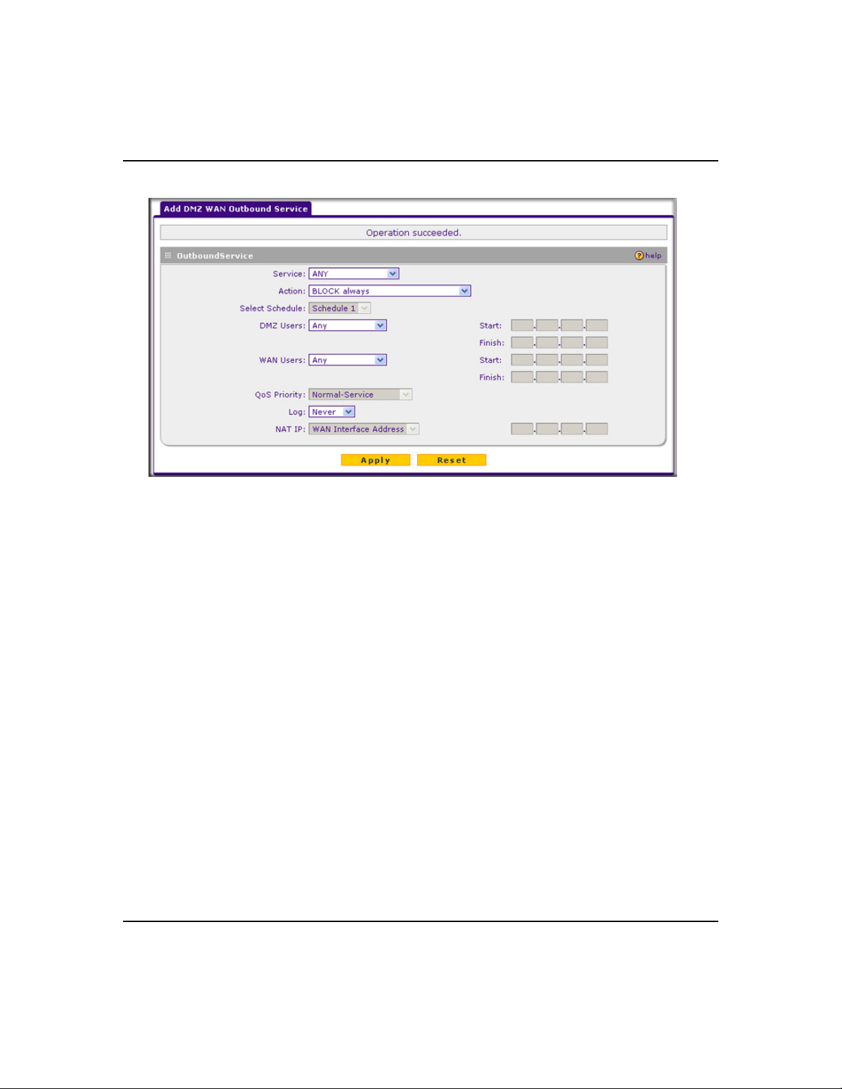
ProSafe Gigabit 8 Port VPN Firewall FVS318G Reference Manual
Figure 4-5
4. Configure the settings based on the descriptions in Table 4-1 on page 4-3.
5. Click Apply. The new rule will appear in the Outbound Services table. The rule is
automatically enabled.
The procedure to add a new DMZ WAN inbound service policy is similar to the procedure
described above with the exception that you click Add under the Inbound Services table, you
configure the settings based on the descriptions in Table 4-2 on page 4-6, and the policy is added
to the Inbound Services table.
Configuring LAN DMZ Rules
The LAN DMZ Rules screen allows you to create rules that define the movement of traffic
between the LAN and the DMZ. The Default Outbound and Inbound Policies is to allow all traffic
between the local LAN and DMZ network. Firewall rules can then be applied to block specific
types of traffic from either going out from the LAN to the DMZ (outbound) or coming in from the
DMZ to the LAN (inbound).
Firewall Protection and Content Filtering 4-13
v1.1, August 2010
Page 70

ProSafe Gigabit 8 Port VPN Firewall FVS318G Reference Manual
To create a new LAN DMZ outbound service policy:
1. Select Security from the main menu and Firewall Rules from the submenu. The LAN WAN
Rules screen displays.
2. Select the LAN DMZ Rules tab. The LAN DMZ Rules screen displays.
Figure 4-6
3. Click Add under the Outbound Services table. The Add LAN DMZ Outbound Service screen
displays.
Figure 4-7
4. Configure the settings based on the descriptions in Table 4-1 on page 4-3.
4-14 Firewall Protection and Content Filtering
v1.1, August 2010
Page 71

ProSafe Gigabit 8 Port VPN Firewall FVS318G Reference Manual
5. Click Apply. The new rule will appear in the Outbound Services table. The rule is
automatically enabled.
The procedure to add a new LAN DMZ inbound service policy is similar to the procedure
described above with the exception that you click Add under the Inbound Services table, you
configure the settings based on the descriptions in Table 4-2 on page 4-6, and the policy is added
to the Inbound Services table.
Inbound Rules Examples
LAN WAN Inbound Rule: Hosting a Local Public Web Server
If you host a public Web server on your local network, you can define a rule to allow inbound Web
(HTTP) requests from any outside IP address to the IP address of your Web server at any time of
day.
Figure 4-8
Firewall Protection and Content Filtering 4-15
v1.1, August 2010
Page 72

ProSafe Gigabit 8 Port VPN Firewall FVS318G Reference Manual
LAN WAN Inbound Rule: Allowing Videoconference from Restricted Addresses
If you want to allow incoming videoconferencing to be initiated from a restricted range of outside
IP addresses, such as from a branch office, you can create an inbound rule.
Figure 4-9
In the example, CU-SeeMe connections are allowed only from a specified range of external IP
addresses.
LAN WAN or DMZ WAN Inbound Rule: Setting Up One-to-One NAT Mapping
If you arrange with your ISP to have more than one public IP address for your use, you can use the
additional public IP addresses to map to servers on your LAN or DMZ. One of these public IP
addresses will be used as the primary IP address of the VPN firewall. This address will be used to
provide Internet access to your LAN PCs through NAT. The other addresses are available to map
to your servers.
In the example shown in Figure 4-10 on page 4-17, we have configured multi-NAT to support
multiple public IP addresses on one WAN interface. The inbound rule instructs the VPN firewall
to host an additional public IP address (10.1.0.5) and to associate this address with the Web server
on the LAN (at 192.168.1.1). We also instruct the VPN firewall to translate the incoming HTTP
port number (port 80) to a different port number (port 8080).
4-16 Firewall Protection and Content Filtering
v1.1, August 2010
Page 73

ProSafe Gigabit 8 Port VPN Firewall FVS318G Reference Manual
Figure 4-10
The following addressing scheme is used in this example:
• VPN firewall FVS318G
– WAN primary public IP address: 10.1.0.1
– WAN additional public IP address: 10.1.0.5
– LAN IP address 192.168.1.1
• Web server PC on the VPN firewall’s LAN
– LAN IP address: 192.168.1.11
– Port number for Web service: 8080
To test the connection from a PC on the WAN side, type http://10.1.0.5. The home page of the
Web server should appear.
LAN WAN or DMZ WAN Inbound Rule: Specifying an Exposed Host
Specifying an exposed host allows you to set up a computer or server that is available to anyone on
the Internet for services that you have not yet defined.
Firewall Protection and Content Filtering 4-17
v1.1, August 2010
Page 74

ProSafe Gigabit 8 Port VPN Firewall FVS318G Reference Manual
To expose one of the PCs on your LAN or DMZ as this host:
1. Create an inbound rule that allows all protocols.
2. Place the rule below all other inbound rules.
Note: For security, NETGEAR strongly recommends that you avoid creating an exposed
host. When a computer is designated as the exposed host, it loses much of the
protection of the firewall and is exposed to many exploits from the Internet. If
compromised, the computer can be used to attack your network.
1. Select Any and Allow Always (or Allow by Schedule)
2. Place rule below all other inbound rules
Figure 4-11
4-18 Firewall Protection and Content Filtering
v1.1, August 2010
Page 75

ProSafe Gigabit 8 Port VPN Firewall FVS318G Reference Manual
Outbound Rules Example
Outbound rules let you prevent users from using applications such as Instant Messenger, Real
Audio or other non-essential sites.
LAN WAN Outbound Rule: Blocking Instant Messenger
If you want to block Instant Messenger usage by employees during working hours, you can create
an outbound rule to block that application from any internal IP address to any external address
according to the schedule that you have created in the Schedule menu.
Figure 4-12
You can also have the VPN firewall log any attempt to use Instant Messenger during that blocked
period.
Configuring Other Firewall Features
You can configure attack checks, set session limits, and manage the Application Level Gateway
(ALG) for SIP sessions.
Firewall Protection and Content Filtering 4-19
v1.1, August 2010
Page 76

ProSafe Gigabit 8 Port VPN Firewall FVS318G Reference Manual
Attack Checks
The Attack Checks screen allows you to specify whether or not the VPN firewall should be
protected against common attacks in the DMZ, LAN and WAN networks. To enable the
appropriate attack checks for your environment:
1. Select Security from the main menu and Firewall Rules from the submenu. The LAN WAN
Rules screen displays.
2. Click the Attack Checks tab. The Attack Checks screen displays.
Figure 4-13
3. Check the boxes for the Attack Checks you wish to monitor. The various types of attack
checks are listed and defined below. Click Apply to save your settings.
The various types of attack checks listed on the Attack Checks screen are:
• WAN Security Checks
– Respond To Ping On Internet Ports. By default, the VPN firewall responds to an ICMP
Echo (ping) packet coming from the Internet or WAN side. Responding to a ping can be a
useful diagnostic tool when there are connectivity problems. If the ping option is enabled,
you can allow either any IP address or a specific IP address only to respond to a ping. You
can disable the ping option to prevent hackers from easily discovering the VPN firewall
via a ping.
– Enable Stealth Mode. In stealth mode, the VPN firewall will not respond to port scans
from the WAN or Internet, which makes it less susceptible to discovery and attacks.
4-20 Firewall Protection and Content Filtering
v1.1, August 2010
Page 77

ProSafe Gigabit 8 Port VPN Firewall FVS318G Reference Manual
– Block TCP Flood. A SYN flood is a form of denial of service attack in which an attacker
sends a succession of SYN requests to a target system. When the system responds, the
attacker does not complete the connection, thus saturating the server with half-open
connections. No legitimate connections can then be made.
When blocking is enabled, the VPN firewall will limit the lifetime of partial connections
and will be protected from a SYN flood attack.
• LAN Security Checks
– Block UDP flood. A UDP flood is a form of denial of service attack in which the
attacking machine sends a large number of UDP packets to random ports to the victim
host. As a result, the victim host will check for the application listening at that port, see
that no application is listening at that port, and reply with an ICMP Destination
Unreachable packet.
When the victimized system is flooded, it is forced to send many ICMP packets,
eventually making it unreachable by other clients. The attacker may also spoof the IP
address of the UDP packets, ensuring that the excessive ICMP return packets do not reach
him, making the attacker’s network location anonymous.
If flood checking is enabled, the VPN firewall will not accept more than 20 simultaneous,
active UDP connections from a single computer on the LAN.
– Disable Ping Reply on LAN Ports. To prevent the VPN firewall from responding to ping
requests from the LAN, click this checkbox.
• VPN Pass through. When the VPN firewall functions in NAT mode, all packets going to the
Remote VPN Gateway are first filtered through NAT and then encrypted per the VPN policy.
If a VPN client or gateway on the LAN side of the VPN firewall wants to connect to another
VPN endpoint on the WAN, with the VPN firewall between the two VPN end points, all
encrypted packets will be sent to the VPN firewall. Since the VPN firewall filters the
encrypted packets through NAT, the packets become invalid.
IPsec, PPTP, and L2TP represent different types of VPN tunnels that can pass through the
VPN firewall. To allow the VPN traffic to pass through without filtering, enable those options
for the type of tunnel(s) that will pass through the VPN firewall.
• Multicast Pass through. IGMP is a communications protocol used to manage IP multicast
groups. Checking this option results in IGMP Proxy being enabled for WAN (upstream) and
LAN (downstream) interfaces. If checked, the router will keep track of IGMP group
membership reports from LAN hosts joining and leaving the group. The relevant multicast
traffic will be forwarded from WAN to LAN.
Firewall Protection and Content Filtering 4-21
v1.1, August 2010
Page 78

ProSafe Gigabit 8 Port VPN Firewall FVS318G Reference Manual
Setting Session Limits
Session Limit allows you to specify the total number of sessions allowed, per user, over an IP
(Internet Protocol) connection across the VPN firewall. This feature is enabled on the Session
Limit screen and shown below in Figure 4-14. Session Limit is disabled by default.
To set session limits:
1. Select Security from the main menu and Firewall Rules from the submenu. The LAN WAN
Rules screen displays.
2. Click the Session Limit tab. The Session Limit screen displays..
Figure 4-14
3. Click the Yes radio button under Do you want to enable Session Limit?
4. From the User Limit Parameter pull-down menu, define the maximum number of sessions
per IP either as a percentage of maximum sessions or as an absolute.
The percentage is computed on the total connection capacity of the device.
5. Enter the User Limit. If the User Limit Parameter is set to Percentage of Max Sessions, this
is the maximum number of sessions allowed from a single source machine as a percentage of
the total connection capacity. (Session Limit is per machine based.) Otherwise, if the User
Limit Parameter is set to Number of Sessions, the user limit is an absolute value.
4-22 Firewall Protection and Content Filtering
v1.1, August 2010
Page 79

ProSafe Gigabit 8 Port VPN Firewall FVS318G Reference Manual
Note: Some protocols (such as FTP or RSTP) create two sessions per connection
which should be considered when configuring Session Limiting.
The Total Number of Packets Dropped due to Session Limit field shows total number of
packets dropped when session limit is reached.
6. In the Session Timeout section, modify the TCP, UDP and ICMP timeout values as you
require. A session will expire if no data for the session is received for the duration of the
timeout value. The default timeout values are 1200 seconds for TCP sessions, 180 seconds for
UDP sessions, and 8 seconds for ICMP sessions.
7. Click Apply to save your settings.
Managing the Application Level Gateway for SIP Sessions
The Application Level Gateway (ALG) facilitates multimedia sessions such as voice over IP
(VoIP) sessions that use the Session Initiation Protocol (SIP) across the firewall and provides
support for multiple SIP clients. ALG support for SIP is disabled by default.
To enable ALG for SIP:
1. Select Security from the main menu and Firewall Rules from the submenu. The LAN WAN
Rules screen displays.
2. Click the Advanced tab. The Advanced screen displays.
Figure 4-15
3. Select the Enable SIP ALG checkbox.
4. Click Apply to save your settings.
Firewall Protection and Content Filtering 4-23
v1.1, August 2010
Page 80

ProSafe Gigabit 8 Port VPN Firewall FVS318G Reference Manual
Creating Services, QoS Profiles, and Bandwidth Profiles
When you create inbound and outbound firewall rules, you use firewall objects such as services,
QoS profiles, bandwidth profiles, and schedules to narrow down the firewall rules:
• Services. A service narrows down the firewall rule to an application and a port number. For
information about adding services, see “Adding Customized Services” on page 4-24.
• QoS profiles. A quality of service (QoS) profile defines the relative priority of an IP packet
for traffic that matches the firewall rule. For information about creating QoS profiles, see
“Specifying Quality of Service (QoS) Priorities” on page 4-26.
• Bandwidth Profiles. A bandwidth profile allocates and limits traffic bandwidth for the LAN
users to which a firewall rule is applied. For information about creating bandwidth profiles,
see “Creating Bandwidth Profiles” on page 4-27.
Note: A schedule narrows down the period during which a firewall rule is applied. For
information about specifying schedules, see “Setting a Schedule to Block or Allow
Specific Traffic” on page 4-29.
Adding Customized Services
Services are functions performed by server computers at the request of client computers. You can
configure up to 125 custom services.
For example, Web servers serve Web pages, time servers serve time and date information, and
game hosts serve data about other players’ moves. When a computer on the Internet sends a
request for service to a server computer, the requested service is identified by a service or port
number. This number appears as the destination port number in the transmitted IP packets. For
example, a packet that is sent with destination port number 80 is an HTTP (Web server) request.
The service numbers for many common protocols are defined by the Internet Engineering Task
Force (IETF) and published in RFC1700, “Assigned Numbers.” Service numbers for other
applications are typically chosen from the range 1024 to 65535 by the authors of the application.
Although the VPN firewall already holds a list of many service port numbers, you are not limited
to these choices. Use the Services screen to add additional services and applications to the list for
use in defining firewall rules. The Services screen shows a list of services that you have defined, as
shown in Figure 4-16 on page 4-25.
4-24 Firewall Protection and Content Filtering
v1.1, August 2010
Page 81

ProSafe Gigabit 8 Port VPN Firewall FVS318G Reference Manual
To define a new service, first you must determine which port number or range of numbers is used
by the application. This information can usually be determined by contacting the publisher of the
application or from user groups of newsgroups. When you have the port number information, you
can enter it on the Services screen.
To add a customized service:
1. Select Security from the main menu and Services from the submenu. The Services screen
displays.
Figure 4-16
2. In the Add Custom Services section of the screen, specify a new service:
a. Enter a descriptive name for the service (this is for your convenience).
b. Select the Layer 3 Protocol that the service uses as its transport protocol. It can be TCP,
UDP or ICMP.
c. Enter the first TCP or UDP port of the range that the service uses. If the service uses only
one port, then the Start Port and the Finish Port will be the same.
d. Enter the last port of the range that the service uses. If the service only uses a single port
number, enter the same number in both fields.
3. Click Add. The new custom service will be added to the Custom Services Table.
Firewall Protection and Content Filtering 4-25
v1.1, August 2010
Page 82

ProSafe Gigabit 8 Port VPN Firewall FVS318G Reference Manual
Modifying a Service
To edit the settings of a service:
1. In the Custom Services Table, click the Edit icon adjacent to the service you want to edit.
The Edit Service screen displays.
Figure 4-17
2. Modify the settings you wish to change.
3. Click Reset to cancel the changes and restore the previous settings or click Apply to confirm
your changes. The modified service displays in the Custom Services Table.
Specifying Quality of Service (QoS) Priorities
The Quality of Service (QoS) Priorities setting determines the priority of a service, which in turn,
determines the quality of that service for the traffic passing through the firewall. The user can
change this priority
• On the Services screen in the Custom Services Table for customized services (see
Figure 4-16).
• On the Add LAN WAN Outbound Services screen (see Figure 4-2 on page 4-10).
• On the Add DMZ WAN Outbound Services screen (see Figure 4-5 on page 4-13).
The QoS priority definition for a service determines the queue that is used for the traffic passing
through the VPN firewall. A priority is assigned to IP packets using this service. Priorities are
defined by the “Type of Service (ToS) in the Internet Protocol Suite” standards, RFC 1349.
4-26 Firewall Protection and Content Filtering
v1.1, August 2010
Page 83

ProSafe Gigabit 8 Port VPN Firewall FVS318G Reference Manual
A ToS priority for traffic passing through the VPN firewall is one of the following:
• Normal-Service. No special priority given to the traffic. The IP packets for services with this
priority are marked with a ToS value of 0.
• Minimize-Cost. Used when data has to be transferred over a link that has a lower “cost”. The
IP packets for services with this priority are marked with a ToS value of 1.
• Maximize-Reliability. Used when data needs to travel to the destination over a reliable link
and with little or no retransmission. The IP packets for services with this priority are marked
with a ToS value of 2.
• Maximize-Throughput. Used when the volume of data transferred during an interval is
important even if the latency over the link is high. The IP packets for services with this priority
are marked with a ToS value of 4.
• Minimize-Delay. Used when the time required (latency) for the packet to reach the destination
must be low. The IP packets for services with this priority are marked with a ToS value of 8.
Creating Bandwidth Profiles
Bandwidth limiting determines the way in which data is communicated with your host. The
purpose of bandwidth limiting is to provide a method for limiting traffic, thus preventing LAN
users from consuming all the bandwidth on your broadband link. Bandwidth limiting does not
apply to the DMZ interface.
For example, when a new connection is established by a device, the device will locate the firewall
rule corresponding to the connection.
• If the rule has a bandwidth profile specification, then the device will create a bandwidth class
in the kernel.
• If multiple connections correspond to the same firewall rule, they will share the same class.
An exception occurs for an individual bandwidth profile if the classes are per source IP. The source
IP is the IP of the first packet of the connection:
The class is deleted when all the connections using the class expire.
Firewall Protection and Content Filtering 4-27
v1.1, August 2010
Page 84

ProSafe Gigabit 8 Port VPN Firewall FVS318G Reference Manual
To add a bandwidth profile:
1. Select Security from the main menu and Bandwidth Profile from the submenu. The
Bandwidth Profile screen displays.
Figure 4-18
2. Click Add to add a new bandwidth profile. The Add New Bandwidth Profile screen displays.
Figure 4-19
3. Enter the following information:
a. Enter a Profile Name. This name will become available in the firewall rules definition
menus.
b. From the Direction pull-down menu, select whether the profile will apply to outbound,
inbound, or both outbound and inbound traffic.
4-28 Firewall Protection and Content Filtering
v1.1, August 2010
Page 85

ProSafe Gigabit 8 Port VPN Firewall FVS318G Reference Manual
c. Depending on the direction that you selected, enter the minimum and maximum
bandwidths to be allowed:
• Enter the Outbound Minimum Bandwidth and Outbound Maximum Bandwidth
in Kbps.
• Enter the Inbound Minimum Bandwidth and Inbound Maximum Bandwidth in
Kbps.
The minimum bandwidth can range from 0 Kbps to the maximum bandwidth that you
specify. The maximum bandwidth can range from 100 Kbps to 100,000 Kbps.
d. From the Type pull-down menu, select whether the profile will apply to a group or
individual.
4. Click Apply. The new bandwidth profile will be added to the List of Bandwidth Profiles
table.
To edit a bandwidth profile:
1. Click the Edit button adjacent to the profile you want to edit. The Edit Bandwidth Profile
screen is displayed. (This screen shows the same fields as the Add New Bandwidth Profile
screen.)
2. Modify the settings that you wish to change.
3. Click Apply. Your modified profile displays in the List of Bandwidth Profiles table.
To remove an entry from the table, select the profile and click delete.
To remove all the profiles, click select All and then click delete.
Setting a Schedule to Block or Allow Specific Traffic
Schedules define the timeframes under which firewall rules may be applied.
Three schedules, Schedule 1, Schedule 2 and Schedule3 can be defined, and any one of these can
be selected when defining firewall rules.
To invoke rules based on a schedule, follow these steps:
1. Select Security from the main menu and Schedule from the submenu. The Schedule 1 screen
displays (see Figure 4-20 on page 4-30).
Firewall Protection and Content Filtering 4-29
v1.1, August 2010
Page 86

ProSafe Gigabit 8 Port VPN Firewall FVS318G Reference Manual
Figure 4-20
2. Check the radio button for All Days or Specific Days. If you chose Specific Days, check the
radio button for each day you want the schedule to be in effect.
3. Check the radio button to schedule the time of day: All Day, or Specific Times. If you chose
Specific Times, enter the Start Time and End Time fields (Hour, Minute, AM/PM), which
will limit access during certain times for the selected days.
4. Click Apply to save your settings to Schedule 1.
Repeat these steps to set to a schedule for Schedule 2 and Schedule 3.
Blocking Internet Sites (Content Filtering)
If you want to restrict internal LAN users from access to certain sites on the Internet, you can use
the VPN firewall’s Content Filtering and Web Components filtering. By default, these features are
disabled; all requested traffic from any website is allowed. If you enable one or more of these
features and users try to access a blocked site, they will see a “Blocked by NETGEAR” message.
Several types of blocking are available:
• Web Components blocking. You can block the following Web component types: Proxy, Java,
ActiveX, and Cookies. Some of these components are can be used by malicious Websites to
infect computers that access them. Even sites on the Trusted Domains list will be subject to
Web Components blocking when the blocking of a particular Web component is enabled.
4-30 Firewall Protection and Content Filtering
v1.1, August 2010
Page 87

ProSafe Gigabit 8 Port VPN Firewall FVS318G Reference Manual
– Proxy. A proxy server (or simply, proxy) allows computers to route connections to other
computers through the proxy, thus circumventing certain firewall rules. For example, if
connections to a specific IP address are blocked by a firewall rule, the requests can be
routed through a proxy that is not blocked by the rule, rendering the restriction ineffective.
Enabling this feature blocks proxy servers.
– Java. Blocks java applets from being downloaded from pages that contain them. Java
applets are small programs embedded in Web pages that enable dynamic functionality of
the page. A malicious applet can be used to compromise or infect computers. Enabling this
setting blocks Java applets from being downloaded.
– ActiveX. Similar to Java applets, ActiveX controls install on a Windows computer
running Internet Explorer. A malicious ActiveX control can be used to compromise or
infect computers. Enabling this setting blocks ActiveX applets from being downloaded.
– Cookies. Cookies are used to store session information by websites that usually require
login. However, several websites use cookies to store tracking information and browsing
habits. Enabling this option filters out cookies from being created by a website..
Note: Many websites require that cookies be accepted in order for the site to be
accessed properly. Blocking cookies may interfere with useful functions
provided by these websites.
• Keyword Blocking (Domain Name Blocking). You can specify up to 32 words that, should
they appear in the website name (URL) or in a newsgroup name, will cause that site or
newsgroup to be blocked by the VPN firewall.
You can apply the keywords to one or more groups. Requests from the PCs in the groups for
which keyword blocking has been enabled will be blocked. Blocking does not occur for the
PCs that are in the groups for which keyword blocking has not been enabled.
You can bypass keyword blocking for trusted domains by adding the exact matching domain
to the list of Trusted Domains. Access to the domains or keywords on this list by PCs, even
those in the groups for which keyword blocking has been enabled, will still be allowed without
any blocking.
Keyword application examples:
• If the keyword “XXX” is specified, the URL <http://www.badstuff.com/xxx.html> is blocked,
as is the newsgroup alt.pictures.XXX.
• If the keyword “.com” is specified, only Web sites with other domain suffixes (such as .edu or
.gov) can be viewed.
• If you wish to block all Internet browsing access, enter the keyword “.”.
Firewall Protection and Content Filtering 4-31
v1.1, August 2010
Page 88

ProSafe Gigabit 8 Port VPN Firewall FVS318G Reference Manual
To enable Content Filtering:
1. Select Security from the main menu and Block Sites from the submenu. The Block Sites
screen displays.
Figure 4-21
4-32 Firewall Protection and Content Filtering
v1.1, August 2010
Page 89

ProSafe Gigabit 8 Port VPN Firewall FVS318G Reference Manual
2. Check the Yes radio button to enable content filtering.
3. Click Apply to activate the screen controls.
4. Check the radio boxes of any Web components you wish to block.
5. Check the radio buttons of the groups to which you wish to apply keyword blocking. Click
Enable to activate keyword blocking (or disable to deactivate keyword blocking).
6. Build your list of blocked keywords or domain names in the Blocked Keyword fields. After
each entry, click Add. The keyword or domain name will be added to the Blocked Keywords
table. (You can also edit an entry by clicking Edit in the Action column adjacent to the entry.)
7. Build a list of trusted domains in the Trusted Domains fields. After each entry, click Add.
The trusted domain will appear in the Trusted Domains table. (You can also edit any entry by
clicking Edit in the Action column adjacent to the entry.)
Configuring Source MAC Filtering
Source MAC filtering allows you to filter out traffic coming from certain known machines or
devices.
• By default, the source MAC address filter is disabled. All the traffic received from PCs with
any MAC address is allowed.
• When enabled, traffic will be dropped coming from any computers or devices whose MAC
addresses are listed in MAC Addresses table.
Note: For additional ways of restricting outbound traffic, see “Outbound Rules (Service
Blocking)” on page 4-3.
To enable MAC filtering and add MAC addresses to be blocked:
1. Select Security from the main menu and Address Filter from the submenu. The Source MAC
Filter screen displays (see Figure 4-22 on page 4-34).
Firewall Protection and Content Filtering 4-33
v1.1, August 2010
Page 90

ProSafe Gigabit 8 Port VPN Firewall FVS318G Reference Manual
Figure 4-22
2. Check the Yes radio box in the MAC Filtering Enable section.
3. Select the action to be taken on outbound traffic from the listed MAC addresses:
• Block this list and permit all other MAC addresses.
• Permit this list and block all other MAC addresses.
4. Enter a MAC Address in the Add Source MAC Address checkbox and click Add. The MAC
address will appear in the MAC Addresses table. Repeat this process to add additional MAC
addresses.
A valid MAC address is six colon-separated pairs of hexadecimal digits (0 to 9 and a to f). For
example: 01:23:45:ab:cd:ef.
5. Click Reset to cancel a MAC address entry before adding it to the table or click Apply to save
your settings.
You can edit the MAC address by clicking Edit in the Action column adjacent to the MAC
Address.
To remove an entry from the table, select the MAC address entry and click Delete.
To select all the list of MAC addresses, click Select All. A checkmark will appear in the box to the
left of each MAC address in the MAC Addresses table
4-34 Firewall Protection and Content Filtering
v1.1, August 2010
.
Page 91

ProSafe Gigabit 8 Port VPN Firewall FVS318G Reference Manual
Configuring IP/MAC Address Binding
IP/MAC binding allows you to bind an IP address to a MAC address and the other way around.
Some devices are configured with static addresses. To prevent users from changing their static IP
addresses, IP/MAC binding must be enabled on the VPN firewall. If the VPN firewall detects
packets with a matching IP address, but with the inconsistent MAC address (or the other way
around), it will drop these packets. If users have enabled the logging option for IP/MAC binding,
these packets will be logged before they are dropped. The VPN firewallwill then display the total
number of dropped packets that violated either the IP-to-MAC binding or the MAC-to-IP binding.
Following is an example:
Assume that three computers on the LAN are set up as follows:
• Host1: MAC address (00:01:02:03:04:05) and IP address (192.168.10.10)
• Host2: MAC address (00:01:02:03:04:06) and IP address (192.168.10.11)
• Host3: MAC address (00:01:02:03:04:07) and IP address (192.168.10.12)
If all the above host entries are added to the IP/MAC Binding table, the following scenarios
indicate the possible outcome.
• Host1: Matching IP address and MAC address in the IP/MAC Bindings table.
• Host2: Matching IP address but inconsistent MAC address in the IP/MAC Bindings table.
• Host3: Matching MAC address but inconsistent IP address in the IP/MAC Bindings table.
The VPN firewall will block the traffic coming from Host2 and Host3, but allow the traffic coming
from Host1 to any external network. The total count of dropped packets will be displayed.
To enable IP/MAC binding and add IP and MAC addresses for binding:
1. Select Security from the main menu and Address Filter from the submenu.
2. Select the IP/MAC Binding tab. The IP/MAC Binding screen displays (see Figure 4-23 on
page 4-36).
Firewall Protection and Content Filtering 4-35
v1.1, August 2010
Page 92

ProSafe Gigabit 8 Port VPN Firewall FVS318G Reference Manual
Figure 4-23
3. Select the Yes radio box and click Apply. Make sure that you have enabled the e-maling of
logs (see “Activating Notification of Events and Alerts” on page 6-23).
4. Add an IP/MAC Bind rule by entering:
a. Name. Specify an easily identifiable name for this rule.
b. MAC Address. Specify the MAC Address for this rule.
c. IP Addresses. Specify the IP Address for this rule.
d. Log Dropped Packets. Select the logging option for this rule from the pull-down menu.
5. Click Add. The new IP/MAC binding rule will be appear the IP/MAC Bindings table.
The IP/MAC Bindings table lists the currently defined IP/MAC binding rules:
• Name. Displays the user-defined name for this rule.
• MAC Addresses. Displays the MAC Addresses for this rule.
• IP Addresses. Displays the IP Addresses for this rule.
• Log Dropped Packets. Displays the logging option for this rule.
4-36 Firewall Protection and Content Filtering
v1.1, August 2010
Page 93

ProSafe Gigabit 8 Port VPN Firewall FVS318G Reference Manual
To edit an IP/MAC binding rule, click Edit adjacent to the entry. The following fields of an
existing IP/MAC binding rule can be modified:
• MAC Address. Specify the MAC Address for this rule.
• IP Addresses. Specify the IP Address for this rule.
• Log Dropped Packets. Specify the logging option for this rule.
To remove an entry from the table, select the IP/MAC binding entry and click Delete.
To see the counter that shows the packets that were dropped because of IP-MAC binding
violations and to set the poll interval, click the Set Poll Interval option arrow at the top of the
IP/MAC Binding screen.
Configuring Port Triggering
Port triggering allows some applications to function correctly that would otherwise be partially
blocked by the VPN firewall when it functions in NAT mode. Some applications require that when
external devices connect to them, they receive data on a specific port or range of ports. The VPN
firewall must send all incoming data for that application only on the required port or range of
ports. Using this feature requires that you know the port numbers used by the application.
Port triggering allows computers on the private network (LAN) to request that one or more ports
be forwarded to them. Unlike basic port forwarding which forwards ports to only one
preconfigured IP address, port triggering waits for an outbound request from the private network
on one of the defined outgoing ports. It then automatically sets up forwarding to the IP address that
sent the request. When the application ceases to transmit data over the port, the VPN firewall waits
for a timeout interval and then closes the port or range of ports, making them available to other
computers on the private network.
Once configured, port triggering operates as follows:
1. A PC makes an outgoing connection using a port number defined in the Port Triggering table.
2. The VPN firewall records this connection, opens the additional incoming port or ports
associated with this entry in the Port Triggering table, and associates them with the PC.
3. The remote system receives the PCs request and responds using the different port numbers that
you have now opened.
4. The VPN firewall matches the response to the previous request, and forwards the response to
the PC.
Firewall Protection and Content Filtering 4-37
v1.1, August 2010
Page 94

ProSafe Gigabit 8 Port VPN Firewall FVS318G Reference Manual
Without port triggering, this response would be treated as a new connection request rather than a
response. As such, it would be handled in accordance with the port forwarding rules.
Note these restrictions with port triggering:
• Only one PC can use a port triggering application at any time.
• After a PC has finished using a port triggering application, there is a time-out period before the
application can be used by another PC. This is required because the VPN firewall cannot
detect when the application has terminated.
Note: For additional ways of allowing inbound traffic, see “Inbound Rules (Port
Forwarding)” on page 4-5.
To add a port triggering Rule:
1. Select Security from the main menu and Port Triggering from the submenu. The Port
Triggering screen displays.
Figure 4-24
2. Enter a user-defined name for this rule in the Name field.
3. From the Enable pull-down menu, indicate if the rule is enabled or disabled.
4. From the Protocol pull-down menu, select either the TCP or UDP protocol.
5. In the Outgoing (Trigger) Port Range fields:
4-38 Firewall Protection and Content Filtering
v1.1, August 2010
Page 95

ProSafe Gigabit 8 Port VPN Firewall FVS318G Reference Manual
a. Enter the Start Port range (1 - 65534).
b. Enter the End Port range (1 - 65534).
6. In the Incoming (Response) Port Range fields:
a. Enter the Start Port range (1 - 65534).
b. Enter the End Port range (1 - 65534).
7. Click Add. The Port Triggering Rule will be added to the Port Triggering table.
To edit or modify a rule:
1. Click Edit in the Action column opposite the rule you wish to edit. The Edit Port Triggering
Rule screen displays.
Figure 4-25
2. Modify any of the fields for this rule.
3. Click Reset to cancel any changes and return to the previous settings or click Apply to save
your modifications. Your changes will appear in the Port Triggering table.
Firewall Protection and Content Filtering 4-39
v1.1, August 2010
Page 96

ProSafe Gigabit 8 Port VPN Firewall FVS318G Reference Manual
To check the status of the port triggering rules, click the Status option arrow on the Port Triggering
screen.
Figure 4-26
Configuring UPnP (Universal Plug and Play)
The UPnP (Universal Plug and Play) feature allows the VPN Firewall to automatically discover
and configure the devices when it searches over LAN and WAN.
1. To access the UPnP screen, click Security > UPnP in the main/submenu. The UPnP screen is
displayed.
Figure 4-27
2. To enable the UPnP feature, click the Yes radio button. (The feature is enabled by default.) To
disable the feature, click or No.
4-40 Firewall Protection and Content Filtering
v1.1, August 2010
Page 97

ProSafe Gigabit 8 Port VPN Firewall FVS318G Reference Manual
3. Configure the following fields:
– Advertisement Period. Enter the period in minutes that specified how often the VPN
firewall should broadcast its UPnP information to all devices within its range.
– Advertisement Time to Live. Enter a number that specifies how many steps (hops) each
UPnP packet is allowed to propagate before being discarded. Small values will limit the
UPnP broadcast range.
4. Click Apply to save your settings.
The UPnP Portmap Table shows the IP addresses and other settings of UPnP devices that
have accessed the VPN firewall.
– Active. A Yes or No indicates if the UPnP device port that established a connection is
currently active.
– Protocol. Indicates the network protocol such as HTTP or FTP that is used by the device
to connect to the VPN firewall.
– Int. Port. Indicates if any internal ports are opened by the UPnP device.
– Ext. Port. Indicates if any external ports are opened by the UPnP device.
– IP Address. Lists the IP address of the UPnP device accessing the VPN firewall.
To refresh the contents of the UPnP Portmap Table, click refresh.
Email Notifications of Event Logs and Alerts
The firewall logs can be configured to log and then email denial of access, general attack
information, and other information to a specified email address. For example, your VPN firewall
will log security-related events such as: accepted and dropped packets on different segments of
your LAN; denied incoming and outgoing service requests; hacker probes and login attempts; and
other general information based on the settings that you enter on the Firewall Logs & E-mail
screen. In addition, if you have set up content filtering on the Block Sites screen (see “Blocking
Internet Sites (Content Filtering)” on page 4-30), a log will be generated when someone on your
network tries to access a blocked site.
To configure email or syslog notification, or to view the logs, see “Activating Notification of
Events and Alerts” on page 6-23.
Firewall Protection and Content Filtering 4-41
v1.1, August 2010
Page 98

ProSafe Gigabit 8 Port VPN Firewall FVS318G Reference Manual
Administrator Tips
Consider the following operational items:
• As an option, you can enable remote management if you have to manage distant sites from a
central location (see “Configuring an External Server for Authentication” on page 6-11).
• Although rules (see “Using Rules to Block or Allow Specific Kinds of Traffic” on page 4-2) is
the basic way of managing the traffic through your system, you can further refine your control
with the following optional features of the VPN firewall:
– Groups and hosts (see “Managing Groups and Hosts (LAN Groups)” on page 3-5)
– Services (see “Services-Based Rules” on page 4-3)
– Schedules (see “Setting a Schedule to Block or Allow Specific Traffic” on page 4-29)
– Block sites (see “Blocking Internet Sites (Content Filtering)” on page 4-30)
– Source MAC filtering (see “Configuring Source MAC Filtering” on page 4-33)
– Port triggering (see “Configuring Port Triggering” on page 4-37)
4-42 Firewall Protection and Content Filtering
v1.1, August 2010
Page 99

Chapter 5
Virtual Private Networking
This chapter describes how to use the virtual private networking (VPN) features of the ProSafe
Gigabit 8 Port VPN Firewall FVS318G.
This chapter includes the following sections:
• “Using the VPN Wizard for Client and Gateway Configurations” on this page
• “Testing the Connections and Viewing Status Information” on page 5-11
• “Managing VPN Policies” on page 5-15
• “Managing Certificates” on page 5-30
• “Configuring Extended Authentication (XAUTH)” on page 5-39
• “Assigning IP Addresses to Remote Users (ModeConfig)” on page 5-44
• “Configuring Keepalives and Dead Peer Detection” on page 5-53
• “Configuring NetBIOS Bridging with VPN” on page 5-55
Using the VPN Wizard for Client and Gateway Configurations
You use the VPN Wizard to configure multiple gateway or client VPN tunnel policies.
The section below provides wizard and NETGEAR VPN Client configuration procedures for the
following scenarios:
• Using the wizard to configure a VPN tunnel between two VPN gateways
• Using the wizard to configure a VPN tunnel between a VPN gateway and a VPN client
Configuring a VPN tunnel connection requires that all settings on both sides of the VPN tunnel
match or mirror each other precisely, which can be a daunting task. The VPN Wizard efficiently
guides you through the setup procedure with a series of questions that will determine the IPsec
keys and VPN policies it sets up. The VPN Wizard will also set the settings for the network
connection: Security Association, traffic selectors, authentication algorithm, and encryption. The
settings used by the VPN wizard are based on the recommendations of the VPN Consortium
(VPNC), an organization that promotes multi-vendor VPN interoperability.
5-1
v1.1, August 2010
Page 100

ProSafe Gigabit 8 Port VPN Firewall FVS318G Reference Manual
Creating Gateway to Gateway VPN Tunnels with the Wizard
Figure 5-1
Follow these steps to set up a gateway VPN tunnel using the VPN Wizard.
1. Select VPN from the main menu and VPN Wizard from the submenu. The VPN Wizard
screen displays.
Figure 5-2
5-2 Virtual Private Networking
v1.1, August 2010
 Loading...