

NETGEAR EN106TP, EN108TP, EN104TPNA Installation Manual

Start Here
Congratulations on your purchase of the NETGEAR™ Model EN104TP, Model
EN106
TP
, or M ode l EN1 08TP Ethernet hub. The hubs deliver standards-based,
plug-and-play networking soluti ons for small businesses, hom e offices, and lo wdensity workgroups of lar ger companies.
In this installation guide, all three hubs are referred to collectively as the Model
EN104TP/EN106TP/EN108
TP
hub. Each hub is listed individually when
information is provided that refers to a specific model.
Features
TP
The Model EN104
/EN106TP/EN108
• Four (on the Model EN104
eight (on the Model EN108
that provide 10 megabit per second (Mbps) networking using simple
unshielded twisted pair (UTP) wiring
• Built-in LED indicators for at-a-glance status checks provided by vista
network ports
• Uplink port for connecting to other hubs using simple straight-through
cables
• Clear front-panel light-emitting diode (LED) indicators to monitor overall
hub status
TP
hub has the following features:
TP
hub), six (on the Model EN106
TP
hub) vista 10BASE-T network ports (RJ-45)
TP
hub), and
• Plug-and-play instal lation with no software to configure
• Complete hub functions including packet retiming, collision detection,
preamble regeneration, and fragment extensi on
• Automatic partitioning and reconnection of a port that has excessive
collisions or is jabbering
• Automatic polarity detection for recognizing and correcting incorrect
polarity on the receive pair
• Compact design, enabling easy tabletop or rack-mounting installa tion
• External power adapter
• Limited five-year warranty on the unit and one-year warranty on the power
supply
Model EN104TP/EN106TP/EN108TP Ethernet Hub Installation Guide
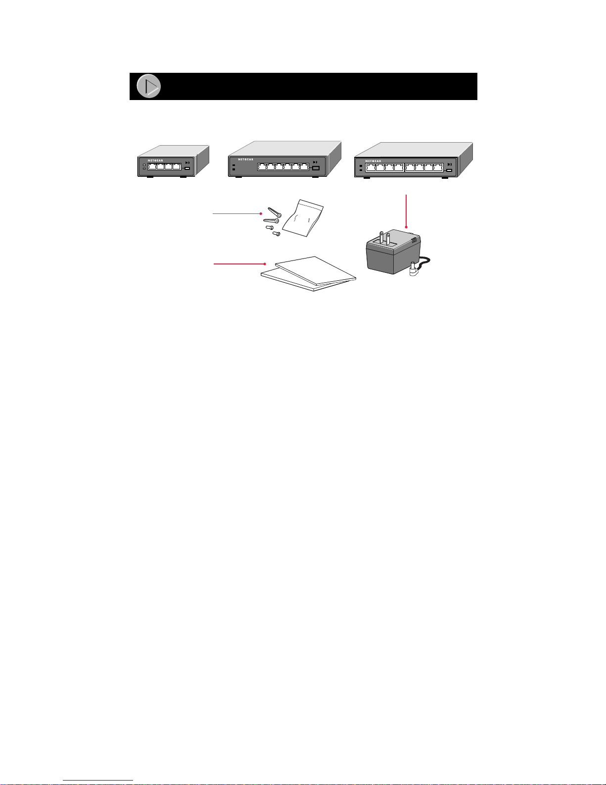
Package Contents
TP
Model EN104
10 BASE-T HUB
EN104
Mounting kit
Installation guide,
Warranty & Owner
Registration Card
Verify tha t your package contains the follo wing:
• Model EN104
or Model EN108
• Mounting kit (for wall instal lation)
hub Model EN106TP hub Model EN108TP hub
or or
TP
10 BASE-T HUB
TP
TP
hub, Model EN106
TP
Pwr
Col
hub
EN106
123456
Link/Rx Partition
TP
Normal/Uplink
hub,
TP
10 BASE-T HUB
Pwr
Col
EN108
1234 5678
Power
adapter
and cord
8722FA
• This installation guide
• W arranty & Owner Registration Card
• Power adapt er
Model EN104TP/EN106TP/EN108TP Ethernet Hub Installation Guide
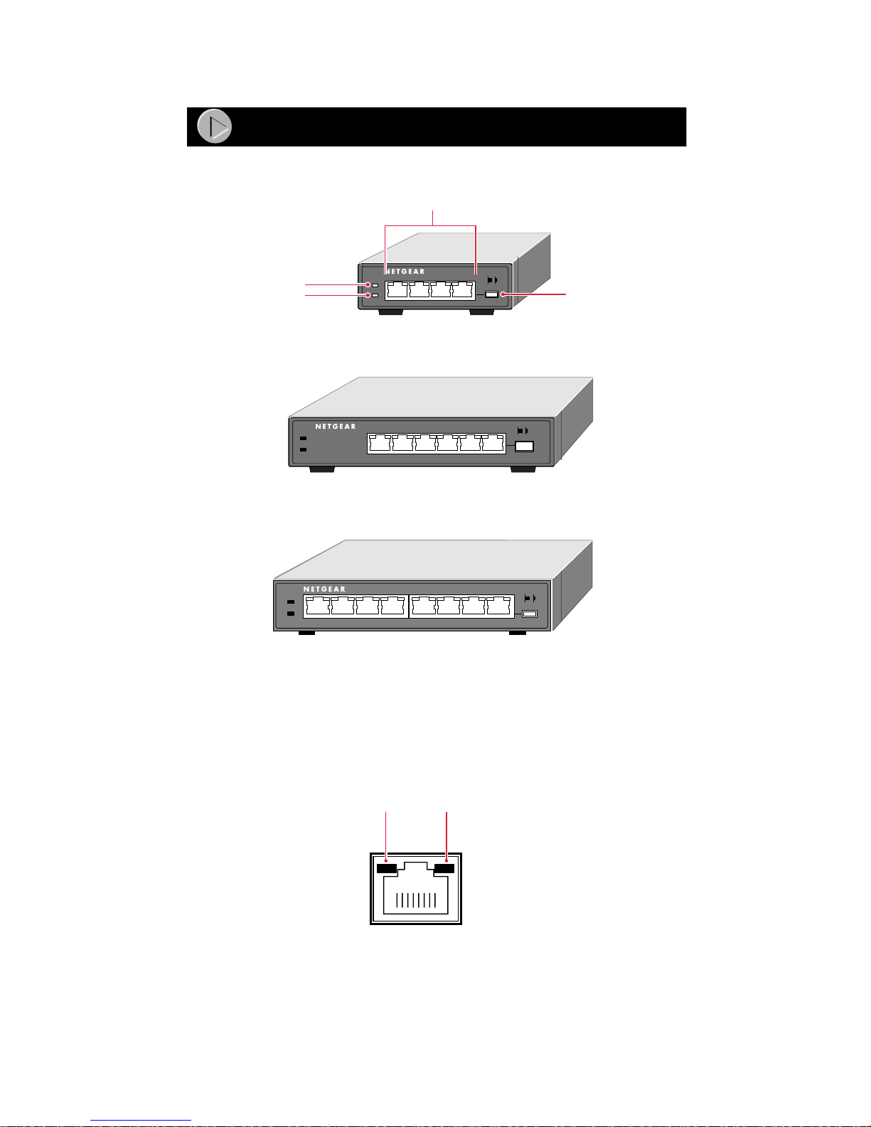
Product Illustration
Front Panel of the Model EN104TP hub
Pwr (Power)
Col (Collision)
Front Panel of the Model EN106
Pwr
Col
Front Panel of the Model EN108
10BASE-T ports
10 BASE-T HUB
EN104
Pwr
Col
TP
10 BASE-T HUB
EN106
123456
LINK Rx
TP
Normal/Uplink
push button
TP
hub
LINK Rx
Normal/Uplink
TP
hub
TP
10 BASE-T HUB
Pwr
Col
1234 5678
EN108
LINK Rx
8723FA
Vista 10BASE-T Network Ports with Built-in LEDs
TP
The front panel of the M odel EN104
Model EN106
TP
hub has six RJ-45 10BASE-T ports, and the Model EN108
hub has four RJ-45 10BASE-T ports, the
TP
hub has eight RJ-45 10BASE-T ports. Two LEDs—the Link LED and the Rx
LED—are built into each 10BASE-T port.
Link
LED
Rx
LED
8724EA
Model EN104TP/EN106TP/EN108TP Ethernet Hub Installation Guide
LEDs
The table below describe s the activity of the LEDs.
Label Color Activity Description
Pwr (Power) Green On Power is supplied to the hub.
Col (collision) Amber Blinking Data collision is occurring on the network. Note
that occasional collisions are normal.
Link
(located on the
top left corner of
each vista
10BASE-T port)
Rx
(located on the
top right corner
of each vista
10BASE-T port)
Green On The link between this port and the connected
device is good.
Green Blinking There is incoming data on t he port.
Normal/Uplink Push Button
The Normal/Uplink push button allows you to select Normal (MDI-X) wiring
for direct PC connection. The push button also allows you to select Uplink
(MDI) wiring for connection to a hub or a switch through port 4 on the Model
EN104
EN108
TP
hub, port 6 on the Model EN106
TP
hub. This uplink configuration eliminates the need to use a crossover
TP
hub, or port 8 on the Model
cable. The other 10BASE-T ports are permanently con figured for normal wiring
for connection to a PC.
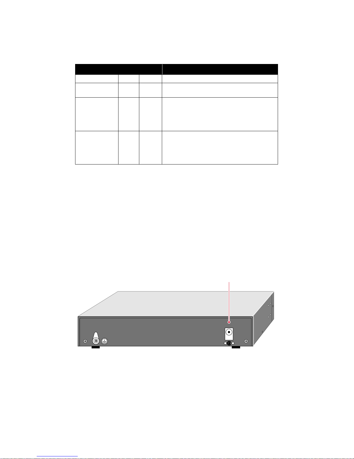
Rear Panel
The rear panel of the hub has a ground clip and a receptacle for the power
adapter.
Power
receptacle
5Vdc 800mA
– +
8730FA
Model EN104TP/EN106TP/EN108TP Ethernet Hub Installation Guide
Installation Procedures
Prepare the Site
Before you begin installing your hub, prepare the installation site. Make sure
your operating environment meets the operating environment requirements of
the equipment.
Characteristic Requirement
Temperature Ambient temperat ure bet ween 0° and 40° C (32° and 104° F).
No nearby heat sources such as direct sunlight, warm air
exhausts, or heaters.
Operating humidity Maximum relative humidity of 90%, noncondensing.
Ventilation Minimum 2 inches (5.08 cm) on all sides for cooling.
Adequate airflow i n room or wi rin g clos et.
Operating
conditions
Service access Minimum 12 inche s (19. 68 cm ) front and back for service access
Power Adequate power source within 6 feet (1. 83 m ).
Wiring hardware Wiring hardware, such as punchdown blocks or patch panels,
At least 6 feet (1. 83 m) to nearest source of elec tromagnetic
noise (such as photoc opy machine or arc wel der).
and maintenance.
Front an d bac k clear ance f o r cab les and wiri ng hardw are such as
punchdown blocks.
should be complete before instal li ng the hub.
Install the Hub
To install your hub on a flat surface, you do not need any special tools. Be sure
the hub is positioned with at least 2 inches of space on all sides for ventilation.
To install the hub on a wall, measure the distance between the mounting holes
on the back of the hub and mark the wall to match the location of the mounting
holes on the hub . At the marked l ocation, screw into the wall the two screws that
you received with the mounting kit included in your package contents. Be sure
to choose a location that is near the devices to be connected, is close to an
electrical outlet, and provides at least 2 inches of space all around the hub for
ventilation.
Model EN104TP/EN106TP/EN108TP Ethernet Hub Installation Guide
 Loading...