

Page 1
Nero WaveEditor Manual
Nero AG
Page 2

Copyright and Trademark Information
The manual for Nero WaveEditor and all its contents are protected by copyright and are the
property of Nero AG. All rights reserved. This manual contains materials which are protected
by internationally recognized copyright laws. This manual may not - in whole or in part - be
copied, transmitted, or otherwise reproduced without the express written permissi on of Nero
AG.
Nero AG rejects any claims that transcend the clauses of the guarantee rights. Nero AG
does not undertake any liability for the correctness of the content of the Nero WaveEditor
manual. The contents of the software supplied, as well as of the Nero WaveEditor manual,
may be changed without prior warning.
All trade names and trademarks are the property of the respective owners.
The trademarks mentioned here are only listed for information purposes.
Copyright © 2007 by Nero AG, Karlsbad, Germany.
REV 1.0, SW 4.00.0.0
Page 3

Contents
Contents
1 General information 6
1.1 About the manual 6
1.2 About Nero WaveEditor 6
2 Technical information 7
2.1 System requirements 7
2.1.1 Supported Formats 7
3 Terminology 8
4 Launching the program 9
4.1 Starting Nero WaveEditor via Nero StartSmart 9
5 User interface 10
5.1 Main screen 10
5.1.1 Menu bar 10
5.1.2 Toolbar 11
5.1.3 File display 12
5.1.4 Display window 12
6 Configuration 13
6.1 Device Settings 13
6.2 Editor Options 13
6.2.1 View tab 13
6.2.2 Folders tab 14
6.2.3 Save/Output Settings tab 14
6.2.4 VST Plug-Ins tab 15
6.3 Audio Format Settings 15
6.3.1 Decoder tab 15
6.3.2 Encoder tab 16
6.3.3 Converter tab 16
7 Audio 17
7.1 Playing Audio Files 17
7.2 Recording Audio files 17
7.3 Editing Audio Files 18
7.3.1 Fade out and fade in methods 20
7.3.2 Converting Sample Format 21
7.3.3 Implementing Pause Detection 22
Page 3
Page 4

Contents
7.3.4 Inserting a Test Signal in an Audio File 23
8 Filters 25
8.1 Tools 25
8.1.1 DeEsser 25
8.1.2 Dynamic Processor 26
8.1.3 Equalizer 26
8.1.4 Karaoke Filter 26
8.1.5 Noise Gate 27
8.1.6 Pitch Tuning 27
8.1.7 Stereo Processor 28
8.1.8 Time Correction 28
8.1.9 Transpose 28
8.2 Effects 29
8.2.1 Chorus 29
8.2.2 Convolution Reverb 29
8.2.3 Delay 30
8.2.4 Distortion 30
8.2.5 Doppler 31
8.2.6 Flanger 31
8.2.7 Loudness 31
8.2.8 Low Fidelity 31
8.2.9 Modulation 32
8.2.10 Multi-Tap Delay 32
8.2.11 Phaser 33
8.2.12 Pitch Bend 33
8.2.13 Pseudo Reverse 33
8.2.14 Re-analogue 33
8.2.15 Reverb 34
8.2.16 Stutter 34
8.2.17 Surround Expansion 35
8.2.18 Surround Reverb 35
8.2.19 Voice Modification 36
8.2.20 Wah-Wah 36
8.3 Enhancement 37
8.3.1 Band Extrapolation 37
8.3.2 Camera Denoiser 37
8.3.3 DC Offset Correction 37
8.3.4 Declicker 37
8.3.5 Declipper 38
8.3.6 DeHum 38
8.3.7 Filter Toolbox 38
8.3.8 Noise Reduction 39
8.3.9 Noise Analysis 39
8.4 Changing the sound of an audio file 40
Page 4
Page 5

Contents
9 List of figures 41
10 Index 42
11 Contact Information 45
Page 5
Page 6

General information
1 General information
1.1 About the manual
This manual is intended for all users who want to find out how to use Nero WaveEditor. It is
therefore structured according to operations and provides step-by-step instructions for what
you want to do..
In order to make best use of this manual, please note the following conventions:
Symbol Meaning
Indicates warnings, requirements, or notice messages that have
1. Start …
Æ
Î
OK
Chapter
[…] Indicates keyboard shortcuts for entering commands.
to be precisely followed.
Indicates additional information or notice messages.
A number at the beginning of a line indicates a request for
action. Carry out these actions in the order specified.
Indicates an intermediate result.
Indicates a result.
Indicates text passages or buttons that appear in the program
interface. They are shown in bold print.
Indicates references to other chapters. They are executed as
links and are shown in red and underlined.
1.2 About Nero WaveEditor
Nero WaveEditor allows you to record pieces of music, edit the corresponding audio files, for
example using various filters and sound enhancement methods, and finally burn them using
Nero Burning ROM or Nero Express.
With Nero WaveEditor, you edit the audio files non-destructively in real time. Thanks to an
internal reference-based audio format, the editing history is simultaneously stored so that
changes can also be undone. Various effects (e.g. chorus, delay, flanger, hall), numerous
tools (e.g. stereo processor, equalizer, noise gate), sophisticated improvement algorithms
(band extrapolation, noise suppression, declicker) as well as the filt ers and tools within Nero
WaveEditor are provided to assist you in editing your files.
Page 6
Page 7

Technical information
2 Technical information
2.1 System requirements
Nero WaveEditor is installed together with the full version of Nero. Its system requirements
are the same. You can find more detailed information on the system requirements in the
Nero QuickStart Guide.
In addition, the following requirements apply:
Microsoft® DirectX® 9.0b (or greater).
The latest version of DirectX® can be downloaded from the Internet under
http://www.microsoft.com/windows/directx and installed.
Minimum 5 MB free hard-disk space
16-bit Windows® compatible sound card and speakers or headphones
Installation of the latest WHQL-certified drivers is recommended. WHQL stands for
Windows Hardware Quality Labs and means that the device driver from Microsoft® is
certified compatible with Microsoft® Windows® and the relevant hardware.
2.1.1 Supported Formats
Nero WaveEditor allows you to open the following formats or to save files in these formats:
*.AC3
*.aif, .aiff
*.mp3
*.wma
*.mp4
*.ogg
*.wav, .wave
*.nwf
Page 7
Page 8

Terminology
3 Terminology
Sound is transmitted in air via waves. This characteristic gives rise to the following terms that
can be important for working with Nero WaveEditor:
Frequency is the number of vibrations per time unit. It is measured in Hertz.
In the case of a sound wave, the amplitude is perceived as volume (loudness). This is
the highest peak of a vibration.
Sampling rate indicates how often the sound card determines the sampling value of an
analog signal. It is measured in sampling values per second (Hertz or Hz). The higher the
sampling rate, the more precise the measurement, and the better the audio quality.
The sampling rate influences the frequency range. CDs use a sampling rate of 44,100 Hz,
in other words 44,100 sampling values per second. This means that frequencies of up to
22, 050 Hz can be recorded.
Bit depth indicates the precision with which a vibration will be captured. The higher the
bit depth, the more precise the capture, and the better the audio quality. CD's store audio
data in 16 bits. this means that each sample value can accept 65,536 possible values.
Page 8
Page 9
Launching the program
4 Launching the program
4.1 Starting Nero WaveEditor via Nero StartSmart
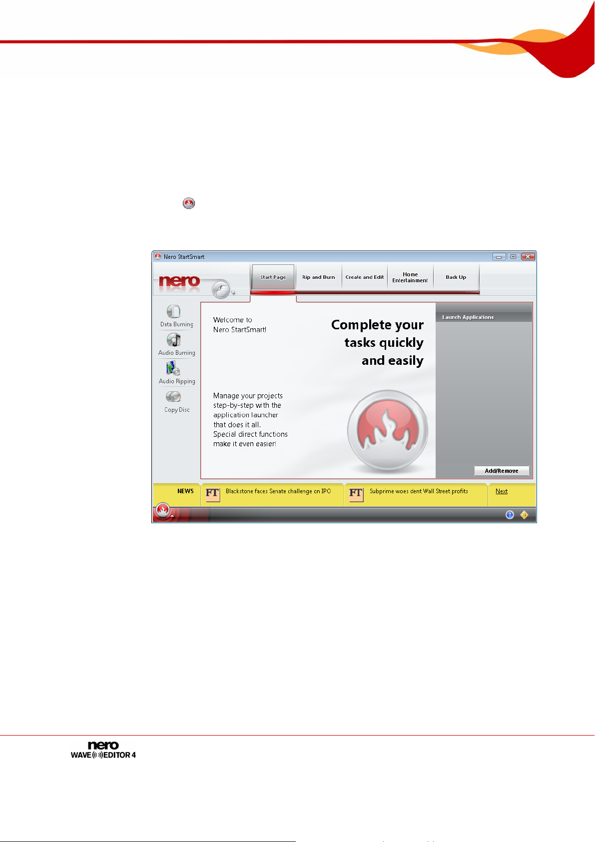
To start Nero WaveEditor via Nero StartSmart, proceed as follows:
1. Click on the Nero StartSmart icon.
Æ The Nero StartSmart window is opened.
2. Click the button.
Æ The list of Nero applications is displayed.
Fig. 1: Nero StartSmart
3. Select the Nero WaveEditor entry in the Applications list box.
Æ The Nero WaveEditor window opens.
Î You have launched Nero WaveEditor via Nero StartSmart.
Page 9
Page 10
User interface
5 User interface
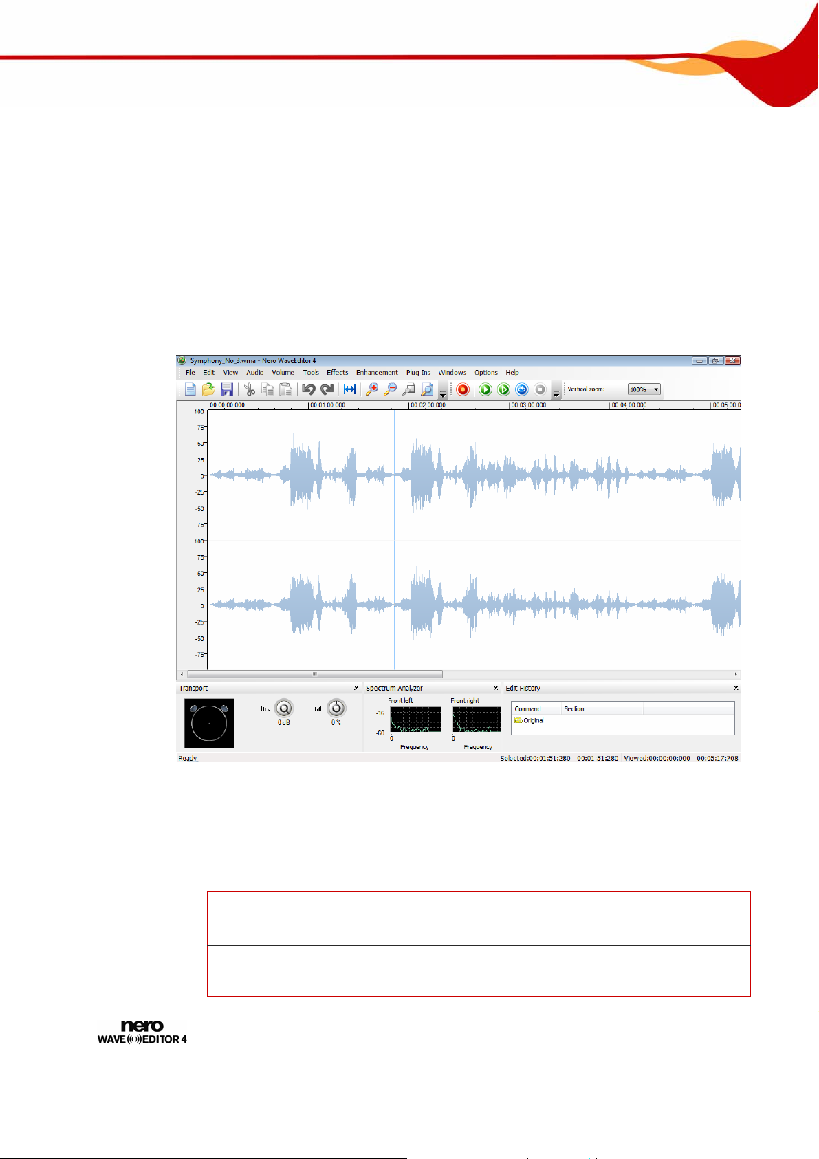
5.1 Main screen
When you start Nero WaveEditor the main screen is displayed. The main screen is divided
into the following sections:
Menu bar and toolbar
File display
Displays
5.1.1 Menu bar
The following setting options are available in the menu bar:
File
Edit
Page 10
Fig. 2: Nero WaveEditor main screen
Opens the File menu that contains file functions such as open,
save, and close with which you are already familiar from
Windows®.
Opens the Edit menu containing editing functions for the files
in the selection screen such as cutting, copying, and deleting
that you are already familiar with from Windows®. You can
Page 11

User interface
View
Audio
Volume
Tools
Effects
Enhancement
Windows
Settings
Help
also change the audio file, in different ways, insert files and
track splits and activate automatic silence detection.
Opens the View menu that offers the possibility of individually
adjusting the menu bar and toolbar, and enlarging or reducing
the view of the project. You can also change the view of the
audio file, show and hide windows and display information
about the loaded audio file.
Opens the Audio menu that offers the possibility of recording,
playing and stopping audio files.
Opens the Volume menu, which allows the volume of the
opened audio file to be edited.
Opens the Tools menu, which allows the opened audio file to
be edited using a variety of tools (see
Tools).
Opens the Effects menu, which allows the opened audio file
to be edited using a variety of effects (see
Effects).
Opens the Enhancement menu, which allows the sound of
the opened audio file to be edited (see
Enhancement).
Opens the Windows menu, which allows all windows to be
closed at once.
Opens the Settings menu, which allows the program to be
configured (see
Configuration).
Opens the Help menu, which allows the help file to be called
or information about Nero WaveEditor to be viewed.
5.1.2 Toolbar
The following setting options are available in the toolbar:
Creates an audio file.
Opens an existing audio file.
Saves the audio file.
Cuts out the selected section and saves it on the clipboard
Copies the selected section and saves it on the clipboard
Pastes the contents of the clipboard at the selected point.
This undoes the last action.
Restores the last action that you have undone.
Selects the entire audio file.
Zooms into the audio file.
Zooms out from the audio file.
Zooms into the audio file so that the selected section is displayed in a manner
that fills the screen.
Zooms out from the audio file so that the whole file can be seen.
Page 11
Page 12

User interface
5.1.3 File display
The opened file is displayed in the file display as a peak file with the wave display as
standard. It is also possible to change the display to spectrogram display or wavelet display.
5.1.4 Display window
The following setting options are available in the View menu:
Level Meters
Spectrum Analyzer
Edit History
Opens the Transport window, the left half of which
visualizes the room sound. You can also reproduce the
audio file in the right half of the window, also changing
the volume and the use of the loudspeakers.
Opens the Spectrum Analyzer window in which the
frequencies of the audio file are displayed graphically
during playback.
Opens the Edit History window which lists all the editing
steps of the audio file. You can also return to any edit
phase here and restore the original state of the audio file.
5.1.4.1 Showing a display window or toolbar
To show a display window or toolbar, proceed as follows:
1. Click on the View > Required Display Window menu or toolbar.
Î The display windows are shown at the bottom of the main screen. You can move the
display windows about as required and change their size.
The toolbars are shown under the menu bar. These can also be moved using the
mouse.
Page 12
Page 13

Configuration
6 Configuration
You can configure Nero WaveEditor to suit your needs. The following adjustable sections are
available to you.
Device settings (see Device Settings)
Editor Options (see Editor Options)
Audio Format Settings (see Audio Format Settings )
6.1 Device Settings
You can adjust device settings in the Device Settings window.
You reach this window via the menu bar under Options > Device Settings.
The following setting options are available in the Device Settings window:
Input Device
pull-down menu
Output Device
pull-down menu
Displays the input device.
Displays the output device.
6.2 Editor Options
The editor options are customized in the Editor Options window.
You reach this window via the menu bar under Settings > Editor Options..
6.2.1 View tab
The View tab offers the following setting possibilities:
Show axis to the left of
the audio visualization
check box
Show time rules above
the audio visualization
check box
Trace playback
position line while
playing
check box
Use green on black
color set
check box
Displays an axis to the left of the peak file of the audio
file.
Displays an axis above the peak file of the audio file.
Uses a red line to show the position of the playback in
the audio file.
Displays the peak file in green and the background in
black. The default is for the peak file to be shown in blue
and the background in white.
Page 13
Page 14

Configuration
6.2.2 Folders tab
The Folders tab offers the following setting possibilities:
Temporary folder
input field
Peak File Directory
input field
Always recreate peak
files
check box
My Music Directory
input field
Always start file open
dialog in My Music
folder
check box
Defines the folder in which temporary files are stored.
The folder should be located on a drive with plenty of
storage space.
Specifies the default folder where peak files are stored.
Peak files are cache files that Nero WaveEditor uses to
more quickly open audio files. The folder should be
located on a drive with plenty of storage space.
Always creates a new peak file when an audio file is
opened. Otherwise the peak files are stores temporarily
in a directory and are called up again there.
Specifies the default folder where files are stored.
When calling the Open dialog box the system will always
first show the folder that is specified in the My Music
folder input field.
6.2.3 Save/Output Settings tab
The Save/Output Settings tab offers the following setting possibilities:
Use dithering when
converting to lower bit
depths
check box
Pull-down menu
Noise shaping filter
Restore wave output
volume when closing
Nero WaveEditor
check box
Bit depth during
playback:
pull-down menu
Overlays sound errors that arise when converting to a
lower bit depth with a white noise that is hardly noticed
by human hearing. If there is no dithering, clearly audible
interference can be heard when converting to lower bit
depths.
Specifies the type of noise shaping
IIR filter (2nd order): Infinite Duration Impulse
Response. Uses IIR-filters. Second order means that
sound is attenuated by 12 dB. IIR filters generally
achieve a better audio quality than FIR filters.
FIR filter (3 taps): Finite Impulse Response Filter. Uses
FIR filters. This entry is selected by default.
Restores the volume of the audio file when Nero
WaveEditor is closed.
Specifies the bit depth during the playback of the loaded
audio file.
Page 14
Page 15

Configuration
Pull-down menu:
Play surround audio as
6.2.4 VST Plug-Ins tab
The VST Pug-Ins tab offers the following setting possibilities:
Display section
Installed VST Plug-Ins:
Delete button Deletes the selected VST plug-in
Button
Add plug-in
Button
Scan folder
Specifies how surround audio is played back.
Multichannel Audio
Plays back surround audio with all channels.
Stereo with Nero HeadPhone (virtual surround):
Plays back surround audio filtered down as stereo and a
virtual surround effect is generated for headphones,
Stereo with Nero VirtualSpeakers (virtual surround):
Plays surround audio filtered down as stereo and a
virtual sound effect is generated for speakers.
Shows the currently installed VST plug-ins
Opens the Open dialog box. Installs a new VST plug-in
Opens the Open dialog box. Searches for new VST
plug-ins in the specified folder.
6.3 Audio Format Settings
Use the Audio Format Settings window to adjust the audio settings.
You reach this window via the menu bar under Options > Audioformat Settings.
6.3.1 Decoder tab
The Decoder tab offers the following setting possibilities:
Button
Configure
Button
Info
Button
Move Up
Button
Move Down
Button
Artist/Title
Information Source
Opens a dialog box where additional settings can be made
for the selected decoder.
This button is not available for all decoders.
Opens the About dialog box where you can view
information about the selected decoder.
This button is not available for all decoders.
Moves the decoder up one entry.
Moves the decoder down one entry.
Opens the dialog box Get Artist / Title Information which
shows the source from which information relative to artist
and title will be input.
Page 15
Page 16

Configuration
6.3.2 Encoder tab
The Encoder tab offers the following setting possibilities:
Button
Configure
Button
Info
Button
Artist/Title
Information Source
6.3.3 Converter tab
The Converter tab offers the following setting possibilities:
Button
Configure
Button
Info
Button
Artist/Title
Information Source
Opens a dialog box where additional settings can be made
for the selected encoder.
This button is not available for all encoders.
Opens the About dialog box where information about the
selected encoder is displayed. This button is not available
for all encoders.
Opens the dialog box Get Artist / Title Information which
shows the source from which information relative to artist
and title will be input.
Opens a dialog box where additional settings can be made
for the selected converter.
This button is not available for all converters.
Opens the About dialog box where you can view
information about the selected converter.
This button is not available for all converters.
Opens the dialog box Get Artist / Title Information which
shows the source from which information relative to artist
and title will be input.
Page 16
Page 17

Audio
7 Audio
7.1 Playing Audio Files
To play an audio file, proceed as follows:
1. Click on the File > Open menu.
Æ The Open window appears.
2. Select the audio file you want to open in the file system and click on the Open button.
Æ The two channels of the audio file are presented as peak file.
3. To play back to complete audio file, click on the Audio > Play All menu.
4. If you have marked a section of the audio file and only want to play this section, click on the
Audio > Play Section menu.
5. If you want to play back the file without interruption, click on the Audio > Play Looped
menu.
6. To stop playback, click on the Audio > Stop menu.
Î You have played back an audio file.
7.2 Recording Audio files
You can use Nero WaveEditor to connect many types of playback devices to the computer
and to record the medium played there.
Fig. 3: Recording Console window while recording an audio file
The Recording Console window offers you the following setting options:
Returns to the start of the recording so that this can be
Page 17
overwritten.
Pauses recording.
Page 18

Audio
Overwrite existing
recording
pull-down menu
Insert into
recording
radio button
Audio input line
pull-down menu
Digital Monitoring
check box
Input level
control
To record an audio file, proceed as follows:
Records an audio file.
Goes to the end of the recording so that recording can be
resumed there.
Overwrites the existing recording or audio file which is open
in Nero WaveEditor.
Inserts the recording into the audio file at the point where
the marker is located.
Specifies the audio input.
Activates the Input level control.
Specifies the volume of the recording. The recording should
be in the yellow area in the spectrum analyzer.
1. Click on the Audio > Capture menu.
Æ The Recording Console window will open.
2. Make the desired capture settings.
3. Click on the button to make a recording.
4. Click on the button to interrupt the recording.
5. Click on the OK button if you want to insert the recording into the file display.
Î You have created an audio file.
7.3 Editing Audio Files
To edit an audio file, proceed as follows:
1. If you want to play back the highlighted part of the audio file in reverse, click on the Edit >
Reverse menu.
2. To insert a test signal into the audio file, click on the Edit > Insert Test Signal menu (see
Inserting a Test Signal in an Audio File).
3. To convert the sample format, click on the Edit > Convert Sample Format menu (see
Converting Sample Format).
4. If you want silences in a song to be detected automatically so as to be able to skip these
when playing the audio file, click on the Edit > Pause Detection menu (see
Pause Detection
).
Implementing
5. If you want to insert a track split in the audio file to be able to skip directly to this point, click
on the Edit > Insert Track Split menu.
6. If you want to save a single track produced by inserting track splits as a file:
1. Click on the Edit > Save Tracks as Files menu.
Page 18
Page 19

Audio
Æ The Save Tracks as Separate Files window is opened.
2. Select the track you want to save, name it and select the required file format.
3. Click on the OK button.
7. If you want to fade out the volume of the marked section of the audio file , click on the
Volume > Fade out > required hide method menu (see
Æ The change in volume in the marked section is displayed graphically in the file display.
Fade out and fade in methods).
8. If you want to fade in the volume of the marked section of the audio file , click on the Volume
> Fade in > required show method menu (see
Æ The change in volume in the marked section is displayed graphically in the file display.
Fade out and fade in methods).
9. If you want to normalize the frequencies of the marked part of the audio file to a particular dB
value.
Normalizing in audio technology is the process whereby analog and/or digital audio data is
raised to a uniform volume level.
1. Click on the Volume > Normalization menu.
Æ The Normalization window will open.
2. Move the Normalize to control to the required position. The set dB value will appear in the
display panel.
3. Click on the OK button.
10. If you want to raise or lower the volume of the marked section of the audio file:
Raising the volume raises all frequencies of the audio file by the specified dB value.
Lowering the volume reduces all frequencies by the specified dB value.
1. Click on the Volume > Volume Change menu.
Æ The Volume Change window will be opened.
2. Move the Volume Change control to the required position. The set dB value will appear in
the display panel.
3. Click on the OK button.
11. If you want to mute the marked section of the audio file, click on the Volume > Mute menu.
Æ The change in volume in the marked section is displayed graphically in the file display.
12. If you want to change the marked section of the audio file with a tool, click on the Tool menu
Tools).
(see
13. If you want to change the marked section of the audio file with an effect, click on the Effect
menu (see
Effects).
14. If you want to change the marked section of the audio file with an enhancement tool, click on
the Enhancement menu (see
Enhancement).
Î You have edited the audio file.
Page 19
Page 20

Audio
7.3.1 Fade out and fade in methods
The following options are available in the Volume > Fade out menu:
Fade out Sinusoidal
Fade out Exponential
Fade out Linear
Fade out Logarithmic
The following options are available in the Volume > Fade in menu:
Fade in Sinusoidal
Fade in Exponential
Fade in Linear
Fade in Logarithmic
Page 20
Page 21

Audio
7.3.2 Converting Sample Format
The Edit menu allows you to convert the sample format.
Fig. 4: Converted Sample Format Settings window
The Converted Sample Format Settings window offers you the following setting options:
Sample Rate
drop-down menu
Bit Depth
pull-down menu
Channels
radio buttons
Down conversion
method
combo box
Antialiasing Filter
combo box
To convert the sample format, proceed as follows:
Provides different sample rates for selection.
Provides different bit depths for selection.
Provides different output types for selection. You can create a
Surround audio file with five or seven channels by selecting
Surround 5.1 and 7.1.
Converts a Surround audio file into a normal stereo-audio file,
a stereo audio file with artificial Surroundsound for headsets
or a stereo audio file with artificial Surroundsound for
speakers. Only available with Surround audio files.
This provides different kinds of antialiasing-filters.
1. Click on the Edit > Convert Sample Format menu.
Æ The Converted Sample Format Settings window will be opened.
2. Define the required settings in the Converted Sample Format Settings window.
3. Click on the OK button.
Î You have converted the sample format.
Page 21
Page 22

Audio
7.3.3 Implementing Pause Detection
The Edit menu allows you to implement automatic pause detection for the audio file.
Fig. 5: Pause Detection window
The Pause Detection window offers you the following setting options:
Provides different actions for selection. You can insert track splits
Action field
Pause Length
input field
Minimum
Song length
input field
Threshold
control
To implement automatic pause detection, proceed as follows:
at the detected pauses, delete the detected pauses or delete the
detected pauses and replace them with track splits.
Defines the minimum length of a pause in the audio file if it is to be
detected automatically. The number is specified in seconds.
Defines the minimum length of a song if it is to be recognized as a
whole song. The number is specified in seconds.
Defines the threshold for the volume below which the tracks of the
audio file will be detected as pauses.
1. Click on the Edit > Pause Detection menu.
Æ The Pause Detection menu will be opened..
2. Define the required settings in the Pause Detection window.
3. Click on the OK button.
Î You have now implemented automatic silence detection.
Page 22
Page 23

Audio
7.3.4 Inserting a Test Signal in an Audio File
The Test Signal-Generator window allows you to insert a test signal in the audio file.
Fig. 6: Test Signal Generator window
The Test Signal Generator window offers you the following setting options:
Duration
input field
Specifies the duration of the test signal.
Defines that the test signal is reproduced as a tone. Also
Tones
radio button
activates the area containing the setting options for the
wave form, start frequency and end frequency of the test
signal.
Wave form
combo box
Start Frequency
input field
End frequency
input field
Noise
radio button
Color
combo-box
Amplitude
control
Specifies the wave form that the test signal should have.
Specifies the start frequency of the test signal.
Specifies the end frequency of the test signal.
Defines that the test signal is reproduced as a noise. Also
activates the area that defines the type of noise.
Specifies the type of noise. White is a loud noise, Pink a
medium noise and Brown a quiet noise.
Specifies the amplitude of the test signal both for sound and
noise.
1. Click on the Edit > Insert Test Signal menu.
Æ The Test Signal Generator window will be opened.
Page 23
Page 24

Audio
2. Make the required settings for the test signal to be inserted.
3. Click on the OK button.
4. Now define the range of the test signal by moving the arrows at the bottom of the file display.
5. To exclude an audio file before the test signal, move the blue-green arrows at the start of the
test signal at the top of the file display from left to right.
6. To insert an audio file after the test signal, move the blue-green arrows at the end of the test
signal at the top of the file display from left to right.
7. Click on the OK button.
Î You have inserted a test signal in the audio file.
Page 24
Page 25

Filters
8 Filters
You can change the sound of an audio file in a variety of ways. The following menus are
available for this purpose:
Tools
Effects
Enhancement
The following setting options are available in all windows:
Active
Channels
Bypass
Process offline
Plays the audio file changed by the filter.
Stops playing.
Provides the active channels for selection. You can switch the
channels on and off separately.
Retains the change by the filter for the duration of the activation.
This enables you to listen to the unedited file and the edited
version alternately.
Processes the change to the audio file offline. This enables the
changed file to be played back with a weaker processor without
jerking.
Provides both predefined and personally produced profiles for
selection.
Creates a new profile with the current settings.
Deletes the selected profile.
8.1 Tools
8.1.1 DeEsser
The DeEsser tool is used to filter out unpleasant hissing sounds (sibilants) from recorde d
speech and song.
Threshold
Attenuation
Attack Time
Release Time
Specifies the level after which hiss is to be suppressed as a dB
value. If this value is very low, even very quiet hiss will be
suppressed.
Specifies the extent to which hiss is to be damped if it is not
filtered out completely.
Specifies how long the hiss has to be in order to be detected.
Specifies for how long the hiss is to be filtered.
Page 25
Page 26

Filters
8.1.2 Dynamic Processor
You can use the Dynamic Processor tool to adjust the ratio between the input and output
volume. This makes it possible, for example, to emphasize quiet noises, thereby lending
more dynamism to the audio file.
Characteristics
Attack Time
Release Time
Movie
8.1.3 Equalizer
The Equalizer tool allows you to emphasize certain frequencies, specifying the amplitude
and bandwidth.
Frequency
Response
Graph
Center
Frequencies
Emphasis
Bandwidths
Low Shelf
Cut Off
Gain
High Shelf
Cut Off
Gain
Shows the ratio of input volume to output volume. In this case
the y-axis is the output, and the x-axis the input.
Specifies the time it takes before the full effect is heard.
Specifies the time it takes before the effect is no longer heard.
Processes all Surround channels for the same parts. This can
only be activated when a Surround audio file is being processed.
Shows the frequency response. The y-axis represents the
amplitude and the x-axis the frequency.
Indicates the distribution of the handles on the x-axis. You can
enter the values (in Hz) of the center frequencies in the fields.
Specifies the amplification of the signal on the y-axis of the curve
in the diagram.
Indicates whether the bandwidth of the medium frequency rises
and falls steeply or gently. You can set a value between 0.1 and
3 octaves with the control.
Increases or decreases low frequencies.
Allows the filter to start after a certain frequency.
Specifies the degree of increase or decrease.
Increases or decreases high frequencies.
Allows the filter to start after a certain frequency.
Specifies the degree of increase or decrease.
8.1.4 Karaoke Filter
The Karaoke Filter tool filters frequencies from the audio file that are the same on both
channels of a stereo file. On older recordings this is usually the voice. However, if the voice
us not distributed evenly on both channels, you can perform some fine tuning.
Vocal Pan
Gain
Compensation
Page 26
Specifies the channel and intensity with which the voice is to be
filtered.
Increases the volume of the audio file, which had become quieter
because the filter was applied.
Page 27

Filters
Vocal
Frequency
Band
Lower
Frequency
Upper
Frequency
8.1.5 Noise Gate
The Noise Gate tools suppresses quiet sections in the signal transmission. For example, it
helps prevent noise. The Noise Gate belongs to the category of dynamic processors.
Threshold
Attack Time
Release Time
Channel Mode
Specifies the frequency band of the voice.
Specifies the lower frequency limit for the voice. This is typically a
value of 100 Hz.
Specifies the upper frequency limit for the voice. This is typically
a value of 7000 Hz.
Specifies the minimum dB value below which the audio file is to
be muted. In other words, the gate is closed if the dB value is too
low.
Specifies the time required to reopen the gate in milliseconds
after the threshold has been exceeded, in other words to restore
the sound of the audio file.
Specifies the time in milliseconds required to close the gate, in
other words to mute the audio file, after the level has dropped
below the threshold.
Only relevant for audio files in stereo format.
If the Linked radio button is enabled, the noise gate for both
channels is opened as soon as one or both of the two channels
exceeds the threshold.
If the Independent radio button is enabled, the noise gate closes
or opens both channels independently when the threshold is
reached.
8.1.6 Pitch Tuning
The Pitch Tuning tools changes the pitch, for example of the voice, for a short time, so that
incorrectly sung tones can be corrected.
Correction
Corrected
Reference
Binding
Scale:
Vibrato
Frequency
Depth
Page 27
Corrects incorrect sounds.
Shows the level of correction on the basis of the movement of
the green arrow.
Specifies the reference sound used for correction..
Specifies for how long the sound is to be corrected. The lower
the value, the shorter the correction period for an incorrect
sound.
Provides a variety of scales for selection. The most commonly
used scale in Europe is Equally Tempered Chrome.
Adds sound changes, both high and low. This causes the voice
to "vibrate".
Indicates the frequency of the sound changes.
Indicates the intensity of the sound change.
Page 28

Filters
8.1.7 Stereo Processor
The Stereo Processor tool allows you to manipulate the stereo sounds.
Left Out
Left In
Right In
Right Out
Left In
Right In
Stereo Settings
Phase Offset
Stereo
Broadening
Specifies the output intensity of the left hand loudspeaker
Specifies the intensity of the left input signal for the left hand
loudspeaker.
Specifies the intensity of the right input signal for the left hand
loudspeaker.
Specifies the output intensity of the right hand loudspeaker
Specifies the intensity of the left input signal for the right hand
loudspeaker.
Specifies the intensity of the right input signal for the right hand
loudspeaker.
Provides further stereo sound settings.
Compensates for differences in run-time between the left and
right channel.
Makes a mono recording sound like a stereo recording. This
setting will give a stereo recording an even broader feeling.
8.1.8 Time Correction
The Time Correction tool changes the playback speed, but not the pitch.
Timescale
Modification
Factor
Percentage
Beats per
Minute
Optimization
8.1.9 Transpose
The Transpose tool changes the pitch. The length of the audio file can be changed or
retained. However, it is possible to adjust the length of the audio file to the faster playback
speed.
Interval
Fine-tune
Maintain
Original
Length
Offers two different ways to change the playback speed of the
audio file.
Changes the playback speed in percent. The change can either
be set on the control or entered in the input field.
Changes the playback speed to beats per minute (BpM).
Specifies the type of music of the audio file to be altered, so as
to optimize speed changes for this file.
Changes the interval in the audio file.
Permits fine tuning if retaining the original length causes
distortion.
Retains the original length of the audio file.
Page 28
Page 29

Filters
8.2 Effects
8.2.1 Chorus
The Chorus effect creates an echo effect, which when applies to a recorded voice, ma kes it
sound like there is a choir singing in the background.
Modulation
Depth
Frequency
Delay
Filters
Low Pass
Mix
Effect
Dry Signal
Stereo Chorus
Changes the copied signal
Specifies the degree of the change in pitch
Specifies the frequency of the change in pitch (oscillations).
Specifies the delay with which the copy is played in comparison
with the original signal.
Allows a low pass filter to be activated.
Reduces frequencies above the specified Hertz rate and allows
low frequencies beneath the specified value to pass almost
unfiltered.
Mixes the original signal with the copied signal.
Specifies the intensity of the copied signal.
Indicates the intensity of the original signal.
Gives the processed part of the audio file a more "stereo-like"
sound
8.2.2 Convolution Reverb
The Convolution Reverb effect transfers the convolution reverb conditions of a reference
file and adjusts the audio file to the relevant reverb conditions.
Select Impulse
Response
Impulse
Response Gain
Gain
Pre-Delay
Mix
Dry Signal
Effect
Opens the source file for the impulse response from which the
reverb effect for the audio file to be edited is generated.
Displays the signal of the impulse response.
Displays the frequency limit for the reverb. The y-axis of the
curve specifies the gain of the reverb effect in the diagram, while
the x-axis shows the frequency.
Switches between a linear and logarithmic scale for the limiting
frequency graphic.
Specifies the length of time required by the sound to be deflected
from an obstacle, thereby indicating the intensity of the echo.
Mixes the original signal with the copied signal.
Indicates the intensity of the original signal.
Specifies the intensity of the copied signal.
Page 29
Page 30

Filters
8.2.3 Delay
The Delay effect creates an echo using a copy of the original signal which is played back
with a delay.
Delay
Delay Time
Feedback
Mix
Dry Signal
Effect
8.2.4 Distortion
The Distortion effect is used for guitars. This means that a recording of acoustic guitar can
be distorted to sound like an electric guitar.
Distortion
Method
Drive
Hardness
Pre-Filtering
Lower Cutoff
Upper Cutoff
Post-Filtering
Lower Cutoff
Upper Cutoff
Mix
Dry Signal
Effect
Provides setting options for the copy of the original signal.
Specifies the delay in playing back the copied signal.
Specifies how many copies of the original signal are to be made.
Mixes the original signal with the copied signal.
Indicates the intensity of the original signal.
Specifies the intensity of the copied signal.
Distorts the original signal.
Offers a variety of distortion options, e.g. an old megaphone.
Indicates the intensity of the interference.
Specifies the hardness of the distortion.
This can only be adjusted if the entries Tube, Fuzz3 and
Variable clipping have been selected in the Method combo
box..
Filters the original signal before it is distorted.
Specifies the lower limit of the frequency band for the original
signal.
Specifies the upper limit of the frequency band for the original
signal.
Filters the distorted signal.
Specifies the lower limit of the frequency band for the edited
signal.
Specifies the upper limit of the frequency band for the edited
signal.
Mixes the original signal with the edited signal.
Indicates the intensity of the original signal.
Specifies the intensity of the copied signal.
Page 30
Page 31

Filters
8.2.5 Doppler
The Doppler effect simulates a noise source passing by and the resulting special auditory
features.
8.2.6 Flanger
The Flanger effect is a guitar effect that distorts the sound by playing back a copy of the
original signal with a delay. The copy is changed by means of modulation, so that the sound
is distorted in a characteristic way.
Graphic
Diameter
Duration
Modulation
Depth
Frequency
Mix
Dry Signal
Effect
Stereo Flanger
Shows the target and end point of the movement of the noise
source. The listener is at the center of the graphic.
The pattern of the movement can be changed using the straight
lines in the graphic.
Specifies the diameters of the movement radius.
Specifies the duration of the movement.
Changes the copied signal
Specifies the degree of the change in pitch.
Specifies the frequency of the change in pitch.
Mixes the original signal with the copied signal.
Indicates the intensity of the original signal.
Specifies the intensity of the copied signal.
Gives the processed part of the audio file a more "stereo-like"
sound
8.2.7 Loudness
The Loudness effect increases the volume of the audio file without increasing the maximum
value of the amplitude (value 1) by raising the amplitude of other areas in the audio file. The
file is thus louder overall without exceeding value 1 of the amplitude.
Aimed Gain
8.2.8 Low Fidelity
The Low Fidelity effect creates interference effects, so called quantification errors, by
reducing the bit rate. Noise can be heard when the bit rate is dramatically reduced. If the
sample rate is reduced, the audio file sounds duller and less detailed.
Bit Depth /
Sample Rate
Bit depth
Sample Rate
Page 31
Specifies the degree of amplification.
Shows the change in the two controls under the graphic.
Specifies the bit depth. Music CDs have a bit depth of 16, for
example.
Specifies the sample rate. Music CDs hav e a sample rate of
44100 Hz.
Page 32

Filters
8.2.9 Modulation
The Modulation effect allows the amplitude and frequency to be changed separately.
Amplitude
Modulation
Frequency
Amplitude
Range
Modulation
Signal
Blend Edges
Frequency
Modulation
Frequency
Depth
Modulation
Signal
Blend Edges
Mix
Dry Signal
Amplitude
Modulated
Frequency
Modulated
Shows the amplitude of the audio signal.
Specifies the frequency of the signal.
Specifies the signal volume.
Provides different signal forms.
Balances different end and start values.
Only activated for self-produced signals.
Shows the frequency of the audio signal.
Specifies the frequency of the signal.
Specifies the depth of the signal.
Provides different signal forms.
Balances different end and start values.
Only activated for self-produced signals.
Mixes the original signal with the modulated amplitude signal and
the modulated frequency signal..
Indicates the intensity of the original signal.
Specifies the intensity of the signal with the modulated
amplitude.
Specifies the intensity of the signal with the modulated
frequency.
8.2.10 Multi-Tap Delay
The Multi-Tap-Delay effect allows several copies of the original signal to be created and
played back with a delay. This creates the reverb effect.
Active tap
Graphic
Delay
Emphasis
Pan
Feedback
Type
Feedback Gain
Mix
Dry Signal
Effect
Page 32
Provides several copies for selection.
Shows the copy and its copies.
Specifies the intervals at which copies are to be played back.
Specifies the volume/intensity of the copies.
In the case of stereo files, this indicates the speaker on which
the copies are to be heard.
Offers settings for the copies of the copy of the original signal.
Provides different filters for the copied signals for selection.
Specifies the volume of the copies that are played back after the
time specified with the Delay control.
Mixes the original signal with the edited copies.
Indicates the intensity of the original signal.
Specifies the intensity of the edited signal.
Page 33

Filters
8.2.11 Phaser
The Phaser effect is a guitar effect that distorts the sound by playing back a band-filtered
copy of the original signal with a delay.
Modulation
Modulation
Function
Frequency
Settings
Lower Limit
Upper Limit
Bandwidth
Stereo Flanger
Mix
Dry Signal
Effect
Provides settings for modulating the copied signal.
Provides different signal forms.
Specifies the frequency of the copied signal.
Offers settings for band filtering.
Specifies the lower limit of the frequency band.
Specifies the upper limit of the frequency band.
Indicates the bandwidth of the signal.
Gives the processed part of the audio file a more "stereo-like"
sound
Mixes the original signal with the edited copy.
Indicates the intensity of the original signal.
Specifies the intensity of the edited signal.
8.2.12 Pitch Bend
The Pitch Bend effect changes the pitch over the length of the audio file with the help of a
"speed curve". The length of the audio file can be changed or retained.
Graphic
Pitch Range
Keep Length
8.2.13 Pseudo Reverse
The Pseudo-Reverse does not reverse the entire audio file, but rather divides it into small
sequences that are played back in reverse order in "normal" direction . This means that the
content of the audio file can still be recognized and creates the effect of reversing the order
of play.
Reverse
Duration
Shows the pitch over the length of the audio file.
Sets the y-axis of the graphic. The higher the value, the more
noticeably the pitch can be changed.
Maintains the length of the audio file when the check box is
enabled.
Indicates how long the sequences should be to be played in
reverse.
8.2.14 Re-analogue
The Re-Analogue effect adds effect to the audio file that make it sound artificially older.
Noise
Levels
Page 33
Adds noise to the audio file.
Specifies the intensity of the noise.
Page 34

Filters
Retro-Radio
Levels
Gramophone
Clicks
Crackle
Source
Humming
Levels
Overtones
Curve
Frequency
Makes the audio file sound slightly distorted, similar to the effect
of an old radio.
Specifies the intensity of the distortion effect.
Adds the effect of scratches and dust on an old record.
Specifies the frequency and intensity of scratches as on a vinyl
record.
Specifies the frequency and intensity of crackle as on a vinyl
record.
Offers a choice of different record types.
Adds a low frequency hum
Indicates the intensity of the hum.
Specifies the number of overtones the frequency has.
Specifies the steepness of the transitions between high and low
level. This setting make the hiss sound "scratchy".
Specifies the hum frequency.
8.2.15 Reverb
8.2.16 Stutter
Reverb creates a reverb effect.
Reverb Time
Room Size
Brightness
Mix
Dry Signal
Effect
The Stutter effect allows there different stutter effects to be applied.
Graphic
Silence
Duration
Signal Duration
Mode
Mute
Stretch
Specifies the duration of the reverb.
Specifies the size of the imaginary room in which the reverb is to
be generated.
Specifies the brightness of the reverb.
Mixes the original signal with the edited copy.
Indicates the intensity of the original signal.
Specifies the intensity of the edited copy of the signal.
Shows the length of the silence on the y axis and the signal
length on the x axis.
Specifies the length of silences or repetitions.
Specifies the length of the signals to be repeated.
Provides three different stutter modes.
Plays back the audio file in mute mode. The file is played for the
period set using the Signal Duration control and muted for the
period set with the Silence Duration control. The file retains its
file length.
Plays back the audio file in stretch mode. The file is played for
the period set using the Signal Duration control and muted for
the period set with the Silence Duration control. The length of
the file changes because after muting at the appropriate place in
Page 34
Page 35

Filters
Repeat
8.2.17 Surround Expansion
The Surround Expansion effect is only available if you are editing a Surround audio file (5.1
or 7.1). This offers advanced Surround Sound settings.
Expansion
Front Channels
Side Channels
Surround
Channels
the file, playback resumes where the last playback ended.
Plays back the audio file in Repeat mode. The file is played back
for the length of time set using the Signal Duration control. The
same section of the audio file is then played again for the length
of time set with the Silence Duration control. After this section
has been played again, playback resumes at the point at which
the playback specified by the signal length ends, and so on.
Indicates the degree of expansion.
Extends the expansion to include the front channels.
Extends the expansion to include the side channels.
Extends the expansion to include the Surround channels.
8.2.18 Surround Reverb
The Surround Reverb allows reverb effects to be added to the audio file, making it sound as
if it was recorded under different spatial conditions.
Room
Dimension
Graphic
Width
Depth
Height
Room
Parameters
Air Damping
Surface
Material
Output
Early
Reflections
Late
Reflections
Dry Gain
Allows you to set the dimensions of the room in which the audio
source is to be located.
Visualizes the changes to the room dimensions.
Changes the width of the room.
Changes the depth of the room.
Changes the height of the room.
Allows you to set the surface and air damping properties of the
room in which the audio source is to be located.
Specifies the level of damping by the air.
Specifies the characteristic surface material of the room.
This offers advanced Surround Reverb settings.
Indicates the distance between the audio source and the listener.
Indicates the reverb of the audio source in the room
Indicates the intensity of the original signal.
Page 35
Page 36

Filters
8.2.19 Voice Modification
The Voice Modification effect mainly allows the voice in an audio file to be manipulated.
Envelope
Graphic
Scaling
Pitch
Interval
Fine-tune
Time
Dilate
Mode
Normal
Robotize
Whisper
Provides setting options for frequencies.
Changes the input and output frequency of the audio file. You
can change the straight lines using the handles. In the graphic,
the y axis represents the output frequency and the x axis the
input frequency.
Moves the elements that form the voice
Used to set the pitch.
Changes the interval in the audio file.
Permits fine tuning if retaining the original audio file length
causes distortion due to the interval and patch changes.
Offers options for changing the playback time of the audio file.
Specifies whether the length of the audio file is to vary or
whether the original length is to be retained.
Offers a variety of change modes.
Applies the effects to the unchanged audio file.
Adds a robot-like quality to the already activated effects.
Adds a whisper-like quality to the already activated effects.
8.2.20 Wah-Wah
The Wah-Wah effect allows you to distort the recording of a guitar with the characteristic
Wah-Wah effect device.
Modulation
Modulation
Frequency
Modulation
Function
Mix
Dry Signal
Effect
Filters
Lower Limit
Upper Limit
Bandwidth
Feedback
Offers frequency modulation settings..
Specifies the frequency of the modulation.
Offers several forms of the modulation signal to choose from.
Mixes the original signal with the edited copy.
Indicates the intensity of the original signal.
Specifies the intensity of the edited signal.
Offers a variety of filters.
Defines the lower limit for the frequency.
Defines the upper limit for the frequency.
Defines the bandwidth of the frequency.
Specifies the number of copied signals..
Page 36
Page 37

Filters
8.3 Enhancement
8.3.1 Band Extrapolation
Band Extrapolation enhancement allows certain frequencie s to be emphasized or
suppressed.
Spectral
Remixer
High Frequency
Dry Signal
Low Frequency
Filters
High Frequency
Low Frequency
Mixes high, low and original frequencies.
Indicates the intensity of the high frequency.
Indicates the intensity of the original signal.
Indicates the intensity of the low frequency.
Amplifies high and low frequencies.
Indicates the frequency above which high frequencies are to be
amplified.
Indicates the frequency below which low frequencies are to be
amplified.
8.3.2 Camera Denoiser
Camera Denoiser enhancement reduces buzz and other background noise from camera
recordings in particular.
Noise
Reduction
Level:
Reduction
Level
8.3.3 DC Offset Correction
DC offset correction improves recordings from poorly calibrated equipment (not centered
around the zero point).
8.3.4 Declicker
DeClicker enhancement allows audio files to have noises such as clicks or cra ckle removed.
Declicker
Detection Value
Maximum
Length
High Quality
Decrackle
Displays the signal in graphical form.
Specifies the extent to which interfering noises are to be filtered
out.
Removes interfering noises such as clicks, which can be caused
by scratches on records for example, from audio files.
Indicates how strong interfering noises must be if it is to be
recognized and filtered out.
Indicates the maximum length of time for which an interfering
noise is to be filtered.
Offers higher filtering quality. However, this setting is very
processor-intensive.
Removes interfering noises such as crackle, which can be
caused by dust or needle sounds from the audio file.
Page 37
Page 38

Filters
Detection Value
Reduction
Level
Automatic
restoration
8.3.5 Declipper
The DeClipper enhancement adds amplitude peaks that were higher than the value 1 and
were therefore cut off when being imported into Nero WaveEditor.
Detection Value
Gain
Modification
8.3.6 DeHum
The DeHum enhancement suppresses humming noi ses in the audio file
Hum Reduction
Automatic Hum
Detection
Dehum Filter
Settings
Filters
Frequency
Emphasis
Width
Indicates how strong interfering noises must be to be recognized
and filtered out.
Specifies the extent to which interfering noises are to be filtered
out.
Automatically sets the optimum values for both areas. Click the
check boxes for the areas to be adjusted and activate the
Automatic Restore option.
Specifies the volume at which removed amplitude peaks should
be reattached.
Reattaches the removed amplitude peaks. This should not be set
too high because the peaks would otherwise be removed again
after the file has been saved.
Displays the four notch filters.
Automatically sets the optimum values for all filters.
Offers various filters to suppress hum.
Offers four different notch filters. These can be defined with the
controls. The four notch filters can also be linked with the Link
Filter radio button. In this case all changes by the controls apply
to all filters..
Specifies the frequency of the hum that is to be filtered.
Specifies the extent to which hum is to be suppressed.
Specifies whether the range of the notch filter rises and falls
steeply or gently.
8.3.7 Filter Toolbox
The Filter Toolbox enhancement allows you to define your own audio filters.
User drawn
filter response
Graphic
Page 38
Activates the option for changing the graphic itself using handles.
Allows you to define a filter yourself by means of adjustable
curves.
Switches between a linear and logarithmic scale for the limiting
frequency graphic.
Page 39

Filters
Bandpass Filter
Upper Limit
Lower Limit
Notch Filters
Center
8.3.8 Noise Reduction
The Noise Reduction enhancement suppresses distracting noise in an audi o file.
Spectral
Subtraction
Profile
Gain Floor
Reduction
Level
Mode
Automatic
Noise Analysis
Freeze
Editable Noise
Curve
Noise Print
Residual
Output
Adds a band-pass filter that allows a certain frequency range to
be exceeded.
Specifies the upper frequency limit for the bandpass filter.
Specifies the lower frequency limit for the bandpass filter.
Inserts up to three notch filters and bandpass stops that prevent
a particular frequency range from being exceeded.
Specifies the frequency of the relevant notch filter.
Maps the interfering signal.
Switches between a linear and logarithmic scale for the limiting
frequency graphic.
Specifies the level of noise reduction when some noise is to be
retained.
Specifies the level of noise reduction.Specifies the level of noise
reduction.
Provides three different modes.
Automatically analyzes the audio file in relation to noise.
Fixes the noise curve in the spectral subtraction profile and uses
this as a reference signal.
Inserts handles into the noise curve in the spectral subtraction
profile; these can be used to edit the curve.
This is automatically activated after the implementation of the
noise analysis and after the first time the noise suppression is
called.
The noise curve generated by the noise analysis can be edited.
Only plays back the noise signal.
8.3.9 Noise Analysis
The Noise analysis enhancement uses a marked area in the audio file as a noise reference
sound. This reference sound is then used in the noise suppression sound optimization to
suppress the noise.
Page 39
Page 40

Filters
8.4 Changing the sound of an audio file
To change the sound of an audio file with tools , effects and sound optimizing tools, proceed
as follows:
1. Mark the area of the audio file where you want to change the sound.
Æ The marked area will be highlighted in a different color.
2. Click on whichever of the following menus you require:
Tools > required entry
Effects > required entry
Enhancement > required entry
Æ The relevant window is opened.
3. You can decide the required settings in the open window.
4. Click on the OK button.
Î You have changes the sound of the highlighted part of the audio file.
Page 40
Page 41

List of figures
9 List of figures
Fig. 1: Nero StartSmart.......................................................................................................................................9
Fig. 2: Nero WaveEditor main screen ..............................................................................................................10
Fig. 3: Recording Console window while recording an audio file...................................................................17
Fig. 4: Converted Sample Format Settings window.....................................................................................21
Fig. 5: Pause Detection window .....................................................................................................................22
Fig. 6: Test Signal Generator window............................................................................................................23
Page 41
Page 42
Index
10 Index
A
Air Damping Properties ..............................................35
Amplitude .....................................................................8
Amplitude Peaks.........................................................38
Amplitude Signal.........................................................32
Antialiasing.................................................................21
Audio Ffile
Editing .................................................................................18
Audio file
Recording............................................................................17
Audio File
Fade in ................................................................................19
Fade out..............................................................................19
Mute ....................................................................................19
Audio format settings
calling............................................................................13, 15
B
Band Extrapolation.....................................................37
Bandpass Stop...........................................................39
Bandpsdd Filter ..........................................................39
Bit depth .......................................................................8
BpM............................................................................28
C
Camera Denoiser .......................................................37
Choir...........................................................................29
Chorus........................................................................29
Clicking.......................................................................37
Configuration........................................................11, 13
Contact.......................................................................45
Conventions..................................................................6
Converter....................................................................16
Convolution Reverb....................................................29
Convolution Reverb Conditions..................................29
Copy
Band-filtered........................................................................33
Crackle .................................................................34, 37
D
DC Offset Correction ..................................................37
DeClicker....................................................................37
DeClipper....................................................................38
DeHum........................................................................38
Delay...........................................................................30
Device Settings ...........................................................13
Digital Monitoring........................................................18
DirectX® .......................................................................7
Display Window..........................................................12
Distortion.....................................................................30
Distortion Effect ..........................................................30
Dithering .....................................................................14
Doppler.......................................................................31
Dynamc Processor .....................................................27
Dynamic Processor.....................................................26
E
Echo Effect .................................................................29
Effect device............................................................... 36
Effects.........................................................................25
Enhancement..............................................................25
Equalizer .....................................................................26
Equally Tempered Chrome.........................................27
F
File Display.................................................................12
Filter Toolbox..............................................................38
Filters..........................................................................25
FIR filter......................................................................14
Flanger........................................................................31
Formants.....................................................................36
Formats.........................................................................7
Frequency .....................................................................8
Frequency Band
Voice................................................................................... 27
Frequency Limit
Voice................................................................................... 27
Page 42
Page 43

Index
Frequency Range.........................................................8
G
Guitar effect................................................................31
Guitar Effect................................................................33
H
Hertz.............................................................................8
High Frequencies .......................................................37
Hiss ............................................................................25
Hum............................................................................34
I
IIR-filter.......................................................................14
Impulse Response......................................................29
Input ...........................................................................26
Installation ....................................................................7
Interfering Noises
Filtering................................................................................37
K
Karaoke Filter.............................................................26
L
Launching the Program ................................................9
loudness.......................................................................8
Low Fidelity.................................................................31
Low Frequency...........................................................37
Low Pass....................................................................29
M
Megaphone.................................................................30
Menu Bar....................................................................10
Modulation............................................................31, 32
Multichannel-Audio.....................................................15
Multi-Tap-Delay..........................................................32
N
Nero HeadPhone........................................................15
Nero VirtualSpeakers .................................................15
Noise
Brown..................................................................................23
Pink..................................................................................... 23
White................................................................................... 23
Noise Analysis ............................................................39
Noise Gate..................................................................27
Noise Reduction .........................................................39
Noise Shaping ............................................................14
Noise Signal................................................................ 39
Noise Suppression......................................................39
Normalization..............................................................19
Notch Filters................................................................38
O
Output.........................................................................26
Output Device.............................................................13
P
Pause Detection
AUtomatic...........................................................................22
Phaser ........................................................................33
Pitch Bend ..................................................................33
Playback Speed
Change...............................................................................28
Playing
Reverse .............................................................................. 33
Playing Audio Files.....................................................17
Process Offline ...........................................................25
Pseudo-Reverse.........................................................33
Q
Quantifcation Errors....................................................31
R
Re-Analogue...............................................................33
Recording Console .....................................................18
Reference Sound........................................................27
Reverb........................................................................34
Reverb Effect..................................................32, 34, 35
S
Sample Format
Convert.........................................................................18, 21
Sampling Rate..............................................................8
Page 43
Page 44

Index
Sampling Value ............................................................8
Scale
Linear ............................................................................29, 38
Logarithmic....................................................................29, 38
Scratches ...................................................................34
Sibilants......................................................................25
Signal Forms ..............................................................32
Sound card...................................................................7
Spectral Subtraction Profile........................................39
Spectrogram Display..................................................12
Speed Curve...............................................................33
Stereo Processor........................................................28
Stereo Sound..............................................................28
Stutter.........................................................................34
Surface Material .........................................................35
Surround.....................................................................15
Headset...............................................................................21
Surround Expansion...................................................35
Surround Reverb........................................................35
System Requirements..................................................7
T
Tab
Converter.............................................................................16
Decoder...............................................................................15
Encoder .............................................................................. 16
Target group.................................................................6
Test Signal
Noise................................................................................... 23
Tone.................................................................................... 23
Test Signal Generator.................................................23
Threshold....................................................................27
Time Correction..........................................................28
Toolbar........................................................................ 11
Tools...........................................................................25
Track Split ...................................................................18
Transpose...................................................................28
Tube ...........................................................................30
V
Vibrato ........................................................................27
Virtual Surround..........................................................15
Vocal Pan ...................................................................26
Voice Modification.......................................................36
Volume..........................................................................8
VST Plug-in.................................................................15
W
Wah-Wah....................................................................36
Wavelet Display..........................................................12
Page 44
Page 45

Contact Information
11 Contact Information
Nero WaveEditor is a product of Nero AG.
Nero AG
Im Stöckmädle 13-15
76307 Karlsbad
Germany
Web:
Help:
E-mail:
Fax:
www.nero.com
http://support.nero.com
techsupport@nero.com
+49 724 892 8499
Copyright © 2007 Nero AG. All rights reserved.
Page 45
 Loading...