

Page 1
NEC Display Solutions of America, Inc.
QIG-TMX9P-46UN
X463UN-TMX9P Rev 1.0
Parts List
o (9) X463UN Displays
o (9) Onsite Service Warranties (ONSITE-46-16)
o (9) Peerless Pullout Wall Mounts (DS-VW765-LAND)
o (6) Custom Peerless Spacers (DS-VWS013)
o (9) 10ft DVI-D to DVI-D M/M cables
o (1) 15ft DVI-D to DVI-D M/M cable
o (8) 10ft Null Modem to Null Modem F/F cables
o (1) IR/Remote Control Kit (KT-RC)
o (3) Overframe Bezel Kits (KT-46UN-OF2)
o (3) Tripp Lite 6 Outlet Strip (ISOBar6)
NOTES:
o Any walls that this video wall solution is anchored to must be strong enough to support the displays and the
installation must be in accordance with any local building codes. All mounting apparatuses must make secure
contact to wooden studs.
o Please read entire document before starting installation
Page 2
NEC Display Solutions of America, Inc.
QIG-TMX9P-46UN
X463UN-TMX9P Rev 1.0
1. For mounting information, please refer to the Installation Instructions provided by Peerless
Manufacturing inside of the box of the DS-VW765-LAND mount units.
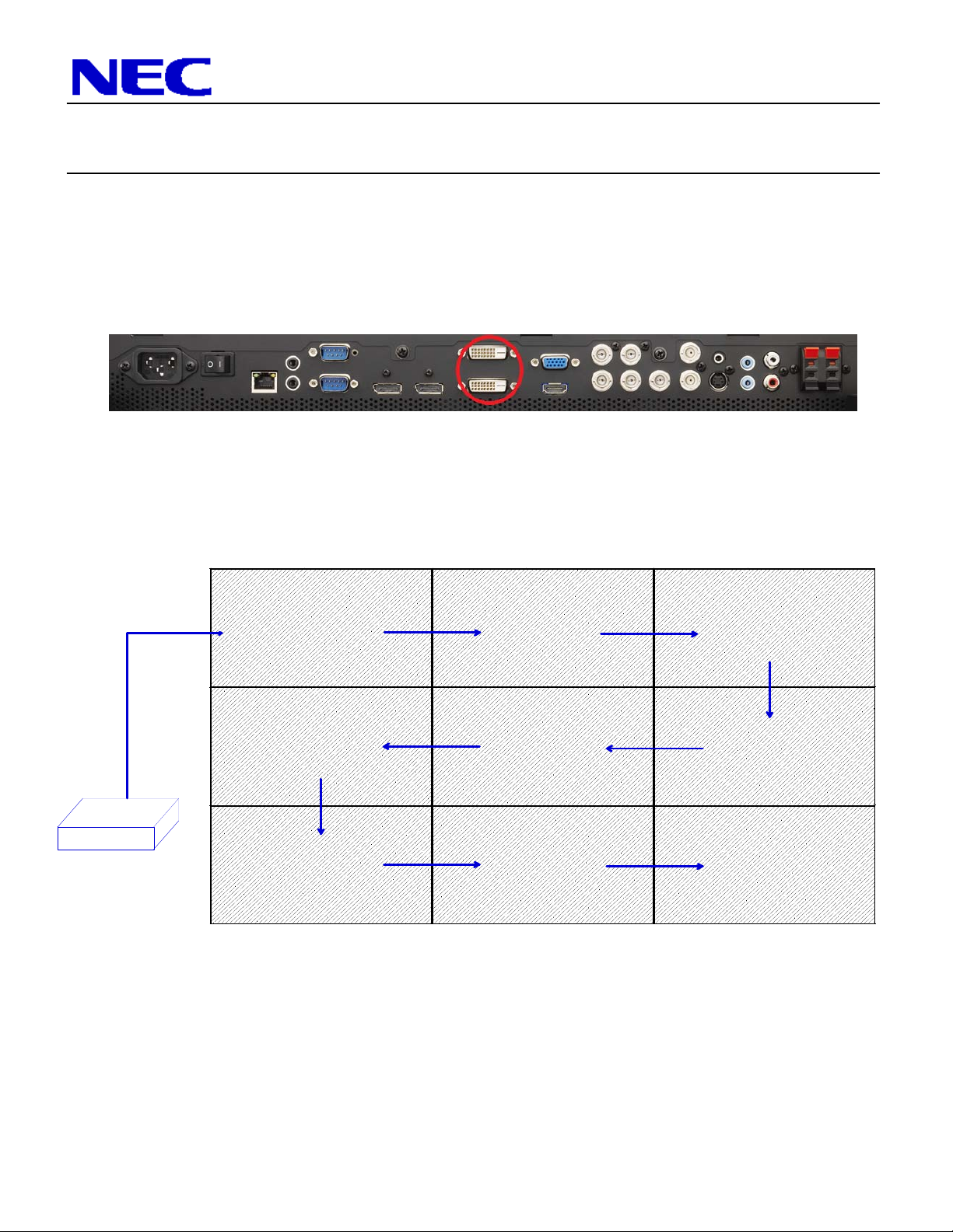
2. Connect the NEC displays using the included DVI cables and the integrated DVI
loopthrough connections on the bottom of each monitor. Note that the DVI connection
closest to the front of the display is the ‘in’ connection while the connection closest to the
wall is the ‘out’ connection.
The ideal cabling set up is shown below to match the ideal monitor ID configuration.
However, DVI daisy chaining can be done different ways and still yield the same results.
Note that the connections for each X463UN monitor are on the bottom of each display, not
the side as shown in the image below. It may be helpful to start wiring before mounting.
SOURCE
3. Connect the null modem cabling to each display. It is recommended to connect from
DVI
DVI
DVI
DVI
DVI
DVI
DVI
DVI
DVI
Display 1 to Display 2, from Display 2 to Display 3, and from Display 3 to Display 4, etc.
Note that the null modem cable needed to run from the source computer to Display 1 is not
included in this bundle. This will need to be purchased separately to control the display
remotely over RS232. Also, daisy chain the included 3.5mm mini-jack cables in the IR In
and Out of the wall
2
Page 3

NEC Display Solutions of America, Inc.
QIG-TMX9P-46UN
X463UN-TMX9P Rev 1.0
IR Out
4. Apply the OverFrame bezel kit to the video wall. Please follow instructions provided with kit
(KT-46UN-OF2).
5. Screw the IR Receiver (KT-RC) directly to the outside of the video wall and plug it directly
into the IR In terminal of Display 1.
6. Set each monitor ID up individually through the ‘MULTI-DSP’ menu within the OSD. It’s
recommended that the ID’s go from left to right, with the ID No. 1 being in the top left corner.
IR In
RS232 Out
RS232 In
Overframe Kit
3
Page 4

NEC Display Solutions of America, Inc.
QIG-TMX9P-46UN
X463UN-TMX9P Rev 1.0
Note that after the ID’s are set, there are two different ways to communicate to each screen
via the IR Remote. If the setting for the ‘IR Control’ within the ‘MULTI-DSP’ menu is set to
‘Normal’, then the IR remote control cabling is being utilized for communication. In order to
communicate to each screen individually, hold down the ‘Remote ID Set’ button on the
remote control, tap the number of the ID that you want to communicate with, then release
the Remote ID Set button. To test if this was done correctly, press the MENU button and
the OSD should now only appear on the display in which the remote control is
corresponding to. Also, more information on this is located within the User’s Manual.
To communicate to each display over the RS232 connection, make sure that the first display
(monitor ID 1) has its IR control set to ‘Primary’, while all others are set to ‘Secondary’.
When this is set, press the ‘Display’ button and the Monitor ID and Target ID should come
up in the left corner of each screen. If this is not working correctly, check your cable
connections, monitor ID’s and Primary/Secondary IR control classifications. Use the [+] and
[-] buttons on the remote to change the Target ID to the desired display you wish to
communicate with then press ‘Display’ again. If the menu is then pressed, the OSD menu
should appear on the screen of the desired ID.
7. Use the TileMatrix feature to setup the 3x3 Video Wall. The Tilematrix feature of the NEC
Display allows for one image to be expanded and displayed over a 2x3 Video Wall Setup.*
This is accessed through the OSD (On-Screen Display) Controls under the “MULTI-DSP”
4
Page 5

NEC Display Solutions of America, Inc.
QIG-TMX9P-46UN
X463UN-TMX9P Rev 1.0
main menu icon. Under the TileMatrix sub-menu, enable the feature and set the necessary
parameters that match the 3x3 Video Wall setup. Note that this step will need to be
completed for each screen.
8. Select if TileComp is necessary for this application or not. TileComp works in tandem with
TileMatrix to compensate for the width of the tiled bezels in order to accurately display the
image. Click ‘YES’ on enable to display video wall. Note that this step will need to be
completed for each screen.
If you are experiencing issues with this setup, please call our Technical Support number at
(800) 632-4662
5
 Loading...