

Page 1
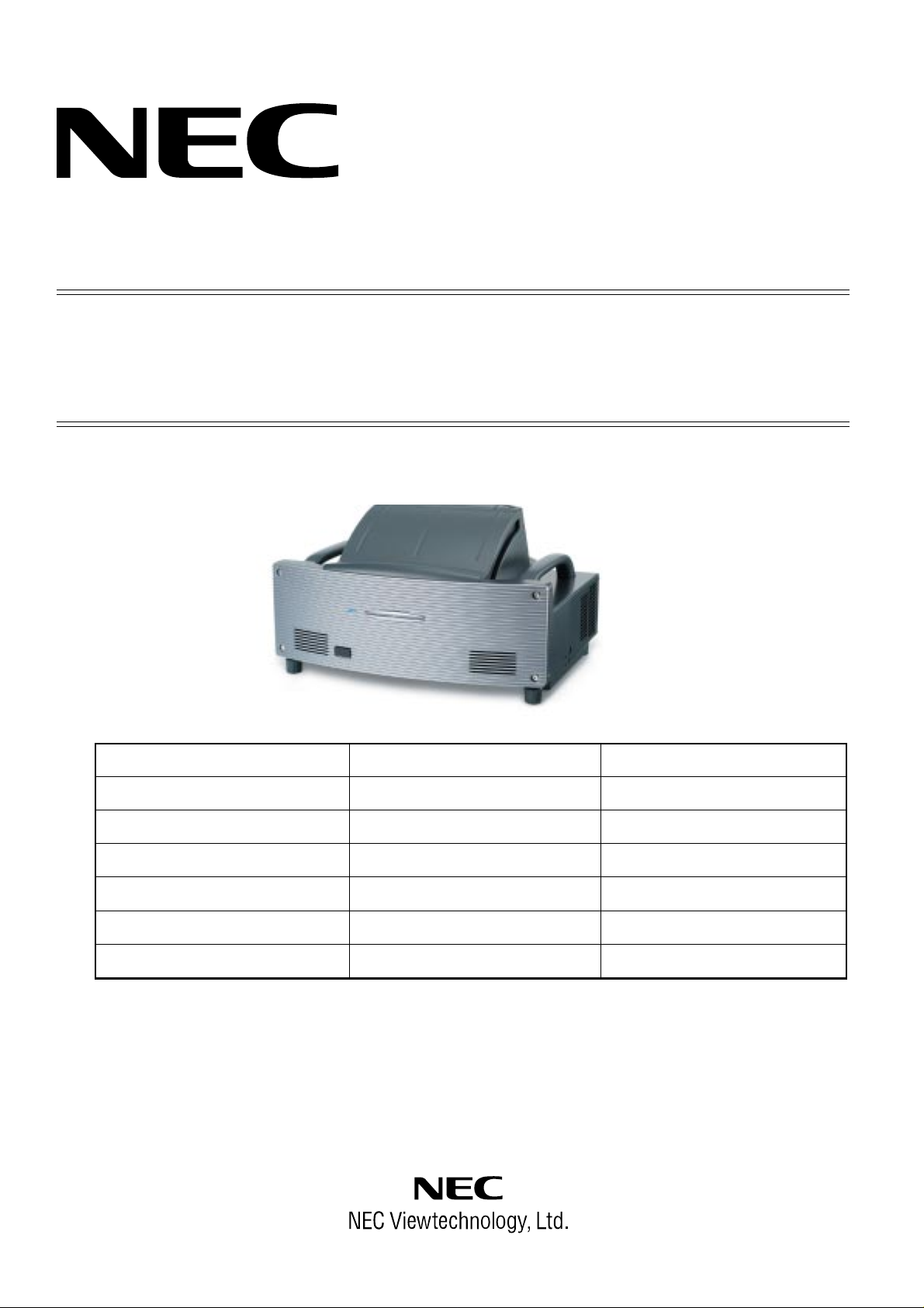
DLP Projector
MODEL WT610
WT615
WT610G
WT615G
WT610J
WT615J
(Japanese model)
(Japanese model)
SERVICE MANUAL
Better Service
PART No.3N9911112
Better Reputation
Better Profit
Copyright 1. Contens 2. Safety precautions
3. Users manual 4. Troubleshooting 5. Method of adjustments
6. Serviceman mode 7. Cleaning 8.Circuit description
9.Method of disassembly 10. Disassembly 11.Assembly diagram
12. Packaging 13. Replacement part list 14. Connection diagrams
15. Block diagrams 16. Pwb photos 17. Schematic diagrams
Back cover
SAFETY CAUTION:
Before servicing this chassis, it is important that the service
technician read and follow the “Safety Precautions” and “Product
Safety Notice” in this Service Manual.
WARNING:
SHOCK HAZARD - Use an isolation transformer when servicing.
Page 2

(1) Copyright (C) 2005, NEC Viewtechnology, Ltd.
All Rights Reserved
This document contains confidential information.
Unauthorized copying, duplication, distribution, or
republication is strictly prohibited.
(2) The contents of this manual are subject to change
without prior notice.
Page 3

Cautions needed before the start of WT610/WT615 service
1. How to turn on the power supply with the top cover assy left removed
This model is provided with an additional mode where the power supply is turned on even after the M3 cover and
the connectors have been removed for servicing.
The method of entering the mode is as shown below.
1-1. Short-circuit the test pins of SUB PWB (TP601 and TP602) with a crocodile clip or the like.
1-2. In the Normal state, keep pressing the main unit key Focus+ for more than 10 seconds.
This method is effective in the Normal state or when the power supply is turned ON. In the Power-saving state
or when the AC source is OFF, this action results in the withdrawal from this moel. Therefore, if any examination
is needed, a proper measure has to be taken not to assume the standby state.
(As a proposed method, for example, the Normal state may be fixed based on the menu or a wired remote
control may be used.)
• Normal mode ............................ Power indicator: Orange light/Status indicator: Green light.
• Power-saving mode .................. Power indicator: Orange light/Status indicator: Off.
2. The components of the FIXED MIRROR (PA41) specified below are replaceable.
FIXED MIRROR M3 (PA27) (12JS6721)
FIXED MIRROR M4 (PA27) (12JS6731)
MIRROR COVER F (PA41) (24FT9491)
MIRROR COVER R (PA41) (24FT9501)
Components cannot be replaced for those other than the 4 items specified above.
Replacement is possible only for the BASE ENGINE SASSY (82K15111).
(The junction adjustment for the optical system is possible only in the manufacturer’s factory. This action cannot
be taken at the service sector.)
Similarly, the replacement of the DMD Chip is impossible. Therefore, this replacement is possible by replacing
the Base Engine SASSY (82K15111).
Page 4

CONTENTS
SAFETY PRECAUTIONS................................................................................................. E-1
SETUP GUIDE.................................................................................................................. 2-1
USERS MANUAL ............................................................................................................. 3-1
TROUBLESHOOTING...................................................................................................... 4-1
1. Operation check................................................................................................................................... 4-1
2. MAIN PWB & SUB PWB troubleshooting ............................................................................................ 4-2
3. FMT PWB Troubleshooting.................................................................................................................. 4-4
METHOD OF ADJUSTMENTS (PC Control Software) .................................................. 5-1
CONTENTS ............................................................................................................................................. 5-1
1. Outline software descriptions............................................................................................................... 5-3
2. Equipment and operating environment ................................................................................................ 5-3
3. Aut-adjust of Sub-Brightness/Sub-Contrast software installation procedures ..................................... 5-4
3-1. Installation................................................................................................................................... 5-4
3-2. Personal computer setting ........................................................................................................... 5-12
For Win95/98/ME..................................................................................................................... 5-12
For Win2000 ............................................................................................................................ 5-14
For WinXP ............................................................................................................................... 5-17
4. Repair and adjustment procedures...................................................................................................... 5-20
4-1. Replacement of the MAIN PWB .................................................................................................. 5-20
4-2. Replacement of the SUB PWB .................................................................................................... 5-22
4-3. Replacement of the FMT PWB .................................................................................................... 5-22
4-4. Repair and replacement of the Optical Engine Unit..................................................................... 5-22
5. Various functional descriptions ............................................................................................................ 5-26
5-1. Data ............................................................................................................................................. 5-26
5-2. Sub-B/C ....................................................................................................................................... 5-28
5-3. CW Index ..................................................................................................................................... 5-30
5-4. Lamp............................................................................................................................................ 5-31
5-5. Option .......................................................................................................................................... 5-33
5-6. Auto-adjust position change ........................................................................................................ 5-34
6. Error messages.................................................................................................................................... 5-36
SERVICEMAN MODE ...................................................................................................... 6-1
CLEANING ....................................................................................................................... 7-1
CIRCUIT DESCRIPTION .................................................................................................. 8-1
MAIN PWB and SUB PWB Blocks........................................................................................................... 8-1
1. Input videosignal processing.......................................................................................................... 8-1
2. RGB output circuit........................................................................................................................... 8-1
3. Digital video signal processing........................................................................................................ 8-1
4. Sync signal processing and timing signal processing..................................................................... 8-2
5. Audio signal processing .................................................................................................................. 8-2
6. System control ................................................................................................................................ 8-2
7. Power circuit ................................................................................................................................... 8-2
8. Sefety design .................................................................................................................................. 8-2
9. Installation nature inprovement function ......................................................................................... 8-3
10. Electonic pen function (for WT615 only) ....................................................................................... 8-3
FMT PWB Block....................................................................................................................................... 8-4
1. Main board I/F................................................................................................................................. 8-4
2. LVDS conversion (Serial-parallel conversion) ................................................................................ 8-4
3. Digital signal processing ................................................................................................................. 8-4
Page 5

4. Flash ROM I/F................................................................................................................................. 8-4
5. RDRAM (RAM bus) I/F ................................................................................................................... 8-4
6. Motor driver..................................................................................................................................... 8-4
7. DMD reset circuit ............................................................................................................................ 8-4
8. Power circuit ................................................................................................................................... 8-4
METHOD OF DISASSEMBLY.......................................................................................... 9-1
DISASSEMBLY ................................................................................................................ 10-1
ASSEMBLYING DIAGRAM.............................................................................................. 11-1
PACKAGING .................................................................................................................... 12-1
1. WT610 series....................................................................................................................................... 12-1
2. WT615 series....................................................................................................................................... 12-4
REPLACMENT PART LIST.............................................................................................. 13-1
1. WT610 series....................................................................................................................................... 13-1
2. WT615 series....................................................................................................................................... 13-7
CONNECTION DIAGRAMS ............................................................................................. 14-1
BLOCK DIAGRAMS......................................................................................................... 15-1
MAIN PWB/SUB PWB ............................................................................................................................. 15-1
FMT PWB ................................................................................................................................................ 15-2
PWB PHOTOS.................................................................................................................. 16-1
MAIN PWB ASSY and SUB PWB ASSY ................................................................................................. 16-1
FMT PWB ASSY, POWER SUPPLY (DC), POWER SUPPLY (BALLAST) ............................................ 16-2
PEN PWB ASSY, KEY PWB ASSY, SENSOR TR PWB ASSY, SENSOR RE PWB ASSY ................... 16-3
REM-R PWB ASSY, COVER PWB ASSY, TEMP PWB ASSY, REM-F PWB ASSY.............................. 16-3
SCHEMATIC DIAGRAMS ................................................................................................ 17-1
MAIN PWB............................................................................................................................................... 17-1
SUB PWB (For 1st revision) .................................................................................................................... 17-11
CWC PWB ............................................................................................................................................... 17-17
KEY/LED PWB......................................................................................................................................... 17-18
COVER PWB ........................................................................................................................................... 17-19
REM-F PWB ............................................................................................................................................ 17-20
REM-R PWB ............................................................................................................................................ 17-21
SENSOR_RE PWB.................................................................................................................................. 17-22
SENSOR_TR PWB.................................................................................................................................. 17-23
TEMP PWB.............................................................................................................................................. 17-24
PEN PWB ................................................................................................................................................ 17-25
FMT PWB ................................................................................................................................................ 17-26
Page 6
SAFETY PRECAUTIONS
CAUTION
RISK OF ELECTRIC SHOCK
DO NOT OPEN
CAUTION: TO REDUCE THE RISK OF ELECTRIC SHOCK, DO NOT REMOVE
COVER. NO USER-SERVICEABLE PARTS INSIDE. REFER SERVICING
TO QUALIFIED SERVICE PERSONNEL.
This symbol warns the user that uninsulated voltage within the unit may
have sufficient magnitude to cause electric shock. Therefore, it is dangerous
to make any kind of contact with any part inside of this unit.
This symbol alerts the user that important literature concerning the
operation and maintenance of this unit has been included.
Therefore, it should be read carefully in order to avoid any problems.
ATTENTION
RISQUE D'ELECTROCUTION
NE PAS OUVRIR
MISE EN GARDE: AFIN DE REDUIRE LES RISQUES D' ELECTROCUTION, NE PAS
DEPOSER LE COUVERCLE, IL N'Y A AUCUNE PIECE
UTILISABLE A L'INTERIEUR DE CET APPAREIL. NE CONFIER
LES TRAVAUX D'ENTRETIEN QU'A UN PERSONNEL QUALIFIE.
Ce symbole a pour but de prévenir I' utilisateur de la présence d'
une tension dangereuse, non isolée se trouvant à l' intérieur de l'
appareil. Elle est d' une intensité suffisante pour constituer un risque
d' électrocution. Eviter le contact avec les pièces à l' intérieur de
cet appareil.
Ce symbole a pour but de prévenir l' utilisateur de la présence d'
importantes instructions concernant l' entretien et le fonctionnement
de cet appareil. Par conséquent, elles doivent être lues
attentivement afin d' éviter des problèmes.
WARNING
HEATSINK MAY BE ENERGIZED.
TEST BEFORE TOUCHING.
Heat sink located on the power board, is electrified.
mark is putted on the primary heat sink.
Pay attention to this area.
2-1
Page 7

SAFETY PRECAUTIONS
During servicing carefully observe the following.
1. OBSERVE ALL PRECAUTIONS
Items and locations that require special care during servicing, such as the cabinet, chassis, and parts are labelled
with individual safety instructions. Carefully comply with
these instructions and all precautions in the instruction
manual.
2. BE CAREFUL OF ELECTRIC SHOCK
The chassis carries an AC voltage. If you touch the
chassis while it is still alive, you will get a severe shock.
If you think the chassis is alive, use an isolating
transformer or gloves, or pull out the plug before
replacing any parts.
3. USE SPECIFIED PARTS
The components have been chosen for minimum
flammability and for specific levels of resistance value
and withstand voltage. Replacement parts must match
these original specifications. Parts whose specifications
are particularly vital to safe use and maintenance of the
set are marked on the circuit diagrams and parts list.
Substitution of these parts can be dangerous for you
and the customer, so use only specified parts.
4. REMOUNT ALL PARTS AND RECONNECT ALL
WIRES AS ORIGINALLY INSTALLED
For safety, insulating tape and tubes are used
throughout, but some lift-off parts on the printed wiring
board require special attention.
All wires are positioned away from high-temperature and
high-voltage parts, and, if removed for servicing, they
must be retuned precisely to their original positions.
5. LAMP
Be very careful of the lamp because it generates high
heat while it is used at high voltage. When replacing
the bulb, make sure it is cool enough.
6. MIRROR
Do not look into the mirror during projection. This
important to avoid damage to the eyes.
7. SERVICING
At the time of repair or inspection services, use an earth
band (wrist band), without fail.
8. RUN A COMPLETE SAFETY CHECK AT THE
COMPLETION OF SERVICING
After completion of servicing, confirm that all screws,
parts, and wiring, removed or disconnected for servicing,
have been returned to their original positions. Also
examine if the serviced sections and peripheral areas
have suffered from any deterioration as a result of
servicing. In addition, check insulation between external
metallic parts and blades of wall-outlet plugs. This
examination is indispensable in confirming complete
establishment of safety.
(Insulation check)
Pull out a plug from a wall outlet to disconnect the
connection cable. Then turn on the POWER switch.
Use a 500V megger (Note 2) and confirm that the
insulation resistance is 1MΩ or more between each
terminal of the plug and exposed external metal (Note
1). If the measured value is below the specified level,
then it is necessary to inspect and fix the set.
(Note 1)
Exposed external metal....RGB input terminals, control
terminals, etc.
(Note 2)
If a 500V megger is not available for an unavoidable
reason, then use a circuit tester or the like for inspection.
2-2
Page 8
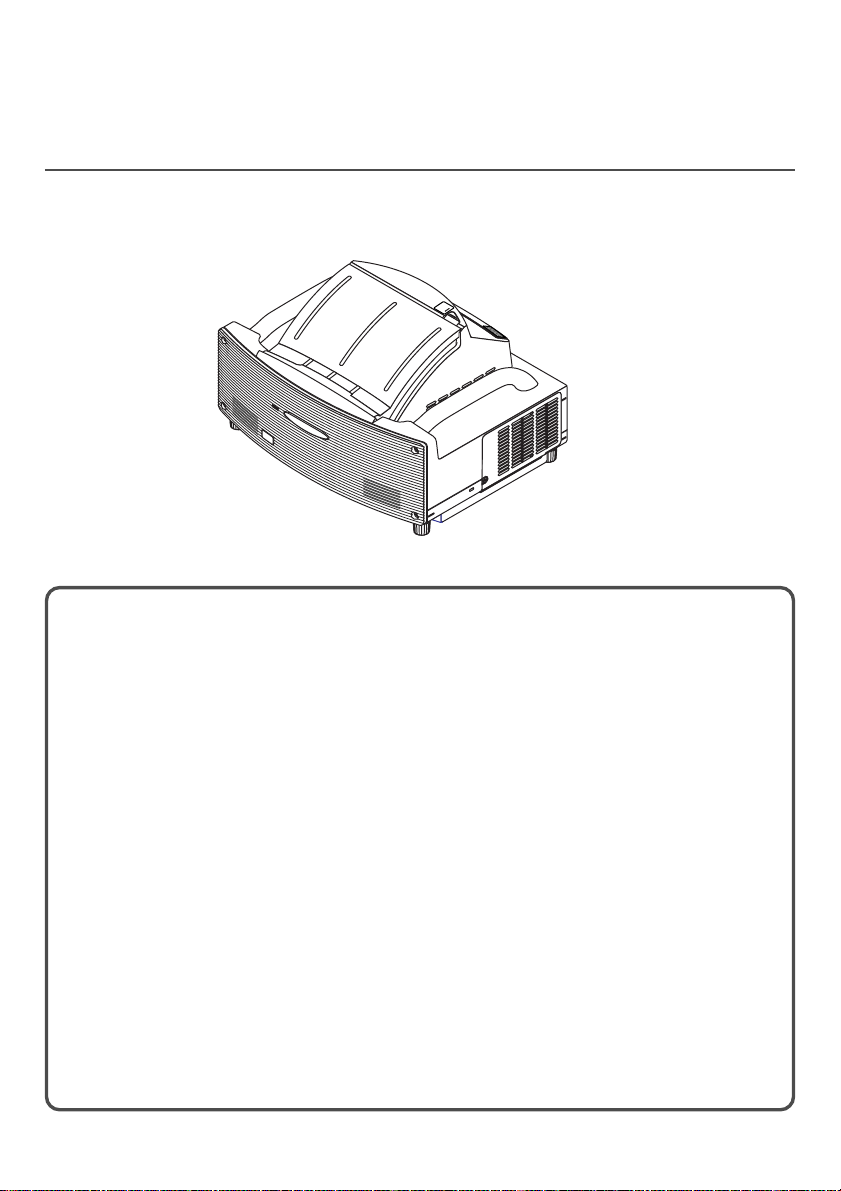
WT615/WT610 SETUP GUIDE
U
NLOCK
M
IRROR
LOCK
Contents
WARNING
Part Names of the Projector ........................................................................ E-1
Setting Up the Screen and Projector ......................................................E-2
Connections............................................................................................ E-5
Opening the Mirror Cover .......................................................................E-5
Tur ning on the Projector .......................................................................... E-6
Adjusting the Position and Size of the Projected Image
(Focus Adjustments)........................................................................... E-8
Selecting a Source ............................................................................... E-13
Optimizing an RGB Image Automatically.............................................. E-14
Adjusting Pincushion or Barrel Distortion (Pincushion) ........................ E-15
Using the Laser Pointer ........................................................................E-17
Using the Electronic Pen (WT615 only)................................................E-18
Tur ning off the Projector ........................................................................ E-21
After Use...............................................................................................E-22
Page 9

Scope of this Guide
The subject of this guide is to describe the procedure for adjusting the image projected
from the WT615/WT610 to the desired screen size. Descriptions of screens and stands
for use with the WT615/WT610 are also provided.
Please see the user's manual for information regarding the detailed operation of the
WT615/WT610 (hereafter referred to as "the unit" or "the projector").
NOTE
(1) The contents of this guide may not be reprinted in part or whole without permission.
(2) The contents of this guide are subject to change without notice.
(3) Great care has been taken in the creation of this guide; however, should any questionable points,
errors, or omissions be apparent, please contact us.
(4) Notwithstanding Section (3), this company will not be responsible for any claims of loss or profit or
other matters deemed to be the result of using this unit.
(5) Guides with incorrect collating or missing pages will be replaced.
(6) When differences arise between this guide and the user's manual, this guide will be given priority.
Page 10

WARNING
• Do not set up the projector, the screen or stand in a place that is not level or in an
unstable location. Doing so may result in the screen falling over or the projector falling
which may result in injury.
• When setting up the projector on the stand, first secure the top plate in a level condi-
tion. When the top plate is set at an angle, the projector may fall resulting in injury.
• Use a stand that can fully support the weight of the projector (which for this unit is
approximately 14.1 lbs/6.4 kg). Failing to do so may result in the projector falling and
causing injury.
Page 11
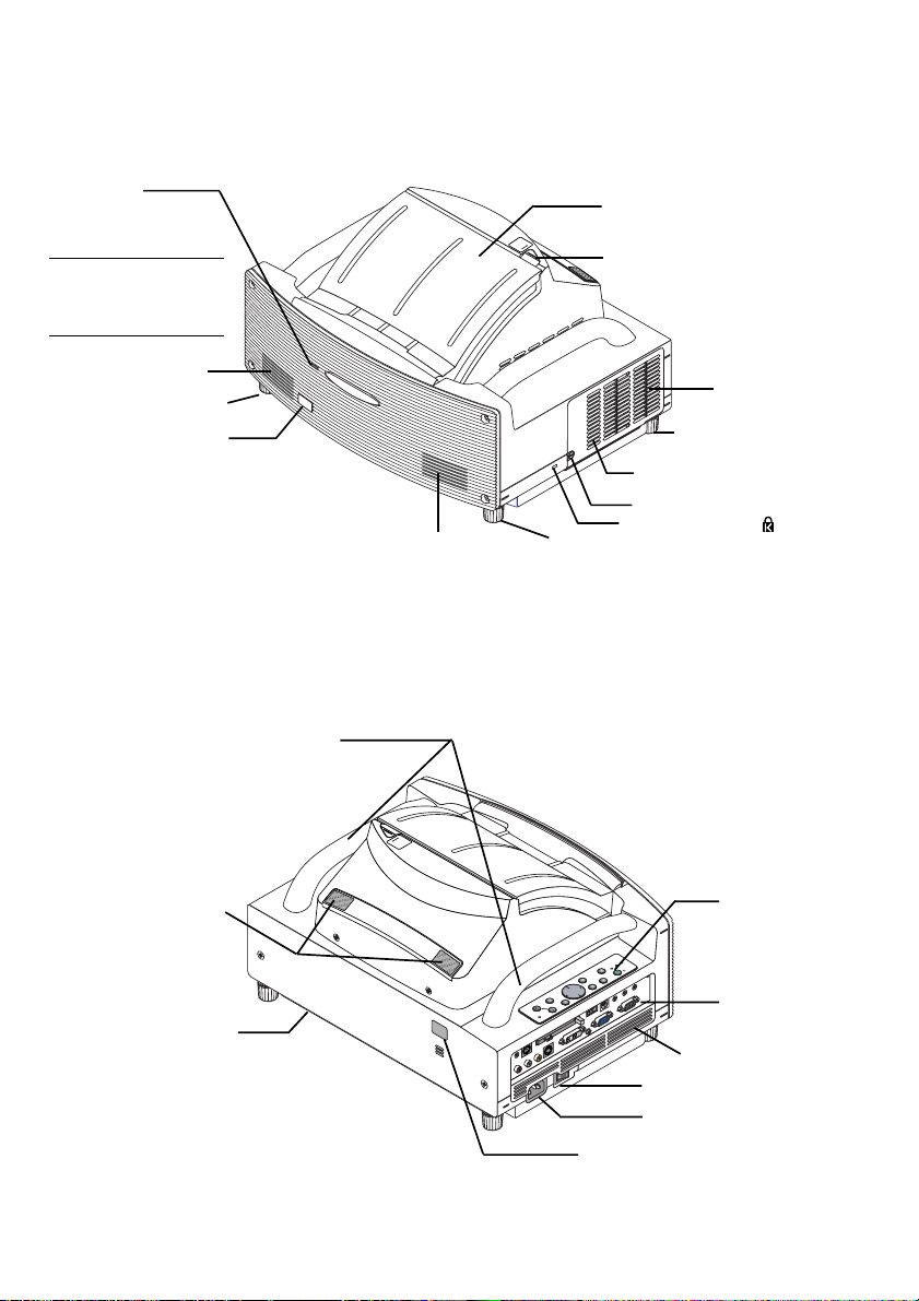
Part Names of the Projector
PC CARD
R-AUDIO IN-L/MONO
VIDEO IN
S-VIDEO IN
DVI-I IN
DVI-I
AUDIO IN
AUDIO OUT
PCCONTROL
REM
OTE
IN
COMPUTER IN
MONITOR OUT
COMPUTER
USB
Front indicator
Lights blue to indicate that
the projector is turned on
or in the Standby mode.
NOTE: When [Standby Mode]
UN
M
LO
IR
C
R
K
O
R
LO
C
K
Mirror cover (E-5)
Mirror cover lock switch
is set to “Power-saving”, this
indicator lights blue only with
power on.
Speaker
Foot
Remote sensor
Ventilation (outlet)
Foot
Lamp cover
Lamp cover screw
Speaker
Foot
Built-in Security Slot ( )*
* This security slot supports the MicroSaver® Security System. MicroSaver® is a registered trademark of
Kensington Microware Inc. The logo is trademarked and owned by Kensington Microware Inc.
Carrying handle
Sensor for Electronic pen
(WT615 only)
Ventilation (outlet)
CK
LO
R
MIRRO
UNLOCK
Controls (E-6)
P
M
S
A
U
L
T
A
T
R
S
E
W
Y
O
B
P
D
/
N
N
A
O
T
S
M
R
O
F
D
T
E
3
S
R
U
O
J
IT
T
X
D
U
E
A
A
R
E
E
T
N
E
T
C
E
L
E
S
E
C
R
U
U
O
N
S
E
M
S
D
U
R
C
A
O
C
F
C
P
Te r minal panel (E-5)
Ventilation (inlet)
Main Power Switch (E-6)
AC Input (E-5)
Remote sensor
E-1
Page 12
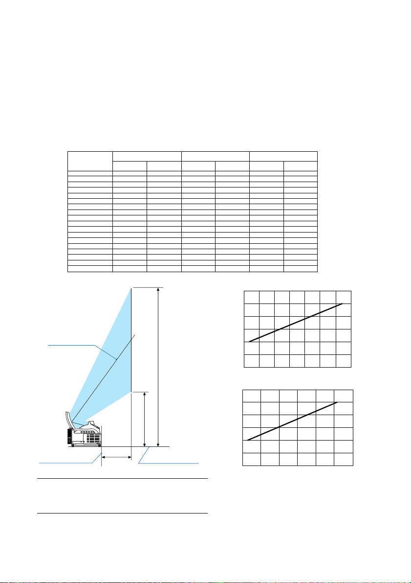
Setting Up the Screen and the Projector
1. Refer to "Throw Distance (C)" in the diagram and use a distance between the screen and projector that corresponds to the screen size.
As an example, when projecting to a 60" screen, set the projector with a separation of approximately 10.4"/26.3
cm from the screen.
2. Refer to "Height (D)" below and adjust the screen height, or adjust the height of the projector stand.
As an example, when projecting to a 60" screen, adjust the height from the feet of the projector to the lower
edge of the screen to approximately 19.0"/48.2 cm.
Screen size
(inch)
40
45
50
55
60
65
67
70
72
75
78
80
84
85
90
95
96
100
Height (B)
mm inch
659
729
799
869
939
1010
1037
1080
1107
1149
1191
1219
1275
1289
1359
1428
1443
1499
25.9
28.7
31.5
34.2
37.0
39.7
40.8
42.5
43.6
45.2
46.9
48.0
50.2
50.7
53.5
56.2
56.8
59.0
Throw distance (C)
mm inch
114
164
214
263
313
332
362
381
412
441
461
500
510
559
609
619
659
Screen center
B
D
Back of projector
C
Projector foot
NOTE
• There is a tolerance of +/–5% because of design values.
• The projection distance and the lower edge of the screen
are calculated using a 4:3 aspect ratio.
Height (D)
mm inch
64
10.4
12.3
13.1
14.3
15.0
16.2
17.4
18.1
19.7
20.1
22.0
24.0
24.4
25.9
2.5
4.5
6.4
8.4
Screen size (inch)
354
386
418
450
482
514
526
546
558
577
596
609
635
641
673
704
711
737
120
100
80
60
40
20
0
0 100 200 300 400 500 600 700
13.9
15.2
16.5
17.7
19.0
20.2
20.7
21.5
22.0
22.7
23.5
24.0
25.0
25.2
26.5
27.7
28.0
29.0
Throw distance C (mm)
120
100
80
60
40
Screen size (inch)
20
0
051015 20 25 30
Throw distance C (inch)
E-2
Page 13
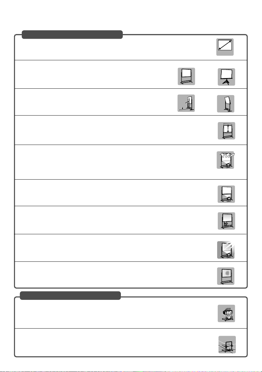
Screens Suited
• The projector can accommdate screen sizes from 40” (81.3 cm/32.0” W ⳯ 61.0 cm/24.0” H)
to 100 inch (203.2 cm/80.0” W ⳯ 152.4 cm/60.0” H).
40"-100"
• Use a panel or tension type screen that has a flat surface.
Recommended
Do not use roll type screens and other screens that bend or form a wavy
surface easily. Doing so will result in increased distortion of the projected
image.
• View the screen directly from the side so that it is perfectly vertical.
Recommended
A slanted screen will result in increased keystone distortion.
90˚
• In using this projector, increasing the screen size will move the projection position upward. To
accommodate this, please use a screen that can be raised and lowered to a given screen
position. See page E-2 for information about the positioning relationships between the screen
and this projector.
• High gain type screens are not optimal for use with this projector. The lower the screen gain
(i.e., screen gain on the order of 1), the better the appearance of the projected image.
For more information about screen gain, consult catalogs from screen manufacturers.
• Screen frames or pen shelves that protrude from the front of the screen surface may block
some of the light from the projector.
• Due to the projection angle of the projector, many standard rear projection screens may produce uneven brightness, hot spotting or not produce maximum brightness to the viewer. For
more details utilizing rear projection screens and their applications with this projector, please
contact your NEC dealer.
• Controlled ambient light environments will allow for an image of higher contrast and depth to
be displayed.
Not recommended
Not recommended
Recommended
Not recommended
Not recommended
Not optimal
Not recommended
• Screens with a soiled, scratched, or discolored area will not produce a clean image. Care
should be used in the handling of the screen.
Stands Suited
• In using this projector, increasing the screen size will move the projection position upward. To
accommodate this, please use a stand that has a height positioning adjustment. See page E2 for information about the positioning relationships between the screen and this projector.
• Use a stand that will allow this projector to be set up in a level condition. Adjust the feet of the
stand to make sure it is level.
E-3
Not recommended
Recommended
Recommended
Level
Page 14

Ambient environmental condition
• Do not place the screen near vents.
Air movement hitting the screen, causing the projected image to ripple.
• Do not illuminate the projector with strong light sources such as halogen lamp.
Doing so can cause the object detection sensor to malfunction, resulting in the projector not turning on.
Precautions for using the electronic pen (WT615 only)
• Use a hard-surface screen because you tap the screen using the electronic pen.
Keep in mind that the electronic pen tip can cause scratches on the screen surface as the pen tip is made of
hard material.
•Avoid using the electronic pen near a device such as a CRT monitor or a measuring machine. Otherwise, the
electronic pen may not work properly.
•Avoid using in a room with the ceiling and walls made of metal which is prone to reflect sound waves. Otherwise,
the electronic pen may not work properly.
•Avoid using the electronic pen in direct sunlight or near an inverter fluorescent lamp. If strong light falls on the
sensor for electronic pen, the electronic pen will not respond.
•Avoid using the electronic pen near an air conditioner. Otherwise the electronic pen may not work properly.
• Requirements for the Electronic Pen
- Screen size: 40” to 80”
- Projector orientation: “Desktop Front” and “Ceiling Front”
- Screen type: “4:3”
- Aspect ratio: “4:3”
- Digital Zoom: “Horizontal Position” is set to 0 and “Vertical Position” is set to 0
- No correction has been made for [Pincushion], [Cornerstone] and [Keystone].
- Operating temperature: 59 to 95°F (15 to 35°C)
E-4
Page 15
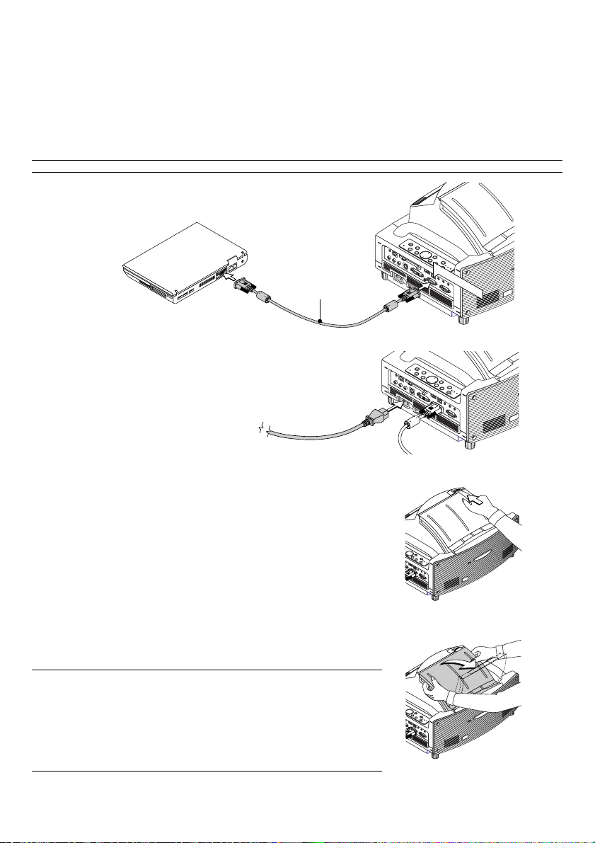
Connections
PC
C
AR
D
A
UD
IO
IN
R
L
/M
O
N
O
V
ID
EO IN
S
-V
IDE
O
IN
D
V
I-
I IN
C
O
M
PU
TE
R
IN
M
O
NITO
R
O
U
T
D
VI-I CO
M
PU
TE
R
AUD
IO IN
U
S
BA
UD
IO O
UT
PCCO
N
TR
OL
RE
M
OT
E
IN
P
C
C
A
R
D
A
U
D
I
O
I
N
R
L
/M
O
N
O
V
I
D
E
O
I
N
S
V
I
D
E
O
IN
D
V
I
-
I
I
N
C
O
M
P
U
T
E
R
I
N
M
O
N
I
T
O
R
O
U
T
D
V
I-
I
C
O
M
P
U
T
E
R
A
U
D
I
O
I
N
U
S
B
A
U
D
I
O
O
U
T
P
C
C
O
N
T
R
O
L
R
E
M
O
T
E
I
N
PO
W
E
R
E
N
TE
R
E
XIT
S
TA
TU
S
LAM
P
O
N
/
S
T
A
ND
BY
A
UT
O
A
D
JU
S
T
3D
R
E
F
OR
M
S
EL
E
C
T
U
N
LO
C
K
M
IR
R
O
R
L
O
C
K
C
O
M
P
U
T
E
R
I
N
M
O
N
I
T
O
R
O
U
T
D
V
I
-
I
C
O
M
P
U
T
E
R
A
U
D
I
O
I
N
U
S
B
A
U
D
I
O
O
U
T
C
O
M
P
U
T
E
R
IN
M
O
N
IT
O
R
O
U
T
D
V
I-I
C
O
M
P
U
T
E
R
A
U
D
IO
IN
U
S
B
A
U
D
I
O
O
U
T
1. Connect the supplied 15pin-15pin signal cable.
For older Macintosh computers, use a commercially available pin adapter to connect to your Macintosh’s
video port.
NOTE : Power down all equipment before making connections.
D
R
A
C
C
P
E
C
R
U
S
O
U
S
C
O
F
U
N
E
M
T
C
E
L
E
S
T
I
X
E
M
D
R
3
R
O
F
E
T
E
N
R
E
R
E
W
O
S
T
O
T
U
S
P
U
T
U
A
J
A
T
D
S
A
P
M
A
L
/
Y
N
B
O
D
N
COMPUTER IN
A
T
RGB/VGA signal
cable (supplied)
2. Connect the supplied power cable.
Opening the Mirror
1. Slide the mirror cover lock switch to the unlock position.
S
D
R
A
C
C
P
E
C
R
U
S
O
U
S
C
O
F
U
N
E
M
T
C
E
L
E
S
IT
X
E
M
D
R
3
R
O
F
E
T
E
N
R
E
R
E
W
O
S
T
O
T
U
S
P
U
T
U
A
J
A
T
D
S
A
P
M
A
L
/
Y
N
B
O
D
N
A
T
S
K
C
O
L
N
U
R
O
K
R
C
R
I
O
L
M
2. Slowly open the mirror cover holding both ends.
NOTE:
• Do not release your hold of the mirror cover until fully open.
• Do not apply excessively strong pressure against the mirror cover or mirror
surface while opening it.
• Keep finger prints off the mirror surface. Leaving finger prints in the mirror surface
might cause an unwanted shadow and poor picture quality.
If the mirror surface is soiled with finger prints, wipe them off with the supplied
cleaning cloth. See page 130 of the user's manual.
E-5
T
C
E
L
E
S
T
I
X
E
M
D
R
3
R
O
F
E
T
E
N
R
E
R
E
W
O
S
T
O
T
U
S
P
U
T
U
A
J
A
T
D
S
A
P
M
A
L
/
Y
N
B
O
D
N
A
T
S
Page 16
POINTER
LASER
MAGNIFY
PAGE
OFF
POWER
ON
E
N
T
E
R
M
E
N
U
E
X
I
T
R
-
C
L
I
C
K
UP
DOWN
POWER
ENTER EXIT
STATUS
LAMP
ON/
STAND BY
AUTO
ADJUST
3D
REFORM
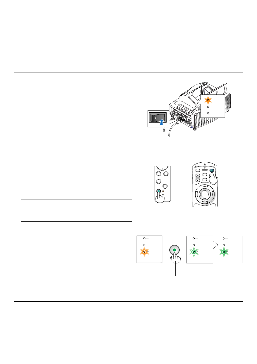
Turning on the Projector
NOTE:
• The projector has two power switches: a main power switch and a POWER (ON/STAND BY) button (POWER ON and OFF on the
remote control).
• When plugging in or unplugging the supplied power cable, make sure that the main power switch is pushed to the off (
position. Failure to do so may cause damage to the projector.
1. Open the mirror cover. See page E-5 for more
details.
2. To turn on the main power to the projector, press the
Main Power switch to the on position ( I ).
• The POWER indicator will light orange.
POWER
STATUS
LAMP
䡬
)
3. Press the POWER (ON/STAND BY) button on the
projector cabinet or POWER ON button on the
remote control for a minimum of 2 seconds, when
the PWOER indicator turns a steady green the
projector is ready to use.
• After you turn on your projector, ensure that the
computer or video source is turned on.
NOTE: If you turn on the projector immediately after the lamp
is turned off or when the temperature is high, the fans run
without displaying an image for some time and then the
projector will display the image.
NOTE: When no signal is available, a blue, black or logo screen is displayed.
E-6
Cabinet controls Remote control
ON/
Blinking for
one minute
Blinking green
Standby
LAMP
STATUS
POWER
Steady orange
light
Press this button for a
minimum of 2 seconds.
STAND BY
Power On
LAMP
STATUS
POWER POWER
light
LAMP
STATUS
Steady green
light
Page 17
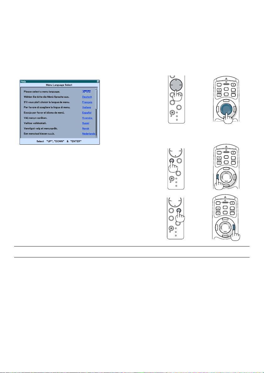
Note on Startup screen (Menu Language Select screen)
When you first turn on the projector, you will get the Startup menu. This menu gives you the opportunity to select one
of the 21 menu languages.
To select a menu language, follow these steps:
1. Use the SELECT or button to select one of the
21 languages for the menu.
2. Press the ENTER button to execute the selection.
The menu will be displayed in the language you
have selected.
Cabinet controls Remote control
OFF
ON
SELECT
ENTER EXIT
AUTO
ADJUST
ON/
STAND BY
SELECT
ENTER
AUTO
ADJUST
ON/
STAND BY
REFORM
REFORM
POWER
STATUS
LAMP
EXIT
3D
POWER
STATUS
LAMP
3D
MAGNIFY
MAGNIFY
POWER
LASER
PAGE
UP
POINTER
DOWN
N
U
E
M
E
R
X
E
I
T
T
N
E
R
K
-
C
C
I
L
OFF
ON
POWER
LASER
PAGE
UP
POINTER
DOWN
N
U
E
M
E
R
X
E
I
T
T
N
E
R
K
-
C
C
I
L
3. To close the menu, press the EXIT button.
ENTER
AUTO
ADJUST
ON/
STAND BY
SELECT
REFORM
EXIT
3D
POWER
STATUS
LAMP
OFF
MAGNIFY
R
E
T
N
ON
POWER
LASER
PAGE
UP
POINTER
DOWN
N
U
E
M
E
X
I
T
E
R
K
-
C
C
I
L
NOTE: Immediately after turning on the projector, screen flicker may occur. This is not a fault. Wait 3 to 5 minutes until the lamp
lighting is stabilized.
•When the Lamp mode is set to Eco, the Lamp indicator will light green.
• If one of the following things happens, the projector will not turn on.
- If the internal temperature of the projector is too high, the projector detects abnormal high temperature. In this
condition the projector will not turn on to protect the internal system. If this happens, wait for the projector's
internal components to cool down.
-When the lamp reaches its end of usable life, the projector will not turn on. If this happens, replace the lamp.
- If the lamp fails to light, and if the STATUS indicator flashes on and off in a cycle of six times, wait a full minute and
then turn on the power.
-When the mirror cover is closed.
- If the temperature sensor detects excessive heat in the bottom of the mirror or in the light path, the projector will
not turn on. Remove objects such as dust from the bottom of the mirror.
- The projector has a sensor which detects an object in front of the largest mirror or in the light path. If the sensor
detects any object, the projector will not turn on. Remove the object.
- Do not illuminate the projector with strong light source such as halogen lamp.
Doing so can cause the object detection sensor to malfunction, resulting in the projector not turning on.
• Immediately after turning on the projector and displaying an image, you cannot turn off the projector for 60 seconds.
E-7
Page 18
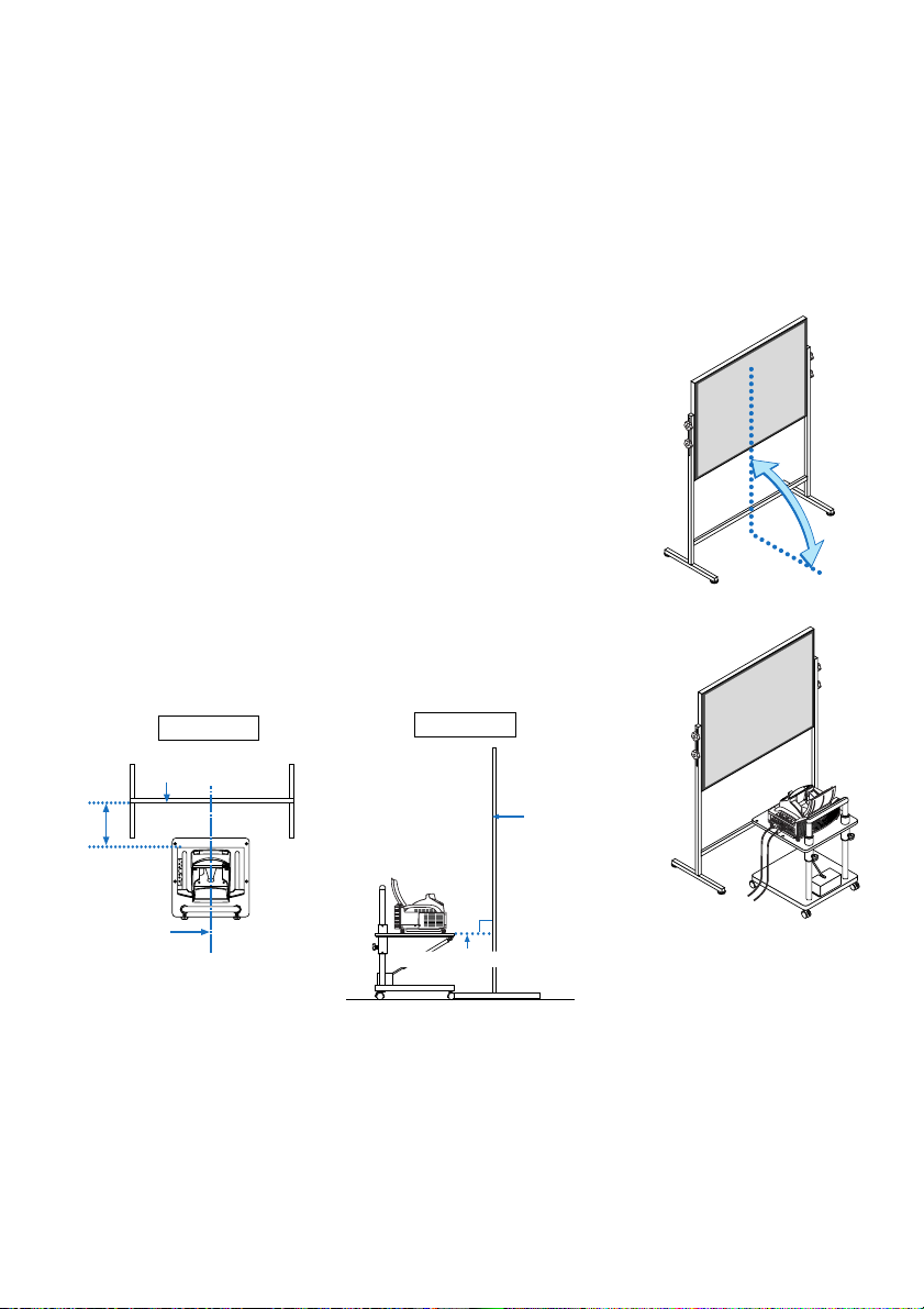
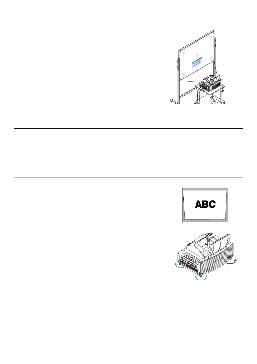
Adjusting the Position and Size of the Projected Image (Focus Adjustments)
• After turning on the power, projected images may flicker for 3 to 5 minutes until the lamp lighting is stabilized.
Also after turning on the projector, the picture position may be slightly changed.
Wait 10 minutes until the light status and projected images become stable.
• If the screen is tilted vertically or horizontally, keystone distortion becomes large. Proceed with the following
steps to correctly set up the projector and the screen.
1. Check whether the screen is set up to be vertical by viewing it from
the side.
90˚
2. Check that the projector is set to be parallel with the screen.
Parallel
Align the
projector
center with
the screen
center
Top view
Screen surface
Side view
90
°
Bottom of projector
E-8
Screen surface
Page 19
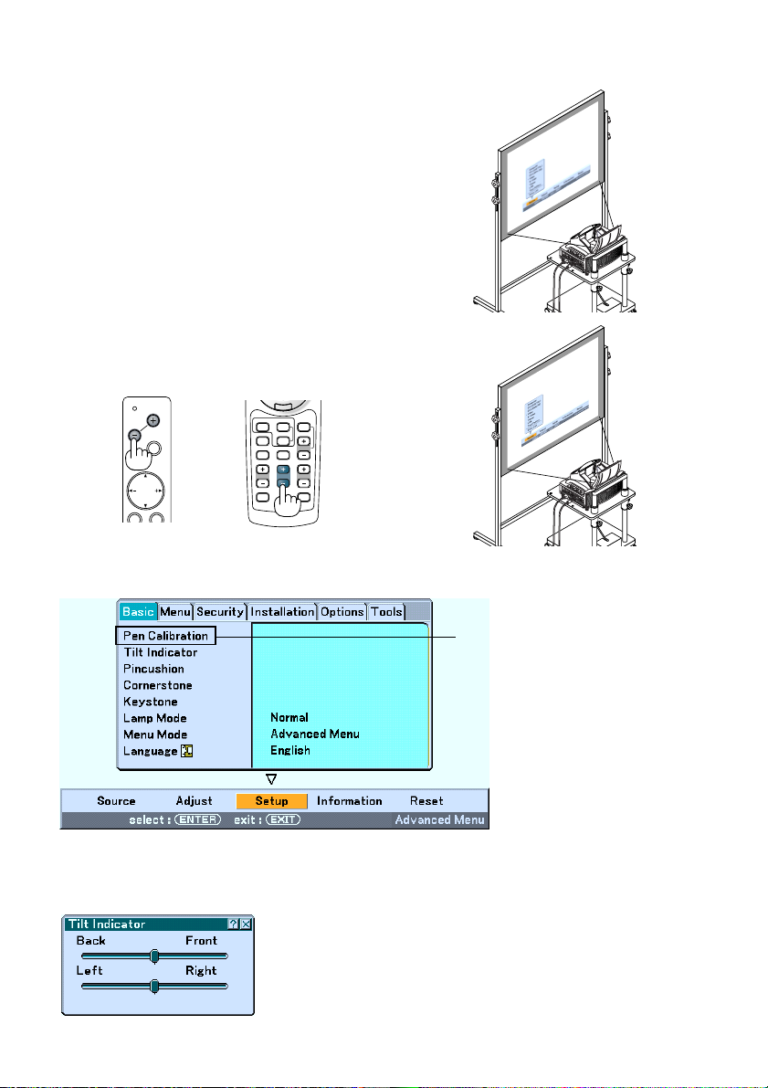
3. Press the MENU button.
The menu will be displayed.
4. Press the FOCUS +/- buttons and align the focus of the projected
image.
Cabinet controls
PC CARD
FOCUS
SOURCE
MENU
SELECT
Remote control
R
K
-
C
C
I
L
VIDEO
VIEWER
COMPUTER
AUTO ADJ.
SLIDE
ASPECT
HELP
PIC-MUTE
FOCUS
ZOOM
VOLUME
3D REFORM
FREEZE
5. Use the SELECT button to select [Setup] and then press the ENTER button.
WT615 only
6. Use the SELECT or button to select [Tilt Indicator] and then press the ENTER button.
The test pattern will be displayed to fill the screen. At the same time the [Tilt Indicator] screen will be displayed at
the bottom of the screen.
E-9
Page 20
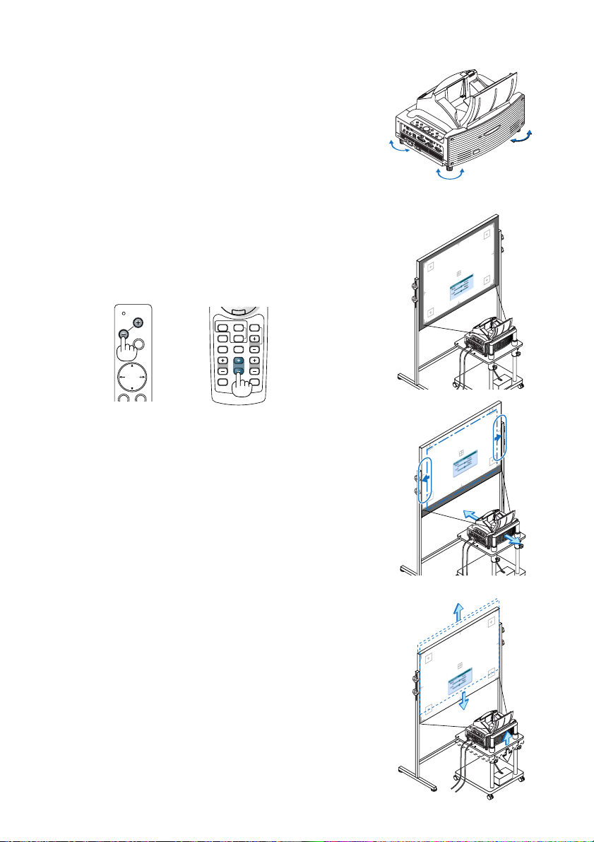
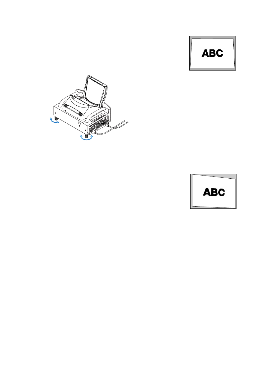
7. Adjust the height to keep the projector level by rotating the
feet on the front and the rear.
Tilting the projector will move the Tilt Indicator’s slider to the left or
right accordingly. Tilt the projector so that both of the sliders of
“Back/Front” and “Left/Right” are shown at the center. When the
slider reaches the center, it will become green.
8. Press the FOCUS +/– buttons to align the focus of the projected
image.
A press of the FOCUS +/– buttons results in focus being taken simultaneously with the adjustment of vertical keystone distortion. See page E-
11.
Cabinet controls
PC CARD
FOCUS
SOURCE
MENU
SELECT
Remote control
R
K
-
C
C
I
L
VIDEO
VIEWER
COMPUTER
AUTO ADJ.
SLIDE
ASPECT
HELP
PIC-MUTE
FOCUS
ZOOM
VOLUME
FREEZE
3D REFORM
9. Move the projector away from or closer to the screen and position it
so that the left and right sides of the projected image are aligned
with the width of the screen.
Up
Down
10. Adjust the height of the screen and the height of the stand to align
the lower edge of the projected image with the lower edge of the
screen.
E-10
Page 21
11. Press the FOCUS +/– buttons to align the focus of the projected
image again.
Repeat step 9 to 11 if the display image is not aligned with the screen.
12. To complete the adjustment, press the EXIT button three times.
The menu will disappear.
NOTE:
• In terms of the optical characteristics of this projector, in addition to keystone distortion, there may be occurrences of slight
pincushion type or barrel type distortion. See “
Adjusting Pincushion or Barrel Distortion (Pincushion)” on page E-15.
To adjust the projected image with the screen, first perform Steps 9 to 11 on pages E-10 to E-11 (Adjustment of the projection
→
distance
Height adjustment of the projected image → Focus adjustment), then align the 4 corners of the projected image
with the 4 corners of the screen. Following this, if the pincushion type or the barrel type distortion is conspicuous, please
perform "
Adjusting Pincushion or Barrel Distortion (Pincushion)" after you select a source you want to project.
• If the keystone distortion is not improved after pressing the FOCUS +/– buttons and adjusting the focus, or the aspect ratio
does not agree, make sure the screen or projector are not tilted.
[Symptom1]
In the case of keystone distortion (as illustrated), either the screen is directed
slightly upward or the projector is directed slightly upward.
[Action]
Tilt the top end of the screen to the front or rotate the front feet of the projector
to correct keystone distortion.
E-11
Up
Down
Page 22
[Symptom2]
P
C
C
A
R
D
R
-
A
U
D
I
O
I
N
-
L
/
M
O
N
O
V
I
D
E
O
I
N
S
-
V
I
D
E
O
I
N
D
V
I
-
I
I
N
D
V
I
-
I
A
U
D
I
O
I
N
A
U
D
I
O
O
U
T
P
C
C
O
N
T
R
O
L
R
E
M
O
T
E
I
N
C
O
M
P
U
T
E
R
IN
M
O
N
I
T
O
R
O
U
T
C
O
M
P
U
T
E
R
U
S
B
In the case of keystone distortion (as illustrated), either the screen is directed
slightly downward or the projector is directed slightly downward.
[Action]
Tilt the bottom end of the screen to the front or rotate the rear feet (screen side) of
the projector to correct keystone distortion.
K
C
O
L
R
O
K
R
C
R
I
O
L
M
N
U
P
M
S
A
U
L
T
A
T
R
S
E
W
Y
O
B
P
D
/
N
N
A
O
T
S
M
R
O
F
D
T
E
3
S
R
U
O
J
IT
T
X
D
U
E
A
A
R
E
T
N
E
T
C
E
L
E
S
E
C
R
U
U
O
N
S
E
M
S
D
U
R
C
A
O
C
F
C
P
Up Down
As illustrated in the diagram to the right below, when the top and bottom edges of
the image are not parallel to each other, it can be suspected that the screen and
the projector are not parallel to each other.
[Symptom 3]
As illustrated in the diagram to the right, when the left edge of the image is widened vertically, either the projector is not placed straight in front of the screen or
the projector is directed slightly to the left.
Conversely, when the right edge of the image is widened vertically, either the
projector is not placed straight in front of the screen or the projector is directed
slightly to the right.
[Action]
Place the projector straight in front of the screen.
Make sure that the screen and the projector are parallel to each other.
E-12
Page 23
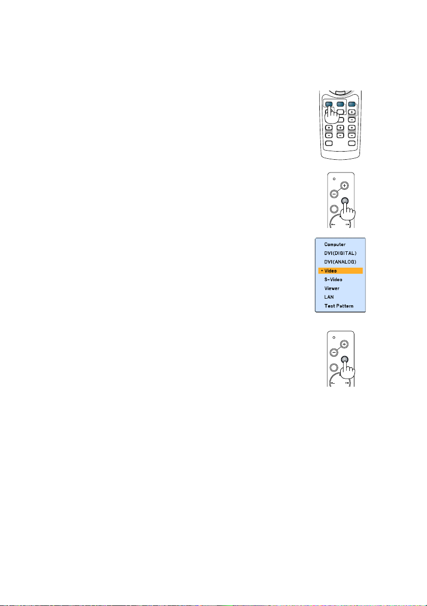
Selecting a Source
Selecting the computer or video source
Using the Remote Control
Press any one of the COMPUTER, VIDEO or VIEWER buttons.
VIDEO
VIDEO
ASPECT
PIC-MUTE
VOLUME
FREEZE
R
-
C
COMPUTER
AUTO ADJ.
HELP
K
C
I
L
VIEWER
SLIDE
ZOOMFOCUS
3D REFORM
Selecting from Source List
Press and quickly release the SOURCE button on the projector cabinet to display
the Source list. Each time the SOURCE button is pressed, the input source will
change as follows: “Computer”, “DVI (DIGITAL/ANALOG)”, “Video” (VCR or laser
disc player), “S-Video”, “Viewer” (slides on a PC card) or “LAN” (LAN card).
To display the selected source, press the ENTER button.
Detecting the Signal Automatically
Press and hold the SOURCE button for a minimum of 1 second, the projector will
search for the next available input source. Each time you press and hold the
SOURCE button for a minimum of 1 second, the input source will change as
follows:
Computer → DVI (DIGITAL) → DVI (ANALOG) → Video → S-Video → Viewer →
Computer → ...
If no input signal is present, the input will be skipped. When the input source you
wish to project is displayed, release the SOURCE button.
FOCUS
FOCUS
MENU
MENU
PC CARD
SOURCE
SELECT
PC CARD
SOURCE
SELECT
E-13
Page 24
HELP
ZOOMFOCUS
SLIDE
VIEWER
ASPECT
VOLUME
3D REFORM
PIC-MUTE
FREEZE
R
-
C
L
I
C
K
AUTO ADJ.
COMPUTER
VIDEO
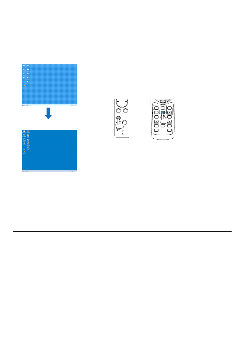
Optimizing an RGB Image Automatically
Adjusting the Image Using Auto Adjust
Optimizing an RGB image automatically.
Press the Auto Adjust button to optimize an RGB image automatically.
[Poor picture]
SELECT
ENTER
EXIT
3D
REFORM
AUTO
[Normal picture]
Press the Auto Adjust button to fine-tune the computer image or to remove any vertical banding that might appear and
to reduce video noise, dot interference or cross talk (this is evident when part of your image appears to be shimmering). This function adjusts the clock frequencies that eliminate the horizontal banding in the image. This function also
adjusts the clock phase to reduce video noise, dot interference or cross talk.
This adjustment may be necessary when you connect your computer for the first time.
ADJUST
ON/
STAND BY
POWER
STATUS
LAMP
NOTE:
• Some signals may take time or not be displayed correctly
• The Auto Adjust function does not work for component or video signals.
• If the Auto Adjust operation cannot optimize the RGB signal, try to adjust Clock and Phase manually.
E-14
Page 25
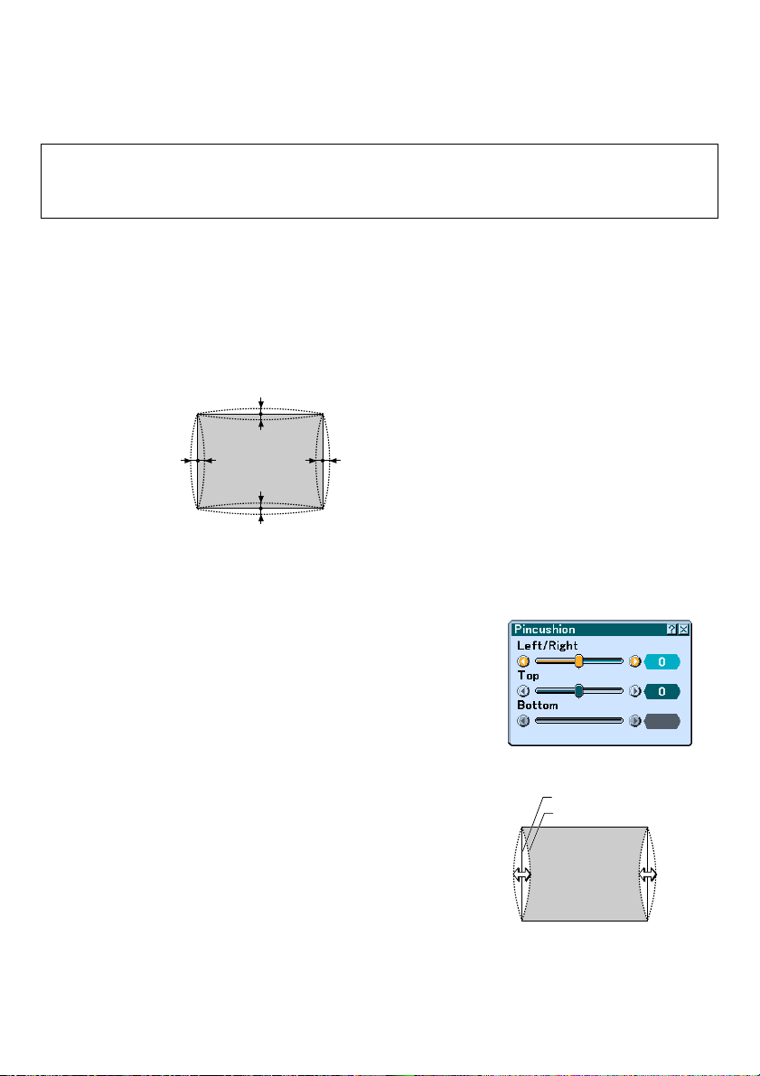
Adjusting Pincushion or Barrel Distortion (Pincushion)
If pincushion or barrel distortion become conspicuous, adjust with [Pincushion].
Important
Operating [Pincushion] will make the electronic pen unavailable.
To make the electronic pen available, use [Pincushion] to clear its correction value. Pressing and holding the 3D
REFORM button for a minimum of 2 seconds will clear the correction value.
Reference
• Pincushion or barrel distortion in this projector
The amount of pincushion and barrel distortion in this projector is 2% or less (TV distortion) in each of the
horizontal and vertical directions (for screen sizes of 40 inches to 100 inches).
As an example, the amount of distortion with a screen size of 60 inches (121.9 cm/48.0” W x 91.4 cm/36.0” H) is
within approximately 12 mm/0.47” in the horizontal direction and within approximately 9 mm/0.35” in the vertical
direction. When this projector is used with a 60-inch screen size, the amount of pincushion and barrel distortion
is at a minimum.
a
a
bb
a
a
When the amount of pincushion or barrel distortion exceed 2% (TV distortion), please check whether the projector
and screen setup conditions are suitable.
a: 1% or less of the screen height
(2% or less as TV distortion)
bb
b: 1% or less of the screen width
(2% or less as TV distortion)
1 Press the 3D REFORM button of the projector or the remote control.
The [Pincushion] screen will appear.
• Press the SELECT or button and align the cursor with [Left/
Right], then press the SELECT
ment of the left and right protrusions and indentations of the
projected image.
or button to allow adjust-
E-15
Screen (solid line)
Projected area (dotted line)
Page 26
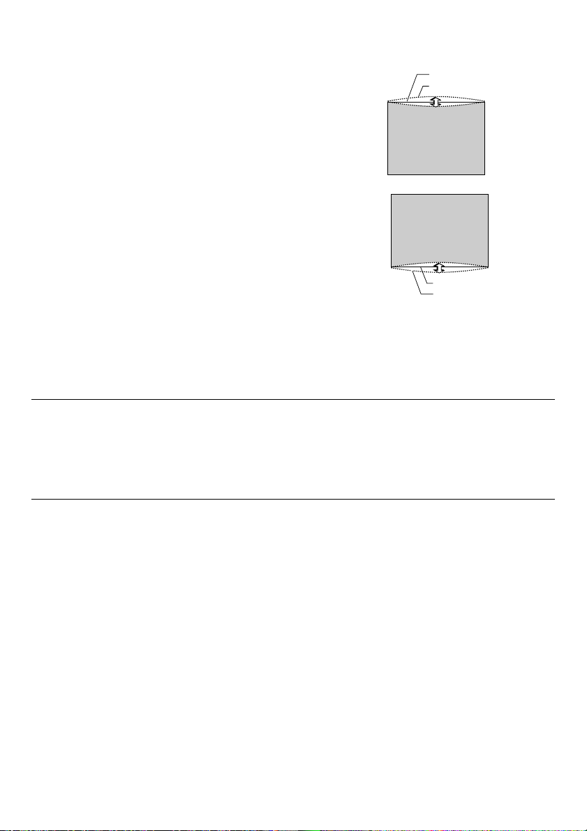
• Press the SELECT or button and align the cursor with [Top],
then press the SELECT
or button to allow adjustment of the
protrusions and indentations of the upper edge of the projected
image.
Screen (solid line)
Projected area (dotted line)
• Press the SELECT or button and align the cursor with
[Bottom], then press the SELECT
or button to allow adjustment of the protrusions and indentations of the lower edge of the
projected image.
Screen (solid line)
Projected area (dotted line)
2. Press the ENTER button when [Pincushion] is completed.
Return to the menu.
3. Press the EXIT button a few times to make the menu disappear.
NOTE:
• In the [Pincushion] screen, when the [Top] adjustment value is "0", adjustment of [Bottom] will not be possible*.
Also note that when the adjustment value of the [Top] is a small value (on the order of +5), there will be almost no change of
the image even when the [Bottom] is adjusted.
• In the [Pincushion] screen, when the [Bottom] adjustment value is less than "0", a small portion can be lost at the bottom area
of the image. To display the lost portion, use the [Digital Zoom] function to reduce the size of the projected image*.
• When [Cornerstone] or [Keystone] has already been adjusted, selection of [Pincushion] will not be possible. To display
[Pincushion], return the adjustment values of [Cornerstone] or [Keystone] to the factory shipping conditions.
* Each note for [Top] and [Bottom] is reversed when the [Ceiling Rear] or [Ceiling Front] is selected in [Orienta-
tion] .
Reference
The [Pincushion] screen can also be displayed from the menu by going to [Setup] → [Basic].
E-16
Page 27
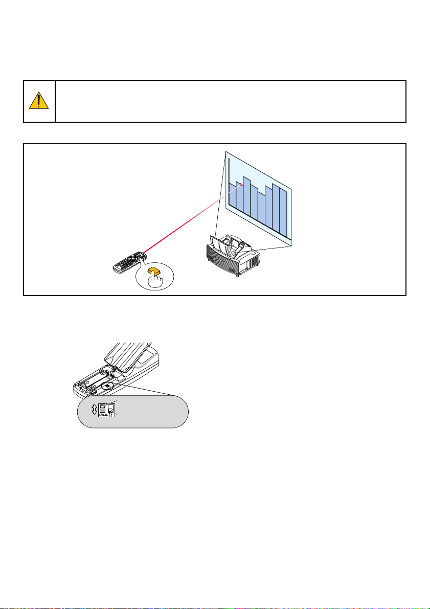
Using the Laser Pointer
You can use the laser to draw your audience's attention to a red dot that you can place on any object.
CAUTION:
• Do not look into the laser pointer while it is on.
• Do not point the laser beam at a person.
• Do not allow children to use the laser pointer.
Press and hold the LASER button to activate the laser pointer.
U
N
M
L
O
I
R
C
R
K
O
R
L
O
C
K
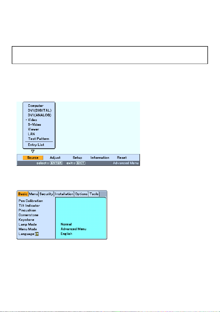
LASER
To disable the laser pointer, set the function switch to “Off”.
Decide whether to enable or disable the laser, then set the switch as necessary using the tip of a thin ball-point pen.
On this model, the other selector switch is not used.
ON
OFF
Laser enable/disable
switch
Not used
On: Enabled (the laser lights when the LASER button is pressed) [Factory default]
Off: Disabled (the laser does not light even when the LASER button is pressed)
Disable the laser when using in an environment in which the unit is accessible to children.
E-17
Page 28
Using the Electronic Pen (WT615 only)
The electronic pen and the projector’s sensors can be used to convert your whiteboard into a virtual touchscreen
which allows you to operate your projector’s menu or use the ChalkBoard feature.
Important
Before you use the electronic pen for the first time or when you have changed the position of the projector or the
screen size, be sure to use [Pen Calibration] to calibrate the electronic pen and the screen.
Pen Calibration
Calibrate so that pen touches are properly detected by the sensor on the WT615.
1. Press the MENU button on the remote control or the projector cabinet.
The menu will be displayed.
2. Press the SELECT button twice to select [Setup] and press the ENTER button.
The [Basic] menu will be displayed.
E-18
Page 29
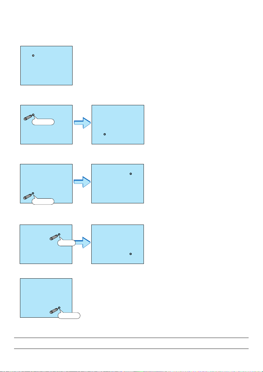
3. Press the SELECT or button to select [Pen Calibration] and press the ENTER button.
One “O ”mark will be displayed on the screen.
4. Touch the circle “O” mark lightly with the electronic pen.
Another “O” mark will be displayed on the screen.
Touch
5. Touch the circle “O” mark lightly with the electronic pen.
Another “O” mark will be displayed on the screen.
Touch
6. Touch the circle “O” mark lightly with the electronic pen.
The other “O” mark will be displayed on the screen.
Touch
7. Touch the circle “O” mark lightly with the electronic pen.
Touch
Your calibration settings are now saved.
This completes “Pen Calibration”.
NOTE: Hold the electronic pen upright against the screen when using it. Otherwise, the actual movement of the electronic pen
may not be displayed on the screen.
E-19
Page 30
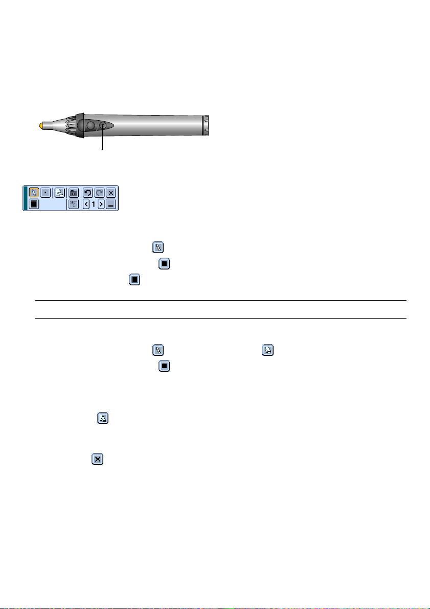
ChalkBoard Function
You can use the electronic pen to operate the ChalkBoard function.
• Start ChalkBoard
Press the button B on the electronic pen.
Button B
The ChalkBoard toolbar will be displayed at the bottom left of the screen.
• Drawing lines
[1] Tap the Drawing tool palette icon
[2] Tap the Line thickness palette icon
[3] Tap the Color palette icon
[4] Touch and hold the pen tip to the screen lightly to write characters or draw patterns.
lightly and then tap the Pen icon.
and then tap your preferred line thickness icon.
lightly and then tap your preferred line color icon.
NOTE: Hold the electronic pen upright against the screen when using it. Otherwise, the actual movement of the electronic pen
may not be displayed on the screen.
• Erasing lines
[1] Tap the Drawing tool palette icon
[2] Tap the Line thickness palette icon
[3] Touch and hold the pen tip to the screen lightly to erase lines.
and then tap the Eraser icon .
and then tap your preferred line thickness icon.
• Clear the Screen
Tap the Clear icon
• Exit ChalkBoard
Tap the Exit icon
.
.
Reference
On the WT610 you can use the ChalkBoard function when connecting a USB mouse to the projector.
E-20
Page 31

Turning off the Projector
To turn off the projector:
1. Press the POWER (ON/STAND BY) button on the projector
cabinet or the POWER OFF button on the remote control.
The "Power Off / Are you sure?" message will appear.
Cabinet controls Remote control
ENTER
AUTO
ADJUST
ON/
STAND BY
SELECT
REFORM
EXIT
3D
POWER
STATUS
LAMP
OFF
MAGNIFY
R
E
T
ON
POWER
LASER
PAGE
UP
POINTER
DOWN
N
U
E
M
N
E
R
K
-
C
C
I
L
E
X
I
T
2. Press the ENTER button or the POWER (ON/STANDBY) or
the POWER OFF button again.
The POWER indicator will glow orange. After the projector turns
off, the cooling fans keep operating for 90 seconds (Cooling-off
time).
NOTE: Immediately after turning on the projector and displaying an
image, you cannot turn off the projector for 60 seconds.
3. Turn off the Main Power switch. The POWER indicator will
go out.
CAUTION
Do not unplug the power cable from the wall outlet or do
not turn off the main power under any one of the following
circumstances.
Doing so can cause damage to the projector or PC card:
•While the projector lamp is On.
•While the cooling fans are running. (The cooling fans
continue to work for 90 seconds after the projector is turned
off).
•While the PC CARD Access Indicator lights. Doing so can
damage your PC memory card.
ENTER
AUTO
ADJUST
ON/
STAND BY
SELECT
REFORM
EXIT
3D
POWER
STATUS
LAMP
MAGNIFY
OFF
ON
POWER
LASER
PAGE
UP
POINTER
DOWN
N
U
E
M
E
R
X
E
I
T
T
N
E
R
K
-
C
C
I
L
E-21
Page 32

After Use
Preparation: Make sure that the main power is turned off.
1. Close the mirror cover.
After closing the mirror cover, lock the mirror cover by
sliding the mirror cover lock switch to the lock position.
2. Unplug the power cable.
3. Disconnect any other cables.
4. Retract adjustable tilt feet if extended.
5. Put the supplied dust-proof cover over the projector cabinet.
UN
MIRROR
LOCK
1
LOCK
UNLOCK
MIRROR
LOCK
2
E-22
Page 33

Projector
WT615/WT610
User’s Manual
The WT615 projector is not distributed in the U.S.A or Canada.
Page 34

Important Information
Safety Cautions
Precautions
Please read this manual carefully before using your NEC WT615/WT610 Projector and keep the manual handy for
future reference. Your serial number is located on the right side of your projector. Record it here:
CAUTION
To turn off main power, be sure to remove the plug from power outlet.
The power outlet socket should be installed as near to the equipment as possible, and should be easily
accessible.
CAUTION
TO PREVENT SHOCK, DO NOT OPEN THE CABINET.
NO USER-SERVICEABLE PARTS INSIDE.
REFER SERVICING TO QUALIFIED NEC SERVICE PERSONNEL.
This symbol warns the user that uninsulated voltage within the unit may be sufficient to cause electrical
shock. Therefore, it is dangerous to make any kind of contact with any part inside of the unit.
This symbol alerts the user that important information concerning the operation and maintenance of this
unit has been provided.
The information should be read carefully to avoid problems.
WARNING: TO PREVENT FIRE OR SHOCK, DO NOT EXPOSE THIS UNIT TO RAIN OR MOISTURE.
DO NOT USE THIS UNIT’S PLUG WITH AN EXTENSION CORD OR IN AN OUTLET UNLESS ALL THE PRONGS
CAN BE FULLY INSERTED.
DO NOT OPEN THE CABINET. THERE ARE HIGH-VOLTAGE COMPONENTS INSIDE. ALL SERVICING MUST
BE DONE BY QUALIFIED NEC SERVICE PERSONNEL.
DOC Compliance Notice (for Canada only)
This Class B digital apparatus meets all requirements of the Canadian Interference-Causing Equipment Regulations.
Acoustic Noise Information Ordinance-3. GSGV (for Germany only):
The sound pressure level is less than 70 dB (A) according to ISO 3744 or ISO 7779.
CAUTION
Do not look into the laser pointer while it is on and do not point the
laser beam at a person. Serious injury could result.
This label is underneath the remote control.
WARNING TO CALIFORNIA RESIDENTS:
Handling the cables supplied with this product, will expose you to lead, a chemical known to the State of California
to cause birth defects or other reproductive harm. Wash hands after handling.
© NEC Viewtechnology, Ltd. 2005
i
Page 35

Important Information
RF Interference (for USA only)
WARNING
The Federal Communications Commission does not allow any modifications or changes to the unit EXCEPT those specified by
NEC Solutions (America), Inc. in this manual. Failure to comply with this government regulation could void your right to operate
this equipment. This equipment has been tested and found to comply with the limits for a Class B digital device, pursuant to Part
15 of the FCC Rules. These limits are designed to provide reasonable protection against harmful interference in a residential
installation. This equipment generates, uses, and can radiate radio frequency energy and, if not installed and used in accordance
with the instructions, may cause harmful interference to radio communications. However, there is no guarantee that interference
will not occur in a particular installation.
If this equipment does cause harmful interference to radio or television reception, which can be determined by turning the
equipment off and on, the user is encouraged to try to correct the interference by one or more of the following measures:
• Reorient or relocate the receiving antenna.
• Increase the separation between the equipment and receiver.
• Connect the equipment into an outlet on a circuit different from that to which the receiver is connected.
• Consult the dealer or an experienced radio / TV technician for help.
For UK only: In UK, a BS approved power cable with moulded plug has a Black (five Amps) fuse installed for use with this equipment.
If a power cable is not supplied with this equipment please contact your supplier.
Important Safeguards
These safety instructions are to ensure the long life of your projector and to prevent fire and shock. Please read them
carefully and heed all warnings.
Installation
1. For best results, use your projector in a darkened room.
2. Place the projector on a flat, level surface in a dry area away from dust and moisture.
3. Do not place your projector in direct sunlight, near heaters or heat radiating appliances.
4. Exposure to direct sunlight, smoke or steam can harm internal components.
5. Handle your projector carefully. Dropping or jarring can damage internal components.
6. Do not place heavy objects on top of the projector.
7. If you wish to have the projector installed on the ceiling:
a. Do not attempt to install the projector yourself.
b. The projector must be installed by qualified technicians in order to ensure proper operation and reduce the
risk of bodily injury.
c. In addition, the ceiling must be strong enough to support the projector and the installation must be in accor-
dance with any local building codes.
d. Please consult your dealer for more information.
Place the projector in a horizontal position
The tilt angle of the projector should not exceed 10 degrees, nor should the projector be installed in any way other than
the desktop and ceiling mount, otherwise lamp life could decrease dramatically.
10°
10°
10°
10°
10°
10°
ii
Page 36

Important Information
Fire and Shock Precautions
1. Ensure that there is sufficient ventilation and that vents are unobstructed to prevent the build-up of heat inside
your projector. Allow at least 4 inches (10 cm) of space between your projector and a wall.
2. Prevent foreign objects such as paper clips and bits of paper from falling into your projector.
Do not attempt to retrieve any objects that might fall into your projector. Do not insert any metal objects such as
a wire or screwdriver into your projector. If something should fall into your projector, disconnect it immediately
and have the object removed by a qualified NEC service personnel.
3. Do not place any liquids on top of your projector.
4. Do not look into the mirror or the light source while the projector is on. Serious damage to your eyes could
result.
5. Keep any items such as magnifying glass out of the light path of the projector. The light being projected from the
mirror is extensive, therefore any kind of abnormal objects that can redirect light coming out of the mirror, can
cause unpredictable outcome such as fire or injury to the eyes.
6. Do not block the light path between the light source and the final mirror with any objects. Doing so could cause
the object to catch on fire.
7. The projector is designed to operate on a power supply of 100-240V AC 50/60 Hz. Ensure that your power
supply fits this requirement before attempting to use your projector.
8. Handle the power cable carefully and avoid excessive bending.
A damaged cord can cause electric shock or fire.
9. If the projector is not to be used for an extended period of time, disconnect the plug from the power outlet.
10. Do not touch the power plug during a thunderstorm. Doing so can cause electrical shock or fire.
11. Do not handle the power plug with wet hands.
12. When using a LAN cable:
For safety, do not connect to the connector for peripheral device wiring that might have excessive voltage.
CAUTION
• Do not try to touch the ventilation openings on the both sides as it can become heated while the projector is
turned on.
• Do not attempt to move or carry the projector using the mirror cover.
Doing so can result in the projector overturning and causing injury. Using the two side handles is the proper
way to move the projector.
When carrying or transporting the projector, close and lock the mirror cover with the mirror cover lock switch.
• The carrying handles are designed for the purpose of carrying the projector. Do not hang from the projector by
the carrying handles in a ceiling mounted installation. Doing so may result in the carrying handles separating
from the unit or the projector may separate from the mount resulting in personal injury.
• Select [High] in Fan mode if you continue to use the projector for consecutive days. (From the menu, select
[Setup] → [Options] → [Fan Mode] → [High].)
• Do not unplug the power cable from the wall outlet under any one of the following circumstances.
Doing so can cause damage to the projector:
* While the projector's lamp is on.
* While the cooling fans are running. (The cooling fans continue to work for 90 seconds after the projector is
turned off).
* While the PC CARD Access Indicator lights. Doing so can damage your PC memory card.
iii
Page 37

Important Information
Lamp Replacement
•To replace the lamp, follow all instructions provided on page 134.
• Be sure to replace the lamp when the message “The lamp has reached the end of its usable life. Please
replace the lamp.” appears. If you continue to use the lamp after the lamp has reached the end of its usable
life, the lamp bulb may shatter, and pieces of glass may be scattered in the lamp case. Do not touch them as the
pieces of glass may cause injury.
If this happens, contact your NEC dealer for lamp replacement.
• Allow a minimum of 90 seconds to elapse after turning off the projector. Then turn off the main power switch,
disconnect the power cable and allow 60 minutes to cool the projector before replacing the lamp.
iv
Page 38

Table of Contents
Important Information ...........................................................................i
1. Introduction ...................................................................................... 1
What's in the Box? ........................................................................................................ 2
Introduction to the Projector ......................................................................................... 3
Part Names of the Projector ......................................................................................... 5
Opening and Closing the Mirror Cover ................................................................... 6
Top Features ........................................................................................................... 7
Te r minal Panel Features ......................................................................................... 8
Part Names of the Remote Control ............................................................................ 10
Battery Installation ................................................................................................ 12
Operating Range for Wireless Remote Control..................................................... 12
Remote Control Precautions ................................................................................. 12
Using the Remote Control in Wired Operation...................................................... 12
Part Names and Functions of the Supplied Electronic Pen (WT615 only) ................. 13
Battery Installation ................................................................................................ 13
Electronic Pen Precautions ................................................................................... 13
2. Installation and Connections ....................................................... 14
Setting Up the Screen and the Projector .................................................................... 16
Making Connections ................................................................................................... 19
When Viewing a DVI Digital Signal ....................................................................... 19
Connecting Your PC or Macintosh Computer........................................................ 19
To connect SCART output (RGB) ......................................................................... 20
Using two Analog COMPUTER inputs simultaneously ......................................... 21
Connecting an External Monitor ........................................................................... 22
Connecting Your DVD Player................................................................................. 23
Connecting Your VCR or Laser Disc Player .......................................................... 24
Connecting to a Network....................................................................................... 25
Inserting and Removing a PC Card ...................................................................... 27
Connecting the Supplied Power Cable ................................................................. 29
3. Projecting an Image (Basic Operation)...................................... 30
Tur ning on the Projector ............................................................................................. 31
Adjusting the Position and Size of the Projected Image (Focus Adjustments) ........... 33
Selecting a Source ..................................................................................................... 40
Optimizing an RGB Image Automatically ................................................................... 41
Tur ning Up or Down Volume ....................................................................................... 41
Adjusting Pincushion or Barrel Distortion (Pincushion) .............................................. 42
Using the Laser Pointer .............................................................................................. 44
쐊 Using the Electronic Pen (WT615 only)...................................................................... 45
쐎 Tur ning off the Projector ............................................................................................. 48
쐅 After Use..................................................................................................................... 49
v
Page 39

Table of Contents
4. Convenient Features ...................................................................... 50
Tur ning Off the Image and Sound............................................................................... 51
Freezing a Picture....................................................................................................... 51
Using the Pointer ........................................................................................................ 51
Enlarging and Moving a Picture.................................................................................. 52
Getting Integrated Help .............................................................................................. 52
Using a USB Mouse ................................................................................................... 53
Using the Remote Mouse Function ............................................................................ 54
Making Freehand Drawings on a Projected Image (ChalkBoard) .............................. 55
쐎
Storing Images Displayed on the Projector on the PC card or USB memory (Capture)
쐅 Preventing Unauthorized Use of the Projector ........................................................... 57
쐈 Using a USB Memory Device or USB Memory Card Reader ..................................... 62
쐉 Operation Using an HTTP Browser ............................................................................ 63
씈
Using the Projector to Operate a Computer Connected on a Network (Desktop Control Utility 1.0)
.......... 56
........ 66
5. Using the Viewer ............................................................................. 71
Making the Most out of the Viewer Function ............................................................... 72
Operating the Viewer Function from the Projector (playback) .................................... 73
쐋 Changing Background Logo ....................................................................................... 79
6. Using On-Screen Menu ................................................................. 80
Using the Menus......................................................................................................... 81
Menu tree ................................................................................................................... 82
Menu Elements........................................................................................................... 84
Menu Descriptions & Functions [Source] ................................................................... 85
쐄 Menu Descriptions & Functions [Adjust] ..................................................................... 88
쐂 Menu Descriptions & Functions [Setup] ..................................................................... 98
쐆 Menu Descriptions & Functions [Information] ........................................................... 126
쐊 Menu Descriptions & Functions [Reset] ................................................................... 129
7. Maintenance .................................................................................. 131
Handling and Care of Mirror Surface ........................................................................ 132
쐇 Cleaning the Cabinet ................................................................................................ 133
쐋 Replacing the Lamp................................................................................................. 134
8. Appendix ......................................................................................... 137
Troubleshooting ........................................................................................................ 138
Specifications ........................................................................................................... 142
Cabinet Dimensions ................................................................................................. 144
Pin Assignments of D-Sub COMPUTER Input Connector ....................................... 145
Compatible Input Signal List ..................................................................................... 146
PC Control Codes and Cable Connection ................................................................ 147
Using Software Keyboard ......................................................................................... 148
Troubleshooting Check List....................................................................................... 149
vi
Page 40

1
Introduction
○○○○○○○○○○○○○○○○○○○○○○○○○○○○○○○○○○○○○○○○
What's in the Box? ....................................................... 2
Introduction to the Projector ........................................ 3
Part Names of the Projector ........................................ 5
Opening and Closing the Mirror Cover ................................................................... 6
Top Features........................................................................................................... 7
Te r minal Panel Features......................................................................................... 8
Part Names of the Remote Control ........................... 10
Battery Installation ................................................................................................ 12
Operating Range for Wireless Remote Control .................................................... 12
Remote Control Precautions ................................................................................ 12
Using the Remote Control in Wired Operation ..................................................... 12
Part Names and Functions of
the Supplied Electronic Pen (WT615 only) ............ 13
Battery Installation ................................................................................................ 13
Electronic Pen Precautions .................................................................................. 13
1
Page 41

What's in the Box?
Make sure your box contains everything listed. If any pieces are missing, contact your dealer.
Please save the original box and packing materials if you ever need to ship your Projector.
UNL
M
OCK
IRROR
LOCK
1. Introduction
Power cable
(7N080204) US
(7N080008) EU
Important
Information
For North America only
Registration card
Limited warranty
For Europe only
Guarantee policy
Setup
Guide
NEC
Network
Setup Guide
Projector
Remote Control
Cable
(7N520019)
CD-ROM
User’s manual and User Supportware 2
WT615 only
• Electronic pen and battery
(7N900611)
Remote control
(7N900501)
USB cable
(7N520045)
(AA⳯1)
Batteries (AAA ⳯ 2)
RGB/VGA signal cable
(7N520032)
• Security sticker
• Mirror cleaning cloth (24BS7251)
• Dust-proof cover (24BS7272)
• USB memory device (7N960201)
See page 60.
• CD-ROM
User Supportware 2 Plus
(eBeam Interactive Software)
2
• eBeam Interactive Software Setup Guide
Page 42

1. Introduction
Introduction to the Projector
This section introduces you to the WT615/WT610 Projector and describes key features and controls.
Congratulations on Your Purchase of the WT615/WT610 Projector
The WT615/WT610 is a sophisticated four aspherical mirror XGA projector that produces an enhanced display. With
the WT615/WT610 you will be able to project images up to 100” (measured diagonally). Enjoy crisp and sharp large
screen display from your PC, workstation or Macintosh computer, DVD player, VCR, satellite hookup, HDTV source, )
and images from your digital camera PC Card, compact flash memory or USB storage device. The WT615/WT610
provides for enhanced security options to help deter projector theft and provides for full projector control through the
PC control port (mini DIN 8Pin) and LAN support. With input and output flexibility and a full function remote, the
WT615/WT610 lets you enjoy larger than life viewing from a compact and easy to setup and use projector.
Features you’ll enjoy on the WT615/WT610:
• Extremely short focal length
• 40" to 100" diagonal image display from 26 inches (66 cm) or less to the screen
• The electronic pen and the projector can be used to convert your whiteboard into a virtual touchscreen. (WT615
only)
• Built-in Wall Color Correction presets provide for adaptive color correction when projecting onto non-white
screen material (or a wall).
• USB memory or PC card interfaces provide for computer-free presentations.
• Enhanced smart security settings for password protection, cabinet control panel lock, menu lock and PC card
protection key to help prevent unauthorized access, adjustments and theft deterrence.
• High resolution display - up to UXGA compatible, XGA native resolution.
•Variable audio out control of external amplified speakers via the projector remote.
• Extensive user adjustable picture and color management settings.
• Display 16:9 or 4:3 aspect ratio sources and fill the screen.
• HDTV (1080i, 720p) and SDTV (480p/576p, 480i/576i) compatibility.
• Digital photo viewer to display larger than life images from your digital cameras PC card, compact flash card or
USB storage device.
• Wireless networking capable.
Present from anywhere in the room when using as a wireless LAN projector, no physical signal cable connec-
tion to a PC is required.
* The NEC optional wireless LAN card is required (NWL-100A or NWL-100E See page 25.).
• Supplied User Supportware 2 CD-ROM containing five software utilities allowing you to make the most of your
NEC projector.
• Eco-mode lamp technology for increased lamp life, reduced energy consumption and overall total cost of
ownership savings.
• Built-in laser pointer on the supplied remote control allows you to draw your audience's attention in a presentation.
3
Page 43

1. Introduction
About this user's manual
The fastest way to get started is to take your time and do everything right the first time. Take a few minutes now to
review the user's manual. This may save you time later on. At the beginning of each section of the manual you'll find an
overview. If the section doesn't apply, you can skip it.
• IBM is a trademark or registered trademark of International Business Machines Corporation.
• Mac, Macintosh and PowerBook are trademarks of Apple Computer, Inc., registered in the U.S. and other
countries.
• Windows, Windows 98, Windows Me, Windows XP or Windows 2000 are trademarks or registered trademarks
of Microsoft Corporation.
• Digital Light Processing and DLP are trademarks of Texas Instruments.
• Ulead is a trademark and/or registered trademark of Ulead Systems, Inc.
• eBeam and the eBeam logo are trademarks or registered trademarks of Luidia, Inc.
• Other product and company names mentioned in this user’s manual may be the trademarks or registered
trademarks of their respective holders.
4
Page 44

Part Names of the Projector
P
C
C
A
R
D
R
-A
U
D
IO
IN
-L
/M
O
N
O
V
ID
E
O
IN
S
-V
ID
E
O
IN
D
V
I-I IN
D
V
I-I
A
U
D
IO
IN
A
U
D
IO
O
U
T
P
C
C
O
N
T
R
O
L
R
E
M
O
T
E
IN
C
O
M
P
U
T
E
R
IN
M
O
N
IT
O
R
O
U
T
C
O
M
P
U
T
E
R
U
S
B
1. Introduction
Front indicator
Lights blue to indicate that
the projector is turned on
or in the Standby mode.
NOTE: When [Standby Mode]
U
N
M
L
O
IR
C
R
K
O
R
L
O
C
K
Mirror cover
Mirror cover lock switch
is set to “Power-saving”, this
indicator lights blue only with
power on.
Speaker
Ventilation (outlet)
Foot
Remote sensor
Foot
Lamp cover
Lamp cover screw
Built-in Security Slot ( )*
Speaker
Foot
* This security slot supports the MicroSaver® Security System. MicroSaver® is a registered trademark of
Kensington Microware Inc. The logo is trademarked and owned by Kensington Microware Inc.
Carrying handle
K
C
LO
R
O
CK
IRR
LO
M
UN
Sensor for Electronic pen
Controls
(WT615 only)
LAMP
STATUS
POWER
ON/
STAND BY
3D
REFORM
EXIT
ADJUST
AUTO
ENTEER
SELECT
SOURCE
MENU
FOCUS
PC CARD
Te r minal panel
Ventilation (outlet)
Ventilation (inlet)
Main Power Switch
AC Input
Remote sensor
5
Page 45

Opening and Closing the Mirror Cover
1. Introduction
To open the mirror cover:
1. Slide the mirror cover lock switch to the unlock position.
U
NL
M
O
I
RR
C
K
O
R
L
O
C
K
1
2. Slowly open the mirror cover holding both ends.
U
N
M
L
O
I
R
C
R
K
O
R
L
O
C
K
2
NOTE:
• Do not release your hold of the mirror cover until the mirror cover
is fully open.
• Do not apply excessively strong pressure against the mirror cover
or mirror surface while opening it.
• Keep finger prints off the mirror surface. Leaving finger prints in
the mirror surface might cause an unwanted shadow and poor
picture quality.
To close the mirror cover:
1. Slowly close the mirror cover while holding both ends.
U
N
M
LO
IR
CK
R
O
R
LO
C
1
K
NOTE:
• Do not release your hold of the mirror cover until the mirror cover
is fully closed.
• Do not apply excessively strong pressure against the mirror cover
or mirror surface while closing it.
• Keep finger prints off the mirror surface. Leaving finger prints in
the mirror surface might cause an unwanted shadow and poor
picture quality.
2. Slide the mirror cover lock switch to the lock position.
U
N
M
L
O
IR
C
R
K
O
R
L
O
C
K
2
NOTE:
• The projector cannot be turned on when the mirror cover is closed.
• Keep any items out of the light path or the mirror. Failure to do so
may cause objects to catch on fire in unexpected places.
• The projector has a sensor which detects an object in front of the
largest mirror or in the light path. If the sensor detects any object,
the projector will not turn on. If this happens while the projector is
turned on, the image is muted. In either case the STATUS indicator
lights in red.
• The projector has a temperature sensor which detects heat. If the
sensor detects excessive heat in the bottom of the mirror or in the
light path, the projector will not turn on. If this happens while the
projector is turned on, the projector will turn off (Standby mode).
In either case the STATUS indicator flashes in red.
6
Page 46

1. Introduction
Top Features
FOCUS
MENU
PC CARD
SOURCE
5
13
8
9
10
11
6
1
1. POWER Button (ON / STAND BY)
Use this button to turn the power on and off when the
main power is supplied and the projector is in standby
mode.
NOTE: To turn on the projector, press and hold this button
for a minimum of two seconds. To turn off the projector,
press this button twice.
2. POWER Indicator ( )
When this indicator is green, the projector is on; when
this indicator is orange, it is in standby mode. See the
Power Indicator section on page 138 for more details.
3. STATUS Indicator
If this light blinks red rapidly, it indicates that an error
has occurred, the lamp cover is not attached properly
or the projector has overheated. If this light remains
orange, it indicates that you have pressed a cabinet
key while the Cabinet Button is locked. See the Status Indicator section on page 138 for more details.
4. LAMP Indicator
If this light blinks red rapidly, it's warning you that the
projection lamp has exceeded 2000 hours (up to 4000
hours in Eco mode) of service. After this light appears,
replace the lamp as soon as possible. (See page 134).
If this is lit green continually, it indicates that the lamp
mode is set to Eco. See the Lamp Indicator section
on page 138 for more details.
SELECT
ENTER
AUTO
ADJUST
ON/
STAND BY
EXIT
3D
REFORM
POWER
STATUS
LAMP
12
7
2
3
4
5. SOURCE Button
Use this button to select a video source such as a PC,
VCR, DVD player or Viewer (PC card).
Press and release this button quickly to display the
Source List.
Each time this button is pressed for a minimum of ONE
second, the input source will change as follows:
Computer → DVI (DIGITAL) → DVI (ANALOG) →
Video → S-Video → Viewer → Computer → ...
If no input signal is present, the input will be skipped.
6. AUTO ADJUST Button
Use this button to adjust an RGB source for an optimal picture. See page 41.
7. 3D REFORM Button
Press this button to enter 3D Reform mode to correct
the distortion, and make the image square.
Each time this button is pressed, the item will change
as follows:
Pincushion → Cornerstone → Keystone → ... (the
three items are available only when no adjustment is
made)
8. FOCUS (+) (–) Buttons
Adjusts the focus.
9. MENU Button
Displays the menu.
10. SELECT 왖왔왗왘 (+) (–) / Volume Buttons
왖왔 : Use these buttons to select the menu of the
item you wish to adjust.
왗왘 : Use these buttons to change the level of a
selected menu item. When no menus appear,
these buttons work as a volume control.
When the pointer is displayed, these 왖왔왗왘 buttons
move the pointer.
11. ENTER Button
Executes your menu selection and activates items
selected from the menu.
12. EXIT Button
Pressing this button will return to the previous menu
with saving changes.
While you are in the main menu, pressing this button
will close the menu.
13. PC CARD Access Indicator
Lights while accessing a PC card.
7
Page 47

Te r minal Panel Features
1. Introduction
REMOTE
IN
PCCONTROL
AUDIO IN
R
L
/MONO
VIDEO IN
PC CARD
S-VIDEO IN DVI-I IN
1. COMPUTER IN / Component Input Connector
(Mini D-Sub 15 Pin)
Connect your computer or other analog RGB equipment such as IBM compatible or Macintosh computers. Use the supplied RGB/VGA signal cable to connect to your computer. This also serves as a component input connector that allows you to connect a component video output of component equipment such
as a DVD player. This connector also supports SCART
output signal. See page 20 for more details.
2. COMPUTER AUDIO IN Mini Jack (Stereo Mini)
This is where you connect audio output from your computer or DVD player. A commercially available audio
cable is required.
3. DVI-I IN Connector (DVI-I 29 Pin)
Connect a computer with a DVI output using a commercially available DVI-D cable.
This connector can be used to accept digital and analog signal output from a computer with a DVI connector.
4. DVI-I AUDIO IN Mini Jack (Stereo Mini)
This is where you connect the audio output from your
computer when connected to the DVI input. A commercially available audio cable is required.
5. MONITOR OUT Connector (Mini D-Sub 15 Pin)
You can use this connector to loop your computer
image to an external monitor from the COMPUTER
or the DVI-I input source.
The RGB analog signal set on “OUT Terminal” is output during Standby mode. See pages 22 and 122.
12131514
USB
COMPUTER IN MONITOR OUT
3789
1 5
2410 11
AUDIO IN AUDIO OUT
DVI-I COMPUTER
6
6. AUDIO OUT Mini Jack (Stereo Mini)
Connect an additional audio equipment here to listen
to audio coming from your COMPUTER, DVI-I, VIDEO
or S-VIDEO input.
7. S-VIDEO IN Connector (Mini DIN 4 Pin)
Here is where you connect the S-Video input from an
external source like a VCR.
NOTE: S-Video provides more vivid color and higher
resolution than the traditional composite video format.
8. VIDEO IN Connector (RCA)
Connect a VCR, DVD player, laser disc player, or document camera here to project video.
9. VIDEO AUDIO IN Jacks (RCA)
L: This is your left channel audio input for stereo
sound coming from the VIDEO source.
R: This is your right channel audio input for stereo
sound from the VIDEO source.
10. REMOTE IN Jack (Mini Jack)
Connect your remote control cable here for wired operation.
11. PC CONTROL Port (Mini DIN 8 Pin)
Use this port to connect your PC or control system to
control your projector via a serial cable. This enables
you to control the projector using serial communication protocol. An optional serial cable (CA03D: 9Pin
D-Sub to 8 Pin Mini DIN) is required for this port. You
can also control the projector by using PC Control
Utility 3.0 contained on the supplied User Supportware
2 CD-ROM.
To do so you must first have PC Control Utility 3.0
installed on your PC. If you are writing your own program, typical PC control codes are on page 147.
8
Page 48

Te r minal Panel Features
1. Introduction
REMOTE
IN
R
PCCONTROL
AUDIO IN
L
/MONO
VIDEO IN
PC CARD
S-VIDEO IN DVI-I IN
12. USB Port (Type B)
Connect this port to the USB port (type A) of your PC
using the supplied USB cable. You can operate your
computer's mouse functions from the remote control.
13. USB Port (Type A)
Connect a commercially available USB memory device or mouse that supports USB. You can operate
the menu or Viewer with the USB mouse via this port.
Note that this port should not be connected to a computer and that there may be some brands of USB
mouse that the projector does not support.
12131514
USB
COMPUTER IN MONITOR OUT
3789
14. PC CARD Slot
15. PC CARD Eject Button
1 5
Insert a PC card, commercially available LAN card or
NEC optional wireless LAN card here.
NOTE: A dummy card is inserted into each slot at the time
of shipment. First remove the dummy cards before use.
Press to eject a PC card partially.
2410 11
AUDIO IN AUDIO OUT
DVI-I COMPUTER
6
9
Page 49

쐏 Part Names of the Remote Control
1. Introduction
5
6
10
11
12
2
1
3
6. MAGNIFY (+) (–) Buttons
Use these buttons to adjust the image size.
The image can be magnified about the center of the
screen up to 400%. See page 52.
OFF
MAGNIFY
R
E
T
N
E
VIDEO
ASPECT
PIC-MUTE
VOLUME
FREEZE
COMPUTER
POWER
LASER
POINTER
N
U
E
M
R
K
-
C
C
I
L
AUTO ADJ.
HELP
ON
PAGE
UP
DOWN
E
X
I
T
VIEWER
SLIDE
ZOOMFOCUS
3D REFORM
4
7
9
8
13
14
7. LASER Button
Press and hold this button to activate the laser pointer.
When lit, you can use the laser to draw your audience's
attention to a red dot that you can place on any object. See page 44.
8. POINTER Button
Press this button to display the projector pointer. You
can move your pointer icon to the area you want on
the screen using the SELECT 왖왔왗 or 왘 button. See
page 51.
9. PAGE (UP) (DOWN) Buttons
Use these buttons to scroll the viewing area of the
window or to move to the previous or next slide in
PowerPoint on your computer when the supplied USB
cable is connected with your computer.
10. MENU Button
Displays the menu for various settings and adjustments.
1. Infrared Transmitter/Laser Pointer
Tr ansmits an infrared signal when any button other
than LASER is pressed.
Direct the remote control toward the remote sensor
on the projector cabinet.
Beams a laser light when the Laser button is pressed.
CAUTION:
* Do not look into the laser pointer while it is on.
* Do not point the laser beam at a person.
2. Remote Jack
Connect your remote control cable here for wired operation.
3. LED
Flashes when any button is pressed.
4. POWER ON Button
When the main power is on, you can use this button
to turn your projector on.
NOTE: To turn on the projector, press and hold the
POWER ON button for a minimum of two seconds.
5. POWER OFF Button
You can use this button to turn your projector off.
NOTE: To turn off the projector, press the POWER OFF
button twice.
11. SELECT 왖왔왗왘 Button
This button is used for projector’s menu operation and
moving the magnified image.
This button also works as a computer mouse when
the supplied USB cable is connected with your computer.
12. ENTER Button
Executes your menu selection and activates items
selected from the menu.
13. EXIT Button
Returns to the previous menu.
While you are in the main menu, pressing this button
will close the menu.
14. R-CLICK Button
Works as the mouse right button when the supplied
USB cable is connected with your computer.
10
Page 50

1. Introduction
15. L-CLICK Button
Works as the mouse left button when the supplied
USB cable is connected with your computer.
16
21
22
23
24
27
OFF
MAGNIFY
R
E
T
N
E
VIDEO
ASPECT
PIC-MUTE
VOLUME
FREEZE
COMPUTER
AUTO ADJ.
POWER
LASER
POINTER
N
U
E
M
R
-
C
C
I
L
HELP
K
VIEWER
ZOOMFOCUS
3D REFORM
ON
PAGE
UP
DOWN
SLIDE
E
X
I
T
17
19
18
20
26
28
25
15
20. SLIDE (+) (–) Buttons
Press (+) to select the next folder or slide and press
(–) to select the previous folder or slide.
21. ASPECT Button
Press this button to display the Aspect Ratio select
menu. See page 90.
22. PIC-MUTE Button
This button turns off the image and sound for a short
period of time. Press again to restore the image and
sound. See page 51.
23. HELP Button
Provides the online help. See page 52.
24. VOLUME (+) (–) Buttons
Press (+) to increase the volume and (–) to decrease
it. See page 41.
25. FOCUS (+) (–) Buttons
Adjust the focus.
26. ZOOM (+) (–) Buttons
Reduces the image size between 80% and 100%.
27. FREEZE Button
This button will freeze a picture. Press again to resume motion. See page 51.
28. 3D REFORM Button
Press this button to enter 3D Reform to correct the
pincushion, the cornerstone or the keystone distortion, and make the image square. See pages 42 and
99 - 102.
16. VIDEO Button
Press this button to toggle between Video and S-Video
inputs.
17. COMPUTER Button
Press this button to select the COMPUTER, DVI (DIGITAL) or DVI (ANALOG) input.
18. AUTO ADJ. Button
Use this button to adjust an RGB source (COMPUTER) for an optimal picture. See page 41.
19. VIEWER Button
Press this button to select the Viewer source. See page
71.
11
Page 51

Battery Installation
1. Introduction
1
Remove the battery cover.
NOTE: Do not pull the battery
cover by force. Doing so can
result in its complete removal.
2
Remove both old batteries and
install new ones (AAA). Ensure
that you have the batteries' polarity (+/ –) aligned correctly.
3
Slip the cover back over the batteries until it snaps into place.
NOTE: Do not mix different types of
batteries or new and old batteries.
2
2
1
1
Operating Range for Wireless Remote Control
7m/22 feet
Remote control
7m/22 feet
30°
30°
Remote control
• The infrared signal operates by line-of-sight up to a distance of about 22 feet/7 m and within a 60-degree angle of
the remote sensor on the projector cabinet.
• The projector will not respond if there are objects between the remote control and the sensor, or if strong light falls
on the sensor.
Weak batteries will also prevent the remote control from properly operating the projector.
Remote sensor on the projector cabinet
30°
30°
Remote Control Precautions
• Handle the remote control carefully.
• If the remote control gets wet, wipe it dry immediately.
•Avoid excessive heat and humidity.
• If you will not be using the remote control for a long time, remove the batteries.
• Do not place the batteries upside down.
• Do not use new and old batteries together, or use different types of batteries together.
• Dispose of used batteries according to your local regulations.
Using the Remote Control in Wired Operation
Connect one end of the supplied remote cable to the REMOTE mini jack and the other end to the remote jack on the
remote control.
REMOTE
IN
PCCONTROL
PC CARD
REMOTE
IN
S-VIDEO IN DVI-I IN
AUDIO IN
VIDEO IN
L
R
/MONO
AUDIO IN AUDIO OUT
USB
DVI-I COMPUTER
COMPUTER IN MONITOR OUT
NOTE: Inserting the remote cable into the REMOTE IN jack will
automatically change the projector’s Standby mode to Normal
mode even if Power-saving mode has been selected.
12
Page 52

1. Introduction
Part Names and Functions of the Supplied Electronic Pen (WT615 only)
The WT615 comes with an electronic pen.
The electronic pen works as a USB mouse connected to the projector. See page 53 for connecting a USB mouse.
The electronic pen and the projector’s sensors can be used to convert your whiteboard into a virtual touchscreen which
allows you to operate your projector’s menu or use the ChalkBoard feature. See “ Using the Electronic Pen” on page 45.
Important
Before you use the electronic pen or when you have changed the position of the projector or the screen size, be sure
to use [Calibration] to calibrate the electronic pen and the screen.
Button B
Pen tip
Button A
The buttons work as computer mouse buttons.
Pen tip ................... Left click button
Button A ................ Right-click button
Button B ................ Button to turn on or off the ChalkBoard toolbar.
NOTE:
• Button A or B must be pressed and held for a minimum of 0.5 second.
• Pressing and holding the buttons A and B at the same time for a minimum of 0.5 second will change to “Pen Calibration”
mode. See also page 47.
Requirements for the Electronic Pen Function
• Screen size: 40” to 80”
• Projector orientation: “Desktop Front” and “Ceiling Front”
• [Screen Type]: “4:3”
• [Aspect Ratio]: “4:3”
• Digital Zoom: 100%
• [Cornerstone] and [Keystone]: Not performed
• Operating temperature: 59 to 95°F (15 to 35°C)
• [Resolution]: "Auto"
NOTE: Do not hold this part. Otherwise, the electronic pen
may not work properly.
Battery Installation
123
Electronic Pen Precautions
• Handle the electronic pen carefully.
• If the electronic pen gets wet, wipe it dry immediately.
•Avoid excessive heat and humidity.
• If you will not be using the electronic pen for a long time, remove the battery.
• Dispose of a used battery according to your local regulations.
13
Page 53

2
Installation and Connections
○○○○○○○○○○○○○○○○○○○○○○○○○○○○○○○○○○○○○○○○
Setting Up the Screen and the Projector ................... 16
Making Connections .................................................. 19
When Viewing a DVI Digital Signal ....................................................................... 19
Connecting Your PC or Macintosh Computer ....................................................... 19
To connect SCART output (RGB)......................................................................... 20
Using two Analog COMPUTER inputs simultaneously ........................................ 21
Connecting an External Monitor ........................................................................... 22
Connecting Your DVD Player ................................................................................ 23
Connecting Your VCR or Laser Disc Player .......................................................... 24
Connecting to a Network ...................................................................................... 25
Inserting and Removing a PC Card ...................................................................... 27
Connecting the Supplied Power Cable ................................................................. 29
14
Page 54

2. Installation and Connections
This section describes how to set up your projector and how to connect video and audio sources.
When installing the projector for the first time, read the WT615/WT610 Setup Guide carefully.
Your projector is simple to set up and use.
But before you get started you must first:
1. Set up a screen and the projector.
NOTE: Using a warped screen can cause an image to appear distorted.
2. Connect your computer or video equipment to the projector. See page 19 to 28.
NOTE: To connect a network, see page 25.
3. Connect the supplied power cable. See page 29.
NOTE: Ensure that the power cable and any other cables are disconnected before moving the projector. When moving the
projector or when it is not in use, close the mirror cover on the top cabinet.
15
Page 55

2. Installation and Connections
Setting Up the Screen and the Projector
1. Refer to "Throw Distance (C)" in the diagram and use a distance between the screen and projector that corresponds to the screen size.
As an example, when projecting to a 60" screen, set the projector with a separation of approximately 10.4"/26.3
cm from the screen.
2. Refer to "Height (D)" below and adjust the screen height, or adjust the height of the projector stand.
As an example, when projecting to a 60" screen, adjust the height from the feet of the projector to the lower
edge of the screen to approximately 19.0"/48.2 cm.
Screen size
(inch)
40
45
50
55
60
65
67
70
72
75
78
80
84
85
90
95
96
100
Height (B)
mm inch
659
729
799
869
939
1010
1037
1080
1107
1149
1191
1219
1275
1289
1359
1428
1443
1499
25.9
28.7
31.5
34.2
37.0
39.7
40.8
42.5
43.6
45.2
46.9
48.0
50.2
50.7
53.5
56.2
56.8
59.0
Throw distance (C)
mm inch
64
114
164
214
263
313
332
362
381
412
441
461
500
510
559
609
619
659
Screen center
B
D
Back of projector
C
Projector foot
NOTE
• There is a tolerance of +/–5% because of design values.
• The projection distance and the lower edge of the screen
are calculated using a 4:3 aspect ratio.
Height (D)
2.5
4.5
6.4
8.4
10.4
12.3
13.1
14.3
15.0
16.2
17.4
18.1
19.7
20.1
22.0
24.0
24.4
25.9
120
100
80
60
40
Screen size (inch)
20
mm inch
354
386
418
450
482
514
526
546
558
577
596
609
635
641
673
704
711
737
0
0 100 200 300 400 500 600 700
13.9
15.2
16.5
17.7
19.0
20.2
20.7
21.5
22.0
22.7
23.5
24.0
25.0
25.2
26.5
27.7
28.0
29.0
Throw distance C (mm)
120
100
80
60
40
Screen size (inch)
20
0
051015 20 25 30
Throw distance C (inch)
16
Page 56

2. Installation and Connections
Screens Suited
• The projector can accommdate screen sizes from 40” (81.3 cm/32.0” W ⳯ 61.0 cm/24.0” H)
to 100 inch (203.2 cm/80.0” W ⳯ 152.4 cm/60.0” H).
40"-100"
• Use a panel or tension type screen that has a flat surface.
Recommended
Do not use roll type screens and other screens that bend or form a wavy
surface easily. Doing so will result in increased distortion of the projected
image.
• View the screen directly from the side so that it is perfectly vertical.
Recommended
A slanted screen will result in increased keystone distortion.
90˚
• In using this projector, increasing the screen size will move the projection position upward. To
accommodate this, please use a screen that can be raised and lowered to a given screen
position. See page 16 for information about the positioning relationships between the screen
and this projector.
• High gain type screens are not optimal for use with this projector. The lower the screen gain
(i.e., screen gain on the order of 1), the better the appearance of the projected image.
For more information about screen gain, consult catalogs from screen manufacturers.
• Screen frames or pen shelves that protrude from the front of the screen surface may block
some of the light from the projector.
• Due to the projection angle of the projector, many standard rear projection screens may produce uneven brightness, hot spotting or not produce maximum brightness to the viewer. For
more details utilizing rear projection screens and their applications with this projector, please
contact your NEC dealer.
Not recommended
Not recommended
Recommended
Not recommended
Not recommended
Not optimal
• Controlled ambient light environments will allow for an image of higher contrast and depth to
be displayed.
• Screens with a soiled, scratched, or discolored area will not produce a clean image. Care
should be used in the handling of the screen.
Stands Suited
• In using this projector, increasing the screen size will move the projection position upward. To
accommodate this, please use a stand that has a height positioning adjustment. See page 16
for information about the positioning relationships between the screen and this projector.
• Use a stand that will allow this projector to be set up in a level condition. Adjust the feet of the
stand to make sure it is level.
17
Not recommended
Not recommended
Recommended
Recommended
Level
Page 57

2. Installation and Connections
Ambient environmental condition
• Do not place the screen near vents.
Air movement hitting the screen, causing the projected image to ripple.
• Do not illuminate the projector with strong light sources such as halogen lamp.
Doing so can cause the object detection sensor to malfunction, resulting in the projector not turning on.
Precautions for using the electronic pen (WT615 only)
• Use a hard-surface screen because you tap the screen using the electronic pen. Supported screen sizes are 40
to 80" (101.6 to 203.2 cm).
•Keep in mind that the electronic pen tip can cause scratches on the screen surface as the pen tip is made of
hard material.
• Do not use the electronic pen under the following conditions. Otherwise, the electronic pen may not work
properly.
- Near a device such as a CRT monitor or a TV set.
- In a room with the ceiling and walls made of metal which is prone to reflect sound waves.
- In a noisy place or a place where loud sounds can be heard
- In direct sunlight or near an inverter fluorescent lamp.
- Near an air conditioner or air blower
• Do not hold any part ahead of the black ring part of the electronic pen. Otherwise, the electronic pen may not
work properly.
• Do not use two or more electronic pens and projectors at the same time in the same room. Be sure to use the
electronic pen and the projector on a one-to-one basis.
• Operational temperature for electronic pen is 59° to 95°F (15° to 35°C).
18
Page 58

2. Installation and Connections
Making Connections
NOTE: When using with a notebook PC, be sure to connect between the projector and the notebook PC before turning on the
power to the notebook PC. In most cases signal cannot be output from the RGB output unless the notebook PC is turned on after
connecting with the projector.
* If the screen goes blank while using your notebook PC, it may be the result of the computer's screen-saver or power manage-
ment software.
When Viewing a DVI Digital Signal
To project a DVI digital signal, be sure to connect the PC and the projector using a DVI cable (not supplied) before
turning on your PC or projector. Turn on the projector first and select DVI (DIGITAL) from the source menu before
turning on your PC.
Failure to do so may not activate the digital output of the graphics card resulting in no picture being displayed. Should
this happen, restart your PC.
Do not disconnect the DVI cable while the projector is running. If the signal cable has been disconnected and then reconnected, an image may not be correctly displayed. Should this happen, restart your PC.
NOTE:
• Use a DVI cable or the one compliant with DDWG (Digital Display Working Group) DVI (Digital Visual Interface) revision 1.0
standard. The DVI cable should be within 5 m (196") long. Both single and dual types of DVI cable can be used.
• The DVI (DIGITAL) connector accepts VGA (640x480), SVGA (800x600), 1152x864, XGA (1024x768) and SXGA (1280x1024 @
up to 60Hz).
Connecting Your PC or Macintosh Computer
IBM PC or Compatibles (Desktop type)
or Macintosh (Desktop type)
DVI cable (not supplied)
PHONE
COMPUTER IN
PCCONTROL
REMOTE
DVI-I IN
IN
VIDEO IN
AUDIO IN
L
R
/MONO
PC CARD
S-VIDEO IN DVI-I IN
AUDIO IN AUDIO OUT
USB
DVI-I COMPUTER
COMPUTER IN MONITOR OUT
Audio cable (not supplied)
AUDIO IN DVI-I
AUDIO IN COMPUTER
Audio cable (not supplied)
RGB/VGA signal cable
(supplied)
To mini D-Sub 15-pin
connector on the projector.
It is recommended that
you use a commercially
available distribution
amplifier if connecting a
signal cable longer than
the one supplied.
PHONE
IBM VGA or Compatibles (Notebook type)
or Macintosh (Notebook type)
NOTE: For older Macintosh, use a commercially available pin adapter (not supplied) to connect to your Mac's video port.
NOTE: The WT615/WT610 is not compatible with video decoded outputs of either the NEC ISS-6020 or ISS-6010.
19
Page 59

2. Installation and Connections
To connect SCART output (RGB)
Before connecting: An exclusive SCART adapter (ADP-SC1) and a commercially available SCART cable are required for this connection.
NOTE: Audio signal is not available for this connection.
Video equipment such as DVD player
Projector
PCCONTROL
REMOTE
PC CARD
IN
S-VIDEO IN DVI-I IN
AUDIO IN
VIDEO IN
L
R
/MONO
COMPUTER IN
AUDIO IN AUDIO OUT
USB
DVI-I COMPUTER
COMPUTER IN MONITOR OUT
To COMPUTER IN
Commercially available SCART cable
Female
ADP-SC1
1. Turn off the power to the projector and your video equipment.
2. Use the NEC ADP-SC1 SCART adapter and a commercially available SCART cable to connect the
COMPUTER input of your projector and a SCART output (RGB) of your video equipment.
3. Turn on the power to the projector and your video equipment.
4. Use the COMPUTER button on the remote control to select the COMPUTER input.
5. Press the MENU button on the remote control to display the menu.
6. From the Advanced menu, select [Setup]
→
[Options] → [Signal Select] → [Computer] → [Scart].
SCART is a standard European audio-visual connector for TVs, VCRs and DVD players. It is also referred
to as Euro-connector.
NOTE: The ADP-SC1 SCART adapter is obtainable from your NEC dealer in Europe. Contact your NEC dealer in Europe for more
information.
20
Page 60

2. Installation and Connections
Using two Analog COMPUTER inputs simultaneously
If you need to use two analog COMPUTER inputs simultaneously, connect a DVI-A to VGA cable as shown below.
IBM PC or Compatibles (Desktop
type) or Macintosh (Desktop type)
DVI-I IN
PCCONTROL
REMOTE
IN
AUDIO IN
R
/MONO
DVI-A to VGA cable
(not supplied)
L
VIDEO IN
PC CARD
S-VIDEO IN DVI-I IN
COMPUTER IN
AUDIO IN AUDIO OUT
USB
DVI-I COMPUTER
COMPUTER IN MONITOR OUT
RGB/VGA signal cable
(supplied)
IBM PC or Compatibles (Notebook type)
or Macintosh (Notebook type)
21
Page 61

Connecting an External Monitor
2. Installation and Connections
PCCONTROL
PC CARD
REMOTE
IN
S-VIDEO IN DVI-I IN
AUDIO IN
VIDEO IN
L
R
/MONO
RGB/VGA signal cable
(supplied)
To mini D-Sub 15-pin
connector on the projector.
It is recommended that you
use a commercially
available distribution
amplifier if connecting a
signal cable longer than the
supplied one.
AUDIO IN AUDIO OUT
USB
DVI-I COMPUTER
COMPUTER IN MONITOR OUT
MONITOR OUT
RGB/VGA signal cable (commercially
available or supplied with an external
monitor)
You can connect a separate, external monitor to your projector to simultaneously view on a monitor the RGB analog
image you're projecting. To do so:
1. Turn off the power to your projector, monitor and computer.
2. Use a 15-pin cable to connect your monitor to the MONITOR OUT (Mini D-Sub 15 pin) connector on your
projector.
3. Turn on the projector, monitor and the computer.
NOTE:
• When the projector is in the Standby mode, the image may not be correctly displayed while the cooling fans are running
immediately after turning on or off the power. Note that the MONITOR OUT connector will not output an RGB signal during
Power-saving mode (See page 119 for enabling the Power-saving mode).
• Daisy chain connection is not possible.
22
Page 62

Connecting Your DVD Player
2. Installation and Connections
Optional 15-pin-to-RCA
(female)
⳯
3 cable (ADP-CV1)
Component video RCA
(not supplied)
Audio Equipment
AUDIO IN
LR
COMPUTER IN
⳯
3 cable
AUDIO IN COMPUTER
PCCONTROL
PC CARD
REMOTE
IN
S-VIDEO IN DVI-I IN
AUDIO IN
VIDEO IN
L
R
/MONO
AUDIO IN AUDIO OUT
USB
DVI-I COMPUTER
COMPUTER IN MONITOR OUT
Audio cable
(not supplied)
DVD player
YCbCr
Component
L R
AUDIO OUT
Audio cable (not supplied)
You can connect your projector to a DVD player with component output or Video output. To do so, simply:
1. Turn off the power to your projector and DVD player.
2. If your DVD player has the component video (Y,Cb,Cr) output, use a commercially available component
video cable (RCA⳯3) and the optional 15-pin-to-RCA (female)⳯3 cable to connect your DVD player to
the COMPUTER IN connector on the projector.
For a DVD player without component video (Y,Cb,Cr) output, use an S-Video cable (not provided) to
connect the S-Video output of the DVD player to the S-Video Input of the projector.
3. Turn on the projector and DVD player.
NOTE: Refer to your DVD player's owner's manual for more information about your DVD player's video output requirements.
NOTE: Normally switching between RGB and component signals will be performed automatically, but if it fails, from the menu
select [Setup] → [Options] → [Signal Select] → [Component] for the RGB signal.
23
Page 63

Connecting Your VCR or Laser Disc Player
2. Installation and Connections
Audio cable (not supplied)
VCR/ Laser disc player
VIDEO IN
AUDIO IN
L R
AUDIO OUT
PCCONTROL
REMOTE
IN
VIDEO IN
AUDIO IN
L
R
/MONO
VIDEO OUT
S-VIDEO IN
PC CARD
S-VIDEO IN DVI-I IN
S-VIDEOVIDEO
AUDIO IN AUDIO OUT
USB
DVI-I COMPUTER
COMPUTER IN MONITOR OUT
Video cable (not supplied)
S-video cable (not supplied)
Audio equipment
AUDIO IN
LR
Audio cable (not supplied)
Use common RCA cables (not provided) to connect your VCR, laser disc player or document camera to your projector.
To make these connections, simply:
1. Turn off the power to the projector and VCR, laser disc player or document camera.
2. Connect one end of your RCA cable to the video output connector on the back of your VCR or laser disc
player, connect the other end to the Video input on your projector. Use an audio cable (not supplied) to
connect the audio from your VCR or laser disc player to your audio equipment (if your VCR or laser disc
player has this capability). Be careful to keep your right and left channel connections correct for stereo
sound.
3. Turn on the projector and the VCR or laser disc player.
NOTE: Refer to your VCR or laser disc player owner's manual for more information about your equipment's video output
requirements.
NOTE: An image may not be displayed correctly when a Video or S-Video source is played back in fast-forward or fast-rewind via
a scan converter.
24
Page 64

2. Installation and Connections
Connecting to a Network
The WT615/WT610 comes standard with a PC Card slot which accepts a wired and wireless LAN card. Placing the
optional wireless LAN card (NWL-100A/E) in the PC card slot of the projector provides a wireless LAN connection. To
use a LAN connection, you are required to assign an IP address to the projector. For setting the LAN mode, see page
111 (From the menu, select [Setup] → [Installation] → [LAN Mode]).
*Two optional wireless LAN cards (NWL-100A and NWL-100E) are available. For a list of countries where
NEC's optional wireless LAN card (NWL-100 series) is available, refer to the Service Page for NEC Projectors
(http://www.nec-pj.com).
*For more information on supported wired LAN cards for the NEC projectors, refer to the Service Page for
NEC Projectors (http://www.nec-pj.com).
With the LAN connection, two features are available: Projector control and Picture transmission.
Projector control feature
With the wired or wireless LAN connection, you can control (power on/off, input select, etc.) and receive information
from the projector over the network using a computer. The following two methods are available:
* Using the HTTP Server feature on the projector. See page 63.
* Using PC Control Utility 3.0 from the supplied User Supportware 2 CD-ROM.
Picture transmission feature
With the wired or wireless LAN connection, you can send images and slides from a personal computer to the projector
which then can be projected on the screen. The following two methods are available:
* Using Image Express Utility 2.0 from the supplied User Supportware 2 CD-ROM.
* Using Ulead Photo Explore 8.0 from the supplied User Supportware 2 CD-ROM.
With the USB mouse connected to the projector, you can also operate the desktop screen on your Windows PC
connected to the LAN or the wireless LAN.
* Using Desktop Control Utility 1.0 from the supplied User Supportware 2 CD-ROM.
NOTE: Use a Wi-Fi certified wireless LAN card for your PC.
NOTE: For information about the five software utilities (Image Express Utility 2.0, Desktop Control Utility 1.0, Ulead Photo
Explorer 8.0, Viewer PPT Converter and PC Control Utility 3.0) contained on the supplied Projector User Supportware 2.0 CDROM, see the supplied “Wired and Wireless Network Setup Guide”. See also each online help of the software utilities for
information about their functions and operations.
Example of LAN connection
(A) Example of wired LAN connection
Wired LAN card (not supplied)
25
Server
PCCONTROL
REMOTE
IN
AUDIO IN
R
L
/MONO
Hub
S-VIDEO IN DVI-I IN
VIDEO IN
LAN cable (not supplied)
PC CARD
AUDIO IN AUDIO OUT
USB
DVI-I COMPUTER
COMPUTER IN MONITOR OUT
Page 65

(B) Example of wireless LAN connection
(Network Type → Mode: Infrastructure)
Wireless LAN card (optional)
2. Installation and Connections
Wireless LAN card Built-in wireless LAN function
Access Point
Wired LAN
To make connection with a wired LAN via an access point, you need to select the Infrastructure mode.
From the menu, select [Setup] → [Installation] → [LAN Mode] → “Profile” → “Advanced” → “Network Type” →“Mode”
→ “Infrastructure”.
(C) Example of wireless LAN connection (Network Type → Mode: 802.11 Ad Hoc)
Wireless LAN card (optional)
Wireless LAN card
Built-in wireless LAN function
To enable direct communication (i.e., peer-to-peer) between personal computers and projectors, you need to
select the 802.11 Ad Hoc mode.
From the menu, select [Setup] → [Installation] → [LAN Mode] → “Profile” → “Advanced” → “Network Type” →
“Mode” → “802.11 Ad Hoc”.
The 802.11 Ad hoc mode complies with IEEE802.11 standard.
When in Ad Hoc mode, only 802.11b is available for communication method.
Data transmission speed in Ad Hoc mode is limited up to 11Mbps.
26
Page 66

2. Installation and Connections
PC
C
AR
D
A
U
DIO
IN
L
/M
O
N
O
R
VID
EO
IN
S-VID
EO
IN
D
VI-I IN
CO
M
P
U
TE
R
IN
M
O
N
ITO
R
O
U
T
DV
I-I
R
G
B
A
U
D
IO IN
US
B
AU
D
IO
O
U
T
P
CCO
N
TR
O
L
R
EM
O
TE
IN
PC CARD
AUDIO IN
L
/MONO
R
VIDEO IN
S-VIDEO IN
DVI-I IN
COMPUTER IN
MONITOR OUT
DVI-I RGB
AUDIO IN
USB
AUDIO OUT
PCCONTROL
REMOTE
IN
Inserting and Removing a PC Card
To insert the NEC optional wireless LAN card or a PC memory card (also referred to as PC card in this manual), follow
the steps below.
CAUTION:
* Direction for Inserting the PC Card
The PC card has a top and bottom and must be inserted into the PC card slot in a specific direction. It
cannot be inserted backwards or upside-down.
Attempting to force it into the slot in the wrong direction may break the internal pin and damage the card
slot. Refer to the PC card's operating instructions for the proper direction of insertion.
* Back up your PC card's data in case it will need to be restored.
*To prevent electrostatic discharge damage to the wireless LAN card, wear an anti-static wrist strap. If no
wrist strap is available, ground yourself by touching metal such as a door knob.
Inserting the PC Card
1. Turn off the main power switch before inserting the
PC card. (This step is needed only when the LAN
card being inserted into the projector's PC CARD
slot)
2. Hold the PC card horizontally and insert it slowly into
the PC card slot with its top facing up.
PC card (not supplied)
The eject button pops out once the PC card is fully inserted.
Check that the PC card is fully inserted.
NOTE: Do not try to force the PC card into the slot or you may bend
the pins inside the slot.
Removing the PC Card
1. Make sure that the PC CARD access indicator is not lit. (This
step is needed only when the PC memory card being inserted
into the projector’s PC CARD slot.)
NOTE: The PC CARD access indicator lights while its data is being
accessed.
2. To remove the LAN card, turn off the main power. (This step is
needed only when the LAN card being inserted into the
projector's PC CARD slot)
3. Press the eject button. The PC card pops out a little. Grasp the
edges of the PC card and pull it out.
Eject button
PC CARD
SOURCE
FOCUS
MENU
SELECT
EXIT
3D
REFORM
ENTER
ER
POW
AUTO
STATUS
ADJUST
LAMP
N/
O
STAND BY
PC CARD
SOURCE
FOCUS
MENU
SELECT
EXIT
3D
REFORM
ENTER
POWER
AUTO
STATUS
ADJUST
LAMP
ON/
STAND BY
27
Page 67

2. Installation and Connections
PC Card Type
The PC Card slot accepts PCMCIA Type II only.
NOTE: The projector does not support NTFS formatted flash memory card.
Be sure to use a flash memory card formatted with the FAT32, FAT16 or FAT file system.
To format your flash memory card in your computer, refer to the document or help file that comes with your Windows operating
systems.
28
Page 68

2. Installation and Connections
P
C
C
A
R
D
A
U
D
I
O
I
N
R
L
/
M
O
N
O
V
ID
E
O
I
N
S
V
I
D
E
O
I
N
D
V
I
-
I
I
N
C
O
M
P
U
T
E
R
I
N
M
O
N
I
T
O
R
O
U
T
D
V
I
I
C
O
M
P
U
T
E
R
A
U
D
I
O
I
N
U
S
B
A
U
D
I
O
O
U
T
P
C
C
O
N
T
R
O
L
R
E
M
O
T
E
I
N
Connecting the Supplied Power Cable
Connect the supplied power cable to the projector.
First connect the supplied power cable's three-pin plug to the AC IN of the projector, and then connect the other plug
of the supplied power cable in the wall outlet.
K
C
O
L
N
U
R
O
K
R
C
IR
O
L
M
Make sure that the prongs are fully inserted
into both the AC IN and the wall outlet.
←
To wall outlet
CAUTION:
Do not unplug the power cable from the wall outlet under any one of the following circumstances.
Doing so can cause damage to the projector or PC card:
• While the projector's lamp is On.
• While the cooling fans are running. The cooling fans continue to work for 90 seconds after the projector is
turned off.
• While the PC CARD Access Indicator lights. Doing so can damage your PC memory card.
D
R
A
C
C
P
E
C
R
U
S
O
U
S
C
O
F
U
N
E
M
T
C
E
L
E
S
T
I
X
E
M
D
R
3
R
O
F
E
T
E
N
R
E
R
E
W
O
S
T
O
T
U
S
P
U
T
U
A
J
A
T
D
S
A
P
M
A
L
/
Y
N
B
O
D
N
A
T
S
29
Page 69

3
Projecting an Image
(Basic Operation)
○○○○○○○○○○○○○○○○○○○○○○○○○○○○○○○○○○○○○○○○
Tu rning on the Projector............................................. 31
Adjusting the Position and Size of the Projected Image
(Focus Adjustments) .............................................. 33
Selecting a Source .................................................... 40
쐏 Optimizing an RGB Image Automatically................... 41
Tu rning Up or Down Volume ...................................... 41
Adjusting Pincushion or Barrel Distortion
(Pincushion)........................................................... 42
Using the Laser Pointer ............................................. 44
Using the Electronic Pen (WT615 only) .....................45
Tu rning off the Projector............................................. 48
쐅 After Use.................................................................... 49
30
Page 70

3. Projecting an Image (Basic Operation)
This section describes how to turn on the projector and to project a picture onto the screen.
Turning on the Projector
NOTE:
• The projector has two power switches: a main power switch and a POWER (ON/STAND BY) button (POWER ON and OFF on the
remote control).
䡬
• When plugging in or unplugging the supplied power cable, make sure that the main power switch is pushed to the off (
position. Failure to do so may cause damage to the projector.
• The projector has a feature to prevent itself from being used by unauthorized individuals. To use this feature, register a
keyword. See "Security" in "Setup" on page 57 for more details.
1. Open the mirror cover. See page 6 for more details.
)
2. To turn on the main power to the projector, press the
Main Power switch to the on position ( I ).
• The POWER indicator will light orange.
See the Power Indicator section on page 138 for more
details.
3. Press the POWER (ON/STAND BY) button on the
projector cabinet or POWER ON button on the
remote control for a minimum of 2 seconds, when
the PWOER indicator turns a steady green the
projector is ready to use.
• After you turn on your projector, ensure that the
computer or video source is turned on.
NOTE: If you turn on the projector immediately after the lamp
is turned off or when the temperature is high, the fans run
without displaying an image for some time and then the
projector will display the image.
Cabinet controls Remote control
ENTER EXIT
3D
REFORM
AUTO
ADJUST
POWER
ON/
STATUS
STAND BY
LAMP
Standby
Blinking for
one minute
LAMP
STATUS
POWER
ON/
STAND BY
Steady orange
Blinking green
light
Press this button for a
minimum of 2 seconds.
POWER
STATUS
LAMP
OFF
ON
POWER
LASER
PAGE
MAGNIFY
UP
POINTER
DOWN
N
U
E
M
R
E
T
N
E
E
X
I
T
R
K
-
C
C
I
L
Power On
LAMP
STATUS
POWER POWER
LAMP
STATUS
Steady green
light
light
See page 138 for more details.
NOTE: When no signal is available, a blue, black or logo screen is displayed.
31
Page 71

3. Projecting an Image (Basic Operation)
Note on Startup screen (Menu Language Select screen)
When you first turn on the projector, you will get the Startup menu. This menu gives you the opportunity to select one
of the 21 menu languages.
To select a menu language, follow these steps:
1. Use the SELECT 왖 or 왔 button to select one of the
21 languages for the menu.
2. Press the ENTER button to execute the selection.
The menu will be displayed in the language you
have selected.
3. To close the menu, press the EXIT button.
After this has been done, you can proceed to the menu operation.
If you want, you can select the menu language later. See "Language" on page 103.
Cabinet controls Remote control
OFF
ON
SELECT
ENTER EXIT
AUTO
ADJUST
ON/
STAND BY
SELECT
ENTER
AUTO
ADJUST
ON/
STAND BY
SELECT
ENTER
AUTO
ADJUST
ON/
STAND BY
REFORM
REFORM
EXIT
3D
REFORM
POWER
STATUS
LAMP
3D
POWER
STATUS
LAMP
EXIT
3D
POWER
STATUS
LAMP
MAGNIFY
MAGNIFY
OFF
MAGNIFY
R
E
T
N
E
POWER
LASER
PAGE
UP
POINTER
DOWN
N
U
E
M
R
POWER
LASER
POINTER
M
R
POWER
LASER
POINTER
E
M
R
-
C
E
X
I
T
K
-
C
C
I
L
ON
PAGE
UP
DOWN
N
U
E
E
X
I
T
K
-
C
C
I
L
ON
PAGE
UP
DOWN
N
U
E
X
I
T
K
C
I
L
R
E
T
N
E
OFF
R
E
T
N
E
NOTE: Immediately after turning on the projector, screen flicker may occur. This is not a fault. Wait 3 to 5 minutes until the lamp
lighting is stabilized.
• When the Lamp mode is set to Eco, the Lamp indicator will light green.
• If one of the following things happens, the projector will not turn on.
- If the internal temperature of the projector is too high, the projector detects abnormal high temperature. In this
condition the projector will not turn on to protect the internal system. If this happens, wait for the projector's
internal components to cool down.
- When the lamp reaches its end of usable life, the projector will not turn on. If this happens, replace the lamp. See
page 134.
- If the lamp fails to light, and if the STATUS indicator flashes on and off in a cycle of six times, wait a full minute and
then turn on the power.
- When the mirror cover is closed.
- If the temperature sensor detects excessive heat in the bottom of the mirror or in the light path, the projector will
not turn on. Remove objects such as dust from the bottom of the mirror.
- The projector has a sensor which detects an object in front of the largest mirror or in the light path. If the sensor
detects any object, the projector will not turn on. Remove the object.
- Do not illuminate the projector with strong light source such as halogen lamp.
Doing so can cause the object detection sensor to malfunction, resulting in the projector not turning on.
• Immediately after turning on the projector and displaying an image, you cannot turn off the projector for 60 seconds.
32
Page 72

3. Projecting an Image (Basic Operation)
90˚
Adjusting the Position and Size of the Projected Image
(Focus Adjustments)
• After turning on the power, projected images may flicker for 3 to 5 minutes until the lamp lighting is stabilized.
Also after turning on the projector, the picture position may be slightly changed.
Wait 10 minutes until the light status and projected images become stable.
• If the screen is tilted vertically or horizontally, keystone distortion becomes large. Proceed with the following
steps to correctly set up the projector and the screen.
Operations common to both WT615 and WT610
1. Check whether the screen is set up to be vertical by viewing it from
the side.
2. Check that the projector is set to be parallel with the screen.
Top view
Screen surface
Parallel
Align the
projector
center with
the screen
center
Side view
90
°
Bottom of projector
Screen surface
33
Page 73

3. Projecting an Image (Basic Operation)
3. Press the MENU button.
The menu will be displayed.
4. Press the FOCUS +/- buttons and align the focus of the projected
image.
Cabinet controls
PC CARD
FOCUS
SOURCE
MENU
SELECT
Remote control
R
K
-
C
C
I
L
VIDEO
VIEWER
COMPUTER
AUTO ADJ.
SLIDE
ASPECT
HELP
PIC-MUTE
FOCUS
ZOOM
VOLUME
3D REFORM
FREEZE
5. Use the SELECT 왘 button to select [Setup] and then press the ENTER button.
6. Use the SELECT 왖 or 왔 button to select [Tilt Indicator] and then press the ENTER button.
The test pattern will be displayed to fill the screen. At the same time the [Tilt Indicator] screen will be displayed at
the bottom of the screen.
WT615 WT610
34
Page 74

3. Projecting an Image (Basic Operation)
7. Adjust the height to keep the projector level by rotating the
feet on the front and the rear.
Tilting the projector will move the Tilt Indicator’s slider to the left or
right accordingly. Tilt the projector so that both of the sliders of
“Back/Front” and “Left/Right” are shown at the center. When the
slider reaches the center, it will become green.
8. Press the FOCUS +/– buttons to align the focus of the projected
image.
A press of the FOCUS +/– buttons results in focus being taken simultaneously with the adjustment of vertical keystone distortion. See page 102.
Cabinet controls
PC CARD
FOCUS
SOURCE
MENU
SELECT
Remote control
R
K
-
C
C
I
L
VIDEO
VIEWER
COMPUTER
AUTO ADJ.
SLIDE
ASPECT
HELP
PIC-MUTE
FOCUS
ZOOM
VOLUME
3D REFORM
FREEZE
9. Move the projector away from or closer to the screen and position it
so that the left and right sides of the projected image are aligned
with the width of the screen.
Up
Down
10. Adjust the height of the screen and the height of the stand to align
the lower edge of the projected image with the lower edge of the
screen.
35
Page 75

3. Projecting an Image (Basic Operation)
11. Press the FOCUS +/– buttons to align the focus of the projected
image again.
• Repeat step 9 to 11 if the display image is not aligned with the
screen.
• On the WT615 you can use the electronic pen to help you set up
the projector parallel to the screen. For more information, see
"Setting up the projector parallel to the screen" below.
12. To complete the adjustment, press the EXIT button three times.
The menu will disappear.
Setting up the projector parallel to the screen (WT615 only)
You can use the electronic pen to adjust so that the projector and the screen are parallel to each other.
1. Press the ENTER button while the [Tilt Indicator] screen is being
displayed.
A mark will be shown on the screen with a message: Tap the center of a
mark with the electronic pen. To cancel, press the button A.
2. Touch the center of a mark lightly with the electronic pen until the mark disappears.
NOTE: Hold the electronic pen upright against the screen when using it. Otherwise, the actual pen stroke may not be reflected
on the screen.
Another mark will be shown with a
message: Tap the center of a mark with
the electronic pen. To cancel, press the
button A.
Touch
36
Page 76

3. Projecting an Image (Basic Operation)
3. Touch the center of the mark lightly with the electronic pen.
Touch
The [Parallel Detect] screen will be displayed.
When the marker is in the center of the gauge, go to Step 6.
When the marker is not in the center of the gauge, it means that the projector and the screen are not parallel to
each other. Go to Step 4.
4. Rotate the projector right or left so that the projector is parallel to the screen.
Screen Screen
Top view
[The marker is on the left side] [The marker is on the right side]
Rotate the projector right. Rotate the projector left.
5. Touch the [Retry] button with the electronic pen.
Repeat Steps 2 to 4.
6. When the marker reaches the center of the gauge, press the button "A" on the electronic pen.
The [Tilt Indicator] screen will be displayed again.
Button “A”
7. Press the EXIT button three times.
The menu will be closed.
37
Page 77

P
C
C
A
R
D
R-AUDIO IN-L/MONO
V
I
D
E
O
IN
S
-V
ID
E
O
I
N
D
V
I-
I IN
D
V
I-I
A
U
D
IO
IN
A
U
D
IO
O
U
T
P
C
C
O
N
T
R
O
L
R
E
M
O
T
E
IN
C
O
M
P
U
T
E
R
IN
M
O
N
IT
O
R
O
U
T
C
O
M
P
U
T
E
R
U
S
B
3. Projecting an Image (Basic Operation)
NOTE:
• In terms of the optical characteristics of this projector, in addition to keystone distortion (page 102), there may be occurrences
of slight pincushion type or barrel type distortion.
To adjust the projected image with the screen, first perform Steps 9 to 11 on pages 35 to 36 (Adjustment of the projection
→
distance
with the 4 corners of the screen. Following this, if the pincushion type or the barrel type distortion is conspicuous, please
perform "
• If the keystone distortion is not improved after pressing the FOCUS +/– buttons and adjusting the focus, or the aspect ratio
does not agree, make sure the screen or projector are not tilted.
[Symptom1]
In the case of keystone distortion (as illustrated), either the screen is directed
slightly upward or the projector is directed slightly upward.
[Action]
Tilt the top end of the screen to the front or rotate the front feet of the projector
to correct keystone distortion.
Height adjustment of the projected image → Focus adjustment), then align the 4 corners of the projected image
Adjusting Pincushion or Barrel Distortion (Pincushion)" after you select a source you want to project.
[Symptom2]
In the case of keystone distortion (as illustrated), either the screen is directed
slightly downward or the projector is directed slightly downward.
[Action]
Tilt the bottom end of the screen to the front or rotate the rear feet (screen side) of
the projector to correct keystone distortion.
K
C
O
L
R
O
K
R
C
IR
O
L
M
N
U
P
M
S
A
U
L
T
A
T
R
S
E
W
Y
O
B
P
D
/
N
N
A
O
T
S
M
R
O
F
D
T
E
3
S
R
U
T
O
J
I
T
X
D
U
E
A
A
R
E
T
N
E
T
C
E
L
E
S
E
C
R
U
U
O
N
S
E
M
S
D
U
R
C
A
O
C
F
C
P
Up Down
As illustrated in the diagram to the right below, when the top and bottom edges of
the image are not parallel to each other, it can be suspected that the screen and
the projector are not parallel to each other.
Up
Down
38
Page 78

3. Projecting an Image (Basic Operation)
[Symptom 3]
As illustrated in the diagram to the right, when the left edge of the image is widened vertically, either the projector is not placed straight in front of the screen or
the projector is directed slightly to the left.
Conversely, when the right edge of the image is widened vertically, either the
projector is not placed straight in front of the screen or the projector is directed
slightly to the right.
[Action]
Place the projector straight in front of the screen.
Make sure that the screen and the projector are parallel to each other.
39
Page 79

Selecting a Source
Selecting the computer or video source
3. Projecting an Image (Basic Operation)
Using the Remote Control
Press any one of the COMPUTER, VIDEO or VIEWER buttons.
Selecting from Source List
Press and quickly release the SOURCE button on the projector cabinet to display
the Source list. Each time the SOURCE button is pressed, the input source will
change as follows: “Computer”, “DVI (DIGITAL/ANALOG)”, “Video” (VCR or laser
disc player), “S-Video”, “Viewer” (slides on a PC card) or “LAN” (LAN card).
To display the selected source, press the ENTER button.
Detecting the Signal Automatically
Press and hold the SOURCE button for a minimum of 1 second, the projector will
search for the next available input source. Each time you press and hold the
SOURCE button for a minimum of 1 second, the input source will change as
follows:
VIDEO
VIDEO
ASPECT
PIC-MUTE
VOLUME
FREEZE
FOCUS
MENU
FOCUS
MENU
R
-
C
L
COMPUTER
AUTO ADJ.
HELP
PC CARD
SOURCE
SELECT
PC CARD
SOURCE
I
C
K
VIEWER
SLIDE
ZOOMFOCUS
3D REFORM
Computer → DVI (DIGITAL) → DVI (ANALOG) → Video → S-Video → Viewer →
Computer → ...
If no input signal is present, the input will be skipped. When the input source you
wish to project is displayed, release the SOURCE button.
40
SELECT
Page 80

3. Projecting an Image (Basic Operation)
Optimizing an RGB Image Automatically
Adjusting the Image Using Auto Adjust
Optimizing an RGB image automatically.
Press the Auto Adjust button to optimize an RGB image automatically.
[Poor picture]
[Normal picture]
ENTER
AUTO
ADJUST
ON/
STAND BY
SELECT
3D
REFORM
POWER
STATUS
LAMP
EXIT
VIDEO
ASPECT
PIC-MUTE
VOLUME
FREEZE
R
-
C
I
L
COMPUTER
AUTO ADJ.
HELP
C
K
VIEWER
SLIDE
ZOOMFOCUS
3D REFORM
Press the Auto Adjust button to fine-tune the computer image or to remove any vertical banding that might appear and
to reduce video noise, dot interference or cross talk (this is evident when part of your image appears to be shimmering). This function adjusts the clock frequencies that eliminate the horizontal banding in the image. This function also
adjusts the clock phase to reduce video noise, dot interference or cross talk.
This adjustment may be necessary when you connect your computer for the first time.
NOTE:
• Some signals may take time or not be displayed correctly
• The Auto Adjust function does not work for component or video signals.
• If the Auto Adjust operation cannot optimize the RGB signal, try to adjust Clock and Phase manually. See page 95.
Turning Up or Down Volume
Sound level from the speaker and the AUDIO OUT
jack (Stereo mini) on the projector can be adjusted.
NOTE: When no menus appear, the SELECT 왗 or
buttons on the projector cabinet work as a volume
control.
왘
Decrease volume
Increase volume
41
VIDEO
ASPECT
PIC-MUTE
VOLUME
FREEZE
R
-
C
I
L
COMPUTER
AUTO ADJ.
HELP
C
K
VIEWER
SLIDE
ZOOMFOCUS
3D REFORM
Page 81

3. Projecting an Image (Basic Operation)
Adjusting Pincushion or Barrel Distortion (Pincushion)
If pincushion or barrel distortion become conspicuous, adjust with [Pincushion].
Reference
• Pincushion or barrel distortion in this projector
The amount of pincushion and barrel distortion in this projector is 2% or less (TV distortion) in each of the
horizontal and vertical directions (for screen sizes of 40 inches to 100 inches).
As an example, the amount of distortion with a screen size of 60 inches (121.9 cm/48.0” W x 91.4 cm/36.0” H) is
within approximately 12 mm/0.47” in the horizontal direction and within approximately 9 mm/0.35” in the vertical
direction. When this projector is used with a 60-inch screen size, the amount of pincushion and barrel distortion
is at a minimum.
a
a
bb bb
a
a
a: 1% or less of the screen height
(2% or less as TV distortion)
b: 1% or less of the screen width
(2% or less as TV distortion)
When the amount of pincushion or barrel distortion exceed 2% (TV distortion), please check whether the projector
and screen setup conditions are suitable.
1 Press the 3D REFORM button of the projector or the remote control.
The [Pincushion] screen will appear.
• Press the SELECT 왖 or 왔 button and align the cursor with [Left/
Right], then press the SELECT
ment of the left and right protrusions and indentations of the
projected image.
왗
or 왘 button to allow adjust-
Screen (solid line)
Projected area (dotted line)
42
Page 82

3. Projecting an Image (Basic Operation)
• Press the SELECT 왖 or 왔 button and align the cursor with [Top],
왗
then press the SELECT
or 왘 button to allow adjustment of the
protrusions and indentations of the upper edge of the projected
image.
• Press the SELECT 왖 or 왔 button and align the cursor with
왗
[Bottom], then press the SELECT
or 왘 button to allow adjustment of the protrusions and indentations of the lower edge of the
projected image.
2. Press the ENTER button when [Pincushion] is completed.
Return to the menu.
3. Press the EXIT button a few times to make the menu disappear.
Screen (solid line)
Projected area (dotted line)
Screen (solid line)
Projected area (dotted line)
NOTE:
• In the [Pincushion] screen, when the [Top] adjustment value is "0", adjustment of [Bottom] will not be possible*.
Also note that when the adjustment value of the [Top] is a small value (on the order of +5), there will be almost no change of
the image even when the [Bottom] is adjusted.
• In the [Pincushion] screen, when the [Bottom] adjustment value is less than "0", a small portion can be lost at the bottom area
of the image. To display the lost portion, use the [Digital Zoom] function to reduce the size of the projected image*.
• When [Cornerstone] or [Keystone] has already been adjusted, selection of [Pincushion] will not be possible. To display
[Pincushion], return the adjustment values of [Cornerstone] or [Keystone] to the factory shipping conditions.
* Each note for [Top] and [Bottom] is reversed when the [Ceiling Rear] or [Ceiling Front] is selected in [Orienta-
tion] .
Reference
The [Pincushion] screen can also be displayed from the menu by going to [Setup] → [Basic].
43
Page 83

3. Projecting an Image (Basic Operation)
쐆 Using the Laser Pointer
You can use the laser to draw your audience's attention to a red dot that you can place on any object.
CAUTION:
• Do not look into the laser pointer while it is on.
• Do not point the laser beam at a person.
• Do not allow children to use the laser pointer.
Press and hold the LASER button to activate the laser pointer.
U
N
M
L
O
I
R
C
R
K
O
R
L
O
C
K
LASER
To disable the laser pointer, set the function switch to “Off”.
Decide whether to enable or disable the laser, then set the switch as necessary using the tip of a thin ball-point pen.
On this model, the other selector switch is not used.
ON
OFF
Laser enable/disable
switch
Not used
On: Enabled (the laser lights when the LASER button is pressed) [Factory default]
Off: Disabled (the laser does not light even when the LASER button is pressed)
Disable the laser when using in an environment in which the unit is accessible to children.
44
Page 84

3. Projecting an Image (Basic Operation)
Using the Electronic Pen (WT615 only)
The electronic pen and the projector’s sensors can be used to convert your whiteboard into a virtual touchscreen
which allows you to operate your projector’s menu or use the ChalkBoard feature.
Important
• Be sure to set up the projector parallel to the screen. Otherwise, the actual pen stroke may not be displayed on
the screen.
• Before you use the electronic pen for the first time or when you have changed the position of the projector or the
screen size, be sure to use [Pen Calibration] to calibrate the electronic pen and the screen.
• Be sure to perform [Pincushion] correction before doing [Pen Calibration]. Otherwise, the actual pen stroke may
not be displayed on the screen.
Pen Calibration
Calibrate so that pen touches are properly detected by the sensor on the WT615.
1. Press the MENU button on the remote control or the projector cabinet.
The menu will be displayed.
2. Press the SELECT 왘 button twice to select [Setup] and press the ENTER button.
The [Basic] menu will be displayed.
45
Page 85

3. Projecting an Image (Basic Operation)
3. Press the SELECT 왖 or 왔 button to select [Pen Calibration] and press the ENTER button.
One “O ”mark will be displayed on the screen.
4. Touch the circle “O” mark lightly with the electronic pen.
Another “O” mark will be displayed on the screen.
Touch
Use the same procedure each time a circle "O" mark appears until you touch all the marks.
Your calibration settings are now saved.
This completes “Pen Calibration”.
NOTE: Hold the electronic pen upright against the screen when using it. Otherwise, the actual movement of the electronic pen
may not be displayed on the screen.
46
Page 86

3. Projecting an Image (Basic Operation)
ChalkBoard Function
You can use the electronic pen to operate the ChalkBoard function. See also page 55.
NOTE: Hold the electronic pen upright against the screen when using it. Otherwise, the actual pen stroke may not be displayed on
the screen.
The electronic pen must be used at an angle less than 20 degrees from the upright position.
• Start ChalkBoard
Press and hold the button B on the electronic pen for a minimum of 0.5 second.
Button B
The ChalkBoard toolbar will be displayed at the bottom right of the screen.
• Drawing lines
[1] Tap the Drawing tool palette icon
[2] Tap the Line thickness palette icon
[3] Tap the Color palette icon
[4] Touch and hold the pen tip to the screen lightly to write characters or draw patterns.
lightly and then tap the Pen icon.
and then tap your preferred line thickness icon.
lightly and then tap your preferred line color icon.
• Erasing lines
[1] Tap the Drawing tool palette icon
[2] Tap the Line thickness palette icon
[3] Touch and hold the pen tip to the screen lightly to erase lines.
• Clear the Screen
Tap the Clear icon
• Exit ChalkBoard
Tap the Exit icon .
.
and then tap the Eraser icon .
and then tap your preferred line thickness icon.
Reference
• On the WT610 you can use the ChalkBoard function when connecting a USB mouse to the projector. See page
51 for more details.
• Notes and drawings that you draw on the screen can be captured and saved to the supplied USB memory
device. See page 54.
• About the supplied eBeam Interactive software
eBeam Interactive software is contained on the supplied CD-ROM (User Supportware 2 Plus) included with the
projector.
This software can be used to convert your screen into:
-A digital whiteboard with powerful meeting sharing capabilities (using eBeam software’s meeting applica-
tion); or
-A virtual touchscreen which allows you to completely control your computer and all of your applications
directly from the screen using the electronic pen.
47
Page 87

Turning off the Projector
To turn off the projector:
3. Projecting an Image (Basic Operation)
Cabinet controls Remote control
1. Press the POWER (ON/STAND BY) button on the projector
cabinet or the POWER OFF button on the remote control.
The "Power Off / Are you sure?" message will appear.
2. Press the ENTER button or the POWER (ON/STANDBY) or
the POWER OFF button again.
The POWER indicator will glow orange. After the projector turns
off, the cooling fans keep operating for 90 seconds (Cooling-off
time).
NOTE: Immediately after turning on the projector and displaying an
image, you cannot turn off the projector for 60 seconds.
3. Turn off the Main Power switch. The POWER indicator will
go out.
CAUTION
Do not unplug the power cable from the wall outlet or do
not turn off the main power under any one of the following
circumstances.
Doing so can cause damage to the projector or PC card:
• While the projector lamp is On.
• While the cooling fans are running. (The cooling fans
continue to work for 90 seconds after the projector is turned
off).
• While the PC CARD Access Indicator lights. Doing so can
damage your PC memory card.
ENTER
AUTO
ADJUST
ON/
STAND BY
ENTER
AUTO
ADJUST
ON/
STAND BY
SELECT
SELECT
3D
REFORM
POWER
STATUS
LAMP
EXIT
3D
REFORM
POWER
STATUS
LAMP
OFF
ON
POWER
LASER
MAGNIFY
EXIT
MAGNIFY
PAGE
UP
POINTER
DOWN
N
U
E
M
R
-
POWER
LASER
POINTER
E
M
R
-
C
E
X
I
T
K
C
C
I
L
ON
PAGE
UP
DOWN
N
U
E
X
I
T
K
C
I
L
R
E
T
N
E
OFF
R
E
T
N
E
48
Page 88

쐅 After Use
Preparation: Make sure that the main power is turned off.
1. Close the mirror cover.
After closing the mirror cover, lock the mirror cover by
sliding the mirror cover lock switch to the lock position.
3. Projecting an Image (Basic Operation)
U
N
M
L
O
I
R
C
R
K
O
R
L
O
C
1
K
U
N
M
L
O
IR
C
R
K
O
R
L
O
C
K
2
2. Unplug the power cable.
3. Disconnect any other cables.
4. Retract adjustable tilt feet if extended.
5. Put the supplied dust-proof cover over the projector cabinet.
49
Page 89

4
Convenient Features
○○○○○○○○○○○○○○○○○○○○○○○○○○○○○○○○○○○○○○○○
Tu rning Off the Image and Sound ..............................51
쐇 Freezing a Picture...................................................... 51
쐋 Using the Pointer ....................................................... 51
쐏 Enlarging and Moving a Picture................................. 52
쐄 Getting Integrated Help ............................................. 52
쐂 Using a USB Mouse .................................................. 53
쐆 Using the Remote Mouse Function ........................... 54
Making Freehand Drawings
on a Projected Image (ChalkBoard) ...................... 55
Storing Images Displayed on the Projector on the PC card
or USB memory (Capture)
쐅 Preventing Unauthorized Use of the Projector .......... 57
쐈 Using a USB Memory Device or
USB Memory Card Reader.................................... 62
쐉 Operation Using an HTTP Browser ........................... 63
씈 Using the Projector to Operate a Computer Connected
on a Network (Desktop Control Utility 1.0) ............ 66
......................................... 56
50
Page 90

4. Convenient Features
쐃 Turning Off the Image and Sound
Press the PIC-MUTE button to turn off the image and sound for a short period of time.
Press again to restore the image and sound.
NOTE: The menu still remains visible even when the image is turned off.
쐇 Freezing a Picture
Press the FREEZE button to freeze a picture. Press again to resume motion.
NOTE: Pressing the MENU button will display the Capture menu that allows you to capture a
freezed image. See page 56 for more information.
쐋 Using the Pointer
You can use one of nine pointers to draw your
audience's attention to the portion of a projected image you want.
NOTE: You can select one pointer from the menu. See page
125.
Press the POINTER button to display the pointer.
R
K
-
C
C
I
L
VIDEO
VIEWER
COMPUTER
AUTO ADJ.
SLIDE
ASPECT
HELP
PIC-MUTE
ZOOMFOCUS
VOLUME
FREEZE
3D REFORM
R
K
-
C
C
I
L
VIDEO
VIEWER
COMPUTER
AUTO ADJ.
SLIDE
ASPECT
HELP
PIC-MUTE
ZOOMFOCUS
VOLUME
FREEZE
3D REFORM
OFF
ON
POWER
LASER
MAGNIFY
PAGE
UP
POINTER
DOWN
N
U
E
M
R
E
T
N
E
E
X
I
T
Press the Pointer button to
display the pointer.
Use the SELECT 왖왔왗 or 왘 button to move the pointer.
Press the POINTER button again. The pointer will disappear.
51
OFF
ON
POWER
LASER
MAGNIFY
PAGE
UP
POINTER
DOWN
N
U
E
M
R
E
T
N
E
E
X
I
T
R
K
-
C
C
I
L
Use the Select button to
move the pointer.
Page 91

쐏
Enlarging and Moving a Picture
You can enlarge the area you want up to 400 percent.
To do so:
4. Convenient Features
1. Press the POINTER button to display the
pointer.
2. Move the pointer to the area you want to
enlarge.
3. Enlarge the selected area.
When the MAGNIFY (+) button is pressed, the
image is magnified and the magnify icon will
be displayed. To magnify the selected area,
왖왔왗
use the SELECT
or 왘 button to move
the magnify icon and press the MAGNIFY (+)
button.
OFF
MAGNIFY
R
E
T
N
E
OFF
MAGNIFY
R
E
T
N
OFF
MAGNIFY
R
E
T
N
ON
POWER
LASER
PAGE
UP
POINTER
DOWN
N
U
E
M
E
X
I
T
ON
POWER
LASER
PAGE
UP
POINTER
DOWN
N
U
E
M
E
X
I
R
-
C
POWER
LASER
POINTER
E
M
T
K
C
I
L
ON
PAGE
UP
DOWN
N
U
E
X
I
T
E
E
4. Return the image to the original size.
Press the MAGNIFY (-) button until the magnify icon changes to the pointer.
쐄 Getting Integrated Help
You get the contents about Help in English, German and
Japanese.
52
R
K
-
C
C
I
L
VIDEO
VIEWER
COMPUTER
AUTO ADJ.
SLIDE
ASPECT
HELP
PIC-MUTE
ZOOMFOCUS
VOLUME
3D REFORM
FREEZE
Display Help
OFF
POWER
LASER
MAGNIFY
POINTER
N
U
E
M
R
E
T
N
E
OFF
POWER
LASER
MAGNIFY
POINTER
N
U
E
M
R
E
T
N
E
R
K
-
C
C
I
L
Exit Help
DOWN
DOWN
ON
PAGE
ON
PAGE
UP
E
X
I
T
UP
E
X
I
T
Page 92

4. Convenient Features
쐂 Using a USB Mouse
Using a USB mouse gives you a smooth operation. A commercially
available USB mouse can be used.
PCCONTROL
PC CARD
REMOTE
NOTE: There may be some brands of a USB mouse that the projector does
not support.
IN
S-VIDEO IN DVI-I IN
AUDIO IN
VIDEO IN
L
R
/MONO
USB port (Type A)
Operating the Menus using the USB mouse
Mouse Cursor
When connecting a USB mouse to the USB port (Type A) of the projector, you get a mouse cursor on the screen.
Unless you use your USB mouse within 10 seconds, the mouse cursor disappears.
NOTE: You can change the shape of the mouse cursor. To do so, select the menu → [Setup] → [Tools] → [Mouse]
“Mouse Pointer”.
Menu Display
Clicking with the right mouse button displays the menu.
To close the menu, click anywhere in the background.
Adjusting and Setting Display
You can select a menu item and click with the left mouse button to make adjustments and settings.
USB
AUDIO IN AUDIO OUT
USB
DVI-I COMPUTER
COMPUTER IN MONITOR OUT
→
Using the middle button on the mouse
The projector supports the middle button on your mouse.
With the middle button you can do the following:
•You can use a scroll bar in the menu or in help.
•You can click the middle button to display or hide the ChalkBoard toolbar.
Example:
Click (or press and hold) the left mouse button on the SELECT 왗 or 왘 to adjust the brightness. Or click and drag
the left mouse button on the slide bar horizontally to adjust it.
To save the adjustments, click
. The display is closed.
• Click with the left mouse button to display a description of the selected menu item.
• Click and drag the title bar with the left mouse button to move the adjustment or setting dialog box.
Operating your computer’s mouse using the USB mouse connected to the projector
1. Connect a commercially available USB mouse to the USB port (Type A) of the projector.
2. Use the supplied USB cable to connect the USB port (Type B) of the projector and the USB port (Type A) of
your computer.
NOTE:
• Operation may be changed depending on condition of connection with the USB port (Type B) of the projector.
• When the menu is displayed, the USB mouse operates the projector. When the menu is not displayed, the USB mouse operates
your computer.
• This feature is available only on Windows 98, Windows Me, Windows 2000 and Windows XP
53
Page 93

4. Convenient Features
쐆 Using the Remote Mouse Function
The built-in remote mouse function enables you to operate your computer's mouse functions from the remote control.
It is a great convenience for clicking through your computer-generated presentations.
Connecting to your computer for the remote mouse function
If you wish to use the remote mouse function, use the supplied USB cable to connect the USB port (Type B) of the
projector and the USB port (type A) of your computer.
NOTE: Depending on the type of connection or OS installed on your computer, you may have to restart your computer or change
your computer settings.
When using the USB Port
For PC, the remote mouse function can only be used with a
Windows 98, Windows ME, Windows XP or Windows 2000
operating system.
PCCONTROL
PC CARD
REMOTE
IN
S-VIDEO IN DVI-I IN
AUDIO IN
VIDEO IN
L
R
/MONO
USB
AUDIO IN AUDIO OUT
USB
DVI-I COMPUTER
COMPUTER IN MONITOR OUT
USB port (Type B)
USB cable (supplied)
NOTE: In Windows XP, if the mouse cursor will not move correctly, do the following:
Clear the Enhance pointer precision check box underneath the mouse speed slider in the Mouse Properties dialog box [Pointer
Options tab].
NOTE: Wait at least 5 seconds after disconnecting the USB cable before reconnecting it and vice versa. The computer may not
identify the built-in mouse receiver if it is repeatedly connected and disconnected in rapid intervals.
Operating your computer’s mouse from the remote control
You can operate your computer's mouse from the remote control.
PA GE (UP) (DOWN) Button
SELECT Button 왖왔왗왘:moves the mouse cursor on your computer.
L-CLICK Button: works as the mouse left button.
R-CLICK Button: works as the mouse right button.
NOTE:
• When the menu is displayed, using the SELECT
of both the menu and the mouse at the same time. To avoid this, turn off the menu and operate the mouse.
• With the menu, the Viewer or the ChalkBoard toolbar displayed, you can use the mouse to operate the projector while enlarging
an image with the MAGNIFY (+) or (–) button.
•To display the menu, press the MENU button on the remote control or the projector cabinet.
: scrolls the viewing area of the window or to move to the previous or next slide in PowerPoint
on your computer.
왖왔왗
or 왘 button to operate your computer’s mouse will affect the operation
NOTE: You can change the Pointer speed on the Mouse Properties dialog box on the Windows. For more information, see the
user documentation or online help supplied with your computer.
54
Page 94

4. Convenient Features
Making Freehand Drawings on a Projected Image
(ChalkBoard)
The ChalkBoard feature allows you to write and draw messages on a projected image.
NOTE: The ChalkBoard feature is available only when the supplied electronic pen (WT615 only) or a USB mouse is used.
To display the ChalkBoard tool bar, click the middle button on your mouse, press and hold the button B of the electronic pen for a minimum of 0.5 second, or select [Setup] → [Tools] → [ChalkBoard] from the menu.
Selecting Board Color [Board Color]
This option allows you to select a board color of ChalkBoard.
쐅쐉씈
씋
The tool bar contains the following icons.
Drag ................................... Drags to move the tool bar.
Drawing tool palette ........... Displays a drawing tool palette.
Pen ..................................... Displays the pen tool that you can draw or paint with.
Eraser ................................. Erases part of a drawing.
Box frame ........................... Draws a box frame.
Box paint ............................ Paints a box shape.
Line Thickness palette ........Displays the pen or eraser palette containing four lines of different thickness from which you can select a line
Color palette ....................... Displays the color palette from which you can select a color you prefer for “Box frame” or “Boxpaint”.
Clear ................................... Clear the drawing completely from the ChalkBoard screen.
쐅 Capture ............................... Captures a drawing on the ChalkBoard screen and save it in PNG format to your PC-card inserted into the PC
쐈
Drive (not displayed on WT610)
쐉 Undo .................................. Undoes the last operation.
씈 Redo ...................................Redoes the last undone operation performed with Undo.
씉 Page number ...................... Use or to select a ChalkBoard page number between 1 and 4.
씊 Hide .................................... Hides the tool bar. Clicking anywhere on the screen displays the ChalkBoard tool bar again.
씋 Exit ..................................... Clears the complete drawing and exits the ChalkBoard.
you prefer.
card slot of the projector.
... Switches between PC Card slot or USB memory. USB memory devices are available for WT615 only.
쐈
씉 씊
NOTE:
•Your drawings will be stored in memory after a given time period. However, when a resolution is changed by switching a signal
or changing signal type, some picture information may be lost.
• Changing the [Board Color] will clear the current drawing.
55
Page 95

4. Convenient Features
Storing Images Displayed on the Projector on the PC card or
USB memory (Capture)
The Capture features allows you to capture an image from a source that is currently being displayed. The image is
saved as JPEG in the PC card or USB memory.
[Important]
• USB memory devices are not available for the Capture function on the WT610.
• When saving captured images to a USB memory device on the WT615, be sure to use the USB memory device
included with the WT615. A commercially available USB memory device may be damaged.
Also do not use a commercially USB memory card reader. Using a USB memory card reader may cause
damage to a flash memory card.
NOTE:
• Unless a PC card or USB memory is inserted into the PC Card slot or USB port of the projector, the Capture feature is not
available.
• The "Card Error" display means that the free space of the PC card or USB memory is insufficient for saving images. Make more
space available on the card by erasing unwanted images with your PC. The number of images that can be captured depends on
the size of the PC card.
• Be sure not to turn off the power or remove the PC card or USB memory while capturing an image. Doing so could cause a
loss of the data in the PC card or USB memory or damage to the card itself.
• The Capture function is not available for DVI digital signal.
Preparations:
Insert the PC card into the PC card slot or USB memory into USB port of the projector.
Insert the PC card so that the end with the insertion direction arrow on the top goes in first.
* Press the eject button to eject the card.
1. Project the image you wish to store on the projector.
2. Press the FREEZE button on the remote contorol.
3. Press the MENU button to display the Capture menu.
Capture.................. Captures an image and save it as a JPEG file in a PC card or USB memory.
Drive...................... Select the PC Card or USB memory. You can capture an image and save it to your PC card or USB memory.
Exit ........................ Exits the Capture function. Another option to exit the Capture function is to press the MENU or EXIT button
on the remote control or projector cabinet.
4. Press the FREEZE button to resume the motion.
NOTE:
Captured images with a higher resolution than the projector's native resolution cannot be displayed correctly.
• File size of the captured image varies depending on the resolution of an input signal.
• An hourglass indicating that an image is being captured appears on the projector's display. Do not eject the PC card or turn off
the projector's power while this icon is displayed. Doing so will damage the PC card data. If the PC card data is damaged, use a
computer to repair the data.
• The “Drive” icon will not be displayed on the WT610.
56
Page 96

4. Convenient Features
쐅 Preventing Unauthorized Use of the Projector
Assigning a keyword prevents the projector from being used by unauthorized individuals.
Assigning a Keyword for the first time
1. Press the MENU button.
The menu will be displayed.
2. Press the SELECT 왘 button to select the Setup submenu and press the ENTER button.
The page tab “Basic” will be highlighted.
WT615 only
3. Press the SELECT 왘 button twice to select the page tab “Security”.
57
Page 97

4. Press the SELECT 왔 button four times to select “Security”.
5. Press the ENTER button to display the Security screen.
4. Convenient Features
6. Press the SELECT 왔 button once to select the Keyword entry box and press the ENTER button.
The Software keyboard will be displayed.
58
Page 98

4. Convenient Features
7. Enter an alphanumeric keyword using the Software keyboard
For example, to enter “1234”, follow the steps 7-1 to 7-4 below.
NOTE:
• Please make a note of your keyword.
• Do not use spaces (SP) in your keyword.
7-1. Select the number “1” and press the ENTER button.
The asterisk “
7-2. Press the SELECT
The asterisk “
7-3. For “3” and “4”, use the same procedure as step 7-2.
The asterisk “
7-4. Press the SELECT
The Software keyboard will disappear.
8. Press the SELECT 왖 button once to select“Disable” and press the SELECT 왗 button to select “Enable”.
쏄
” will be displayed in the Keyword entry box.
왘
button once to select “2” and press the ENTER button.
쏄쏄
” will be displayed in the Keyword entry box.
쏄쏄쏄쏄
” will be displayed in the Keyword entry box.
왔
button to select “OK” and press the ENTER button.
9. Press the SELECT 왔 button to select “OK” and press the ENTER button.
The confirmation screen will be displayed.
10
.Press the ENTER button.
The Security Function is now enabled.
NOTE: A PC card can be used as a protect key. You can skip the keyword entry by inserting a registered PC card when turning on
the projector. See page 107.
59
Page 99

4. Convenient Features
Checking If Security is enabled
Tu rn off the projector and turn it back on to check if the Security function is enabled.
1. Press the POWER (ON/STAND BY) button.
The "Power Off / Are you sure?" message will appear.
Press the ENTER button or the POWER (ON/STAND BY) or the POWER OFF button again.
The lamp lights off and the POWER indicator flashes orange. Please wait until the POWER indicator changes
from flashing to steady light.
2. When the POWER indicator lights steady orange, push the Main POWER switch to the off position (O).
The projector will turn off.
3. Push the Main POWER switch to the on position (I).
The POWER indicator lights orange. The projector is in standby condition.
4. Press and hold the POWER (ON/STAND BY) button for a minimum of two seconds.
The projector will turn on. The “Projector is locked! Enter your keyword.” message will be displayed at the bottom
of the screen.
5. Press the MENU button.
The Keyword entry screen will be displayed
6. Press the ENTER button.
The Software keyboard will be displayed.
7. Use the same procedures as steps 1 to 7 described in the “Assigning a Keyword for the first time”
section to enter “1234”.
Each time one number is entered, an “
keyword is hidden.
8. After entering your keyword, select “OK” and press the ENTER button.
The Software keyboard will disappear. This will allow you to operate the projector.
쏄
” (asterisk) will appear. Keyword appears as asterisks so the real
60
Page 100

4. Convenient Features
Disabling the Security
1. Press the MENU button.
The on-screen menu will be displayed.
NOTE: Immediately after the projector has been turned on and the “Projector is locked! Enter your keyword.” message is
displayed at the bottom of the screen, pressing the MENU button will display the Keyword entry page. At this time, pressing
the MENU button will display the on-screen menu.
2. Press the SELECT
The page tab “Basic” will be highlighted.
3. Press the SELECT
4. Press the SELECT
The Keyword entry screen will be displayed
5. Press the ENTER button.
The Software keyboard will be displayed.
6. Use the same procedures as steps 1 to 7 described in the “Assigning a Keyword for the first time”
section to enter “1234”.
Each time one number is entered, an “
keyword is hidden.
7. After entering your keyword, select “OK” and press the ENTER button.
The Software keyboard will disappear. The Security screen will be displayed.
왘
button to select “Setup” and press the ENTER button.
왘
button twice to select the page tab “Security”.
왔
button four times to select “Security” and press the ENTER button.
쏄
” (asterisk) will appear. Keyword appears as asterisks so the real
8. Highlight “Enable” and press the SELECT 왘 button to select “Disable”.
9. Press the SELECT 왔 button to select “OK” and press the ENTER button.
The Security Function is now disabled.
NOTE: Do not forget your keyword. However, if you forget your keyword, NEC will provide you with your Release Code.
61
 Loading...