

Page 1

PROPRIETARY NOTICE AND LIABILITY DISCLAIMER
The information disclosed in this document, including all designs and related materials, is
the valuable property of NEC Corporation (NEC) and/or its licensors. NEC and/or its licensors, as appropriate, reserve all patent, copyright and other proprietary rights to this document, including all design, manufacturing, reproduction, use, and sales rights thereto, except
to the extent said rights are expressly granted to others.
The NEC product(s) discussed in this document are warranted in accordance with the terms
of the Warranty Statement accompanying each product. However, actual performance of
each such product is dependent upon factors such as system configuration, customer data,
and operator control. Since implementation by customers of each product may vary, the
suitability of specific product configurations and applications must be determined by the
customer and is not warranted by NEC.
To allow for design and specification improvements, the information in this document is
subject to change at any time, without notice. Reproduction of this document or portions
thereof without prior written approval of NEC is prohibited.
Versa and FastFacts are U.S. trademarks of NEC Technologies, Inc.
All other product, brand, or trade names used in this publication are the trademarks or registered
trademarks of their respective trademark owners.
First Printing — June 1994
Copyright 1994 Copyright 1994
NEC Technologies, Inc. NEC Corporation
1414 Massachusetts Avenue 7-1 Shiba 5-Chome, Minato-Ku
Boxborough, MA 01719 Tokyo 108-01, Japan
All Rights Reserved All Rights Reserved
Page 2

Preface
This service and reference manual contains the technical information necessary to set up,
maintain, troubleshoot, and repair the Versa S series sub-notebooks. It also provides hardware and interface information for users who need an overview of the computer system design. The manual is written for NEC-trained customer engineers, system analysts, service
center personnel, and dealers.
The manual is organized as follows:
Section 1, Technical Information, provides an overview of the computer features, hard-
ware design, interface ports and internal devices.
Section 2, Setup and Operation, takes the user from unpacking to setup and operation.
Included is a description of the operating controls, System Configuration Utility, and system
password.
Section 3, Power Management, describes how to use power management options to conserve energy and save battery power.
xi
Section 4, Options, provides the user with installation information for options such as
PCMCIA cards, memory upgrade, hard disk upgrade, and connecting external devices.
Section 5, Troubleshooting and Repair, includes a list of NEC service information and
telephone numbers that provide access to the NEC Bulletin Board System (BBS), FastFacts, and Technical Information Bulletins. Included are desktop disassembly and reassembly procedures along with an illustrated parts breakdown. NEC service and spare parts
ordering information is also provided.
Appendix A, Connector Pin Assignments, provides a list of the system board connector
pin assignments.
An Index is included for convenience.
Page 3

Abbreviations
xiii
A ampere
AC alternating current
AT advanced technology
(IBM PC)
BBS Bulletin Board System
BCD binary-coded decimal
BCU BIOS Customized Utility
BIOS basic input/output system
bit binary digit
BUU BIOS Upgrade Utility
bpi bits per inch
bps bits per second
C capacitance
C centigrade
Cache high-speed buffer storage
CAM constantly addressable memory
CAS column address strobe
CD-ROM compact disk-ROM
CG character generator
CGA Color Graphics Adapter
CGB Color Graphics Board
CH channel
clk clock
cm centimeter
CMOS complementary metal oxide
semiconductor
COM communication
CONT contrast
CPGA ceramic pin grid array
CPU central processing unit
DAC digital-to-analog converter
DACK DMA acknowledge
DC direct current
DIP dual in-line package
DLAB Divisor Latch Address bit
DMA direct memory access
DMAC DMA controller
DOS disk operating system
DRAM dynamic RAM
DTE data terminal equipment
ECC error checking and correction
EGA Enhanced Graphics Adapter
EPROM erasable and programmable
ROM
EVGA Enhanced Video Graphics
Array
F Fahrenheit
FCC Federal Communications
Commission
FG frame ground
FM frequency modulation
FRU field-replaceable unit
GB gigabyte
GND ground
HEX hexadecimal
HGA Hercules Graphics Adapter
Hz hertz
IC integrated circuit
ID identification
IDE intelligent device electronics
IDTR interrupt descriptor table
register
in. inch
INTA interrupt acknowledge
IPB illustrated parts breakdown
IRR Interrupt Request register
ISA Industry Standard Architecture
ISR In Service register
I/O input/output
IPC integrated peripheral controller
ips inches per second
IRQ interrupt request
Page 4

xiv Abbreviations
K kilo (1024)
k kilo (1000)
KB kilobyte
kg kilogram
kHz kilohertz
lb pound
LED light-emitting diode
LSB least-significant bit
LSI large-scale integration
M mega
mA milliamps
max maximum
MB megabyte
MDA Monochrome Display Adapter
MFM modified frequency modulation
MHz megahertz
mm millimeter
QFP quad flat pack
RAM random-access memory
RAMDAC RAM digital-to-analog
RAS row address strobe
RGB red green blue
RGBI red green blue intensity
ROM read-only memory
rpm revolutions per minute
R read
RTC real-time clock
R/W read/write
S slave
SG signal ground
SIMM single inline memory module
SVGA Super Video Graphics Array
SW switch
TAC Technical Assistance Center
ms millisecond
MSB most-significant bit
NASC National Authorized Service
Center
NC not connected
NMI Non-maskable Interrupt
ns nanosecond
NSRC National Service Response
Center
PAL programmable array logic
PC personal computer
PCB printed circuit board
PFP plastic flat package
PIO parallel input/output
pixel picture element
PLCC plastic lead chip carrier
PLL phase lock loop
p-p peak-to-peak
TSC Technical Support Center
TTL transistor/transistor logic
tpi tracks per inch
V volt
Vdc volts, direct current
VESA video electronics standards
association
VGA Video Graphics Array
VRAM virtual RAM
W watt
W write
PPI programmable peripheral
interface
PROM programmable ROM
Page 5

Contents
Page
Preface........................................................................................................................ xi
Abbreviations .............................................................................................................. xiii
Section 1 Technical Information
Hardware Overview..................................................................................................... 1-2
Liquid Crystal Display (LCD)............................................................................... 1-2
Keyboard.............................................................................................................. 1-3
Versa SurePoint.................................................................................................... 1-3
LED Status Bar.................................................................................................... 1-3
Battery ................................................................................................................. 1-4
System Board....................................................................................................... 1-5
CPU ............................................................................................................. 1-5
v
Memory........................................................................................................ 1-5
Video Controller ........................................................................................... 1-6
Input/Output Controller................................................................................ 1-7
Keyboard Controller..................................................................................... 1-8
PCMCIA Controller (CL-PD6720)............................................................... 1-8
I/O Addressing ............................................................................................. 1-8
Interrupt Controller ...................................................................................... 1-9
Power Management Overview.............................................................................. 1-10
Specifications .............................................................................................................. 1-11
Section 2 Setup and Operation
Unpacking the System ................................................................................................. 2-1
Setup........................................................................................................................... 2-1
Replacing a Battery Pack...................................................................................... 2-3
Operating Controls...................................................................................................... 2-5
LED Status Bar.................................................................................................... 2-5
SurePoint and Selection Buttons........................................................................... 2-7
Fn Key.................................................................................................................. 2-7
Reset Button......................................................................................................... 2-8
Power-on Self-Test (Post)........................................................................................... 2-8
System Configuration Utility........................................................................................ 2-9
Accessing the SCU............................................................................................... 2-9
Page 6

vi Contents
Using the SCU...................................................................................................... 2-10
SCU Menu Options .............................................................................................. 2-10
Standard....................................................................................................... 2-10
Preferences................................................................................................... 2-12
VGA............................................................................................................. 2-14
Memory........................................................................................................ 2-14
Power Management...................................................................................... 2-14
Default Setup................................................................................................ 2-14
Exit .............................................................................................................. 2-15
Section 3 Power Management
Power Management Utility .......................................................................................... 3-1
Accessing the Power Management Utility ............................................................. 3-1
Menu Options ....................................................................................................... 3-3
Controls........................................................................................................ 3-3
System Options............................................................................................. 3-4
Device Setup ................................................................................................ 3-5
Default Setup................................................................................................ 3-6
Exit .............................................................................................................. 3-6
APM Program............................................................................................................. 3-6
Hardware Power Management.............................................................................. 3-7
System Power Management.................................................................................. 3-7
Device Status........................................................................................................ 3-8
Extending Battery Life................................................................................................. 3-9
Section 4 Options
PCMCIA Cards........................................................................................................... 4-1
Modem Card Connection...................................................................................... 4-2
External Devices.......................................................................................................... 4-5
Parallel Devices .................................................................................................... 4-5
Serial Devices....................................................................................................... 4-6
Keyboard.............................................................................................................. 4-6
Mouse.................................................................................................................. 4-7
Monitor................................................................................................................ 4-8
Internal Upgrades........................................................................................................ 4-9
Moving the Keyboard........................................................................................... 4-10
Upgrading Memory .............................................................................................. 4-12
Page 7

Contents vii
Upgrading the Hard Disk...................................................................................... 4-13
Replacing the Keyboard........................................................................................ 4-15
Running Setup...................................................................................................... 4-16
Memory Modules ......................................................................................... 4-16
Hard Disk..................................................................................................... 4-17
Section 5 Troubleshooting and Repair
Maintenance................................................................................................................ 5-2
Cleaning ............................................................................................................... 5-2
Routine Checks .................................................................................................... 5-2
CMOS Clear Switch.................................................................................................... 5-3
Troubleshooting .......................................................................................................... 5-4
Problem Checklist ................................................................................................. 5-4
Diagnosing and Solving Problems......................................................................... 5-4
Error Messages............................................................................................. 5-6
Beep Codes .................................................................................................. 5-8
Disassembly and Reassembly ....................................................................................... 5-8
Removing the Battery Pack................................................................................... 5-9
Removing the Keyboard ....................................................................................... 5-10
Removing the Memory Module............................................................................. 5-13
Removing the Hard Disk....................................................................................... 5-14
Removing the System Cover and LCD Assembly.................................................. 5-15
Removing the CMOS or Bridge Battery................................................................ 5-17
Removing the Inverter Circuit Board .................................................................... 5-18
Removing the System Board................................................................................. 5-19
Removing the LED Circuit Board......................................................................... 5-20
Removing the LCD Cover .................................................................................... 5-21
Separating the LCD Assembly from the System Cover.......................................... 5-22
Illustrated Parts Breakdown......................................................................................... 5-23
Page 8

viii Contents
Figures
Figure Title Page
1-1 Versa S Components ..................................................................................... 1-1
1-2 Versa S Series (Rear View) ...........................................................................1-2
1-3 LED Status Bar.............................................................................................1-3
2-1 Opening the LCD Panel.................................................................................2-1
2-2 Attaching the AC Adapter..............................................................................2-2
2-3 Connecting the Diskette Drive .......................................................................2-2
2-4 Turning on the Versa S..................................................................................2-3
2-5 Removing the Battery Pack............................................................................ 2-3
2-6 Locating the Tabs and Grooves......................................................................2-4
2-7 Inserting the Battery Pack..............................................................................2-4
2-8 Control and Button Locations........................................................................2-5
2-9 LED Status Bar.............................................................................................2-5
2-10 SurePoint and Selection Buttons....................................................................2-7
2-11 SCU Main Menu............................................................................................2-9
3-1 Power Management Menu.............................................................................3-2
4-1 PCMCIA Card Slots......................................................................................4-2
4-2 Installing the Modem Card ............................................................................. 4-3
4-3 Connecting the Adapter.................................................................................4-3
4-4 Telephone Line Connection ...........................................................................4-4
4-5 Modem and Telephone Connection................................................................ 4-5
4-6 Connecting a Parallel Device.......................................................................... 4-5
4-7 Attaching a Serial Device...............................................................................4-6
4-8 Attaching the External Keyboard ................................................................... 4-7
4-9 Connecting the Mouse................................................................................... 4-8
4-10 Connecting the External Monitor................................................................... 4-9
4-11 Locating the Retainer..................................................................................... 4-10
4-12 Removing the Retainer...................................................................................4-10
4-13 Lifting the Keyboard...................................................................................... 4-11
4-14 Leaning the Keyboard against the LCD.......................................................... 4-11
4-15 Locating the Memory Module Socket............................................................4-12
4-16 Installing the Module.....................................................................................4-13
Page 9

Contents ix
4-17 Locating the Hard Disk .................................................................................. 4-13
4-18 Removing the Screw......................................................................................4-14
4-19 Removing the Hard Disk................................................................................ 4-14
4-20 Installing the Hard Disk .................................................................................4-15
4-21 Positioning the Keyboard...............................................................................4-15
4-22 Inserting the Retainer ..................................................................................... 4-16
5-1 Locating the CMOS Clear Switch..................................................................5-3
5-2 Removing the Battery Pack............................................................................ 5-10
5-3 Locating the Plastic Retainer.......................................................................... 5-10
5-4 Removing the Retainer...................................................................................5-11
5-5 Lifting the Keyboard...................................................................................... 5-11
5-6 Leaning the Keyboard Against the LCD......................................................... 5-12
5-7 Disconnecting the Keyboard Cables...............................................................5-12
5-8 Locating the Memory Module........................................................................ 5-13
5-9 Removing the Memory Module......................................................................5-13
5-10 Locating the Hard Disk .................................................................................. 5-14
5-11 Removing the Screw......................................................................................5-14
5-12 Removing the Hard Disk................................................................................ 5-15
5-13 Removing System Cover Screw (Rear)..........................................................5-15
5-14 Removing System Cover Screws (Bottom) ....................................................5-16
5-15 Removing System Cover Screws (Top).......................................................... 5-16
5-16 Removing the System Cover and LCD Assembly...........................................5-17
5-17 Removing the CMOS and Bridge Batteries....................................................5-18
5-18 Removing the Inverter Circuit Board ............................................................. 5-18
5-19 Removing the System Board.......................................................................... 5-19
5-20 Removing the LED Circuit Board..................................................................5-20
5-21 Removing LCD Cover Screws.......................................................................5-21
5-22 Separating the LCD Assembly and System Cover...........................................5-22
5-23 Versa S Illustrated Parts Breakdown .............................................................. 5-25
Page 10

x Contents
Tables
Table Title Page
1-1 Versa S Supported Chipsets........................................................................... 1-5
1-2 Versa S System Memory Map........................................................................1-6
1-3 Versa S Video Modes.................................................................................... 1-6
1-4 Parallel Port Addresses and Interrupts............................................................ 1-7
1-5 Serial Port Addresses and Interrupts ..............................................................1-7
1-6 Versa S I/O Address Map..............................................................................1-8
1-7 Versa S Series Interrupt-Level Assignments ................................................... 1-10
1-8 Specifications.................................................................................................1-11
3-1 Status of Devices in Auto Suspend Mode.......................................................3-8
3-2 Status of Devices in Power Saving Mode....................................................... 3-8
5-1 NEC Service and Information Telephone Numbers ........................................ 5-1
5-2 Problems and Solutions.................................................................................. 5-5
5-3 Error Messages.............................................................................................. 5-7
5-4 Beep Codes ...................................................................................................5-8
5-5 Disassembly................................................................................................... 5-8
5-6 Versa S Field-Replaceable Parts List.............................................................. 5-23
5-7 Documentation..............................................................................................5-24
A-1 Serial Interface Connector ............................................................................. A-1
A-2 Parallel Interface Connector ........................................................................... A-2
A-3 VGA Interface Connector..............................................................................A-3
A-4 Keyboard/Mouse Connector.......................................................................... A-3
A-5 DC Power Connector .................................................................................... A-4
A-6 Diskette Drive Connector ..............................................................................A-4
A-7 Hard Disk Connector.....................................................................................A-5
Page 11

Contents xi
Page 12
Section 1
Technical Information
The NEC Versa™ S series sub-notebooks integrate Intel's SL Enhanced 486 microprocessor. The systems offer a unique transportable unit in the following models:
n Versa S/50C 486DX2-50 CPU, thin-film-transistor (TFT) color LCD, 4-MB
standard RAM, 8 KB cache RAM, 128-KB ROM, 260-MB hard disk
n Versa S/33C 486SX-33 CPU, TFT color LCD, 4-MB standard RAM, 8 KB
cache RAM, 128-KB ROM, 210-MB hard disk
n Versa S/33D 486SX-33 CPU, double-scan super-twist nematic (DSTN) color
LCD, 4-MB standard RAM, 8 KB cache RAM, 128-KB ROM, 210-MB hard disk
n Versa S/33M 486SX-33 CPU, monochrome LCD, 4-MB standard RAM, 8
KB cache RAM, 128-KB ROM, 210-MB hard disk (125-MB – international
models).
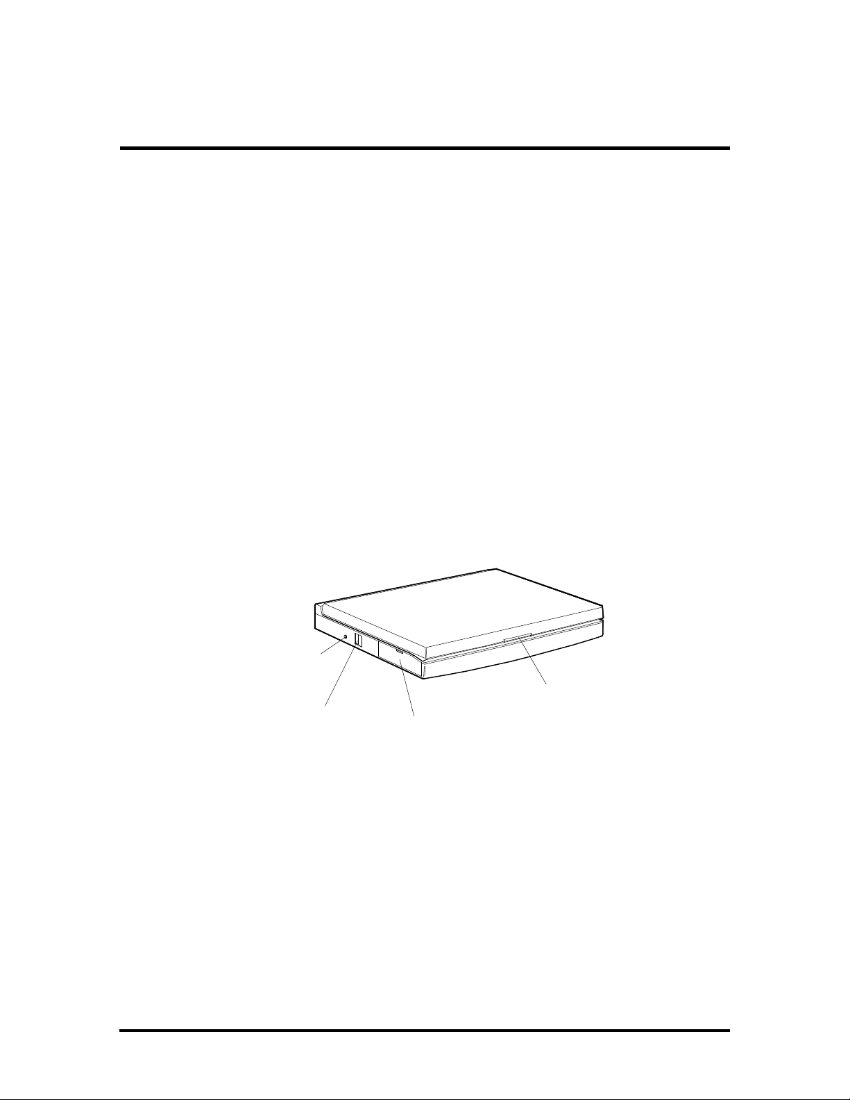
Figure Section 1-1 shows the components on the front and side views of the Versa S.
Reset
Button
LCD
Power
Button
PCMCIA
Slot
Latch
Figure Section 1-1 Versa S Components
The following system upgrades must be completed by authorized customer engineers or an
authorized service center:
n additional memory (up to 12 MB)
n 260-MB hard disk.
System upgrade procedures are described in Section 4, Options.
Page 13
1-2 Technical Information
HARDWARE OVERVIEW
The base unit includes a monochrome or color LCD panel, a 210- or 260-MB hard disk, an
external 1.44-MB diskette drive, a battery pack, and a PS/2 compatible 80-key keyboard. A
81-key keyboard is used for U.K. and Germany.
One memory card slot is available for the addition of a 4- or 8-MB memory card. Two Personal Computer Memory Card International Association (PCMCIA) card slots, supported
by the Cirrus Logic CL-PD6720 PCMCIA chip set, allow for the addition of either two
Type 2 PCMCIA cards or one Type 3 PCMCIA card.
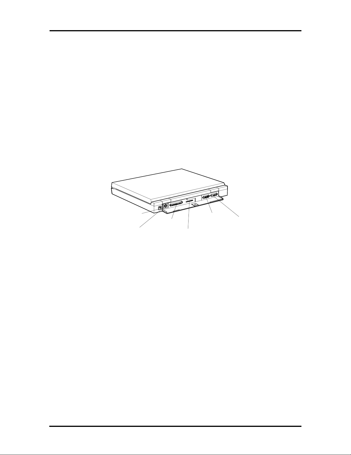
Figure Section 1-2 shows the I/O interface ports on the system's rear panel. These include
one combined 6-pin PS/2-style keyboard and mouse port, one 15-pin Super VGA port, one
9-pin (RS-232C) serial port, one 25-pin enhanced printer (parallel) port, and one 3-pin
power connector port.
Power
Port
Keyboard/
Mouse
Port
Parallel
Port
Diskette
Drive
Port
VGA
Monitor
Port
Serial
Port
Figure Section 1-2 Versa S Series (Rear View)
Liquid Crystal Display (LCD)
The Versa S comes with one of three different LCD panels. Each panel provides a 9.5-inch
viewing area.
n The thin-film transistor (TFT) color LCD has a 640 x 480 resolution, is backlit,
and supports up to 4096 colors.
n The Dualscan Super-Twisted Nematic (DSTN) color LCD has a 640 x 480 reso-
lution, is backlit, and supports up to 256 colors.
n The DSTN monochrome LCD (outside of the U.S. only) has a 640 x 480 resolu-
tion, is backlit, and supports 64 shades of gray.
A VGA port on the system's rear panel allows the user to connect an optional monochrome
or color external display to the system. The computer supports the LCD and external display simultaneously when using a resolution of 640 x 480 or lower.
Page 14
Technical Information 1-3
Power-saving features for controlling the LCD's backlighting include the ROM-based hot
key Fn F5, Fn F6, and Auto Setup power management settings. See Section 2, Setup and
Operation, for information on using these settings. In addition, the automatic LCD status
sense feature conserves the backlight. When the LCD is closed, the backlight shuts off,
saving battery power.
Keyboard
The built-in, 80-key keyboard (U.S.) or 81-key keyboard (UK and Germany) uses the standard QWERTY-key layout. The keyboard provides 12 function keys and 8 cursor control
keys, with an Fn key for ROM-based key functions. The numeric keypad is embedded in the
standard key layout.
Versa SurePoint
The Versa SurePoint™ pointing device performs the functions of a mouse. It is located
between the G, H, and B keys. Pressing the Versa SurePoint in a specific direction moves
the cursor in that direction. The two selection buttons below the keyboard act like the left
and right mouse buttons on a two-button mouse.
The Versa SurePoint is the system's default pointing device unless a PS/2 mouse is installed.
If an external mouse is installed, then the Versa SurePoint is deactivated.
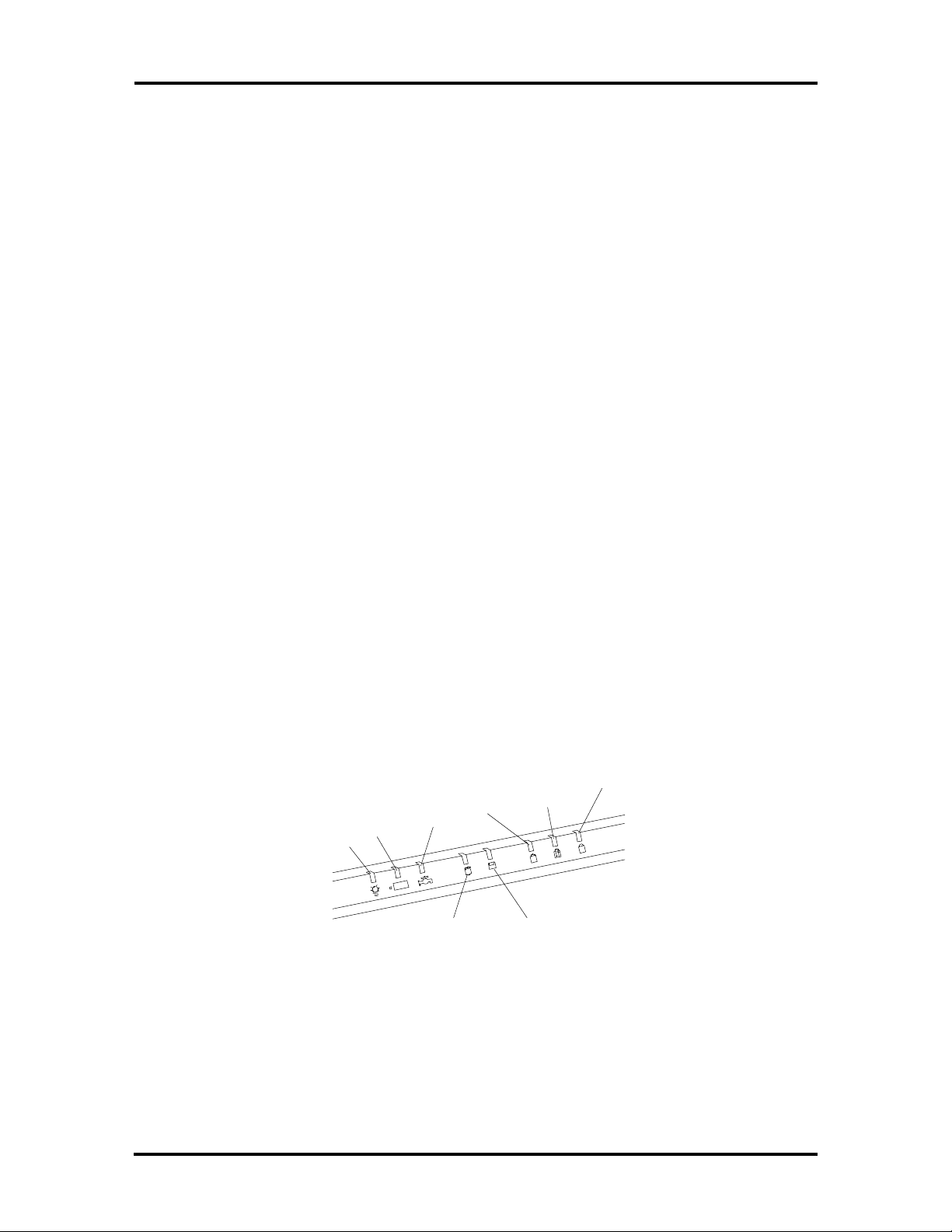
LED Status Bar
The LED status bar contains eight light emitting diodes (LEDs) that light or blink to show
the status of Versa S components. Figure Section 1-3 shows the locations of the LEDs on
the status bar. A description of the LEDs follow.
Num
Power
Charge
Power
Mgmt
Hard Disk
Drive
Caps
Lock
Scroll
Lock
A
Diskette
Drive
Figure Section 1-3 LED Status Bar
Lock
Page 15

1-4 Technical Information
n Power LED — lights yellow or green.
When steady green, the computer is running on AC power.
When steady yellow, the computer is running on battery power and battery
power is sufficient.
When blinking yellow, the computer is running on battery power and battery
power is low.
When off, the computer is in Suspend mode or the computer power is off.
n Charge LED — lights orange.
When lit continuously, the battery is charging.
When blinking orange, the battery has malfunctioned.
When off, no battery is installed, the AC adapter is not attached, or the battery
is fully charged.
n Power Management LED — lights green
When lit continuously, Power Management features are enabled.
When blinking, the system is in Suspend mode.
When off, Power Management features are disabled.
n Hard Disk LED — lights green when the hard disk is being accessed. Avoid
turning off the Versa S when this LED is lit.
n Diskette Drive LED — lights green when a diskette is being accessed.
n Caps Lock LED — lights green when the Caps Lock is in effect.
n Scroll Lock LED — lights green when the scroll lock key is active.
n Num Lock LED — lights green when Num Lock mode is in effect.
Battery
The system uses a nickel metal hydride (NiMH) battery as its transient power source. The
battery pack installs in the compartment at the bottom of the base unit. The battery pack
lasts approximately 2.0 hours under typical operating conditions and recharges in approximately 1.5 hours. A bridge battery is provided as an emergency backup. It backs up memory and system status for up to 5 minutes under Suspend mode.
Page 16
Technical Information 1-5
System Board
The system board is inside the base unit. It contains system components including the CPU,
system memory, and I/O subsystems.
Refer to Table Section 1-1 for a summary of the chipsets supported by the Versa S. For a
list of system board connector descriptions, see Appendix A. System board specifications
are listed in at the end of this section.
Table Section 1-1 Versa S Supported Chipsets
Chip Manufacturer Description Technology
i486SX-33 Intel 33 MHz CPU 208-pin QFP*
i486DX2-50 Intel 50 MHz CPU 208-pin QFP*
PT86C368 PicoPower System Controller 208-pin QFP*
FDC37C665 Standard MicroSystem
Corporation
28F010 Intel 128-KB Flash ROM 32-pin PLCC**
CL-GD6235 Cirrus Logic VGA Controller 208-pin QFP*
80C51SL Intel Keyboard Controller 44-pin QFP*
CL-PD6720-B Cirrus Logic PCMCIA Controller 208-pin QFP*
*QFP: quad flat package
**PLCC: plastic lead chip carrier
CPU
Peripheral Controller 100-pin QFP*
The CPU is an Intel SL Enhanced i486 chip (DX2-50 or SX-33). The CPU controls important functions including power management, direct drive bus interface, and memory
management. It has a 32-bit internal data bus and requires an operating voltage of 3.3 volts.
The CPU’s microprocessor has an internal on-chip cache controller with 8-KB cache memory. The DX2-50's floating point unit (FPU) provides an internal math coprocessor.
Memory
The system board provides 4 MB of standard random access memory (RAM). Optional
memory cards with a value of 4- or 8-MB can be added to increase system memory up to
12 MB.
The system board also provides 128 KB of read-only memory (ROM). The 28F010 flash
ROM contains the system, power management, and video BIOS.
Page 17
1-6 Technical Information
The Versa S supports system and video BIOS shadowing. When shadowing is enabled (default settings), the BIOS is copied from ROM to RAM which speeds up system performance. These settings can be changed in the SCU (see Section 2, Setup and Operation).
Table Section 1-2 shows the system's memory map.
Table Section 1-2 Versa S System
Memory Map
Address Function
FFFFF
|
F0000
|
E8000
|
E0000
|
C8000
|
C0000
System BIOS (shadow) (64 KB)
MAXIMIZER (shadow) (32 KB)
Video BIOS (shadow enabled) (32 KB)
ISA space available
Video BIOS (shadow enabled) (32 KB)
Video Controller
The Cirrus CL-GD6235 video controller integrates a 32-bit local bus video. The system
ships with 512 KB VRAM supporting LCD video modes up to 640 x 480 resolution with
256 colors (color model) or 64 shades of gray (monochrome model).
The system provides a 15-pin D-SUB connector to allow connecting an external display to
the system. The system supports external display video modes up to 1024 x 768 with 16
colors or 800 x 600 x 256 color (non-interlaced). System video also supports simultaneous
external display and LCD viewing. Table Section 1-3 shows the supported Versa S video
modes.
Table Section 1-3 Versa S Video Modes
Mode
(Hex)
12 640 x 480 8 x 16 30 x 30 16/256 25.0 31.5 60.0
58/6A * 800 x 600 8 x 16 100 x 37 16/256 40.0 37.8 60.0
5C * 800 x 600 8 x 16 100 x 37 256/256 40.0 37.9 60.0
5D * 1024 x 768 8 x 16 128 x 48 16 65.0 48.3 60.0
Pixel
Resolution
Character
Size
Columns
/Rows
Colors
(K)
Video
Clock
(MHz)
Horizontal
Freq
(kHz)
Vertical
Freq
(Hz)
Page 18
Technical Information 1-7
5F 640 x 480 8 x 16 80 x 30 256/256 25.0 31.5 60.0
NOTE: * External display only.
Input/Output Controller
The FDC37C665 input/output (I/O) controller provides the following interfaces:
n RS-232C serial port
n parallel (printer) port
n diskette drive
n IDE hard disk.
The user selects between three parallel interface modes using Auto Setup. These include
unidirectional, bidirectional or enhanced. Unidirectional mode sends data output from the
standard ISA port only. Bidirectional mode sends data using the standard ISA port or PS/2
technology. Enhanced mode enables high speed data transmission to occur using either the
unidirectional or bidirectional modes.
Parallel port addresses and interrupts are listed in Table Section 1-4. Pin locations for the
parallel interface are listed in Appendix A.
Table Section 1-4 Parallel Port Addresses and Interrupts
Starting I/O Address Interrupt Level
378h (LPT 1) * IRQ07
278h (LPT 2) IRQ05
3BCh (LPT 3) IRQ07
*Default
The serial port consists of a 16450 compatible serial port controller with a programmable
baud rate within 50/115.2 K bps. See Table Section 1-5 for the available addresses and interrupts.
Table Section 1-5 Serial Port Addresses and Interrupts
Starting I/O Address Interrupt Level
3F8h (COM 1) * IRQ04
2F8h (COM 2) IRQ03
3E8h (COM 3) IRQ04
2E8h (COM 4) IRQ03
Page 19

1-8 Technical Information
*Default
Keyboard Controller
The keyboard controller (80C51SL) supports a PS/2-style keyboard, mouse and security
features such as keyboard hot keys and password. Refer to Appendix A for keyboard interface connector pin assignments.
The input clock cycle is 12 MHz. Data transmits between the controller and the keyboard
through a bidirectional serial interface. The controller receives serial data, checks for parity
errors, converts scan codes, and writes the data to the output buffer.
When data is written to the output buffer, the controller generates an interrupt (IRQ01 or
IRQ12) and requests the CPU to receive the data. The controller automatically adds an
even parity bit to the data sent and waits for a response. The device must acknowledge that
the data was successfully received by sending a response to the controller for each byte of
data received.
PCMCIA Controller (CL-PD6720)
The PCMCIA interface uses a standard Exchangeable Card Architecture (ExCA) connector
allowing the user to choose from an array of optional modem or network cards. The controller interfaces with the ISA bus, PCMCIA card socket and configuration registers to
provide:
n memory address mapping, I/O address mapping
n power management for each PCMCIA card socket, controlled through power and
RESETDRV control registers
n the elimination of interrupt conflicts using interrupt steering.
I/O Addressing
The CPU works in conjunction with I/O devices using I/O mapping. Refer to Table Section
1-6 for hex addresses.
Table Section 1-6 Versa S I/O Address Map
Address (Hex) I/O Device Name
000-00F DMA Controller 1
020-03F Interrupt Controller 1
040-043 Timer 1
048-04B Timer 2
060-064 Keyboard Controller
Page 20
Technical Information 1-9
Table Section 1-6 Versa S I/O Address Map
Address (Hex) I/O Device Name
061 NMI Status
070 NMI Mask
070-076 Real-time Clock
081H-083H DMA Page Register
087H DMA Page Register
089H-08BH DMA Page Register
08FH DMA Page Register
092H Port 92
0C0H-0CEH DMA Channel
0D0H-0DEH DMA Controller 2
0102H Parallel Port Configuration
0278H-027AH LPT2
02F8H-02FFH Serial Controller Port B
0372H-0377H Diskette Drive Controller
0378H-037AH LPT1
03BCH-03BEH LPT3
03F0H-03F5H Diskette Drive Controller Port Status
03F8H-03FFH Serial Controller Port A
0461H Port 461 EISA mode
0C00H Extended System Port 1
0C01H Extended System Port 2
0C02H Extended System Port 3
0C03H Extended System Port 4
0C10H Extended System Port 6
03E0-03E1 PCMCIA
Interrupt Controller
The interrupt controller operates as an interrupt manager for the CPU. The controller receives requests from peripherals and issues interrupt requests to the CPU. Interrupt-level
assignments 0 through 15 are listed in Table Section 1-7, in order of decreasing priority.
Page 21

1-10 Technical Information
Table Section 1-7 Versa S Series Interrupt-Level Assignments
Controller
Master/Slave
Master 0 IRQ00 Counter/Timer 1
Master 1 IRQ01 Keyboard
Master 2 IRQ02 Cascade for 8 to 15
Slave 3 IRQ08 Real-time Clock
Slave 4 IRQ09 VGA
Slave 5 IRQ10 Reserved
Slave 6 IRQ11 Reserved (PCMCIA)
Slave 7 IRQ12 PS/2 Mouse*
Slave 8 IRQ13 Math Coprocessor (built into CPU)
Slave 9 IRQ14 Hard Disk Controller
Slave 10 IRQ15 Reserved
Master 11 IRQ03 COM2, COM4*
Master 12 IRQ04 COM1, COM3*
Master 13 IRQ05 Parallel Port 2
Priority
Name
Device
Master 14 IRQ06 Diskette Drive Controller*
Master 15 IRQ07 Parallel Port 1*
*Industry standard locations
Power Management Overview
The Versa system uses power management features to prolong system battery life.
The CPU (SL Enhanced i486) implements a System Management Interrupt (SMI) function
that works transparently with the operating system and application software. When activated, the processor mode changes to real mode. Unique "SM-RAM" containing power
management software is mapped at address 30000h — 3FFFFh. This activity is inherent to
the system and does not require any adjustment to the operating system or application software.
The power management program is located in ROM at location E8000h — EFFFFh. In onboard DRAM, the software is physically allocated at the same location.
Use the System Configuration Utility to select specific power management options. For information on how to select these options, see Section 3, Power Management.
Page 22
Technical Information 1-11
SPECIFICATIONS
Table Section 1-8 provides a complete list of Versa E series system specifications.
Table Section 1-8 Specifications
Item Specification
Chassis
Size Width: 10.76 in. (276 mm)
Depth: 8.26 inches (212 mm)
Height:
Weight:
Keyboard PS/2 compatible, 80-key standard (U.S.), 81-key
Fn Key for ROM-based functions
Device Slots One internal 2 1/2-inch x 0.75-inch high slot, right
One 3 1/2-inch x 0.75-inch high slot, bottom-access,
— Versa S/50C, S/33C: 1.63 in. (42 mm
— Versa S/33D: )1.52 in. (39 mm)
— Versa S/33M: 1.4 in. (36 mm)
— Versa S/50C: 5.07 lb (2.30 kg)
— Versa S/33C: 4.71 lb (2.14 kg)
— Versa S/33D: 4.71 lb (2.14 kg)
— Versa S/33M: 4.23 lb (1.92 kg)
(Exact weight depends on options)
standard (UK and Germany)
side access, for standard hard disk
for primary battery
One memory slot for optional memory card
Two PCMCIA slots that support up to two optional
cards oriented one on top of the other
Power AC Adapter: Input Voltage: 90 to 240 VAC, 50 or 60
Hz, 1200 mA
DC/DC Adapter: On board
Battery Pack: 12 VDC, 1800 mA
Battery Life: approximately 2 hours under typical
operating conditions
Recharging time: approximately 1.5 hours
Bridge battery: backs up memory contents and
system status for up to 5 minutes under Suspend
mode.
Page 23
1-12 Technical Information
Table Section 1-8 Specifications
Item Specification
System Board
Flash ROM 128 KB: 28F010
System BIOS: 64 KB
Video BIOS: 32 KB
Power Management: 32 KB
I/O Interface Connectors 6-pin PS/2 External Keyboard/mouse Connector
9-pin Serial Connector
15-pin VGA Connector
25-pin Parallel Connector
3-pin DC-In Power Connector
72-pin Internal Memory Connector
44-pin IDE Connector
26-pin External Diskette Drive Connector
CPU SL Enhanced i486 DX2-50 or SX-33
Clock Speed 50 MHz or 33 MHz
Memory
System Memory 4 MB resident on system board
Optional Expandable to 12 MB
Video RAM 512 KB
Cache RAM 8 KB
Display
Monochrome Model Technology: FTN, backlit, monochrome LCD
Resolution: 640 x 480 pixels
Display: 64 shades of gray
Dot Pitch: 0.3 mm
Viewing Area: 9.5 in. screen
Interface: Super VGA
Color Models Technology:
Resolution: 640 x 480 pixels
— Versa S/50C, S/33C: TFT, backlit, color LCD
— Versa S33DDSTN, backlit, color LCD
Page 24
Technical Information 1-13
Table Section 1-8 Specifications
Item Specification
Display:
— Versa S/50C, S/33C: 4096 colors
— Versa S/33D: 256 colors
Dot Pitch: 0.3 mm
Viewing Area: 9.5 in. screen
Interface: Super VGA
Internal Device Support
Diskette Drive External, 3 1/2-inch, 1.44-MB
Hard Disks 210-MB (Versa S/33C, S/33D, S/33M)
260-MB (Versa S/50C)
Controller: IDE controller integrated on hard disk
Software
Standard MS-DOS version 6.2
Windows version 3.1
APM drivers
Mouse drivers
Systemsoft CardSoft PCMCIA
Auxiliary Windows Video Drivers (AWD)
NEC Communications Assistant
Versa S on-line help
Windows and DOS on-line help
Recommended Environment
Operation Temperature: 41_ to 95_F (5_ to 35_C)
Relative Humidity: 20% to 80% (No condensation)
Storage Temperature: -4_ to 104_F (-20_ to 40_C)
Relative Humidity: 10% to 80% (No condensation)
Administrative Compliance
UL 1950
CSA C22.2 No. 220
FCC Class B
TUV EN60950: 1988
C.R.C., c.1374
VDE 0871/6.78
Page 25
Section 2
Setup and Operation
This section provides setup and operation information for the Versa S (including cabling,
power-on verification, and using the System Configuration Utility).
UNPACKING THE SYSTEM
Find an area away from devices that generate strong magnetic fields (electric motors,
transformers, etc.). Place the shipping carton on a sturdy surface and carefully unpack the
system. The carton includes the base unit, external diskette drive, AC adapter, AC power
cable, software diskettes, spare SurePoint caps, and user documentation.
SETUP
Perform the following procedure to set up the Versa S.
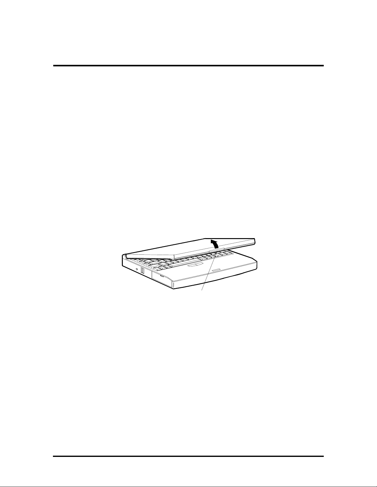
1. Open the LCD panel.
Figure Section 2-1 Opening the LCD Panel
2. Connect the AC adapter cable to the power port on the back of the system.
LCD Latch
Page 26
2-2 Setup and Operation
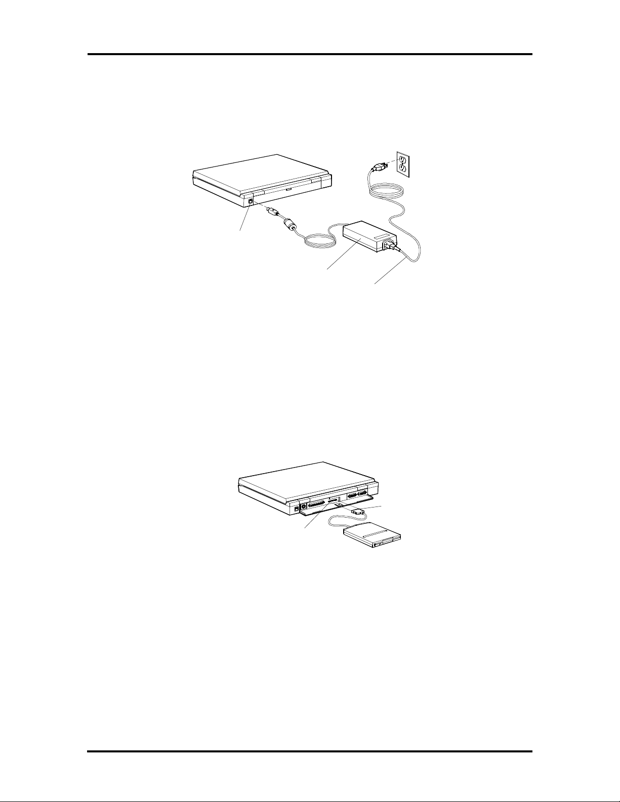
3. Connect one end of the AC power cable to the AC adapter and the other end to a
properly grounded wall outlet.
The LED on the AC adapter and the Charge LED on the system lights.
Figure Section 2-2 Attaching the AC Adapter
Power
Port
AC
Adapter
AC
Power
Cable
4. Connect the diskette drive (optional) to the system as follows:
n Align the diskette drive cable connector with the diskette drive port on the
system.
n Press the connector into the port until it clicks into place.
Cable
Connector
Diskette
Figure Section 2-3 Connecting the Diskette Drive
Drive Port
Page 27
Setup and Operation 2-3
5. Press the power button to turn on the system.
NOTE: If operating on DC power, verify that the
system has a charged battery pack installed.
Power
Button
Figure Section 2-4 Turning on the Versa S
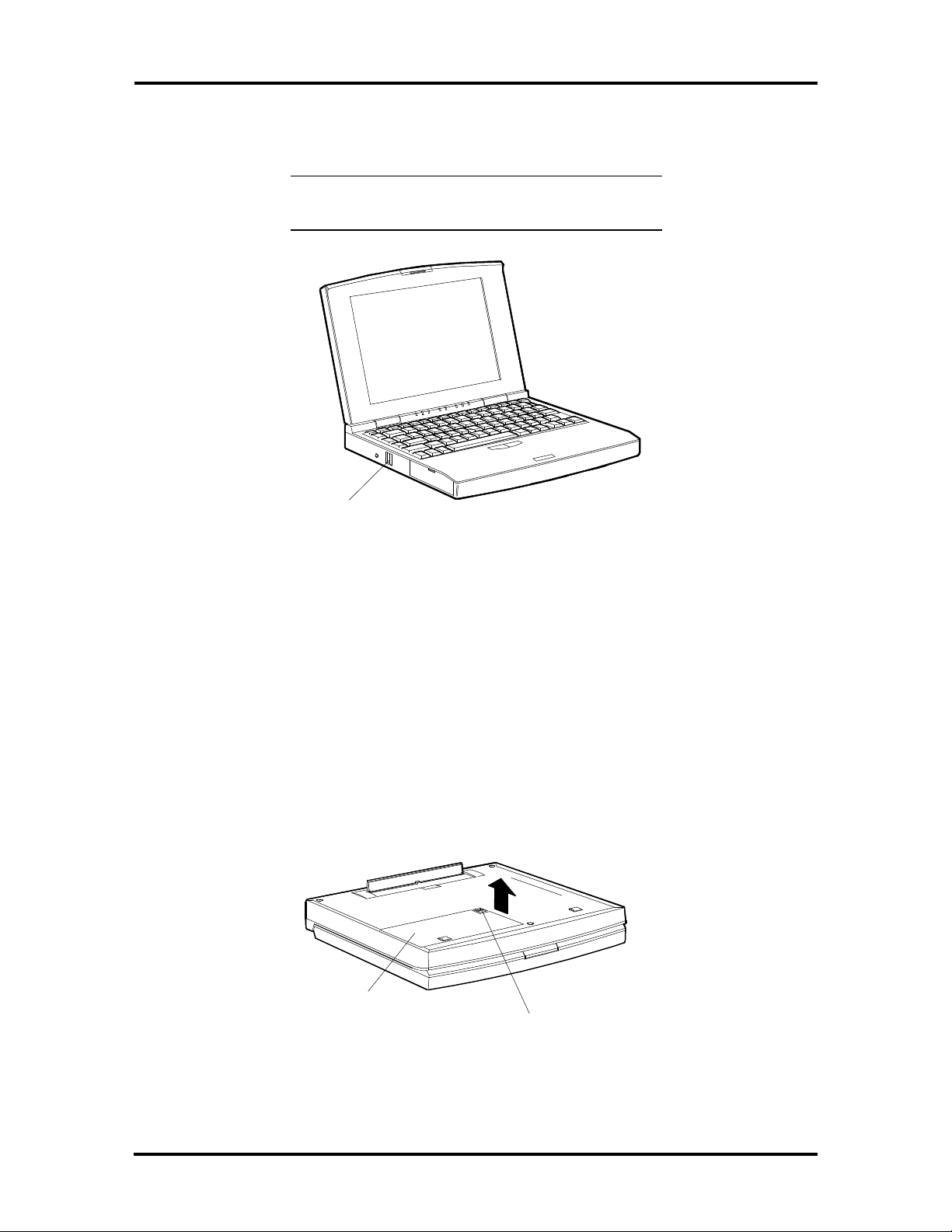
Replacing a Battery Pack
Follow these instructions to replace a battery pack.
1. Close the LCD panel securely. Disconnect any external options.
2. Turn the Versa S upside down.
3. Locate the battery release latch on the bottom of the system and slide it back.
4. Lift up and remove the battery pack.
Battery
Pack
Figure Section 2-5 Removing the Battery Pack
Battery
Release Latch
Page 28
2-4 Setup and Operation
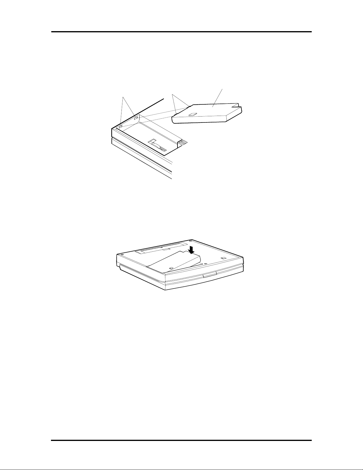
5. Locate the tabs on the end of the new battery pack. Fit the tabs into the grooves
inside the compartment.
Battery
Pack
Grooves
Battery
Pack Tabs
Figure Section 2-6 Locating the Tabs and Grooves
6. Lower the battery pack into the compartment. Press it down until the battery pack
latch clicks and locks the battery in place.
Figure Section 2-7 Inserting the Battery Pack
7. Turn the Versa S right side up and reconnect the external options.
Page 29
Setup and Operation 2-5
OPERATING CONTROLS
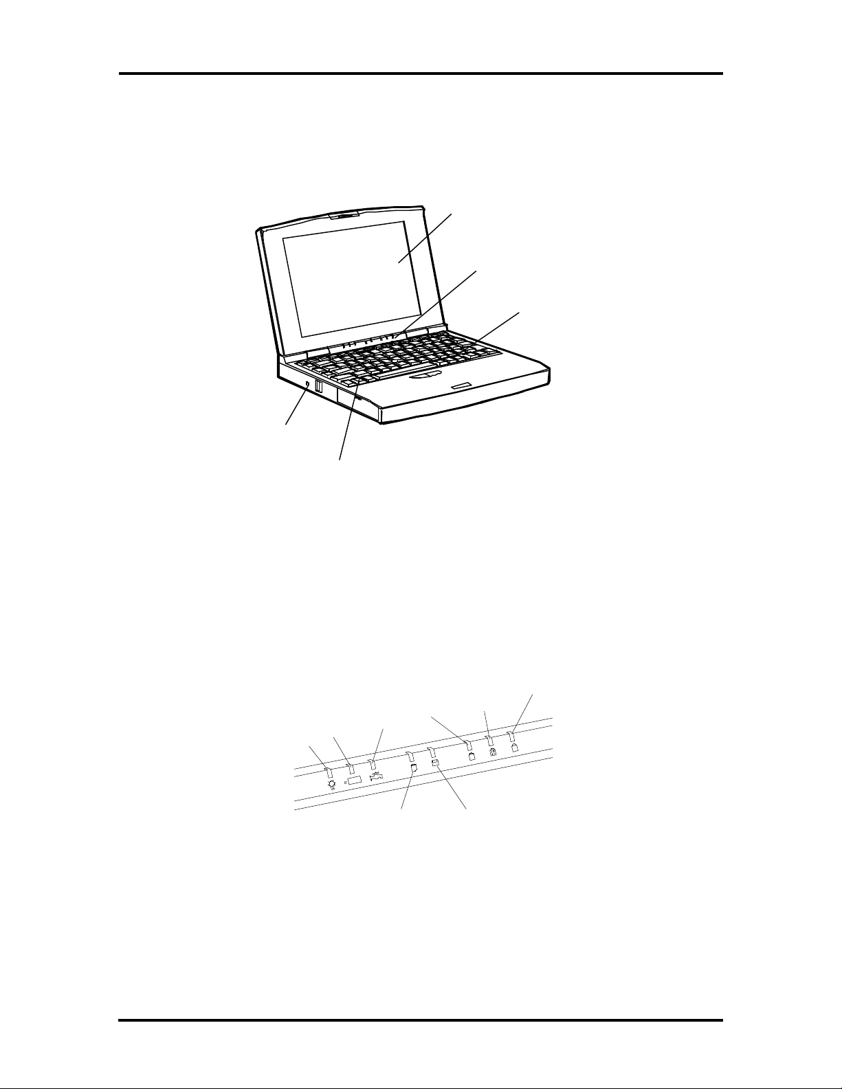
The following section describes system controls. Refer to Figure Section 2-8 to locate system controls and buttons.
LCD
LED Status
Bar
Keyboard
Reset Button
Fn Key
Figure Section 2-8 Control and Button Locations
LED Status Bar
The LED status bar contains eight light emitting diodes (LEDs) that light or blink to show
the status of Versa S components. Figure Section 2-9 identifies the LEDs on the status bar.
A description of the LEDs follow.
Num
Power
Charge
Power
Mgmt
Hard Disk
Drive
Caps
Lock
Scroll
Lock
A
Diskette
Drive
Figure Section 2-9 LED Status Bar
Lock
Page 30

2-6 Setup and Operation
n Power LED — lights yellow or green.
When steady green, the computer is running on AC power.
When steady yellow, the computer is running on battery power and battery
power is sufficient.
When blinking yellow, the computer is running on battery power and battery
power is low.
When off, the computer is in Suspend mode or the computer power is off.
n Charge LED — lights orange.
When lit continuously, the battery is charging.
When blinking orange, the battery has malfunctioned.
When off, no battery is installed, the AC adapter is not attached, or the battery
is fully charged.
n Power Management LED — lights green
When lit continuously, Power Management features are enabled.
When blinking, the system is in Suspend mode.
When off, Power Management features are disabled.
n Hard Disk LED — lights green when the hard disk is being accessed. Avoid
turning off the Versa S when this LED is lit.
n Diskette Drive LED — lights green when a diskette is being accessed.
n Caps Lock LED — lights green when the Caps Lock is in effect.
n Scroll Lock LED — lights green when the scroll lock key is active.
n Num Lock LED — lights green when Num Lock mode is in effect.
Page 31

Setup and Operation 2-7
SurePoint and Selection Buttons
A pointing device that performs the functions of a mouse is located between the G, H, and
B keys. To move the cursor on the screen in a specific direction, press against the SurePoint
in that direction. The two selection buttons below the keyboard act like a left and right
mouse button on a two-button mouse.
Selection
SurePoint
Buttons
Figure Section 2-10 SurePoint and Selection Buttons
Fn Key
The Fn key is used in conjunction with other control keys to perform preprogrammed functions. To use these keys, press and hold the Fn key while pressing another control key. The
Fn and control key combinations provide the following system functions.
n Fn-Esc (the Suspend button) puts the system in Suspend mode. This initiates
power-saving features to conserve energy and battery power.
n Fn-Home (the Break key) stops whatever command is currently executing.
n Fn-Pg Up (the Print Screen key) sends the current screen to the assigned printer.
n Fn-Pg Dn (the Pause key) temporarily stops command execution.
n Fn-End (the Num Lock key) puts the system in Num Lock mode and activates the
embedded keypad.
n Fn-F2 — toggles between three settings: LCD, CRT (external display), and Both.
n Fn-F3 — for monochrome models only. Toggles between normal and reverse text
on the LCD screen. For example, if the screen shows white text on a black background, it changes to black text on white.
n Fn-F4 — increases the display brightness.
Page 32

2-8 Setup and Operation
n Fn-F5 — decreases the display brightness.
NOTE: For longer battery power, decrease the
brightness.
n Fn-F6 — increases the display contrast.
n Fn-F7 — decreases the display contrast.
n Fn-F8 — accesses Power Management setup.
n Fn-F9 — accesses the SCU setup.
n Fn-F11 — toggles Scroll Lock on and off. In some programs, Scroll Lock affects
how the cursor controls work. Pressing a cursor control key scrolls the entire
screen instead of moving the cursor. For example, pressing the up arrow once
moves the entire screen up a line. The cursor stays where it was.
n Fn-F12 — acts as an interrupt key.
Reset Button
The reset button resets the system without turning power off. Push in the reset button using
a pointed object like a straightened paper clip. Use this if the system locks up or fails to respond to keystrokes.
POWER-ON SELF-TEST (POST)
Each time the system is powered on, the system checks the working status of components
through an automatic power-on self-test (POST). The test checks the system configuration
for any discrepancies. One beep means that POST is successful. If any problems in data
transfer or hardware exist, an error message appears.
If the message is an Invalid Configuration message, press F1 to enter the SCU. Press Enter
to review the settings, and make any necessary corrections. For more complete information,
see “Using the SCU” in the following subsection.
If no error messages appear but the system still malfunctions, first check the items in the list
below, then turn to Section 4, Troubleshooting and Repair.
n All cables and power cords are tightly connected.
n The electrical outlet is working.
n The brightness and contrast controls for the display are adjusted properly.
n All options have been properly installed.
Page 33

Setup and Operation 2-9
SYSTEM CONFIGURATION UTILITY
The system uses the System Configuration Utility (SCU) to store information about the
Versa S hardware and software. Use the SCU to perform the following functions:
n set date and time
n change CPU speed
n set a password
n activate power management features
n update system hardware changes.
Accessing the SCU
From the DOS prompt, press Ctrl-Alt-S or Fn-F9 to access the SCU. (Do not access the
utility from Windows.) A screen similar to the following appears.
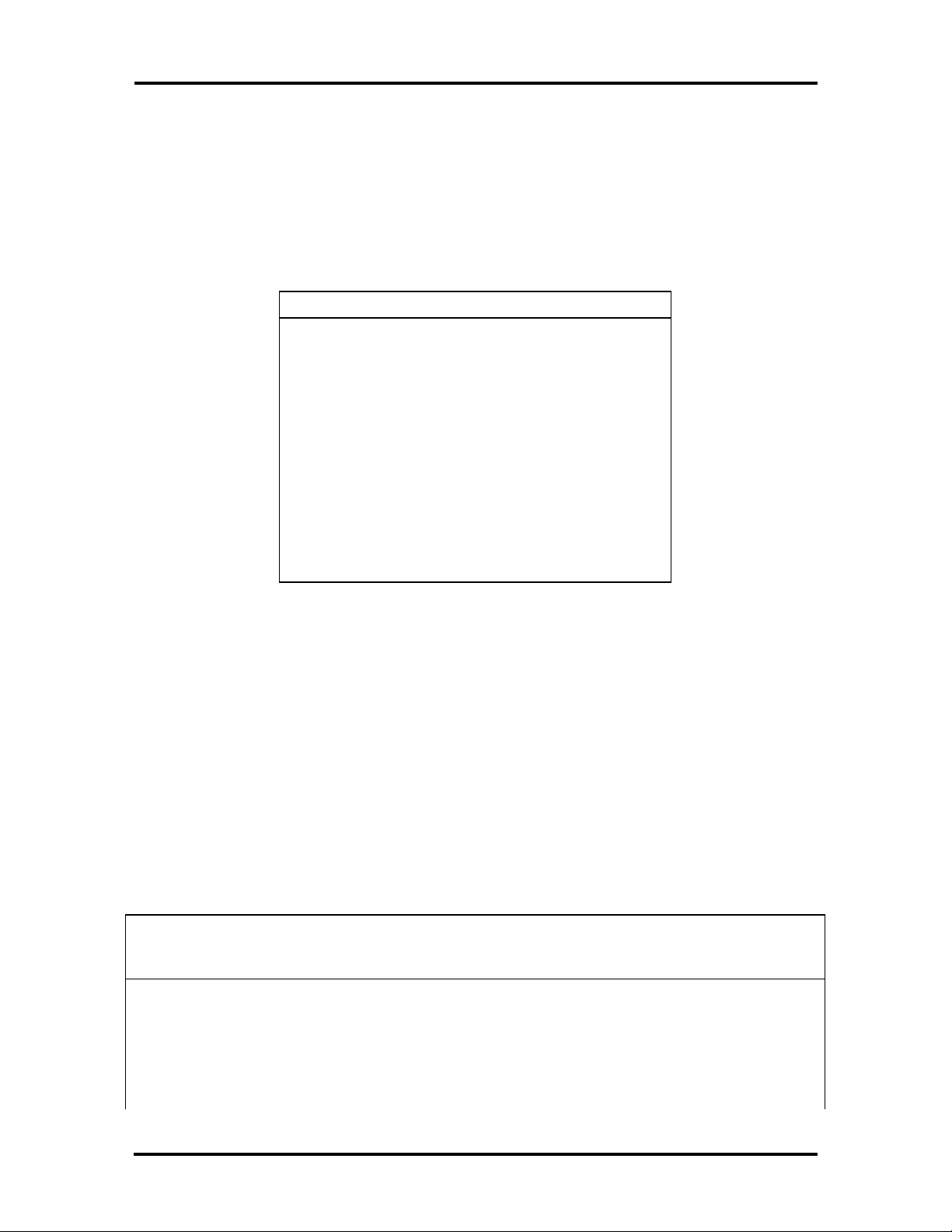
Standard Preferences VGA Memory PowerMgmt Defaults Exit
SystemSoft SCU. Copyright 1983-1994 SystemSoft Corp.
06/07/1994 09:32:02
Memory Peripherals
Base Memory 640KB COM Port A COM1 (3F8h)
Extended Memory 3072KB Stick Pointer Enable
Shadow Memory 128KB LPT Port Address LPT1 (378h)
Reserved Memory 256KB Video Display VGA Display
Total Memory 4096KB Boot Speed Fast Clock
Coprocessor none
Drives
Diskette Drive A 1.44MB
Type Cyls Heads SPT LZONE Precomp Size
Hard Disk Auto
ESC to exit - F10 to save changes
Figure Section 2-11 SCU Main Menu
The Main Menu is made up of the following areas:
n A menu bar at the top of the screen lists the menus.
n The next block shows information about the SCU software, the current date, and
time.
Page 34

2-10 Setup and Operation
n The next three blocks show system settings.
The Memory block displays system memory information.
The Peripherals block shows settings for system peripherals.
The Drives block specifies the diskette drive and hard disk installed.
n The bottom line of the screen shows what key functions are available at that
screen level and what they do.
Using the SCU
Use the following procedure to use the SCU.
1. Use the cursor arrows to highlight the menu selection and press Enter. Suboptions
give three ways to make selections, depending on the option:
n Enter information, as when setting the date or time.
n Toggle between enabled and disabled, as when selecting Num Lock. Press En-
ter to enable a highlighted option. A check appears next to the enabled option.
Press Enter to disable an enabled option. The option is disabled and the check
disappears.
n Some options display a list from which to choose as when selecting a ty-
pematic rate. Use the up and down arrows to highlight the selection and press
Enter.
2. Press Esc to return to the previous menu.
3. Press F10 to save the SCU changes at any time while using the SCU.
SCU Menu Options
Descriptions of menu bar selections and options follow.
Standard
Use the options under Standard to view and modify the following settings.
n Date — Set the date using the format MM/DD/YYYY. The initial setup date is
01/01/1993.
n Time — Set the time using the format HH:MM:SS. The initial setup time is
00:00:00.
Page 35

Setup and Operation 2-11
n COM Port A — Set the Serial Port I/O Address for COM Port A.
COM1 (3F8h) – default setting
COM2 (2F8h)
COM3 (3E8h)
COM4 (2E8h)
Disable
n SurePoint — Enables or disables the SurePoint pointer.
Enable – default setting
Disable
n LPT Port Address — Set the parallel port I/O address.
LPT1 (378h) – default setting
LPT2 (278h)
LPT3 (3BCh)
Disable
n Diskette Drive — Set the diskette drive type for Drive A. It is recommended that
this setting not be changed.
1.44 MB – default setting
720 KB
None
n Hard Disk — Set the hard disk type for Drive C. If replacing the hard disk, see
the documentation that comes with the new drive for hard disk setting information.
Standard
Custom
Auto – default setting
None
Page 36

2-12 Setup and Operation
n Video Display — Set the video display type. Choose from the following selections
if connecting an external monitor.
VGA – default setting
CGA80 Column
CGA40 Column
Monochrome
Preferences
Options available under the Preferences menu are described next.
n Quick Boot — Enable/disable the system to bypass the memory test when the
self-test is performed at start-up.
The default setting is disabled.
n Num Lock — Enable/disable Num Lock mode at system start-up. (The embedded
keypad produces the assigned numbers rather than letters when enabled.) Regardless of this setting, the Num Lock key will enable and disable the Num Lock
mode.
The default setting is disabled.
n Boot Speed — Set the initial CPU speed. When running on battery power, the
slower speed can extend operating time. Choose from the following selections.
Fast Clock – default setting
Slow Clock
n Typematic Rate — Set the speed at which a character repeats when a key is
pressed and held. Choose from the following character per second (cps) values.
30 cps
20 cps
15 cps
10 cps – default setting
6 cps
2 cps
Page 37

Setup and Operation 2-13
n Typematic Delay — Set the delay time between the key press and starting the re-
peat action. Select from the following millisecond (ms) values.
250 ms
500 ms – default setting
750 ms
1000 ms
n Boot Password — Set a password to prevent unauthorized system use. When a
boot password is set, the system requires that the password be entered correctly
before completing the boot cycle.
n Enter a password as follows.
Highlight “Boot Password” and press Enter.
When prompted, type a password that is from 4 to 8 characters long and press
Enter.
When prompted to re-enter the password, enter the password again, and press
Enter.
When the password entry is verified, Boot Password is enabled. No one will
be able to use the system without first entering the password. If the password
is forgotten, call the NEC Technical Support number listed in Chapter 4.
n SCU Password — Set a password to access the SCU. When this option is en-
abled, no one can change system setup parameters without first entering the correct password. This option prevents someone from setting a boot password that
could deny a user access to the Versa S.
n Set an SCU password as follows.
Highlight “SCU Password” and press Enter.
When prompted, type a password that is from 4 to 8 characters long and press
Enter.
When prompted to re-enter the password, enter the password again, and press
Enter.
When the password entry is verified, SCU Password is enabled. No one will
be able to use the SCU without first entering the SCU password.
If the password is forgotten, call the NEC Technical Support number listed in
Chapter 5.
Page 38

2-14 Setup and Operation
n First Boot — Select the drive that the system first looks for the operating system
at system startup.
Drive A – default setting
PCMCIA Card
Drive C
VGA
VGA submenu option is described next.
n Display Mode — Select and activate the display mode. To use an external moni-
tor with the Versa S, select "Both."
Both
LCD – default setting
CRT
Memory
Memory setup features enable and disable cache memory.
n Cache Enable —Enabling this feature can speed up some application processing.
The cache is enabled at the factory.
To disable cache memory, highlight the option and press Enter.
Power Management
For details about power management features and settings, see Section 3.
Default Setup
Sets default values for all setup entries. Defaults set for the Standard menu are as follows:
n Date — 01/01/1993 (default setting)
n Time — 00:00:00 (default setting)
n COM Port A — COM1 (3F8h)
n SurePoint — Enable
n LPT Port Address — LPT1 (378h)
Page 39

n Diskette Drive — 1.44 MB; diskette drive
n Hard Disk — Auto
n Video Display — VGA display
Defaults set for the Preferences menu are as follows.
n Quick Boot — Disabled; performs memory test at start-up
n Num Lock — Disabled; off at start-up
n Boot Speed — Fast clock
n Typematic Rate — 10 cps
n Typematic Delay — 500 ms
n Boot Password — Disabled
n SCU Password — Disabled
Setup and Operation 2-15
n First Boot — Drive A
The default setting in the VGA submenu is as follows.
n Display Mode — LCD
The default setting in the Memory submenu is as follows.
n Cache Enable — Enabled.
Exit
Highlight Exit and press Enter to exit the SCU.
n If no changes were made, the following system message appears:
ESC to exit now
Any other key to continue
Press Esc to exit the utility. Press any other key to continue making SCU selections.
Page 40

2-16 Setup and Operation
n If any of the SCU settings were changed, the following screen message appears.
Do you wish to save your changes?
ESC to exit – Enter to save and exit
Any other key to continue
If Esc is pressed, the system does not save any changes and exits the SCU.
The system does not reboot.
If Enter is pressed, the system writes the new setup values to backup battery
memory, then exits the program. The system reboots.
If any other key is pressed, the system returns to the SCU Main Menu.
Page 41

Section 3
Power Management
Power Management is a set of power-saving features built into the Versa S. These features
conserve energy, maximize the life of the battery pack and LCD backlight, and protect
against data loss due to low battery power.
Versa S has two programs that work together to provide power management capabilities.
n Power Management Utility — accessed through the SCU
n Advanced Power Management (APM) — accessed through MS-DOS or Win-
dows.
This section describes the Power Management Utility and APM. It also provides guidelines
for extending battery life for the Versa S.
POWER MANAGEMENT UTILITY
The Power Management utility provides settings for various power-saving features. They
include:
n enable or disable Power Management
n set the system to go into Suspend mode automatically when closing the LCD
panel
n specify time-outs for the CPU, LCD, and hard disk before going into Suspend
mode
n stipulate many other power-saving features.
Accessing the Power Management Utility
Access Power Management with one of the following methods. (Do not try to access this
utility from Windows.)
n Use the function key combination Fn-F8 to go directly into Power Management.
n From the DOS prompt, press Ctrl-Alt-S to access the SCU Main menu. From the
menu bar, highlight “Power Mgmt” and press Enter.
Page 42

3-2 Power Management
A screen similar to the following appears.
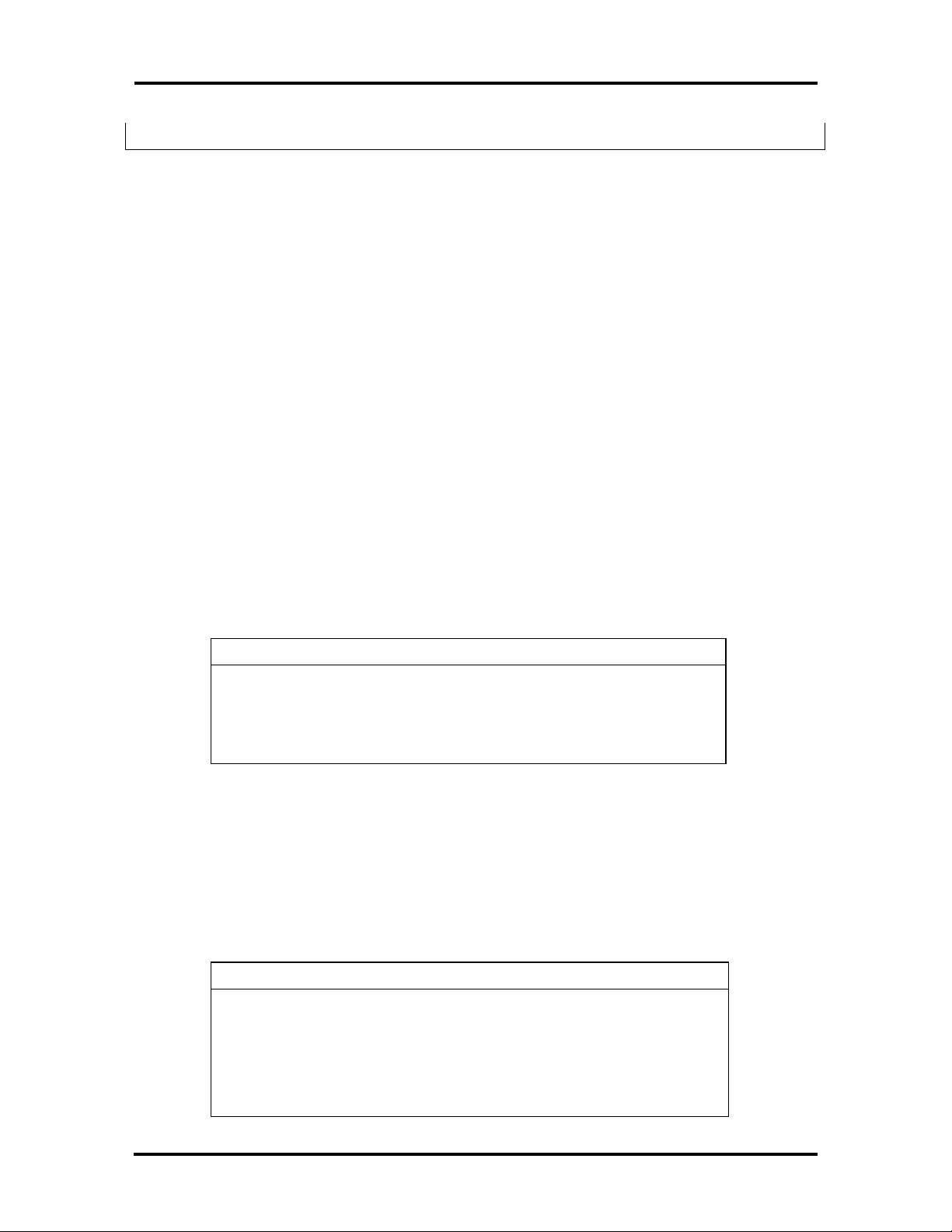
Controls System Device Defaults Exit
SystemSoft MAXIMIZER(TM) for 80486/86C268 Version 0.3(2305-02]
Copyright 1990-1994 SystemSoft Corp. All Rights Reserved
Controls System Options
Power Savings: Always CPU Idle: Disable
LCD Brightness Control: Full Global Standby: Disable
Battery Low: Warn Only Auto Suspend: Disable
Alarm Resume: Disable Video Monitoring: Disable
Cover Switch: Suspend
Devices
Video: Always On
Hard Disk: Always On
ESC to exit - F10 to save changes
Figure Section 3-1 Power Management Menu
To make selections in Power Management, use the keyboard keys as follows:
1. Use the right and left cursor arrows to highlight the menu selection.
2. Press Enter.
3. In the submenu, use the up and down cursor arrows to highlight a suboption.
4. Press Enter. Suboptions provide two ways to make a selection:
n Some options toggle between being enabled and disabled. Press Enter to
enable a highlighted option. A check appears next to the enabled option.
Press Enter to disable enabled options. The check disappears and the option
is disabled.
n Some options display a list from which to choose. Use the up and down
arrows to highlight the desired choice and press Enter.
5. Press Esc to return to the previous menu.
6. Press F10 to save the changes at any time.
Page 43

Power Management 3-3
Menu Options
Descriptions of the menu bar selections and options follow.
Controls
Use the Controls menu to enable and disable the following features.
n Power Saving — This option specifies when power saving features are enabled.
Select from the following choices.
Always – enables Power Management when the system is running on either
battery or AC power.
Battery – enables Power Management when the system is running on battery
power (default setting).
Disable – disables Power Management.
n LCD Bright Ctrl — Specifies the initial brightness setting for the LCD panel.
Full – default setting when running on AC power
Standard – default setting when running on battery power
n Battery Low — Enabling Battery Low directs the system to enter Suspend mode
when it detects low battery power.
n Modem Ring Resume — When enabled, this option specifies that if the system
detects a modem ring, it returns to normal operation mode if it is in a powersaving mode.
n Alarm Resume — When enabled, this option directs the system to exit power-
saving modes at a specified time. Once enabled, the system asks for a time to resume operation mode.
Highlight Alarm Resume and press Enter to enable the option. Enter the time in
the xx:xx (hour:minute) format, using a 24-hour clock.
n Cover Close Switch — This option directs the Versa S to do one of the following
when the LCD panel is closed. It either turns off just the LCD panel or puts the
entire system in Suspend mode.
LCD On/Off (turns off just the LCD panel)
Suspend – default setting (puts the Versa S into Suspend mode)
n Beeper On/Off — This option enables and disables the system’s internal speaker.
The default setting is Enabled.
Page 44

3-4 Power Management
System Options
System Options menu specifies how long the system is inactive before initiating powersaving features and going into Suspend mode. Use the System Options menu to enable and
disable the following features.
n CPU Idle — Set how long the system is idle before slowing the rate of the CPU
speed. Choices are as follows.
4 sec (default setting)
8 sec
16 sec
Disable
n Global Standby — Specify how long the system is idle before entering Global
Standby mode. Global Standby powers down the specified devices and slows the
CPU clock speed.
1 Minute (Min)
2 Min
4 Min (default setting)
6 Min
8 Min
12 Min
16 Min
Disable
n Auto Suspend — Define how long the system is inactive before automatically
going into Suspend mode.
1 Min (default setting)
5 Min
10 Min
20 Min
30 Min
40 Min
Page 45

Power Management 3-5
60 Mine
Disable
n Video Monitoring — Specify whether Power Management monitors video activ-
ity as it relates to going into Suspend mode. Disabling video monitoring is useful
for applications that have something happening on the screen constantly. For example, a changing clock on the screen can keep the system from initiating power
saving features even though the system is not in use.
Choose from the following selections.
Enable: ON
Disable: OFF (default setting)
Device Setup
The options under Device Setup specify how long a device is inactive before power-saving
is activated.
n Video — Specify how long the monitor waits for system inactivity before putting
the LCD or CRT into Video Standby mode. The screen goes blank in Video
Standby. This mode is most effective in LCD mode, because it turns off the panel
backlight.
1 Min
2 Min (default setting)
4 Min
6 Min
8 Min
12 Min
16 Min
Always On
n Hard Disk — Set how long the hard disk waits for access before going into Hard
Disk Standby mode. Hard Disk Standby mode slows the hard disk speed.
1 Min
2 Min (default setting)
4 Min
Page 46

3-6 Power Management
6 Min
8 Min
12 Min
16 Min
Always On
Default Setup
Highlight Default Setup and press Enter to reset Power Management options to their default settings.
Exit
Highlight Exit to exit the Power Management Utility screen.
n Press Enter. If changes were made, the system displays the following message.
Do you wish to save your changes?
ESC to exit – ENTER to save and exit
Any other key to continue
n If no changes were made, the system displays the following message.
ESC to exit now
Any other key to continue
Follow the appropriate instructions.
APM PROGRAM
Advanced Power Management conserves power through features that are specified by the
APM program. APM settings are already specified in the system. When power management
is enabled through the SCU, the system retrieves the settings specified in APM and initiates
them after the defined timeouts. If the settings are changed, either through DOS or Windows, the new settings are initiated. (See the MS-DOS and Windows User’s Guide for details.)
The following subsections describe the APM features.
Page 47

Power Management 3-7
Hardware Power Management
Specific hardware power management features include the following.
n Clock stretching — APM reduces the CPU speed without adding a wait state
when a 0.5-cycle wait state is needed in case of DRAM access.
n Quiet bus — APM inhibits all signals in the AT Bus except the AT bus cycle. This
function saves energy by reducing the number of unnecessary charges and discharges.
n Power-saving devices — APM puts devices that have power-saving features into
Standby mode when they are not active.
System Power Management
System power management features include the following.
n APM Idle — APM uses an Idle Detector to sense system inactivity. (The detector
does not work with some applications.)
n CPU Standby — When enabled, APM slows the CPU clock speed to 3.125 MHz
if no system activity is detected for the specified timeout. Once system activity is
detected, the CPU clock speed returns to normal.
NOTE: System activity includes diskette drive
and hard disk access, keyboard activity, COM
port and LPT port input/output.
n Global Standby — When enabled, global standby puts all specified devices into
Standby mode and slows the CPU clock speed to 3.125 MHz after the specified
timeouts. Once system activity is detected, the system returns to normal operation
mode.
n Auto Suspend — When enabled, Auto Suspend puts the system into Suspend
mode after the specified timeout elapses.
Page 48

3-8 Power Management
Device Status
The following table shows the status of system devices in Auto Suspend mode.
Table Section 3-1 Status of Devices in Auto Suspend
Mode
Device Status
PT86C368 Suspend
Main/expansion memory Slow refresh
82C206 Active
32-KHz Oscillator Active
80C51SL Standby
VGA Controller Standby
Video Memory Slow Refresh
Power SW Circuit Active
NOTE: Suspend/Resume does not work with
operating systems that employ protected modes
(such as OS/2 and UNIX). To use a protectedmode operating system, disable power saving.
The following table shows the status of devices when the system is in the listed power-saving mode.
Table Section 3-2 Status of Devices in Power Saving
Mode
Device
CPU 1/2 maximum 1/2 maximum Off
Evergreen/PINE On On Suspend Mode
8C206 On On Suspend Mode
FDC37C665 On On Off
Main Memory Normal Normal Slow Refresh
ROM On On Off
CPU
Standby
Global
Standby
Suspend
80C51SL Idle Idle Suspend Mode
Internal keyboard Active Active Any-Key Resume
Page 49

Power Management 3-9
Table Section 3-2 Status of Devices in Power Saving
Mode
Device
External keyboard Active Active Off
Cirrus VGA On Standby Slow Refresh
LCD (Display and
Backlight)
SurePoint On On Off
PS/2-Style Mouse On On Off
Diskette Drive On Standby Off
Hard Disk On Standby Off
Serial Port Buffer On On Off
CPU
Standby
On Off Off
Global
Standby
Suspend
EXTENDING BATTERY LIFE
Use the following guidelines to reduce power consumption and maximize battery life. These
guidelines work with AC power as well as battery power. (Some of these features must be
set up through the Power Management utility. See the preceding sections in this section for
details.)
n Turn off the system when not using it.
n Adjust the LCD brightness and contrast to the lowest settings that are comfort-
able for viewing.
n Use the Power Management utility to shorten the timeouts set for powering down
the system.
n If leaving the computer for a short time but plan to return soon, put the system in
Suspend mode. Do so as follows:
Press the Suspend button (Fn-Esc).
Close the LCD panel to automatically put the system into Suspend mode.
(Selected through Power Management.)
Page 50

Section 4
Options
This section provides installation procedures for adding the following options:
n PCMCIA cards
n External devices:
Parallel interface devices, (parallel printer)
Serial interface devices, (modem or serial printer)
Keyboard
Mouse
Monitor.
n Internal Upgrades:
Memory module
Hard disk.
NOTE: Some options described here may not
be available outside of the U.S. Contact an
authorized NEC dealer for specific information.
PCMCIA CARDS
The Versa S has two PCMCIA card slots for attaching options like a fax/modem, Local
Area Network (LAN) card, additional memory, and extra hard disk storage.
The Versa S can handle Type I, II, or III PCMCIA cards and card combinations.
n Up to two Type I cards
n Up to two Type II cards
n One each, Type I and Type II card
n One Type III card.
See the Versa Series PCMCIA User’s Guide for information about installing cards, card
types, and their uses.
Page 51

4-2 Options
The PCMCIA slots are located on the left side of the Versa S. Slot 0 is the bottom slot; slot
1 is the top slot.
PCMCIA
Card Slot
Figure Section 4-1 PCMCIA Card Slots
Modem Card Connection
A telephone cable with modular (RJ11) connectors on both ends is required to connect a
modem card to a telephone system. These cables and other accessories can be purchased
wherever telephones are sold.
NOTE: PCMCIA modem connector adapters
vary. See the guide that came with the modem
card for specific setup information.
Page 52

Follow these steps to connect the system to a phone line.
1. Install the PCMCIA modem card in one of the slots in the Versa S. (See the Versa
Series PCMCIA User’s Guide for details about installation.)
PCMCIA
Card
Options 4-3
PCMCIA
Card Slot
Figure Section 4-2 Installing the Modem Card
2. Connect the modem adapter to the modem card.
Modem
Adapter
Figure Section 4-3 Connecting the Adapter
3. Plug one of the modular telephone cable connectors into the jack on the modem
adapter.
Page 53

4-4 Options
4. Proceed as follows:
n To connect the modem directly to a wall outlet, plug the other end of the
n To connect the modem and telephone to the same wall jack, go to step 5. (To
phone cable into a telephone jack in the wall.
Attaching the modem is complete.
connect both the modem and telephone, a dual-RJ11 connector is needed.)
Telephone
Jack
Figure Section 4-4 Telephone Line Connection
5. Plug the other end of the phone cable into the single jack on a dual-RJ11 connec-
tor.
6. Unplug the telephone cable from the wall. Plug the cable into one of the remaining
jacks on the dual-RJ11 connector.
7. Connect another telephone cable to the second jack on the dual-RJ11 connector
and to the wall jack.
NOTE: An international telephone adapter may
be required outside the U.S. and Canada.
Page 54

Options 4-5
Dual RJ11
Connector
Figure Section 4-5 Modem and Telephone Connection
EXTERNAL DEVICES
This section provides installation procedures for connecting external devices to the Versa S.
Before connecting the device, set it up using the instructions that come with the device.
Parallel Devices
To install a printer or other parallel device, a cable with a 25-pin male connector is required.
For most parallel printers, one end of the cable should have a 36-pin Centronics® connector.
Follow these steps to attach a parallel device to the Versa S.
1. Open the port cover on the back of the Versa S and locate the parallel port.
2. Connect the 25-pin cable connector to the parallel port.
3. Secure the connection with the screws provided.
4. Connect the 36-pin connector to the port on the device. Lock the connector clips.
5. Connect the power cable to the printer and a properly grounded wall outlet.
Connector
Clips
Screws
Figure Section 4-6 Connecting a Parallel Device
Page 55

4-6 Options
Serial Devices
To install a serial device, like a printer or an external modem, a cable with a 9-pin female
connector for the system is required. Follow these steps to attach a serial device to the
Versa S.
1. Check that power to both Versa S and device is off.
2. Open the port cover on the back of the system and locate the serial port.
3. Connect the device cable connector to the serial port. Secure the connection with
the screws provided.
4. Align and connect the 9-pin connector to the correct port on the serial device. Se-
cure the connection with the screws provided.
5. Connect the power cable to the serial device and a properly grounded wall outlet.
Serial
Port
Screws
Figure Section 4-7 Attaching a Serial Device
Keyboard
Follow these steps to connect an external keyboard to the system.
1. Turn off the Versa S. Do not leave it in Suspend or Standby mode.
CAUTION: Make sure the system power is off
whenever attaching or removing the keyboard.
Failure to do so can damage the keyboard.
2. Open the cover on the back of the Versa S and locate the external keyboard port.
Page 56

Options 4-7
3. Connect the keyboard cable connector to the port.
Keyboard
Connector
Keyboard/
Mouse Port
Figure Section 4-8 Attaching the External Keyboard
NOTE: The Fn-Esc or Fn-F9 key combination
cannot be used from the external keyboard.
Mouse
The software needed to recognize the external mouse in Windows and DOS programs is already installed in the system. Connect an external mouse to the Versa S as follows:
1. Turn off the Versa S. Do not leave it in Suspend or Standby mode.
CAUTION: Make sure the Versa power is off
whenever adding or removing the mouse. Otherwise, the system fails to recognize the mouse.
2. Open the port cover on the back of the Versa S and locate the external keyboard
connector.
Page 57

4-8 Options
3. Connect the mouse cable connector to the port.
4. Turn on the system and start the SCU.
5. Under the Standard menu, locate the SurePoint option and disable it.
Mouse
Connector
Keyboard/
Mouse Port
Figure Section 4-9 Connecting the Mouse
NOTE: The SurePoint or its selection buttons
cannot be used when attaching an external
mouse.
6. Save the changes when exiting the SCU. The system automatically recognizes the
external mouse.
Monitor
Before attaching the external monitor, change the VGA setting through the SCU or the Fn-
F2 function key. To use the monitor, the VGA option should be either CRT or Both.
If the setting is LCD, the Versa S does not recognize or activate the external monitor. See
Chapter 2 for details about using the SCU.
NOTE: Use Fn-F2 to toggle between LCD,
CRT, and Both.
Follow these steps to connect an external monitor to the Versa S.
1. Turn off the power to both the external monitor and the Versa S. Do not leave the
notebook in Suspend mode. The system will not recognize the newly connected
monitor when returning to the operating mode.
Page 58

Options 4-9
2. Slide the cover latch down and open the port cover on the back of the Versa S.
3. Connect the 15-pin cable connector to the monitor port on the Versa S. Attach
and secure the connection with the screws provided.
Screws
VGA Port
Monitor Cable
Figure Section 4-10 Connecting the External Monitor
4. Plug the monitor power cable into a properly grounded wall outlet.
Connector
5. Turn on power to the monitor.
NOTE: Whenever using an external monitor
with the Versa S, turn on the monitor first. Otherwise, the notebook does not recognize the external monitor type.
6. Turn on power to the Versa S.
INTERNAL UPGRADES
Internal upgrades to the Versa S include expanding memory and upgrading the hard disk.
Performing these upgrades require the following basic procedures:
n Moving the keyboard out of the way.
n Performing the upgrade.
n Replacing the keyboard.
n Running SCU to set up the new system configuration.
This section describes each process in detail.
Page 59

Section 4
Moving the Keyboard
Follow these steps to move the keyboard out of the way before installing memory or replacing the hard disk.
1. Unplug the Versa S system and any peripheral devices connected to it.
2. Turn off system power.
NOTE: Do not leave the system in Suspend or
Standby mode when installing internal options.
3. Open the LCD panel until it lies flat.
4. Locate the plastic retainer across the top of the keyboard.
5. Find the groove between the F7 and F8 function keys. Insert a thin pointed object
(like the tip of a small screwdriver) under the retainer.
Groove between
F7 and and F8 Keys
Retainer
Figure Section 4-1 Locating the Retainer
Flip the retainer up to remove it. Put it in a safe place. The keyboard springs up a
ways when the retainer is removed.
Retainer
Page 60

4-10 Options
6. Move the keyboard out of the way as follows:
n Gently lift the back of the keyboard up no more that 1.5 inches.
n Pull the keyboard back slightly to release the front tabs from under the chassis.
n Once the keyboard clears the chassis, gently turn the keyboard over, moving
the keys towards the LCD panel.
Figure Section 4-2 Removing the Retainer
Keyboard
Figure Section 4-3 Lifting the Keyboard
n Rest the keyboard on the LCD panel.
Keyboard
(bottom)
Figure Section 4-4 Leaning the Keyboard against the LCD
7. Proceed as follows:
n To install a memory module, go to “Upgrading Memory.”
n To install a new hard disk, go to “Upgrading the Hard Disk.”
Page 61

Options 4-11
Upgrading Memory
The Versa S comes with 4 megabytes (MB) of random access memory (RAM) installed on
the system board. Memory can be increased up to a maximum of 12 MB, by installing one
of the following memory modules.
n 4-MB memory module
n 8-MB memory module.
Install the memory module as follows.
1. Move the keyboard out of the way (follow the instructions in the preceding sec-
tion).
2. Locate the memory module socket on the system board.
Memory Module
Socket
Figure Section 4-5 Locating the Memory Module Socket
3. Align the memory module connector with the socket on the system board.
Page 62

4-12 Options
4. Press the memory module gently to ensure a secure connection.
Figure Section 4-6 Installing the Module
5. If there is nothing else to be installed, go to “Replacing the Keyboard” to continue
with the upgrade.
Upgrading the Hard Disk
Upgrade the hard disk as follows:
1. Move the keyboard out of the way following the instructions in “Moving the Key-
board.”
2. Locate the hard disk.
Figure Section 4-7 Locating the Hard Disk
Shield
Hard
Disk
Page 63

Options 4-13
3. Locate and remove the screw that secures the protective shield and the drive.
CAUTION: Do not use a magnetic screwdriver
when removing the screw. Doing so can erase
the data on the hard disk.
Shield
Screw
Figure Section 4-8 Removing the Screw
4. Lift the shield out of the system.
5. Disconnect the hard disk from its connectors and slide it out of the system.
Hard Disk
Figure Section 4-9 Removing the Hard Disk
6. Lower the new drive into the system, align the drive connectors with those in the
system, and slide the drive into position.
Page 64

4-14 Options
7. Firmly press the drive towards the connectors until the attachment is secure.
8. Lower the protective shield over the hard disk.
9. Replace the screw that secures the drive and shield.
Hard Disk
Figure Section 4-10 Installing the Hard Disk
CAUTION: Do not use a magnetic screwdriver
to replace the screw. Doing so can erase the data
on the hard disk.
10. If there is nothing else to be installed, go to the next section, “Replacing the
Keyboard" to continue with the upgrade.
Replacing the Keyboard
Replace the Versa S keyboard as follows:
1. Turn the keyboard over and align it so it is parallel with the system.
2. Lower the tabs on the front of the keyboard under the edge of the chassis.
Tabs
Keyboard
Figure Section 4-11 Positioning the Keyboard
Page 65

Options 4-15
3. Lower the keyboard back into position.
CAUTION: Be sure to tuck the keyboard cables
under the keyboard.
4. Re-insert the plastic retainer as follows:
n Locate the tabs on the retainer.
n Align the tabs with the grooves in the system.
n Fit the tabs into the grooves. The retainer will curve up slightly in the middle.
n Once the tabs are fitted into the grooves, press down on the center of the re-
tainer until it snaps into place.
Tabs
Figure Section 4-12 Inserting the Retainer
5. Reconnect any external options that were disconnected before starting the instal-
Retainer
lation.
6. To complete the software part of the installation, continue with the next section,
“Running Setup.”
Running Setup
The first time starting the Versa S after installing the memory module or hard disk, an error
message appears. Proceed as follows.
Memory Modules
If upgrading memory, follow these steps.
1. Press Ctrl-Alt-S or Fn-F9 to start the SCU. The Versa S automatically looks at
the new RAM size.
Page 66

4-16 Options
2. Press F10 or Fn-F9 to save the amount of memory. Once the information is
saved, the system automatically recognizes the additional memory.
Hard Disk
If replacing the hard disk, follow these steps.
1. Press Ctrl-Alt-S or Fn-F9 to start the SCU. Select Standard, then HDD, then
Auto to read the new hard disk parameters.
2. Press F10 to save the new drive parameters. Once the information is saved, the
system automatically recognizes the new drive.
Page 67

Section 5
Troubleshooting and Repair
This section provides information on maintaining, troubleshooting, and repairing the
Versa S series sub-notebooks. NEC service and information telephone numbers are listed in
Table Section 5-1.
Table Section 5-1 NEC Service and Information Telephone Numbers
Service Call
To order NEC spare parts In the U.S., call 1 (800) 632-4525
To order options in the U.S. Local Sales Office
To access the NEC Electronic Bulletin Board
System (BBS)
To down load files - provides software drivers
and the latest ROM BIOS for flash ROM
computer systems
NEC Service In the U.S., call 1(800)632-4525
Listen to the automated attendant and select the appropriate menu
to reach one of the following departments.
Information Center - literature, dealer locations, sales leads, response to ads
NASC (National Authorized Service Centers)
Administration - new dealer service authorization/warranty claims
NSRC (National Service Response Center) - questions other than products, spare parts or
technical support
Service Contracts
TAC (Technical Assistance Center) - technical support for NASC and NEC sales
representatives only
TSC (Technical Support Center) - technical support for everyone else
Laptops/Notebooks (Versa/ProSpeed/UltraLite)
Desktop/Tower Computers (Ready/Image/PowerMate/BusinessMate/Express)
Printers (Silentwriter/Colormate/Pinwriter)
1(508) 635-4706 (see "BIOS Update Utility" in
Section 2)
1(508) 635-4706 (see "BIOS Update Utility" in
Section 2)
FastFacts™ - automated service that sends
the latest information about NEC products to
your fax machine 24 hours a day
Use FastFacts to obtain Technical Information
Bulletins.
Canadian Inquires 1(416) 795-3554
In the U.S., call 1(800) 366-0476
Outside the U.S., call 1(708) 860-9500, Ext. 2621
Page 68

5-2 Troubleshooting and Repair
MAINTENANCE
This subsection contains general information for cleaning and checking the system unit,
keyboard, and LCD.
The system unit, keyboard, and LCD require cleaning and checking at least once a year, and
more often if operating in a dusty environment. No other scheduled maintenance or lubrication is required.
WARNING: Remove the battery and disconnect
the AC adapter before performing any maintenance. Voltage is present inside the system even
after the power button is off.
Cleaning
Use the following procedure for cleaning the system.
1. Power off the system, unplug all power cables, and remove the battery pack.
2. Wipe the outside of the system unit, keyboard, and LCD with a soft, clean cloth.
Remove stains with a mild detergent. Do not use solvents or strong, abrasive
cleaners on any part of the system.
3. Clean the LCD with glass cleaner, then wipe with a clean lint-free cloth.
4. Clean the keys with a damp cloth. A small, soft-brittle brush may be used to clean
between the keys. Make sure to use a damp cloth (not wet) to prevent moisture
from seeping between the keypad and metal plate, possibly damaging the components under the keys. If the keyboard gets wet, thoroughly dry it before operating
the system.
Routine Checks
Make the following routine checks when servicing the computer.
n Inspect all cabling. Replace any damaged cables.
n If the computer no longer saves settings (date, time), replace the battery.
n If the LCD display quality is poor, adjust the LCD contrast and brightness knobs.
Page 69

Troubleshooting and Repair 5-3
CMOS CLEAR SWITCH
The CMOS clear switch deletes the system configuration information that was stored in
CMOS memory by the SCU. Use this switch when a user forgets his password. Activating
the switch will clear the old password, allowing him to set a new one. After activating the
switch, the SCU must be run to reenter the sytem configuration information (date, time,
hard disk type, and so on).
CAUTION: Activating the CMOS clear switch
deletes required system configuration information
stored in CMOS memory. After activating this
switch, run the SCU to reenter the system information (date, time, hard disk type, and so on).
Follow these steps to clear CMOS memory.
1. Turn off system power.
2. Move the keyboard out of the way (see “Removing the Keyboard” in Section 4,
Options). Do not disconnect the keyboard cables from the system board.
3. Locate the CMOS clear switch on the system board.
CMOS Clear
Switch
Figure Section 5-1 Locating the CMOS Clear Switch
4. Turn on the system power.
CAUTION: Do not use a conductive tool
(screwdriver, metal paper clip, and so on) to set
the CMOS clear switch. A conductive tool could
cause a short circuit and damage the system
board.
Page 70

5-4 Troubleshooting and Repair
5. Using a non-conductive tool, slide the switch toward the front of the unit, and
then slide it back to its original position (toward the rear of the unit).
6. Turn off the system power.
7. Replace the keyboard (see “Replacing the Keyboard” in Section 4, Options).
8. Run the SCU to reenter the system configuration information (see Section 2,
Settup and Operation).
TROUBLESHOOTING
This subsection provides information that helps isolate and repair computer malfunctions at
the field level. Step-by-step instructions on diagnosing and solving computer problems are
provided.
If disassembly is required, see “Disassembly and Reassembly” later in this section. Connector pin assignments are explained in Appendix A.
Problem Checklist
First check the items in the following list. If these do not help, see the following subsection
“Diagnosing and Solving Problems.”
n Power is connected to the computer.
n The electrical outlet to which the AC adapter is connected is working. Test the
outlet by plugging in a lamp or other electrical device.
n If using battery power, the battery pack is charged.
n All cables are tightly connected.
n The display setting is configured correctly.
n The display brightness and contrast are adjusted properly.
n System parameters are set correctly through the SCU.
Diagnosing and Solving Problems
Successful computer power-up is indicated by a beep. This should occur each time the
computer is powered up. If an error condition exists, the system will respond in one of the
following ways:
n displays an error message
n transmits a beep code.
Page 71

Troubleshooting and Repair 5-5
The following subsections provide corrective actions when the computer has an error condition. Refer to the appropriate section and Table Section 5-2 to help isolate the problem.
Also see Table Section 5-2 if an error occurs and the system does not display an error message or transmit a beep code. Table Section 5-2 summarizes problems that may develop
during system operation and lists (in sequential order) suggested corrective actions.
Table Section 5-2 Problems and Solutions
Problem Corrective Action
No power 1. Check that the AC adapter is plugged into the power
connector on the system. Also, that the AC adapter is
plugged into a properly grounded AC power outlet. If
using the battery as the main power source, see the
following step.
2. Check that the primary battery pack is charged and
inserted correctly.
3. Replace the system board.
Data on the LCD is unreadable. 1. Adjust the brightness and contrast controls.
2. Check that the LCD is connected to the system
correctly.
LCD screen does not show data. 1. Power saving mode has shut off the backlight. Press
any key, Fn Esc or the suspend button.
2. The built-in LCD may not be selected. Press Fn F2
3. Brightness and contrast controls need adjustment.
4. Plug in the AC adapter or replace the primary battery
pack. Press the suspend button to resume operation.
Battery power does not last. 1. Make sure the power management features are set.
2. Replace the primary battery pack with a new one.
System halts during loading
sequence.
2. Try booting from diskette or recopy operating system
I/O processing malfunctions. 1. Check the connections of all internal devices.
Diskette drive does not work. 1. Replace diskette drive.
2. Replace the system board.
1. Check condition of selected bootload device (diskette
or hard disk) for bad boot track or incorrect OS files.
files onto the hard disk.
Hard disk malfunctions. 1. Check that the built-in IDE controller is enabled.
2. Check drive cables and connections.
3. Replace the drive if necessary.
Suspend button does not work. 1. The hard disk may be accessing data. Wait until the
reading/writing process stops and try again.
Page 72

5-6 Troubleshooting and Repair
Table Section 5-2 Problems and Solutions
Problem Corrective Action
Memory malfunction 1. Reseat the memory card.
2. Replace the memory card.
3. Replace the system board.
Keyboard or pointer malfunction 1. Check that the keyboard cables are connected to the
system board.
2. Replace keyboard.
3. Replace the system board.
PCMCIA card does not work 1. Check the PCMCIA card connection.
2. Check Auto Setup to see if system is configured for
PCMCIA use.
3. Make sure the PCMCIA driver is installed.
Mouse does not work 1. Check mouse connection.
2. Make sure mouse driver is installed.
Serial devices do not work 1. Check the RS232C connection.
2. Check SCU to see if system is configured for RS232C
use.
3. Make sure RS232C driver is installed.
Parallel devices do not work. 1. Check printer connection.
2. Check SCU to see if system is configured for parallel
devices.
3. Make sure printer driver is installed.
Suspend mode does not work. 1. Remove the DC cable if connected.
2. Push the suspend button again, firmly.
Resume does not work. 1. Disconnect DC cable if connected.
2. Push the suspend button again, firmly.
Error Messages
The system displays “Invalid Configuration Information” at power on when the following
conditions exist:
n The current configuration information does not match the configuration informa-
tion stored in memory. This happens when an internal option is added.
n The system loses configuration information stored in memory.
Page 73

Troubleshooting and Repair 5-7
If either condition exists, press Ctrl-Alt-S and run the SCU. Check the last settings to see if
they are still active or select Defaults to resolve configuration problems quickly. If the
problem persists, see Table Section 5-2 for further assistance.
Other error messages are provided in Table Section 5-3. Look up the message in the following table and perform the corrective action. Follow the instructions.
Table Section 5-3 Error Messages
Message Corrective Action
Diskette drive failure The diskette drive does not work or is not properly connected.
Check that the drive is securely connected and power is on.
Press Ctrl-Alt-S to check the diskette drive parameters.
If the problem persists, replace the diskette drive.
Diskette read failure Remove the diskette from drive A and try another diskette. If
the problem persists, replace the diskette drive.
No boot device available Go into the SCU and check the hard disk type defined. Correct
the setting.
Invalid configuration
information — run SCU
Real time clock failure Set the time and date using the SCU. Exit and save to update
Time-of-day not set Run SCU and set the time and date. Exit SCU and save to
Fixed disk configuration error. Start the SCU. Make no changes. Exit and save to update the
Fixed disk failure Start the SCU. Make no changes. Exit and save. If a problem
Fixed disk controller failure Start the SCU. Exit and save to update the parameters.
Keyboard clock line failure Replace the keyboard.
Start the SCU, check the system parameters set, and correct
them. Exit and save the parameters set.
Connect the AC adapter to charge the internal backup battery.
Restart the SCU and set the correct parameters.
the parameters.
Connect the AC adapter to charge the internal backup battery.
update the time and date.
parameters. If a problem still exists, replace the hard disk.
still exists, replace the hard disk.
If problems continue, replace the system board.
Keyboard data line failure Replace the keyboard.
Keyboard controller failure Replace the keyboard.
Keyboard stuck key failure A key is jammed. Remove any obstructions. If the error
message remains, clean or replace the keyboard.
Page 74

5-8 Troubleshooting and Repair
Beep Codes
When the system detects an error and cannot display an error message because of the hardware fault, the system indicates the error by beeping.
One beep indicates that the computer has completed its power-on self-test. If intermittent
beeping occurs, power off the computer and try again. If the beeping persists, see Table
Section 5-4 for a description of the beep codes.
Table Section 5-4 Beep Codes
Beep Sequence Description
S-S-S-P-S-S-L-P DMA page register failure
S-S-S-P-S-L-S-P Refresh failure
S-S-S-P-S-L-L-P ROM checksum failure
S-S-S-P-L-S-S-P CMOS RAM failure
S-S-S-P-L-S-L-P DMA controller failure
S-S-S-P-L-L-L-P interrupt controller failure
S-S-S-P-L-L-L-P 80C51SL (8042) keyboard controller failure
S-S-L-P-S-S-S-P Video adapter failure
S-S-L-P-S-S-L-P RAM failure (no message is displayed)
Note: S = Short beep
P = Pause
L = Long beep
DISASSEMBLY AND REASSEMBLY
This subsection contains step-by-step disassembly procedures for the system. Reassembly is
the reverse of disassembly. Each procedure is supported by a simplified disassembly illustration to facilitate removal.
Disassembly consists of removing the following components:
Table Section 5-5 Disassembly
Sequence Part See Page
1 Battery pack 5-9
2 Keyboard 5-10
3 Memory module 5-13
4 Hard disk 5-14
Page 75

Troubleshooting and Repair 5-9
Table Section 5-5 Disassembly
Sequence Part See Page
5 System cover and LCD assembly 5-15
6 CMOS or bridge battery 5-17
7 Inverter circuit board 5-18
8 System board 5-19
9 LED circuit board 5-20
10 LCD cover 5-21
11 Separating the LCD assembly from
the system cover
5-22
All other system components must be removed at the factory (depot). The exploded-view
diagram and parts list for the system unit are shown later in this section.
Required tools include a Phillips-head screwdriver (nonmagnetic), small flat-tip screwdriver,
and needle-nose pliers. When disassembling the system unit, follow these general rules.
n Turn off and disconnect all power and all options, including the AC adapter and
battery pack.
n Do not disassemble parts not specified in the procedure.
n Label all removed connectors. Note where the connector goes and in what posi-
tion it was installed.
Removing the Battery Pack
Follow these steps to remove the battery pack.
1. Turn off system power.
2. Unplug the Versa S and any peripheral devices connected to it.
Page 76

5-10 Troubleshooting and Repair
3. At the bottom of the system, slide the release latch and remove the battery pack.
Battery
Pack
Figure Section 5-2 Removing the Battery Pack
Removing the Keyboard
Follow these steps to remove the keyboard.
NOTE: Do not leave the system in Suspend or
Standby mode when installing internal options.
1. Turn off system power.
2. Unplug the Versa S and any peripheral devices connected to it.
3. Open the LCD panel until it lies flat.
4. Locate the plastic retainer across the top of the keyboard.
Battery
Release Latch
5. Find the groove between the F7 and F8 function keys. Insert a thin pointed object
(like the tip of a small flat-tip screwdriver) under the retainer.
Groove between
F7 and F8 Keys
Retainer
Figure Section 5-3 Locating the Plastic Retainer
Page 77

Troubleshooting and Repair 5-11
6. Flip the retainer up to remove it. Put it in a safe place.
The keyboard springs up a ways when the retainer is removed.
Retainer
Figure Section 5-4 Removing the Retainer
7. Move the keyboard out of the way as follows:
n Gently lift the back of the keyboard up no more that 1.5 inches.
n Pull the keyboard back slightly to release the front tabs from under the chassis
casing.
Keyboard
Figure Section 5-5 Lifting the Keyboard
Page 78

5-12 Troubleshooting and Repair
n Once the keyboard clears the chassis, gently turn the keyboard over, moving
the keys towards the LCD panel.
n Rest the keyboard on the LCD panel.
Figure Section 5-6 Leaning the Keyboard Against the LCD
Keyboard
(bottom)
8. Using a non-conductive tool, disconnect the three keyboard cables from the sys-
tem board.
To release the cable from the connector, push the two tabs on the conductor to-
ward the cable.
9. Remove the keyboard from the system unit.
Tabs
Keyboard Cable
Connectors
Keyboard
(Bottom)
Figure Section 5-7 Disconnecting the Keyboard Cables
Page 79

Removing the Memory Module
Follow these steps to remove the memory module.
1. Turn off system power.
2. Unplug the Versa S and any peripheral devices connected to it.
3. Move the keyboard out of the way (see the instructions in the preceding section).
4. Locate the memory module on the system board.
Memory
Figure Section 5-8 Locating the Memory Module
Module
Troubleshooting and Repair 5-13
5. Spread apart the two plastic tabs at each end of the memory module (the tabs are
part of the memory board’s sockets). Tilt the memory module back, allowing the
post to slide out of the hole in the memory module.
6. Remove the memory module from the system board.
Notch
Tabs
Notch
Notch
Tabs
Figure Section 5-9 Removing the Memory Module
Page 80

5-14 Troubleshooting and Repair
Removing the Hard Disk
Follow these steps to remove the hard disk.
1. Turn off system power.
2. Unplug the Versa S and any peripheral devices connected to it.
3. Move the keyboard out of the way following the instructions in “Removing the
Keyboard.”
4. Locate the hard disk.
Shield
Hard
Disk
Figure Section 5-10 Locating the Hard Disk
5. Locate and remove the screw that secures the protective shield and the hard disk.
CAUTION: Do not use a magnetic screwdriver
when removing the screw. Doing so can erase
the data on the hard disk.
Shield
Screw
Figure Section 5-11 Removing the Screw
Page 81

Troubleshooting and Repair 5-15
6. Slide the shield to the right away from the system board. Lift the shield out of the
system.
7. Disconnect the hard disk from its connectors and slide it out of the system.
Hard Disk
Figure Section 5-12 Removing the Hard Disk
Removing the System Cover and LCD Assembly
Follow these steps to remove the system cover and LCD assembly from the system chassis.
1. Turn off system power.
2. Unplug the Versa S and any peripheral devices connected to it.
3. Remove the following items using the procedures provided earlier in this section:
n keyboard
n hard disk.
4. Close the LCD panel.
5. At the rear of the system, open the port cover and remove the rear cover screw
securing the system cover to the system chassis.
Screw
Port Cover
Figure Section 5-13 Removing System Cover Screw (Rear)
Page 82

5-16 Troubleshooting and Repair
6. Turn the system over. Make sure the system is protected from any hard surfaces
that could scratch it.
7. Locate the three rubber plugs that conceal the bottom cover screws.
8. Using a small flat-tip screwdriver or other sharp object, pry out the rubber plugs.
Page 83

Section 5
1. Turn the system over. Make sure the system is protected from any hard surfaces
that could scratch it.
2. Locate the three rubber plugs that conceal the bottom cover screws.
3. Using a small flat-tip screwdriver or other sharp object, pry out the rubber plugs.
4. Remove the three screws securing the system cover to the system chassis.
Screws
Figure Section 5-1 Removing System Cover Screws (Bottom)
5. Turn the system back over to its normal position and open the LCD until it lies
Plugs (1 of 3)
flat.
6. Remove the six top cover screws securing the system cover to the system chas-
sis.
Screws
Figure Section 5-2 Removing System Cover Screws (Top)
Page 84

5-16 Troubleshooting and Repair
7. Remove the system cover and LCD assembly as follows:
n Open the PCMCIA cover and lightly lift up on the system cover, providing a
small separation between the system cover and system chassis.
CAUTION: The system cover is fragile. Start
at the front of the system when removing the
system cover from the chassis. Cable connections
must be disconnected before removing the system cover from the rear of the system.
n Using a small flat-tip screwdriver in the other hand, insert the screwdriver into
the small separation and carefully twist the screwdriver to pry a portion of the
system cover away from the system chassis.
n Continue to separate the front portion of the system cover from the chassis
using the screwdriver.
n Carefully lift the front of the system cover and disconnect cables as needed.
Remove the system cover and LCD assembly.
LCD Assembly
Figure Section 5-3 Removing the System Cover and LCD Assembly
Removing the CMOS or Bridge Battery
Follow these steps to remove the CMOS or bridge battery.
1. Turn off system power.
2. Unplug the Versa S and any peripheral devices connected to it.
System Cover
3. Remove the following items using the procedures provided earlier in this section:
n keyboard
n hard disk
n system cover and LCD assembly.
Page 85

Troubleshooting and Repair 5-17
4. Disconnect the battery cable from the system board and remove the battery.
Bridge
Battery
Figure Section 5-4 Removing the CMOS and Bridge Batteries
Removing the Inverter Circuit Board
Follow these steps to remove the inverter circuit board.
1. Turn off system power.
2. Unplug the Versa S and any peripheral devices connected to it.
3. Remove the following items using the procedures provided earlier in this section:
n keyboard
CMOS
Battery
n hard disk
n system cover and LCD assembly.
4. Disconnect and remove the inverter circuit board from the system board.
Inverter Circuit Board
System
Board
Figure Section 5-5 Removing the Inverter Circuit Board
Page 86

5-18 Troubleshooting and Repair
Removing the System Board
Follow these steps to remove the system board.
1. Turn off system power.
2. Unplug the Versa S and any peripheral devices connected to it.
3. Remove the following items using the procedures provided earlier in this section:
n keyboard
n hard disk
n system cover and LCD assembly
n CMOS and bridge batteries
n inverter circuit board.
4. At the rear of the system, remove two screws securing the system board to the
chassis.
5. Using needle-nose pliers, remove six nuts securing the system board to the chas-
sis.
6. At the top of the system, remove three screws and remove the system board.
Screws
Screws
Figure Section 5-6 Removing the System Board
Nuts (1 of 6)
Page 87

Removing the LED Circuit Board
Follow these steps to remove the LED circuit board.
1. Turn off system power.
2. Unplug the Versa S and any peripheral devices connected to it.
3. Remove the following items using the procedures provided earlier in this section:
n keyboard
n hard disk
n system cover and LCD assembly.
4. Locate the LED circuit board at the bottom of the system cover and LCD as-
sembly.
5. Remove two screws and remove the LED circuit board and rear cover support
bracket.
Troubleshooting and Repair 5-19
Cable
Screw
Rear
Cover
Support
Bracket
Screw
LED
Circuit
Board
Figure Section 5-7 Removing the LED Circuit Board
Page 88

5-20 Troubleshooting and Repair
Removing the LCD Cover
Follow these steps to remove the LCD cover.
1. Turn off system power.
2. Unplug the Versa S and any peripheral devices connected to it.
3. Remove the following items using the procedures provided earlier in this section:
n keyboard
n hard disk
n system cover and LCD assembly.
4. Locate the two rubber plugs that conceal the LCD cover screws.
5. Using a small flat-tip screwdriver or other sharp object, remove the rubber plugs.
6. Remove the two screws securing the LCD cover to the LCD assembly.
7. Locate the two LCD cover tabs that conceal the LCD cover screws.
8. Remove the two screws securing the LCD cover to the LCD assembly.
Plug (1 of 2)
Screws
LCD Cover
Tabs
Screw (1 of 2)
Figure Section 5-8 Removing LCD Cover Screws
9. Remove the LCD cover from the LCD assembly as follows:
CAUTION: The LCD cover is fragile. Proceed
with caution when removing the LCD.
n Grasp the two LCD cover tabs that concealed the screws removed in step 8.
n Carefully lift up and remove the LCD cover.
Page 89

Troubleshooting and Repair 5-21
Separating the LCD Assembly from the System Cover
Follow these steps to remove the LCD assembly.
1. Turn off system power.
2. Unplug the Versa S and any peripheral devices connected to it.
3. Remove the following items using the procedures provided earlier in this section:
n keyboard
n hard disk
n system cover and LCD assembly
n LED circuit board
n LCD cover.
4. Locate the two cover hinges at the bottom of the system cover.
5. Remove the two screws securing the two cover hinges.
6. Locate the two hinge plates at the top of the system cover.
7. Remove the four screws securing the two hinge plates. Remove the hinge plates
and cover hinges.
8. Separate the LCD assembly and system cover.
Hinge
Plates
Screw
Figure Section 5-9 Separating the LCD Assembly and System Cover
Cover Hinge
(1 of 2)
Page 90

5-22 Troubleshooting and Repair
ILLUSTRATED PARTS BREAKDOWN
This subsection contains the illustrated parts breakdown (IPB) and NEC part numbers for
the Versa S. Table Section 5-1 lists the field-replaceable parts for the Versa S, Table Section 5-2 lists the documentation available for the Versa S, and Figure Section 5-10 shows
the IPB.
NOTE: In the U.S., call 1(800) 632-4525 to order NEC spare parts. To order options in the
U.S., call your local sales office.
Table Section 5-1 Versa S Field-Replaceable Parts List
Item Description Part Number
1 Diskette Drive 808-873692-001A
2 Foot Plate (Retractable Leg) 136-611684-001A
3 PCMCIA Port Cover 136-612683-001A
4 Rubber Foot (Chassis) (3) 136-611659-A
5 Connector Cover 136-612682-001A
6 CMOS Battery (Lithium) 808-873936-602A
7 System Board (G8RFA – 33 Mhz, Mono/DSTN) 136-611646-001A
System Board (G8RFA – 33 Mhz, Color/TFT) 136-611646-002A
System Board (G8RFA – 50 Mhz, Color) 136-611646-003A
8 Memory Module (4 MB) 808-873936-607A
Memory Module (8 MB) 808-873936-608A
9 LED Circuit Board Assembly 136-611636-001
10 Front (System) Cover Assembly 136-611631-001A
11 LCD Assembly (Mono) 136-235002-001A
LCD Assembly (DSTN) 136-235002-002A
LCD Assembly (TFT) 136-235002-003A
12 Inverter Circuit Board (G8RFD – DSTN) 808-873936-606A
Inverter Circuit Board (G8RFD – Mono) 808-873936-605A
13 Versa Pick Cap 808-873936-501A
14 Keyboard Press (Retainer) 136-611653-001A
15 Bridge Battery 808-873936-601A
____________
This data was prepared June 1994. For an up-to-date listing of spare parts, please call Fast-Facts (800) 366-0476 and
order document umber 42180975.
Page 91

Troubleshooting and Repair 5-23
Table Section 5-1 Versa S Field-Replaceable Parts List
Item Description Part Number
16 Keyboard 808-873936-500A
17 Hard Disk Bracket (Shield) 136-613569-001A
18 Hard Disk, 200 MB 136-792874-002A
Hard Disk, 260 MB 136-792874-003A
19 Hard Disk Ground Holder 136-612447-A
20 AC Cable 808-873936-609A
21 Battery Pack 808-873936-600A
22 AC Adapter 808-873936-610A
Table Section 5-2 Documentation
Description Part Number
Versa S Series User's Guide 819-180945-000
Versa S Series Quick Reference Guide 819-180933-000
Versa S Battery User's Guide 819-180947-000
Versa Series PCMCIA Card User's Guide 819-180869-001
Versa S Series Service and Reference Manual 819-180975-000
____________
This data was prepared June 1994. For an up-to-date listing of spare parts, please call Fast-Facts (800) 366-0476 and
order document umber 42180975.
Page 92

5-24 Troubleshooting and Repair
Figure Section 5-10 Versa S Illustrated Parts Breakdown
____________
This data was prepared June 1994. For an up-to-date listing of spare parts, please call Fast-Facts (800) 366-0476 and
order document umber 42180975.
Page 93

Index
A
Accessing Power Management, 3-1
Accessing the SCU, 2-9
Adding options, 4-1
Addresses
parallel port, 1-7
serial port, 1-7
Advanced Power Management (APM)
device status, 3-8
hardware settings, 3-7
system, 3-7
APM Idle, 3-7
Auto Setup
parallel interface modes, 1-7
Auto Suspend, 3-7
Auto Suspend mode, 3-8
B
Battery, 1-4
extending life of, 3-9
reducing power consumption, 3-9
removing bridge battery, 5-17
removing CMOS battery, 5-17
Battery low, 3-3
Battery Pack, 5-9
replacing, 2-3
Beep codes, 5-8
Bidirectional mode, 1-7
Boot password, 2-13
Boot speed, 2-12
Bridge battery
removing, 5-17
C
Cache controller, 1-5
Circuit board
removing inverter circuit board, 5-18
removing LED circuit board, 5-20
removing system board, 5-19
Cirrus CL-GD6235 video controller, 1-6
Clock stretching, 3-7
CMOS battery
removing, 5-17
CMOS clear, 5-3
COM port assignments, 2-11
Connector
DC power, A-4
diskette drive, A-4
hard disk, A-5
keyboard/mouse, A-3
parallel interface, A-2
RS-232C serial interface, A-1
VGA interface, A-3
Controls
LED Status Bar, 2-5
reset button, 2-8
Cover
removing the LCD assembly, 5-22
removing the LCD cover, 5-21
removing the system cover and LCD
assembly, 5-15
CPU, 1-5
CPU Standby, 3-7
D
Date setting, 2-10
DC power connector, A-4
Default settings, 2-14
Default Setup for Power Management, 3-6
Device Setup menu, 3-5
Device status, 3-8
Diagnosing and solving problems, 5-4
Disabling SurePoint, 2-11
Disassembly, 5-8–5-15
battery pack, 5-9
bridge battery, 5-17
CMOS battery, 5-17
hard disk, 5-14
illustrated parts breakdown,
5-23–5-25
inverter circuit board, 5-18
LCD assembly, 5-15, 5-22
LCD cover, 5-21
LED circuit board, 5-20
memory module, 5-13
removing the keyboard, 5-10–5-12
Page 94

Index-2
system board, 5-19
system cover and LCD assembly, 5-15
Diskette drive connector, A-4
Diskette drive type settings, 2-11
Display
external, 1-6
mode, 2-14
type, 2-12
E
Enhanced mode, 1-7
Error messages, 2-8, 5-6
Extending battery life, 3-9
External devices, 4-5–4-9
External display, 1-6
External keyboard connection, 4-6
External mouse, 1-3
F
FastFacts, 5-25
First boot drive, 2-14
Floating point unit, 1-5
Fn key, 2-7
G
Global Standby, 3-7
H
Hard disk
auto-detect, 2-11
removing, 5-14
settings, 2-11
Hard disk connector, A-5
Hardware Overview, 1-2–1-10
Hardware power management, 3-7
I
I/O controller, 1-7
Illustrated parts breakdown, 5-23–5-25
FastFacts, 5-25
field-replaceable parts, 5-23
parts list, 5-23
Information
telephone numbers, 5-1
Input/output controller, 1-7
Installing
external devices, 4-5–4-9
external keyboard, 4-6
hard disk, 4-13–4-15
internal devices, 4-9
memory, 4-12–4-13
monitor, 4-8
mouse, 4-7
moving the keyboard, 4-10–4-11
parallel devices, 4-5
PCMCIA cards, 4-1–4-5
running setup, 4-16
serial devices, 4-6
Intel SL Enhanced i486 chip, 1-5
Internal upgrades
hard disk, 4-13–4-15
installing, 4-9
memory, 4-12–4-13
moving the keyboard, 4-10–4-11
running setup, 4-16
Interrupt controller, 1-9
Interrupts
level assignments, 1-9
parallel port, 1-7
serial port, 1-7
Invalid Configuration message, 2-8
Inverter circuit board
removing, 5-18
IPB. See Illustrated parts breakdown
K
Keyboard
description, 1-3
moving the keyboard for internal
upgrades, 4-10–4-11
removing, 5-10–5-12
replacing the keyboard, 4-15–4-16
SurePoint, 2-7
Keyboard connection, 4-6
Keyboard controller, 1-8
Keyboard/mouse connector, A-3
L
LCD
backlighting, 1-3
color, 1-2, 1-6
Page 95

Index-3
Dualscan Super-Twisted Nematic, 1-2
monochrome, 1-2, 1-6
status sense feature, 1-3
thin-film transistor, 1-2
video modes, 1-6
LCD assembly
removing, 5-15, 5-22
LCD cover
removing, 5-21
LCD initial brightness setting, 3-3
LED circuit board
removing, 5-20
LED status bar, 1-3
Liquid Crystal Display
color, 1-2
Dualscan Super-Twisted Nematic, 1-2
monochrome, 1-2
thin-film transistor, 1-2
Local bus, 1-6
Low battery, 3-3
LPT port address, 2-11
M
Maintenance
cleaning, 5-2
routine checks, 5-2
Memory
description, 1-5
Memory cache, 2-14
Memory module
removing, 5-13
Menu options for Power Management,
3-3–3-6
Models, 1-1
Modem card connection, 4-2–4-5
Monitor, 4-8
Mouse
connecting, 4-7
external, 1-3
Versa SurePoint, 1-3
N
Num Lock, 2-12
O
Operating Controls
Fn key, 2-7
Options
external devices, 4-5–4-9
external keyboard, 4-6
hard disk upgrade, 4-13–4-15
internal upgrades, 4-9
memory upgrade, 4-12–4-13
modem card, 4-2–4-5
monitor, 4-8
mouse, 4-7
parallel devices, 4-5
PCMCIA cards, 4-1–4-5
serial devices, 4-6
P
Parallel device connection, 4-5
Parallel interface connector, A-2
Parallel port
addresses, 1-7
interrupts, 1-7
Parallel printer connection, 4-5
Password
CMOS clear switch, 5-3
forgetting, 5-3
PCMCIA
controller, 1-8
PCMCIA cards, 4-1–4-5
card slots, 4-2
modem card, 4-2–4-5
types, 4-1
Pointing device, 1-3
POST, 2-8
Power management, 1-10
accessing, 3-1
alarm resume, 3-3
APM, 3-1
auto suspend, 3-4
battery low, 3-3
beeper, 3-3
Controls menu, 3-3
cover close switch, 3-3
CPU Idle, 3-4
Default Setup, 3-6
Device Setup menu, 3-5
Page 96

Index-4
exiting, 3-6
extending battery life, 3-9
Fn-F8, 3-1
global standby, 3-4
hard disk, 3-5
making selections, 3-2
menu options, 3-3
modem-ring resume, 3-3
power saving, 3-3
programs, 3-1
setup, 3-1
System Options menu, 3-4
the utility, 3-1
video, 3-5
video monitoring, 3-5
Power-on self-test (POST), 2-8
Power-saving devices, 3-7
Problem checklist, 5-4
Q
Quick boot, 2-12
Quiet bus, 3-7
R
Rear cover support bracket, 5-20
Reducing power consumption, 3-9
Removing the keyboard, 5-10–5-12
Reset button, 2-8
RS-232C serial interface connector, A-1
S
SCU, 2-9–2-16, 2-10
accessing, 2-9
boot password, 2-13
boot speed, 2-12
cache memory, 2-14
COM port assignments, 2-11
default settings, 2-14
diskette drive type, 2-11
display modes, 2-14
exiting, 2-15
Hard disk settings, 2-11
LPT port address, 2-11
main menu, 2-9
menu options, 2-10
Num Lock, 2-12
password, 2-13
quick boot, 2-12
saving changes, 2-15
setting the date, 2-10
setting the time, 2-10
SurePoint, 2-11
typematic delay, 2-13
typematic rate, 2-12
use, 2-10
video display type, external, 2-12
SCU Menu Options, 2-10–2-16
SCU password, 2-13
SCU,
LCD initial brightness control, 3-3
Serial device connection, 4-6
serial interface connector, A-1
Serial port
addresses, 1-7
interrupts, 1-7
Service
telephone numbers, 5-1
Setting the date, 2-10
Setting the time, 2-10
Setup, 2-1–2-4
Slots for PCMCIA cards, 4-2
Solving problems, 5-4
Specifications, 1-11
Standby mode, 3-7
SurePoint, 2-7
disabling, 2-11
Suspend button, 3-9
System board
8-KB cache memory, 1-5
chipsets, 1-5
CPU, 1-5
removing, 5-19
System Configuration Utility. See SCU
System memory map, 1-6
System Options menu, 3-4
System power management, 3-7
T
Telephone numbers, 5-1
Time setting, 2-10
Troubleshooting, 5-4–5-8
Page 97

beep codes, 5-8
CMOS clear switch, 5-3
diagnosing and solving problems, 5-4
error messages, 2-8, 5-6
problem checklist, 5-4
Typematic delay, 2-13
Typematic rate, 2-12
U
Unidirectional mode, 1-7
Unpacking, 2-1
Upgrades
260-MB hard disk, 1-1
memory, 1-1
Upgrading memory, 4-12–4-13
Upgrading the hard disk, 4-13–4-15
V
Versa SurePoint, 1-3
VGA interface connector, A-3
VGA settings, 2-14
Video BIOS shadowing, 1-6
Video controller, 1-6
Video display, 2-12
Index-5
Page 98

Index-6
Page 99

(For United States Use Only)
FEDERAL COMMUNICATIONS COMMISSION
RADIO FREQUENCY INTERFERENCE STATEMENT
WARNING: Changes or modifications to this unit not expressly approved by the party
responsible for compliance could void the user’s authority to operate the equipment.
NOTE: This equipment has been tested and found to comply with the limits for a Class B
digital device, pursuant to Part 15 of the FCC Rules. These limits are designed to provide
reasonable protection against harmful interference in a residential installation. This
equipment generates, uses and can radiate radio frequency energy and, if not installed and
used in accordance with the instructions, may cause harmful interference to radio
communications.
However, there is no guarantee that interference will not occur in a particular installation. If
this equipment does cause harmful interference to radio or television reception, which can
be determined by turning the equipment off and on, the user is encouraged to try to correct
the interference by one or more of the following measures.
n Reorient or relocate the receiving antenna.
n Increase the separation between the equipment and receiver.
n Connect the equipment to an outlet on a circuit different from the one to which the
receiver is connected.
Use a shielded and properly grounded I/O cable to ensure compliance of this unit to the
specified limits of the rules.
(For Canadian Use Only)
This equipment is a Class B digital apparatus which complies with the Radio Interference
Regulations, C.R.C., c.1374.
Cet appareil numérique de la classe B est conforme àu Règlement sur le brouillage
radioélectrique, C.R.C., ch.1374.
Page 100

BATTERY REPLACEMENT
A lithium battery in your computer maintains system configuration information. In the event
that the battery fails to maintain system configuration information, NEC recommends that
you replace the battery. See Chapter 5 for battery replacement information.
WARNING: There is a danger of explosion if the battery is incorrectly replaced. Replace
only with the same or equivalent type recommended by the manufacturer. Discard used
batteries according to the manufacturer’s instructions.
ATTENTION: Il y a danger d’explosion s’il y a replacement incorrect de la batterie.
Remplacer uniquement avec une batterie du même type ou d’un type recommandé par le
constructeur. Mettre au rébut les batteries usagées conformément aux instructions du
fabricant.
BATTERY DISPOSAL
Do not place used batteries in your regular trash.
The nickel-cadmium or nickel metal-hydride batteries must be collected, recycled, or
disposed of in an environmentally-approved manner.
The incineration, landfilling, or mixing of batteries with the municipal solid waste stream is
prohibited by law in most areas.
Return batteries to a federal or state approved battery recycler. This may be where
you purchased the battery or a local seller of automotive batteries. In MINNESOTA, call1800-225-PRBA if further disposal information is required.
Contact your local waste management officials for other information regarding the
environmentally sound collection, recycling, and disposal of the batteries.
 Loading...